
Microstructure and Properties of Inconel 718 Coatings with Different Laser Powers on the Surface of 316L Stainless Steel Substrate

Abstract
:1. Introduction
2. Experimental Materials and Methods
2.1. Experimental Materials
2.2. Experimental Design
2.3. Experimental Methods
3. Results and Discussion
3.1. Phases
3.2. Microstructure
3.3. Element Distribution
3.4. Microhardness
3.5. Friction and Wear
4. Conclusions
- (1)
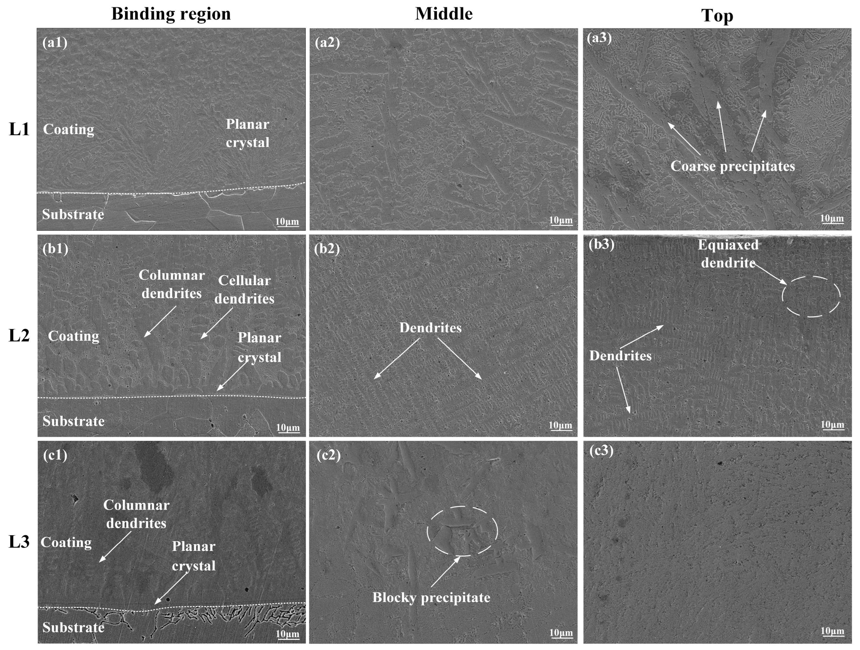
- All three Inconel 718 coatings with different laser powers had a good metallurgical bonding with the 316L stainless steel substrate. The phases were mainly composed of γ~(Fe, Ni) solid solution, Ni3Nb, (Nb0.03Ti0.97) Ni3, and MCX (M = Cr, Nb, Mo). The morphology of the L1–L3 coatings changed from an irregular crystal to a flat crystal along with the increase in laser power. When the laser power was 1600 W, there were some cellular crystals, columnar crystals, dendrites, and compounds.
- (2)
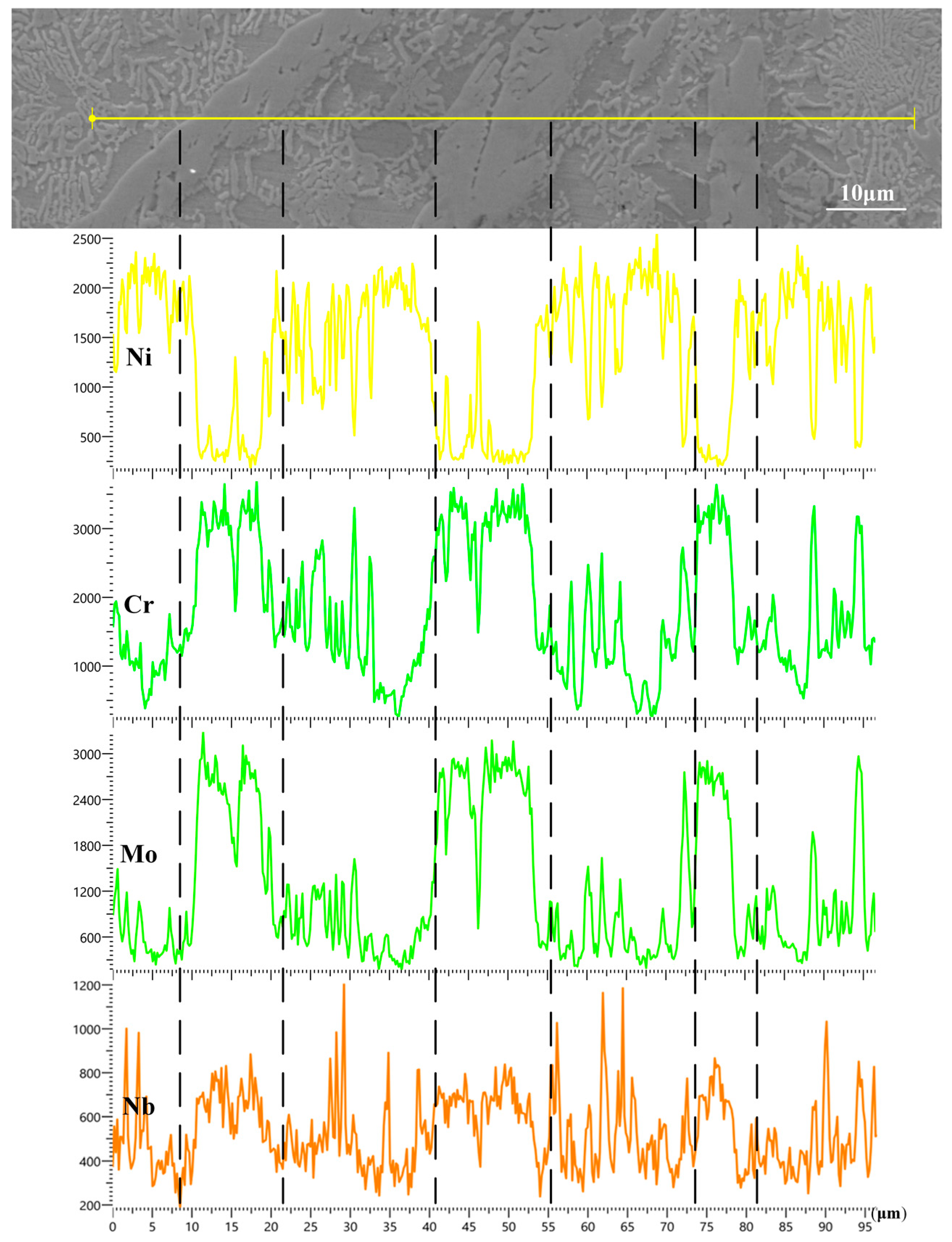
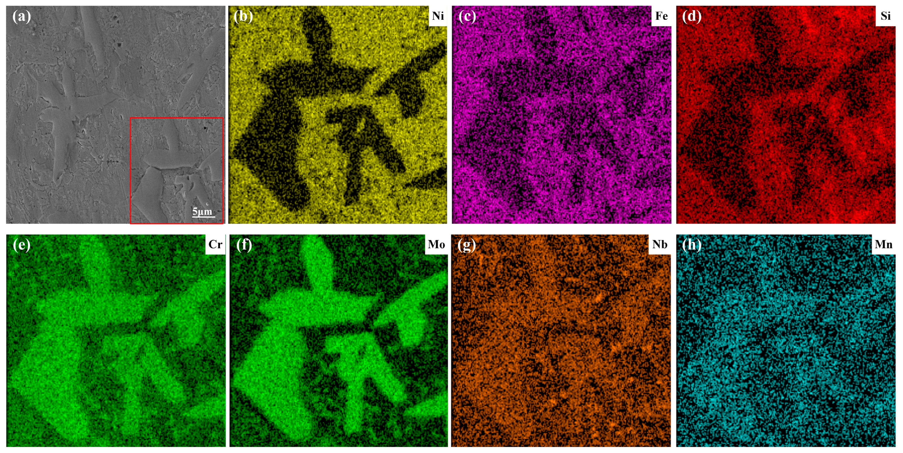
- From the EDS analysis, the background zones in the L1–L3 coatings were mainly the Fe and Ni elements. With the increase in laser power, the content of Fe and Ni had an upward trend, and they formed more γ~(Fe, Ni) solid solution. The irregular blocks in the coating were rich in Cr, Mo, and Nb, which formed the MCX (M = Cr, Nb, Mo) phase. When the laser power was 1600 W, the amount of Cr, Mo, and Nb was larger, indicating that the enrichment degree of Cr, Mo, and Nb was higher in the MCX phases of the L3 coating.
- (3)
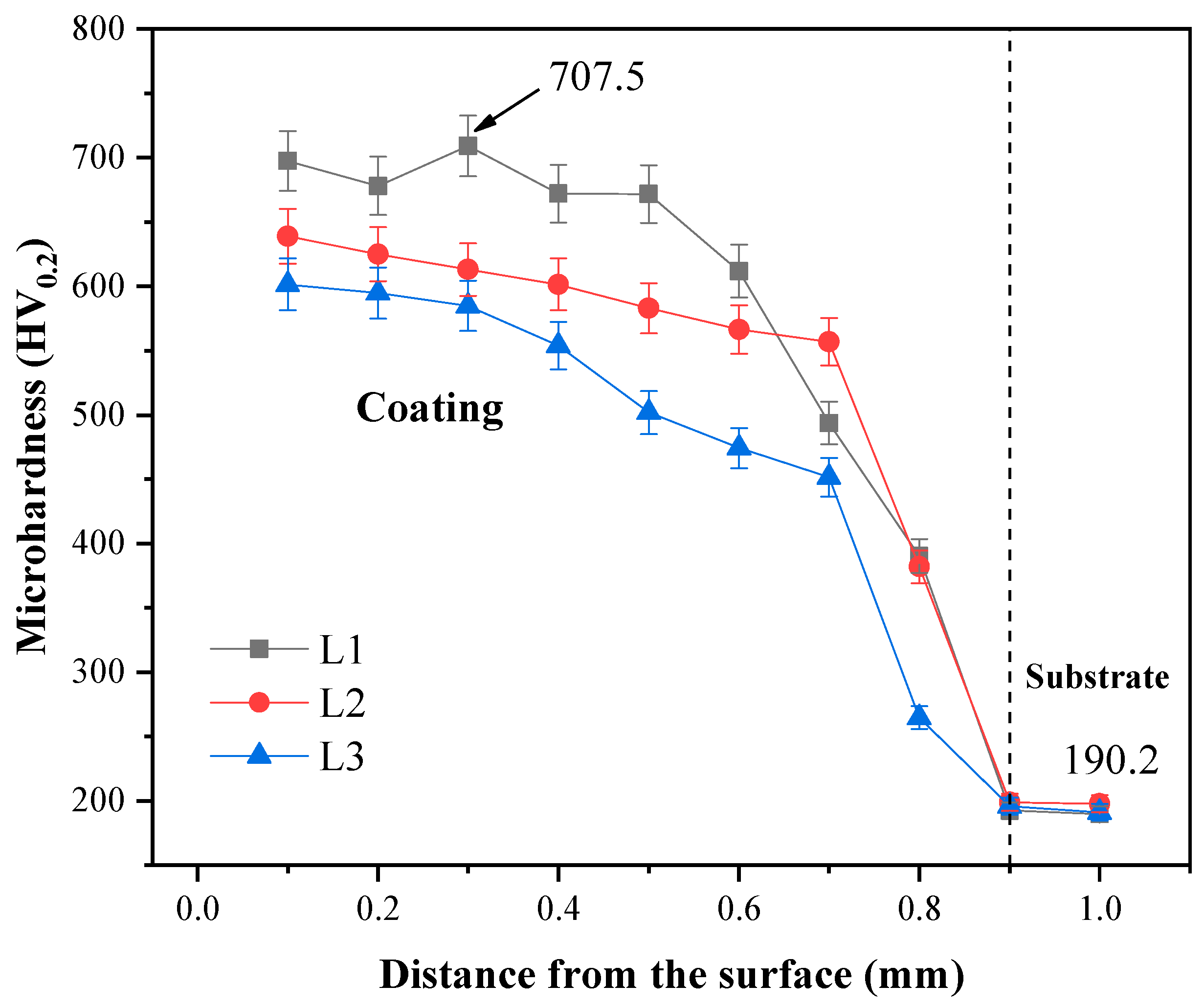
- The average microhardness values of the L1–L3 coatings were 685.6, 604.6, and 551.9 HV0.2, respectively. The L1 coating had the maximum microhardness, which was about 707.5 HV0.2, because the MCX (M = Cr, Nb, Mo)-reinforced phase appeared on the upper part of the L1 coating due to the low laser power. But the microhardness distribution of the L2 coating was more uniform. The crystals of the reinforced phase MCX (M = Cr, Nb, Mo) were tiny and evenly distributed. When the laser power was 1800 W, the molten pool received more energy, and it caused the crystals to grow large.
- (4)
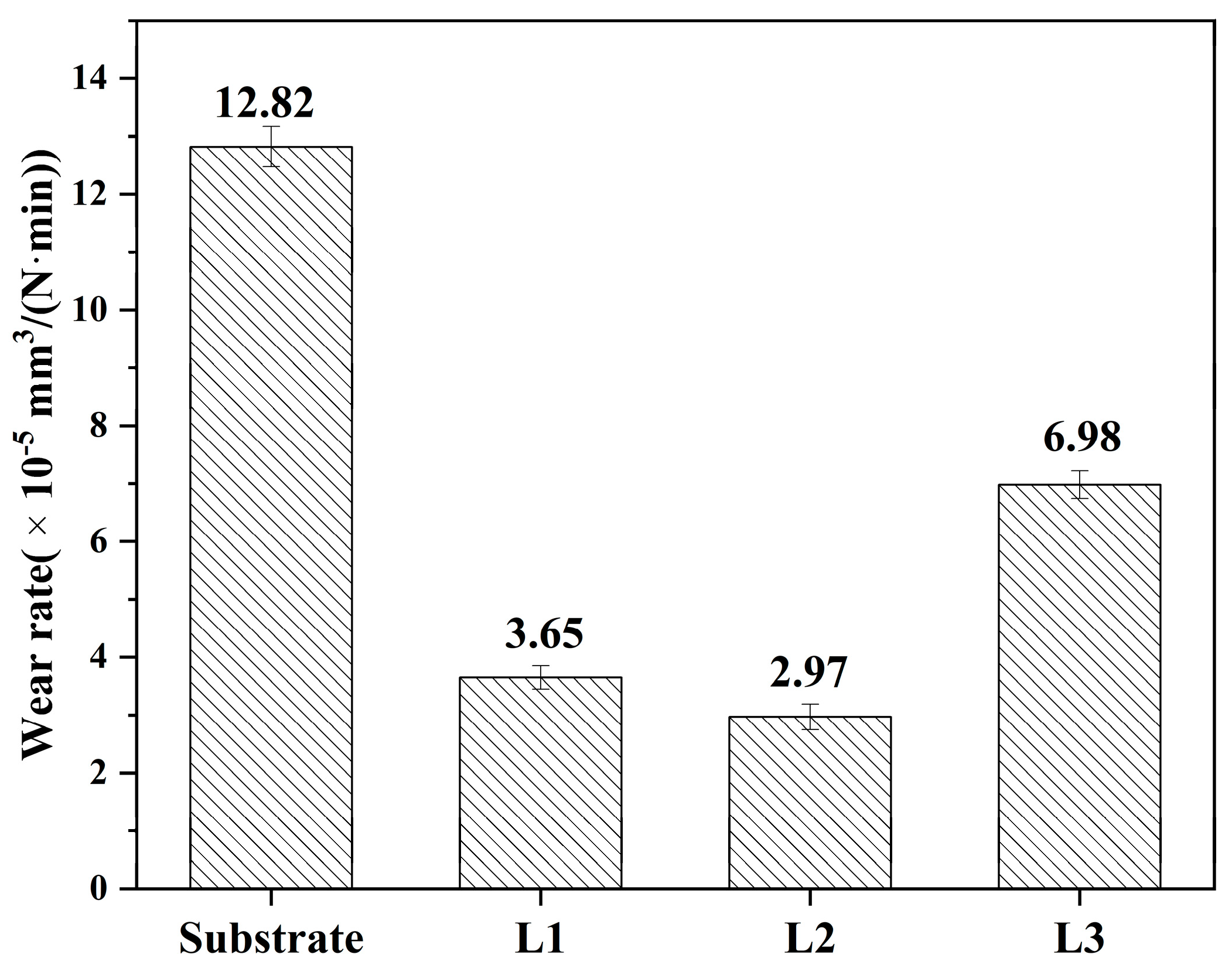
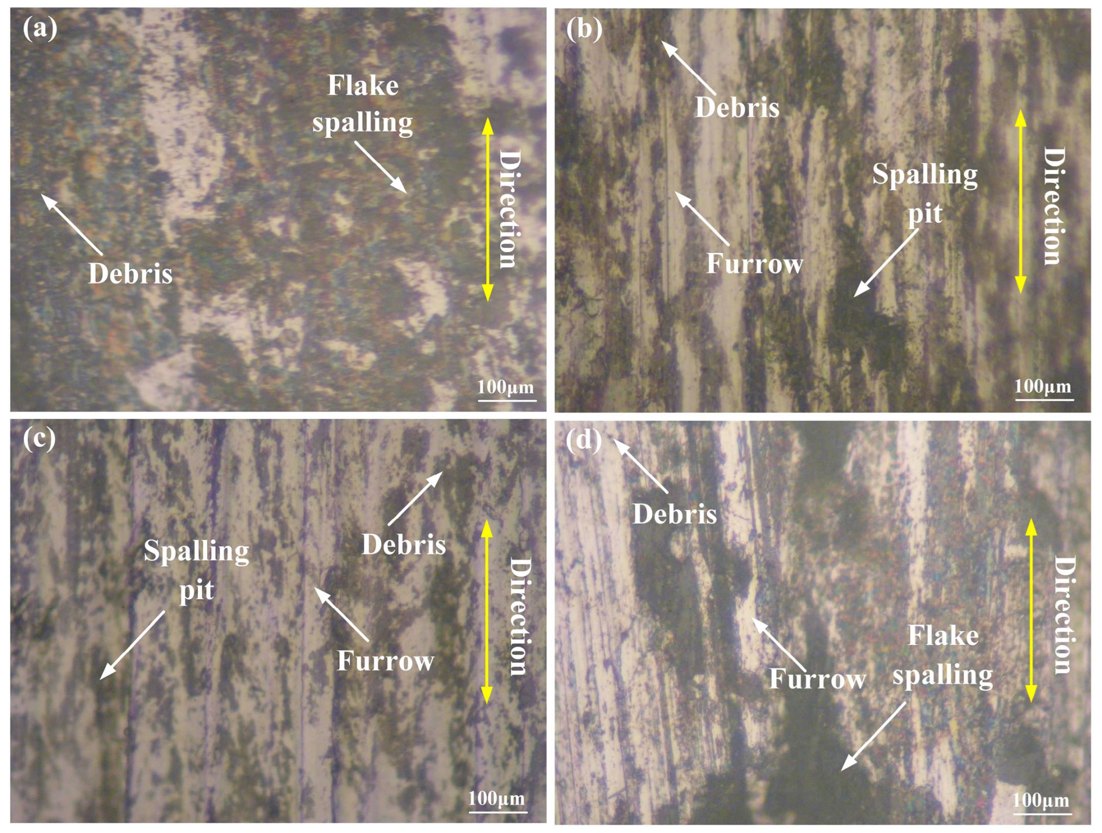
- The main wear mechanism of the 316L substrate was mainly adhesive wear; nevertheless, the main wear mechanism of the L1–L3 cladding coating with different laser powers was mainly adhesive wear and abrasive wear due to the existence of the reinforced phases. The wear rates of the L1–L3 coatings were 3.65 × 10⁻⁵, 2.97 × 10⁻⁵, and 6.98 × 10⁻⁵ mm3·N−1·m−1, respectively. When the laser power was 1600 W, the wear rate of the L2 coating was the lowest due to the fine crystals and compounds.
- (5)
- The proper laser power was found to prepare a good coating with better properties on the surface of 316L stainless steel, which was 1600 W. In future work, research on different scanning speeds and different cladding materials deserves to be investigated further on the surface of 316L stainless steel.
Author Contributions
Funding
Institutional Review Board Statement
Informed Consent Statement
Data Availability Statement
Conflicts of Interest
References
- Ding, H.H.; Yang, T.; Wang, W.J.; Zhu, Y.; Lin, Q.; Guo, J.; Xiao, Q.; Gan, L.; Liu, Q.Y. Optimization and wear behaviors of 316L stainless steel laser cladding on rail material. Wear 2023, 523, 204830. [Google Scholar] [CrossRef]
- Ahmed, N.; Barsoum, I.; Haidemenopoulos, G.; Al-Rub, R.A. Process parameter selection and optimization of laser powder bed fusion for 316L stainless steel: A review. J. Manuf. Process. 2022, 75, 415–434. [Google Scholar] [CrossRef]
- Mohammadreza, D.; Hamid, R.B.R.; Abbas, S.; Mahmood, R.; Ashish, K.K.; Seeram, R.; Pradeep, L.M.; Manoranjan, M.; Ahmad, F.I.; Safian, S. Surface modification of magnesium alloys using thermal and solid-state cold spray processes: Challenges and latest progresses. J. Magnes. Alloys 2022, 10, 2025–2061. [Google Scholar]
- Kumaradhas, P.; Sivapragash, M. Comparison of corrosion behaviour of heat treated, ZrO2 and ZrN PVD coated AZ91D Mg alloy. Mater. Today Proc. 2022, 56, 527–532. [Google Scholar] [CrossRef]
- Diao, Q.W.; Zou, H.B.; Ren, X.Y.; Wang, C.S.; Wang, Y.; Li, H.Y.; Sui, T.Y.; Lin, B.; Yan, S. A focused review on the tribological behavior of C/SiC composites: Present status and future prospects. J. Eur. Ceram. Soc. 2023, 43, 3875–3904. [Google Scholar] [CrossRef]
- Parveez, B.; Kittur, M.I.; Badruddin, I.A.; Kamangar, S.; Hussien, M.; Umarfarooq, M.A. Scientific advancements in composite materials for aircraft applications: A review. Polymers 2022, 14, 5007. [Google Scholar] [CrossRef]
- Liu, Y.; Li, Z.Y.; Li, G.H.; Tang, L. Friction and wear behavior of Ni-based alloy coatings with different amount of WC-TiC ceramic particles. J. Mater. Sci. 2023, 58, 1116–1126. [Google Scholar] [CrossRef]
- Fedor, A.; Igor, M.; Sergey, S.; Fabio, F.; Nikita, M.; Jacobus, M.S.; Vasily, V.Z.; Igor, A.M.; Alexey, K.; Marcelo, A. Laser-induced electron dynamics and surface modification in ruthenium thin films. Vacuum 2023, 212, 112045. [Google Scholar]
- Ayushi, T.; Swaroop, G.; Kandasubramanian, B. Electroless nickel fabrication on surface modified magnesium substrates. Def. Technol. 2019, 15, 636–644. [Google Scholar]
- Eepsita, P.; Saurabh, P.; Kamla, R. Gold-carbon dot (Au@Cd) nanoconjugates based electrochemical sensing of cholesterol and effect of nitrogen ion implantation on sensitivity. Biochem. Biophys. Res. Commun. 2023, 655, 97–103. [Google Scholar]
- Li, C.J.; Luo, X.T.; Yao, S.W.; Li, G.R.; Li, C.X.; Yang, G.J. The bonding formation during thermal spraying of ceramic coatings: A review. J. Therm. Spray Technol. 2022, 31, 780–817. [Google Scholar] [CrossRef]
- Koti, D.; Powell, J.; Naesstroem, H.; Voisey, K.T. Powder catchment efficiency in laser cladding (directed energy deposition). An investigation into standard laser cladding and the ABA cladding technique. J. Laser Appl. 2023, 35, 012025. [Google Scholar] [CrossRef]
- Shi, F.K.; Zhang, Q.K.; Xu, C.; Hu, F.Q.; Yang, L.J.; Zheng, B.Z.; Song, Z.L. In-situ synthesis of NiCoCrMnFe high entropy alloy coating by laser cladding. Opt. Laser Technol. 2022, 151, 108020. [Google Scholar] [CrossRef]
- John, M.; Kuruveri, U.B.; Menezes, P.L. Laser cladding-based surface modification of carbon steel and high-alloy steel for extreme condition applications. Coatings 2022, 12, 1444. [Google Scholar] [CrossRef]
- Li, F.; Zheng, S.; Zhou, F. Study on Mechanical properties of AlFeCrMoNi1.8Nb1.5 eutectic high-entropy alloy coating prepared by wide-band laser cladding. Coatings 2023, 13, 1077. [Google Scholar] [CrossRef]
- Li, M.; Li, C.; Li, B.; Zhou, Y.; Huang, L.; Cai, A.; Cui, C.; Gao, S.; Zhang, G.; Yang, B. Comparison of Fe30Co20Cr20Ni20Mo3.5 high entropy alloy coatings prepared using plasma cladding, high-speed laser cladding, and deep laser cladding. Coatings 2023, 13, 1819. [Google Scholar] [CrossRef]
- Chen, C.; Wang, J.; Ge, Y.; Zhuang, M.; Ma, Z. Microstructure and wear resistance of high-chromium cast iron with multicomponent carbide coating via laser cladding. Coatings 2023, 13, 1474. [Google Scholar] [CrossRef]
- Mohazzab, B.F.; Jaleh, B.; Fattah-alhosseini, A.; Mahmoudi, F.; Momeni, A. Laser surface treatment of pure titanium: Microstructural analysis, wear properties, and corrosion behavior of titanium carbide coatings in Hank′s physiological solution. Surf. Interfaces 2020, 20, 100597. [Google Scholar] [CrossRef]
- Zimogliadova, T.A.; Bataev, A.A.; Lazurenko, D.V.; Bataev, I.A.; Bataev, V.A.; Golkovskii, M.G.; Saage, H.; Ogneva, T.S.; Ruktuev, A.A. Structural characterization of layers fabricated by non-vacuum electron beam cladding of Ni-Cr-Si-B self-fluxing alloy with additions of niobium and boron. Mater. Today Commun. 2022, 33, 104363. [Google Scholar] [CrossRef]
- Jie, M.; Gao, Y.L. Study on hardness and wear resistance of laser cladding Al-Si coating. Appl. Laser 2015, 35, 629–633. [Google Scholar]
- Shi, X.; Wen, D.; Wang, S.; Wang, G.; Zhang, M.; Li, J.; Xue, C. Investigation on friction and wear performance of laser cladding Ni-based alloy coating on brake disc. Optik 2021, 242, 167227. [Google Scholar] [CrossRef]
- Wang, Q.; Zhai, L.L.; Zhang, L.; Zhang, J.W.; Ban, C.Y. Effect of steady magnetic field on microstructure and properties of laser cladding Ni-based alloy coating. J. Mater. Res. Technol. 2022, 17, 2145–2157. [Google Scholar] [CrossRef]
- Gao, Z.; Ren, H.; Geng, H.; Yu, Y.; Gao, Z.; Zhang, C. Effect of CeO2 on microstructure and wear property of laser cladding Ni-Based coatings fabricated on 35CrMoV Steel. J. Mater. Eng. Perform. 2022, 31, 9534–9543. [Google Scholar] [CrossRef]
- Figueredo, E.W.A.; Apolinario, L.H.R.; Santos, M.V.; Silva, A.C.S.; Avila, J.A.; Lima, M.S.F.; Santos, T.F.A. Influence of laser beam power and scanning speed on the macrostructural characteristics of AISI 316L and AISI 431 stainless steel depositions produced by laser cladding process. J. Mater. Eng. Perform. 2021, 30, 3298–3312. [Google Scholar] [CrossRef]
- Nie, M.H.; Zhang, S.; Wang, Z.Y.; Zhang, C.H.; Chen, H.T.; Chen, J. Effect of laser power on microstructure and interfacial bonding strength of laser cladding 17-4PH stainless steel coatings. Mater. Chem. Phys. 2022, 275, 125236. [Google Scholar] [CrossRef]
- Zhang, H.; Pan, Y.J.; Zhang, Y.; Lian, G.F.; Cao, Q. Influence of laser power on the microstructure and properties of in-situ NbC/WCoB–TiC coating by laser cladding. Mater. Chem. Phys. 2022, 290, 126636. [Google Scholar] [CrossRef]
- Hu, Z.; Li, W.; Zhao, Y. The effect of laser power on the properties of M3B2-type boride-based cermet coatings prepared by laser cladding synthesis. Materials 2020, 13, 1867. [Google Scholar] [CrossRef]
- Shayanfar, P.; Daneshmanesh, H.; Janghorban, K. Parameters optimization for laser cladding of inconel 625 on ASTM A592 steel. J. Mater. Res. Technol. 2020, 9, 8258–8265. [Google Scholar] [CrossRef]
- Huang, Y.; Hu, Y.; Zhang, M.; Mao, C.; Wang, K.; Tong, Y.; Li, K. Multi-objective optimization of process parameters in laser cladding CoCrCuFeNi high-entropy alloy coating. J. Therm. Spray Technol. 2022, 31, 1985–2000. [Google Scholar] [CrossRef]
- Li, Z.Y. Research on laser cladding layer on the surface of the stainless steel and its properties. Dissertation 2023, 17, 130005. [Google Scholar]


| Component | Fe | C | Mn | Ni | Si | Mo | Cr |
|---|---|---|---|---|---|---|---|
| Mass fraction | Bal | ≤0.08 | ≤2.0 | 10.0–14.0 | ≤1.00 | 2.0–3.0 | 16.0–18.5 |
| Component | Ni | Si | Mo | Cr | Co | Ti | Nb | Fe |
|---|---|---|---|---|---|---|---|---|
| Mass fraction | Bal | 0.4 | 2.8–3.3 | 17.0–21.0 | 1.0 | 0.7–1.2 | 4.8–5.5 | 14.2 |
| NO. | Laser Power (W) | Scanning Speed (mm/s) | Spot Diameter (mm) | Overlap Rate |
|---|---|---|---|---|
| L1 | 1400 | 2 | 3 | 30% |
| L2 | 1600 | 2 | 3 | 30% |
| L3 | 1800 | 2 | 3 | 30% |
| Element | P1 | P2 | P3 | P4 | P5 | P6 |
|---|---|---|---|---|---|---|
| Ni | 38.29 | 40.31 | 33.87 | 42.48 | 29.11 | 44.42 |
| Fe | 31.58 | 37.41 | 37.18 | 39.84 | 38.05 | 41.31 |
| Cr | 16.72 | 14.69 | 21.48 | 13.62 | 25.22 | 10.06 |
| Mo | 6.53 | 0.65 | 3.52 | 1.31 | 4.34 | 1.24 |
| Nb | 1.60 | 0.09 | 1.08 | 0.25 | 0.87 | 0.17 |
| Si | 4.64 | 6.30 | 2.19 | 2.04 | 1.83 | 2.23 |
| Mn | 0.53 | 0.55 | 0.67 | 0.46 | 0.58 | 1.04 |
Disclaimer/Publisher’s Note: The statements, opinions and data contained in all publications are solely those of the individual author(s) and contributor(s) and not of MDPI and/or the editor(s). MDPI and/or the editor(s) disclaim responsibility for any injury to people or property resulting from any ideas, methods, instructions or products referred to in the content. |
© 2023 by the authors. Licensee MDPI, Basel, Switzerland. This article is an open access article distributed under the terms and conditions of the Creative Commons Attribution (CC BY) license (https://creativecommons.org/licenses/by/4.0/).
Share and Cite
Liu, Y.; Zhu, L.; Li, Z.; Yu, M.; Gao, Y.; Liang, H. Microstructure and Properties of Inconel 718 Coatings with Different Laser Powers on the Surface of 316L Stainless Steel Substrate. Coatings 2023, 13, 1947. https://doi.org/10.3390/coatings13111947
Liu Y, Zhu L, Li Z, Yu M, Gao Y, Liang H. Microstructure and Properties of Inconel 718 Coatings with Different Laser Powers on the Surface of 316L Stainless Steel Substrate. Coatings. 2023; 13(11):1947. https://doi.org/10.3390/coatings13111947
Chicago/Turabian StyleLiu, Yu, Lin Zhu, Zeyu Li, Miao Yu, Yali Gao, and Hui Liang. 2023. "Microstructure and Properties of Inconel 718 Coatings with Different Laser Powers on the Surface of 316L Stainless Steel Substrate" Coatings 13, no. 11: 1947. https://doi.org/10.3390/coatings13111947