Article

Research on Bending Performance of Concrete Sandwich Laminated Floor Slabs with Integrated Thermal and Sound Insulation

1
School of Civil Engineering, Central South University, 22 Shaoshan Road, Changsha 410075, China
2
National Engineering Laboratory for High Speed Railway Construction, Central South University, Changsha 410075, China
3
Chenzhou Changxin Residence Technology Co., Ltd., 8 Huihuang Road, Chenzhou 423000, China
4
Hunan Zhongda Design Institue Co., Ltd., 68 Shaoshan Road, Changsha 410075, China
5
Hunan Construction Project Investment Management Co., Ltd., 199 Xiangfu Road, Changsha 410007, China
6
Railway Group 5 Mechanization of Engineering Co., Ltd., 32 HongtangCong Road, Hengyang 421002, China
7
School of Civil Engineering, Central South University of Forestry and Technology, 498 Shaoshan Road, Changsha 410004, China
*
Authors to whom correspondence should be addressed.
Coatings 2022, 12(8), 1075; https://doi.org/10.3390/coatings12081075
Submission received: 29 June 2022 / Revised: 22 July 2022 / Accepted: 28 July 2022 / Published: 30 July 2022
(This article belongs to the Special Issue Current Research in Cement and Building Materials)

Abstract

:
In this study, a full-scale test on the bending performance of concrete sandwich laminated floor slabs with integrated thermal and sound insulation was carried out, and the effects of different reinforcement ratios on the bending performance of concrete sandwich laminated floor slabs were investigated as well as the variation law of the failure modes, characteristic loads, load-mid span deflection, load-rebar strain curves, and anti-slip performance. The results indicate that the concrete sandwich laminated floor slabs present typical bending failure characteristics. According to bending failure characteristics, the damage process can be divided into three stages, i.e., elasticity, cracking, and failure. The bearing capacity significantly increases with the increase in reinforcement ratio. The normal service, yield, and ultimate loads of bearing capacity of the floor slabs with a larger reinforcement ratio increase by 54.55%, 52.94%, and 46.46%, respectively. Moreover, the mid-span deflection decreases significantly with the increase in reinforcement ratio, and the cracking expansion is also delayed. Before cracking, the prefabricated layer and laminated layer can realize load bearing together, and the floor slab is in a state of complete interaction. When the floor slabs reach the ultimate state, the superimposed surface produces a sliding effect, and the floor slab is in a state of partial interaction. The finite element analysis software ABAQUS (with the version number of ABAQUS 2020, the chief creator of David Hibbitt, and the sourced location of the United States) was used to perform nonlinear numerical simulation. The test results accord well with the simulation results, which verifies the correctness of the finite element model. Based on finite element simulation, the influence of post-cast concrete strength on the ultimate load can be ignored.

1. Introduction

Laminated structures are widely used in architecture, aviation, train locomotives, and other fields. At present, extensive experimental research and theoretical analysis have been carried out [1,2,3,4]. Floor is an important inner envelope of the building to ensure safety, stability, and durability, which should be both heat insulation, sound insulation, waterproof, and moisture-proof at the same time. Laminated floor slab is a prefabricated concrete floor structure composed of prefabricated and laminated layers. It has good integrity and seismic resistance and has become an important horizontal bearing member of the prefabricated concrete structure [5,6]. However, its thermal and sound insulation effects fail to meet the code’s requirements [7]. Therefore, it is necessary to study the structural system of thermal and acoustic bearing integrated floor slab that integrates energy saving, environmental protection, and green low-carbon [8,9]. The concrete sandwich laminated floor slab has the advantages of light weight, high strength, sound insulation, energy saving, fire resistance, good seismic performance, and convenient installation [10]. It is easy to realize product industrialization, standardization, and construction mechanization. Furthermore, it has become one of the most rapidly developing laminated floor structures.
Many studies regarding mechanical property tests and theoretical analysis of concrete sandwich laminated floor slabs have been conducted worldwide [11,12,13,14]. For example, Li et al. [15] derived a deflection calculation formula for the concrete sandwich plate in the ultimate limit state by experimental verification and numerical simulation technology. Chen et al. [16] investigated the factors that affect the bending performance of double reinforced concrete sandwich panels. Luo et al. [17] conducted bending tests of laminated slabs, and the results indicated that the prefabricated bottom plate construction form and core material significantly affect the bending performance of sandwich laminated floor slabs. Joseph et al. [18,19] analyzed the bending properties of prefabricated concrete sandwich panels under punching and bending loading conditions. Ahmad et al. [20] indicated that the cracks on the plate side were characterized by the combined effect of bending and shear stresses due to the sandwich layer. Tomlinson et al. [21] studied bending tests of laminated floor slabs with EPS as the core layer, and the results indicated that the floor slabs worked partially compositely when the shear connector failed. Currently, the expanded polystyrene (EPS) plate is mostly used as the core of concrete sandwich laminated floor slabs, which has advantages of light weight, low water absorption, good thermal insulation performance, etc. [22]. However, it has poor fire performance and is easy to burn, which can produce toxic smoke and has great safety hazards. Due to the less attention to the fire performance of insulation materials, fire accidents have been common in recent years [23]. Phenolic foam has low thermal conductivity, high fire safety coefficient, good thermal and sound insulation, etc. Therefore, when used in concrete sandwich laminated floor slabs, the thermal and sound insulation performance and the safety of the slab can be significantly improved.
The effective connection between the prefabricated and laminated layers is the basis that ensures the joint work of the laminated structure. According to research status worldwide, the primary method to solve this problem is the steel bar trusses in the laminated slabs. Wang et al. [24] investigated the bending performance of laminated slabs with trusses and stirrup reinforcement as the connections, respectively, and the results indicated that both structural forms could significantly improve the stiffness and shear resistance. Refs. [25,26,27] presented that truss webs can ensure the shear resistance of the laminated face. Huang et al. [28,29] investigated the bending performance of laminated slabs with different prefabricated bottom plates, and a design recommendation for structural measures was proposed. Thanoon et al. [30] regarded that truss reinforcement can provide good integrity to the laminated slab in all bending phases. Steel bar trusses can improve the shear capacity, limit the inter-story slip, and enhance the co-working property of the laminated floor slabs [31]. However, there are disadvantages such as numerous trusses, dense truss spacing, high cost, and complex vibration and compaction of post-cast layer concrete. Given the shortcomings of the steel bar truss connectors, the stirrup rebar is proposed to replace the steel bar trusses. Moreover, due to the advantages of low energy consumption, low cost, and saving the amount of steel reinforcement, the CRB600H high-strength steel bars are employed, which has remarkable economic and social benefits [32].
This paper proposed thermal and sound insulation integrated concrete sandwich laminated floor slab (Abbr. sandwich laminated floor slab). The sandwich laminated floor slab was combined with concrete layers on both sides and a phenolic core layer connected through the steel reinforcement grid. The phenolic foam board was the insulation layer, and the reinforcement grid consisted of stirrup rebars and upper and lower rebar mesh. The two-point bending tests of sandwich laminated floor slabs with different reinforcement ratios were carried out. The damage pattern, reinforcement strain, crack development distribution characteristics, and bending bearing capacity process were discussed. The influence law of reinforcement ratio on the characteristic load was also analyzed. Moreover, the slip resistance of sandwich laminated floor slabs in different stages was also studied. The force performance was numerically simulated by finite element analysis software ABAQUS. The results provided a scientific basis for the design and application of concrete sandwich laminated floor slabs with integrated thermal and sound insulation in practical projects.

2. Experimental Study

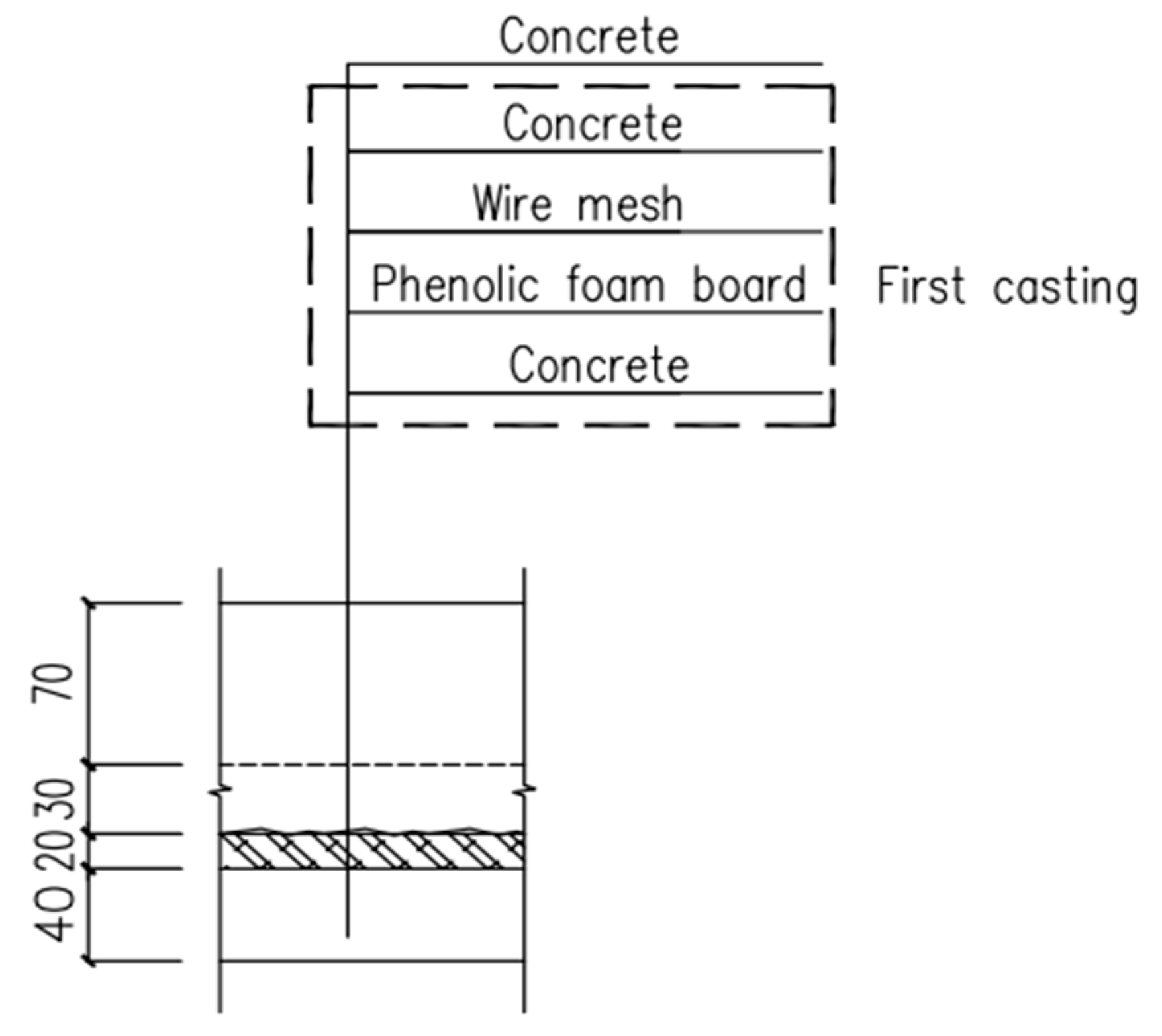
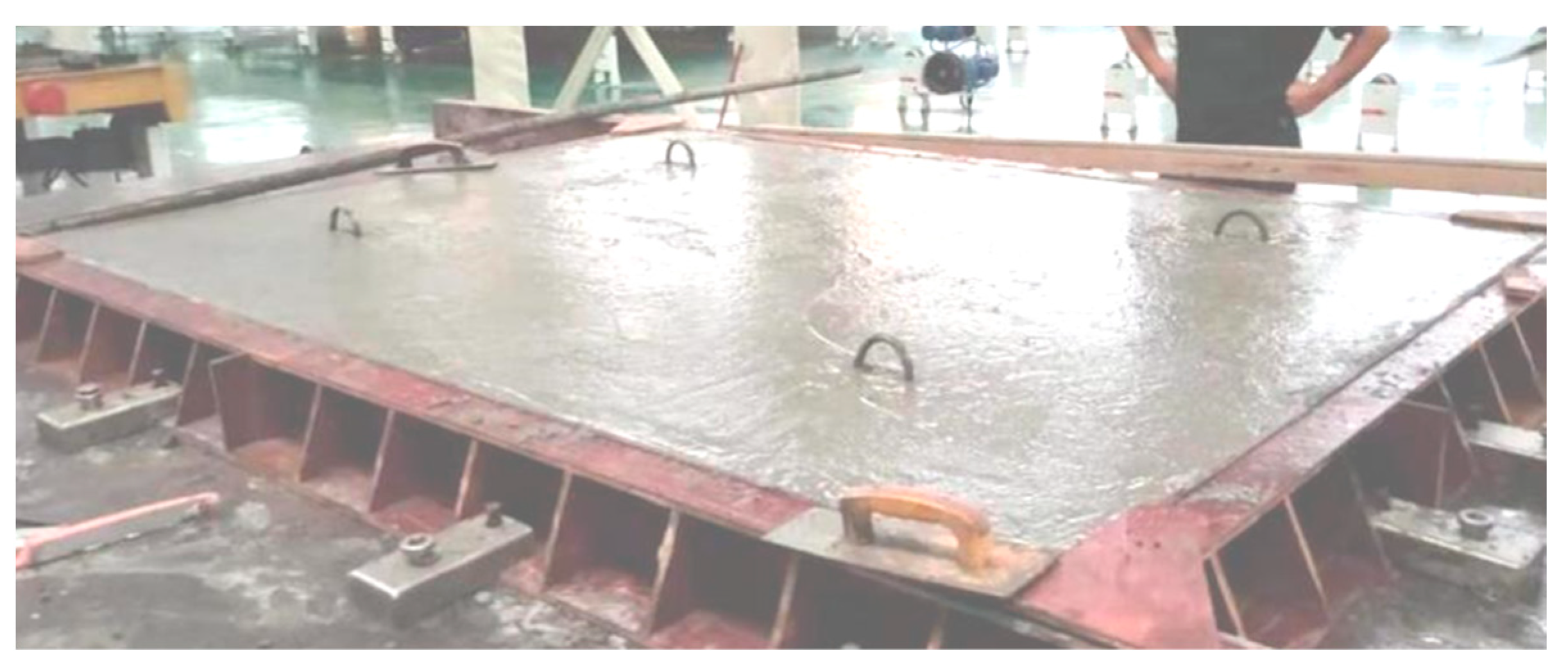
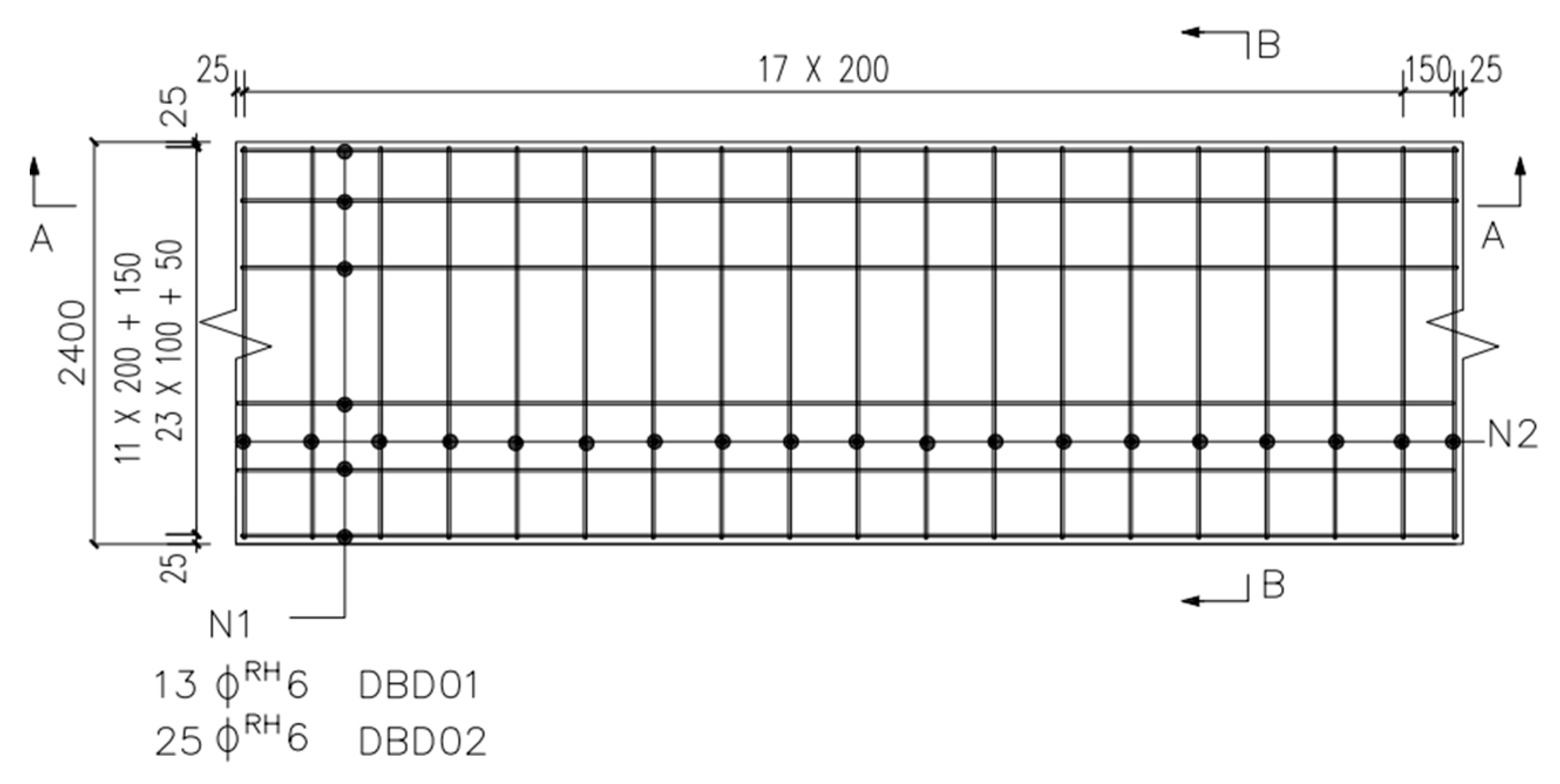
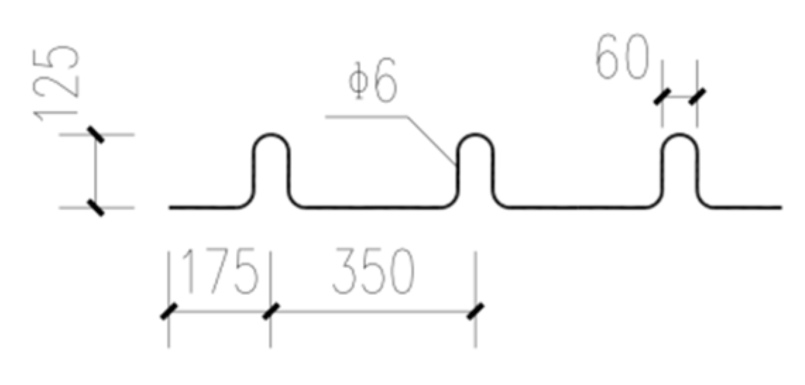
2.1. Design and Fabrication of Specimen
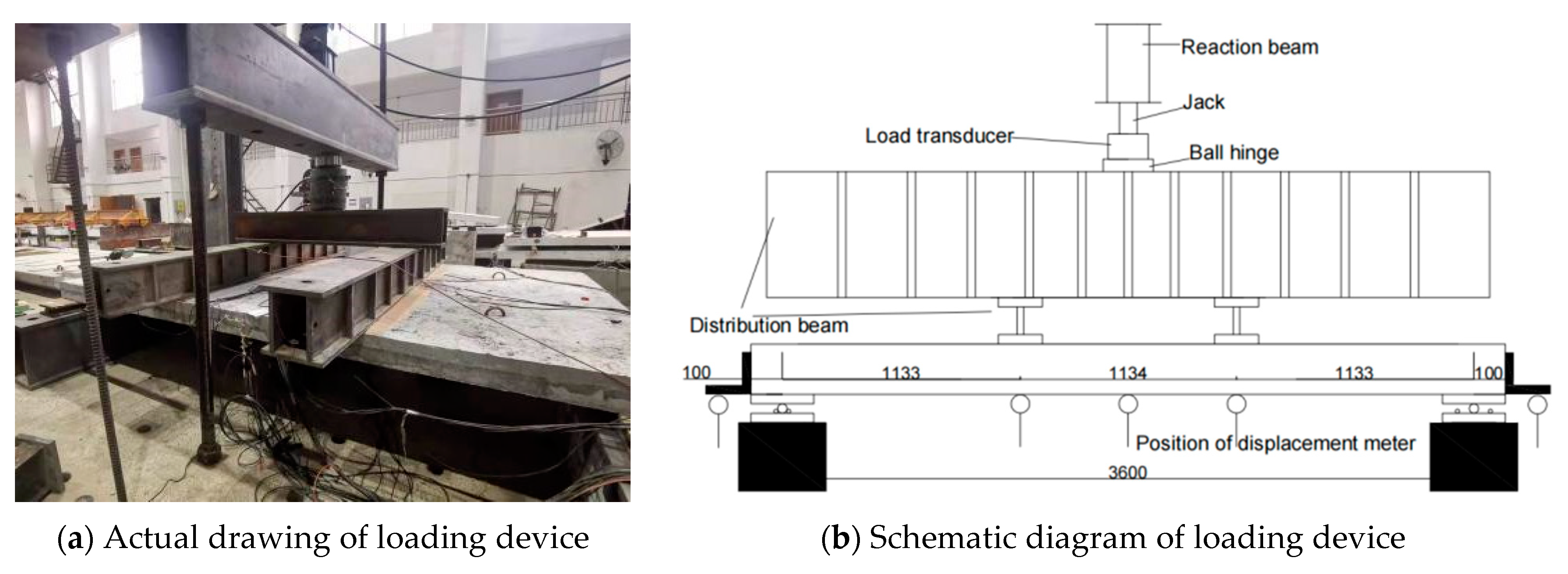
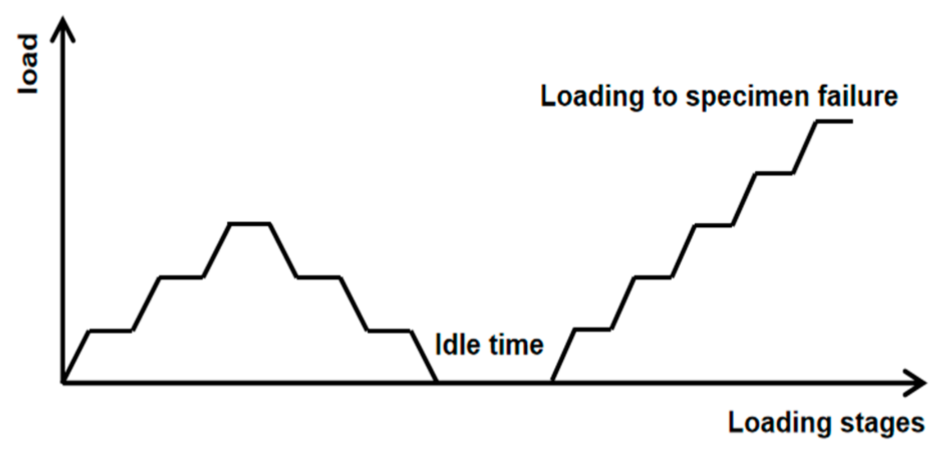
Two full-scale specimens were subjected to bending loads with the number of DBD01 and DBD02. Both the specimens were of the same size of 3600 mm × 2400 mm, and the thickness of the prefabricated and laminated layers was 90 mm and 70 mm, respectively. Figure 1 shows the schematic diagram of the interlayer structure.
Table 1 lists the principal design parameters of the specimens, Figure 2 shows the pouring process, and Figure 3, Figure 4 and Figure 5 present the reinforcement diagram and the constructional detail.
The strength grade of concrete in the prefabricated and laminated layers of the specimen is C40. The type and diameter of reinforcement are the same, but their reinforcement ratios are different. The stirrup rebar is HPB300 with the design value of tensile strength fy = 300 MPa. The longitudinal bearing and transverse distribution bars are CRB600H, with the design value of tensile strength fy = 540 MPa. The diameters of longitudinal and distribution reinforcement are 8 mm and 6 mm, respectively. The surface reinforcement is HRB400 with a diameter of d = 8 mm, and the design value of tensile strength fy = 400 MPa. Table 2 shows the mechanical property parameters of the steel bars.
The specimens were fabricated and cured according to GB/T50081-2019 [33] and were placed into a pool with the saturated solution of calcium hydroxide at (20 ± 2) °C for 28 d after demolding. There were two groups of pressure test blocks with the same batch of materials for the prefabricated and laminated layers. Moreover, three parallel specimens of each group were used to reduce the error caused by the randomness of the specimen. The loading equipment is a 100-ton electro-hydraulic servo material machine designed and produced by Shanghai New Sansi Measuring Manufacturing Co., Ltd. (Shanghai, China). Figure 6 shows the loading device and the failure mode under compression. Table 3 presents the mechanical performance parameters.

2.2. Test Methods

According to GB 50010-2010 [34], instead of the equalized load, two-point centralized loading was used to load with the loading point at the trisection of the span. Sand was pre-laid at the loading point for leveling to prevent stress concentration. Figure 7 shows the schematic diagram of the test device and loading.
The load-controlled loading system was used, including preloading and subsequent formal loading processes. The preloading process consisted of three levels, each taking 20% of the cracking load, then unloading after the preloading process and entering the formal loading stage. The formal loading process was divided into four stages. In the first stage, 20% of the cracking load was taken for each level and then entered the second stage after reaching 80% of the cracking load, and 5% of the cracking load value should be taken for each stage. Observing the strain change of the concrete at the bottom of the slab, the measured cracking load was determined when the strain deviated from the linear change significantly, and cracks appeared at the bottom of the slab. After the floor slab cracking, it entered the third stage, and 10% of the calculated value of the cracking load was taken for each level until the bearing capacity. Finally, it entered the fourth stage when reaching the ultimate state, and 5% of the limit load value was taken for each level until the specimen failed. The load holding time of each stage was 10 min. Figure 8 shows the loading system.

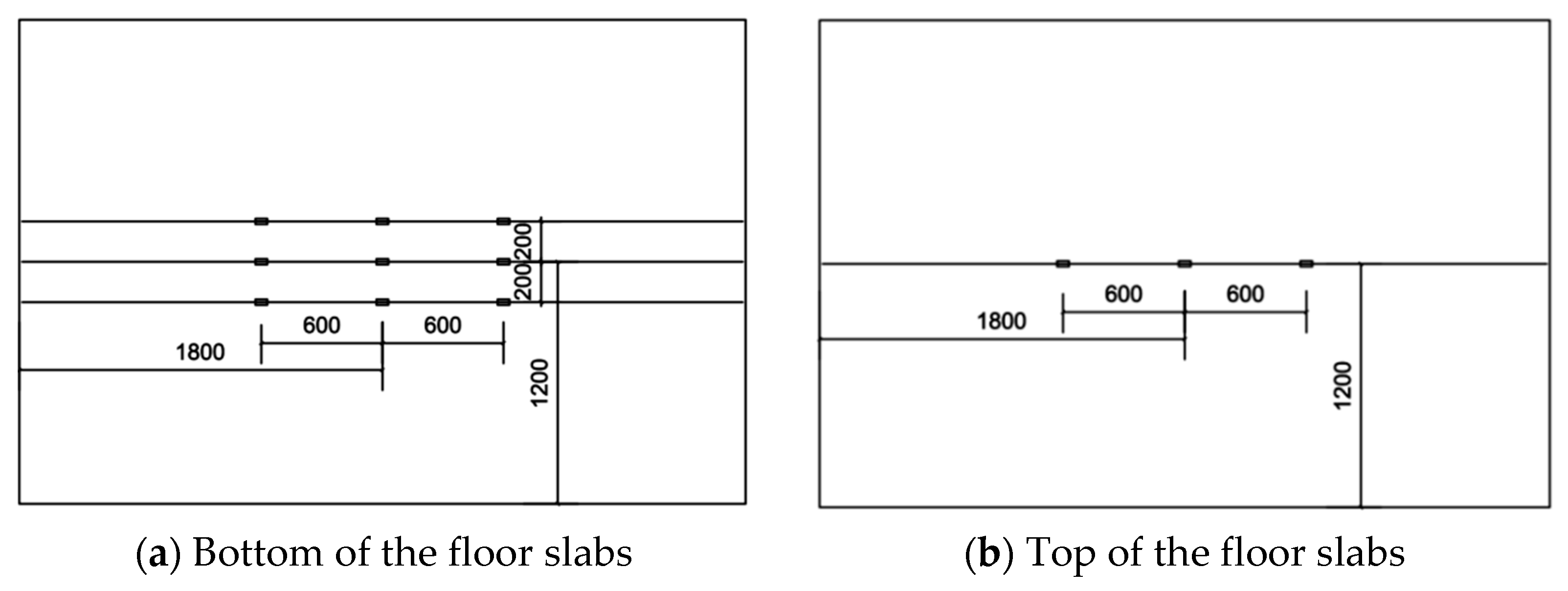
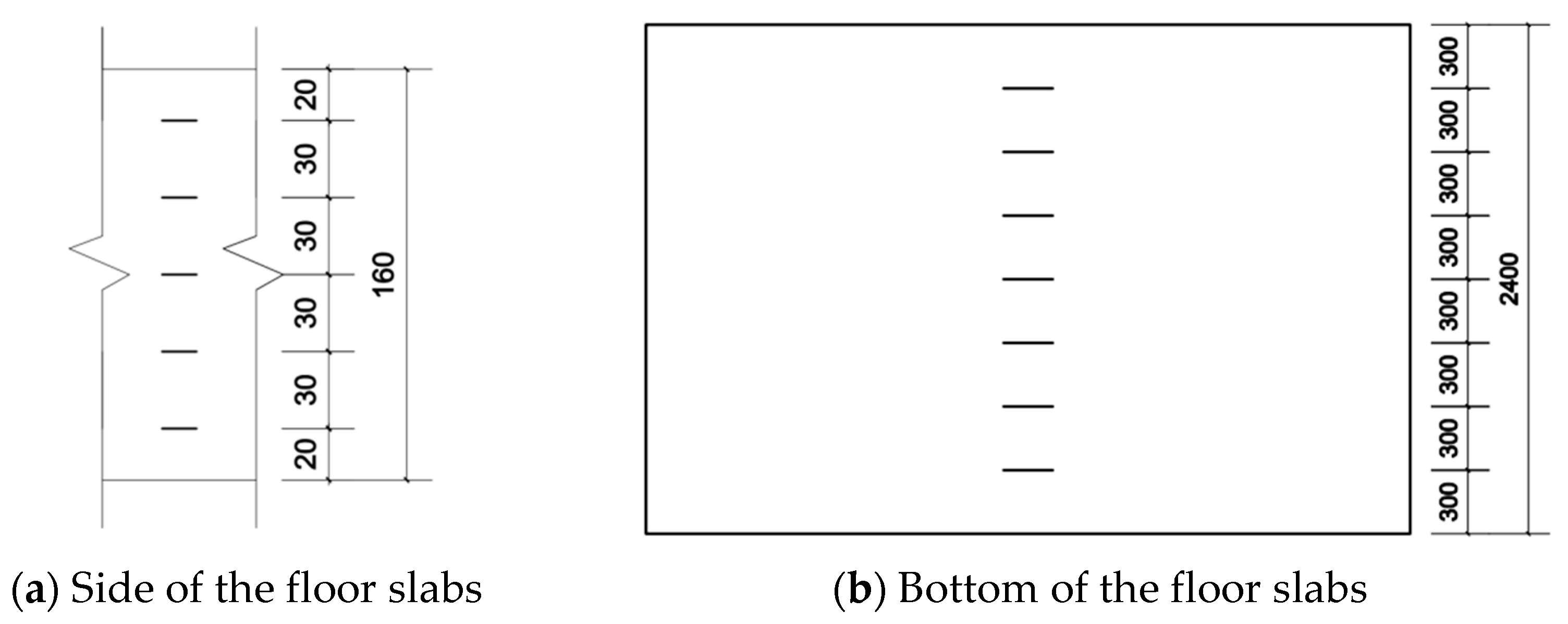
2.3. Measuring Point Layout

The reinforced strain gauges were arranged in the 1/2 and 1/3 of the bottom span and the middle of the top span, as shown in Figure 9. Concrete strain gauges were placed in the middle of both span bottom and side, as shown in Figure 10. The displacement gauges were placed at the 1/2 and 1/3 of the span and two-end supports to measure the corresponding deflection.

3. Results and Discussions

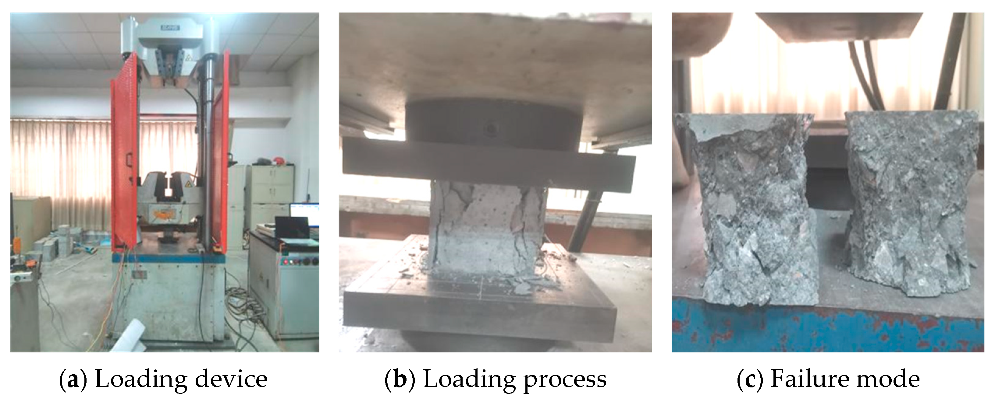
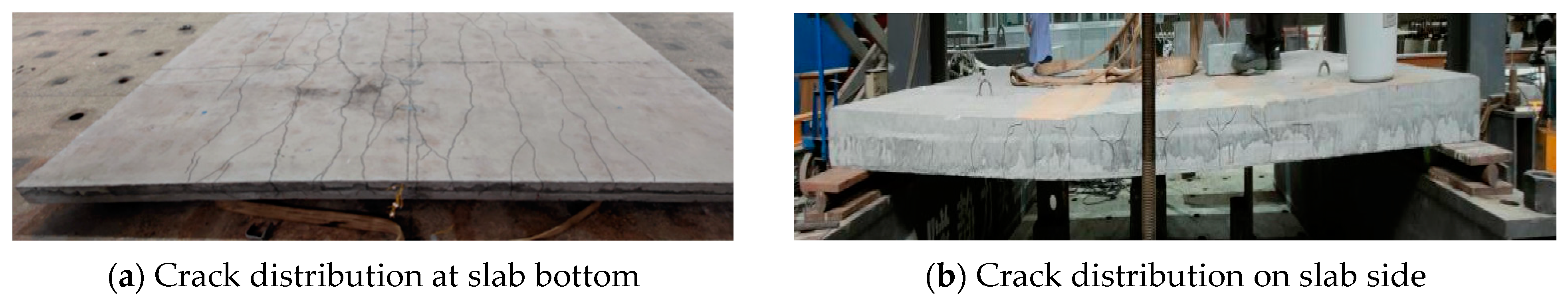
3.1. Failure Characteristics

The mid-span deflection, steel bar, and concrete strain increase slightly when the load is small. The first crack appears in the mid-span pure bending section with a load of 13 kN. At this time, the strain of steel bar, concrete, and the mid-span deflection increases slightly. Moreover, the cracks develop from the middle to both ends along the width with the load increases and mainly distributed symmetrically in the mid-span.
Firstly, the cracks on the side of the slab extend vertically upward in mid-span, and then the bending shear diagonal cracks successively appear within 1/3 of the span as the load increases. The interface between vertical and inclined cracks is a superposition surface, and the inclination angle of cracks decreases gradually. When the load is 66 kN, the deflection reaches 17.20 mm, corresponding to the width of 0.26 mm. According to GB 50010-2010, the deflection and crack width limit in the normal use stage is L0/200 = 17 mm and 0.2 mm, respectively [34]. Based on the deflection and crack width control, the specimen reaches the normal use stage. When the load is 186 kN, the mid-span deflection instantly increases to 68.2 mm. According to GB 50010-2010, the deflection limit in the ultimate stage is L0/50 = 68 mm [34], and the specimen reaches the ultimate state of the bearing capacity. The cracks at the bottom are mainly vertical to the axis of the short span and densely distributed within 1/3 of the span, as shown in Figure 11.
The first crack appears in the mid-span pure bending section when the load reaches 39 kN and then enters the limit stage of normal usage with the deflection of 17.10 mm when the load is 102 kN. The horizontal cracks appear at the superimposed surface when the load is 199 kN. According to GB50010-2010, the ultimate state of the bearing capacity is reached with a deflection of 17.20 mm and a width of more than 1.5 mm. Figure 12 shows the failure mode and crack distribution.
The cracking load is significantly higher, and the crack number and growth rate of DBD02 are apparently lower than that of DBD01, which indicates that the mid-span deflection of the specimen is reduced and the cracking expansion is delayed with the increase in reinforcement ratio. Table 4 shows the characteristic load of the sandwich laminated floor slab. Pcr is the cracking load, P1/200 is the normal use load, Py is the yield load, and Pu is the ultimate load. Both sandwich laminated floor slabs present typical bending failure characteristics with similar early failure characteristics and good ductility. The cracking load of DBD02 is three times of DBD01, and the normal use load, yield load, and ultimate load of bearing capacity increase by 54.55%, 52.94%, and 46.46%, respectively. This indicates that the ultimate bearing capacity is significantly improved with the increase in the reinforcement ratio, but the bonding performance of the superimposed surface should be considered as well.

3.2. Bending Performance Analysis

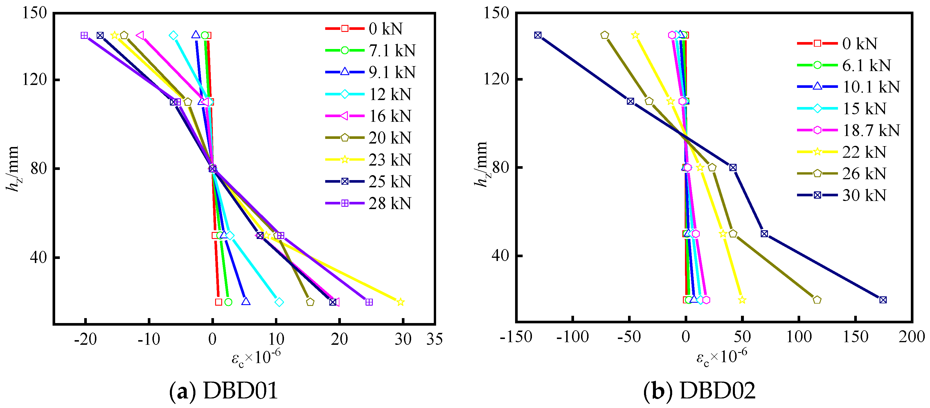
3.2.1. Verification of Plane-Section Assumption

Figure 13 shows the average strain distribution of concrete along the section height in the mid-span, where εc is the concrete strain and h is the section height. Since the strain gauges are damaged after cracking, only the strain data without the cracking of floor slab side are plotted. As seen in Figure 13, the concrete average strain distribution along the height of the mid-span section is linear, which conforms to the assumption of the flat section. Strain hysteresis is not apparent between the prefabricated and laminated layers, so the flat section assumption can be taken as the basic assumption in the bearing capacity calculation analysis.

3.2.2. Load-Mid Span Deflection Relationship

As shown in Figure 14, the load-mid span deflection curve is characterized by three straight lines, i.e., elasticity, cracking, and failure, indicating that the specimen has good ductility.
a. Elastic stage (0~s). Before cracking, the specimen is in the elastic stage, and the load is proportional to the mid-span deflection. Due to the low tensile strength and high stiffness of concrete, the curve is short and steep. The cracking load of DBD02 is three times of DBD01 because the reinforcement ratio of DBD02 is twice of DBD01. The increase in reinforcement ratio can effectively delay the crack propagation.
b. Cracking stage (s~u). The slope of the curve and the bending stiffness decrease significantly after the crack appears. The load-mid span deflection curve nonlinearly increases as the floor slab enters the plastic stage. The cracking load, normal use load, and yield load of both specimens are 10%~20%, 50%~55%, and 80%~85% of the ultimate load, respectively. The curve slope of DBD02 is significantly larger than that of DBD01, and the deflection of DBD01 is lower than that of DBD01, which indicates that the increase in reinforcement ratio can effectively improve the late rigidity and reduce the mid-span deflection greatly.
c. Failure stage (u~). The curve slope sharply decreases, the load almost remains unchanged, and the deformation rapidly develops due to the low tensile strength of the phenolic foam board after the steel bars yield, which indicates that the sandwich layer significantly influences the latal rigidity and bearing capacity of specimens. The ultimate state of bearing capacity reaches when the concrete is crushed or deformed excessively, and the load-mid span deflection curve is almost horizontal.

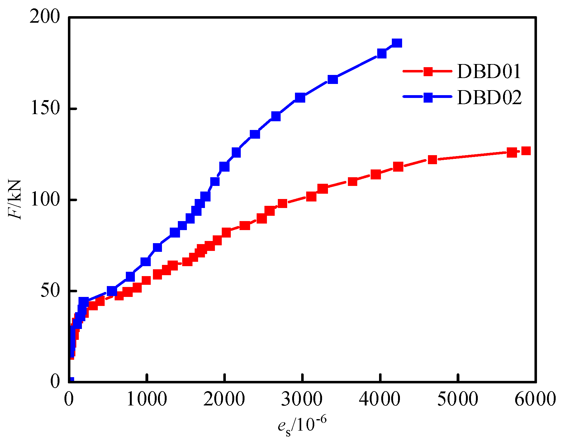
3.3. Load-Reinforcement Strain Relationship

As shown in Figure 15, both sandwich laminated floor slabs have the same variation law. The curve development presents three-stage characteristics, i.e., elastic, elastoplastic, and failure. The curve develops linearly with a large curve slope when the load is small. When it reaches the cracking load, the reinforcement strain suddenly increases, and the slope of the curve decreases obviously. The variation trend is consistent with the load-mid span deflection curve. At this time, the concrete in the tensile zone fails, and the steel stress and strain instantly increase. The curve develops nonlinearly with the load increases, which indicates that the steel bar enters the plastic stage. Furthermore, the mid-span strain difference between the specimens increases with the increase in load, which demonstrates that the reinforcement stress is effectively retarded with the increase in reinforcement ratio.

4. Analysis of the Slip Resistance of Sandwich Laminated Floor Slabs

4.1. Premise of Analysis

The concrete sandwich laminated floor slab is composed of reinforcement, concrete, and phenolic foam board with completely different physical and mechanical properties, which results in complex mechanical properties of the floor slab under load. The bonding performance of the laminated surface is the key to maintaining the integrity of the laminated floor slab, and the bending capacity will decrease rapidly when the laminated surface is damaged by the sliding [35], so the mechanical characteristics need to be studied before calculation.
The connection of the stirrup rebar is the key to the synergy of the upper and lower concrete slabs, whose bearing performance directly affects the overall mechanical properties of the structure. According to the stiffness of the connections, the forces of concrete sandwich laminated floor slabs can be divided into three types, i.e., non-composite, partially composite, and fully composite. For concrete sandwich laminated floor slabs of non-composite, there is no connection to transfer longitudinal shear force, and the upper and lower concrete layers are equivalent to two independent slabs with the same span and curvature. For concrete sandwich laminated floor slabs of partially composite, the magnitude of the transferred longitudinal shear force is related to the stiffness. The section strain effect also needs to be considered when performing equilibrium analysis. For concrete sandwich laminated floor slabs of fully composite, the stiffness of the connectors is large enough to avoid the slippage effect. The force pattern of the concrete sandwich plate is the same as that of the cast-in-place floor slab [36,37,38]. Figure 16 shows the distribution of shear and strain under bending moment.

4.2. Anti-Slip Performance before Cracking

The overall performance of the floor slab is good before cracking, which conforms to the plane-section assumption. Therefore, the cracking load Mcr can be calculated according to the fully composite action. Moreover, the bending performance of the phenolic foam board is ignored while calculating the elastic moment due to the small bending stiffness. According to GB 50010-2010 [34], the formulas for calculating the cracking load are as follows:
M cr = γ f tk W 0
γ = ( 0.7 + 120 h ) γ m
W 0 = I 0 h y 0
where Mcr is the cracking load of the positive section of the concrete sandwich laminated floor slab, γ is the coefficient of plasticity influence of the resisting moment, γm is the base value of the plastic influence coefficient of the resisting moment of the cross-section, and W0 is the elastic resisting moment of the tensile edge of the cross-section.
The cracking moment can be determined according to Equations (1)–(3), and the calculated values are compared and analyzed with the measured values, as shown in Table 5.

4.3. Anti-Slip Performance in Limit State

The ultimate moment of the normal section at the state of non-composite and fully composite states are calculated, respectively [17], and then the composite working performance of both specimens is judged. The formulas for calculating the ultimate load of non-composite state are as follows:
α 1 f ct b x t = f yt A st
α 1 f cb b x b = f yb A sb
M un = α 1 f ct b x t ( h 0 t x t 2 ) + α 1 f cb b x b ( h 0 b x b 2 )
where Mun is the normal section ultimate bending moment, xt and xb are the calculated compression zone of laminated and prefabricated layers, respectively, h0t and h0b are the effective height of laminated and prefabricated layers, respectively, fyt and fyb are the strength of reinforcement tensile reinforcement in the laminated and prefabricated layers, respectively, Ast and Asb are the area of tensile reinforcement in the laminated and prefabricated layers respectively, and fcb and fct refer to the axial compressive strength of laminated and prefabricated concrete layers, respectively, which is calculated and determined according to fc = 0.76fcu,k.
The formulas for calculating the ultimate load of a fully composite state are as follows:
α 1 f ct b x = f yb A sb + f yt A st
M uf = α 1 f ct b x ( h 0 x 2 ) + f yt A st ( h 0 a s )
where Muf is the normal section ultimate bending moment, x is the height of the calculated compression zone, h0 is the effective height of the section, and as is the distance from the resultant force point of the reinforcement in the compression area to the compression edge.
As shown in Table 5, the following conclusions can be drawn:
(1).
Before cracking, the cracking moment error between the calculated and measured values is not larger than 7% under the fully composite state, and there is no relative slip, indicating good connection performance between the upper and lower concrete.
(2).
When it reaches the ultimate state, the upper and lower concrete layers of the specimen are in a partially composite state. The reason is that the stirrup rebar is flexible and deforms under the transverse shear force, which results in the sliding effect and failure of co-working property.
(3).
The slip resistance of DBD01 under the damage stage is less than that of DBD02, which indicates that the slip resistance at the later stage of loading can be enhanced with the increase in reinforcement rate.

5. Finite Element Analysis

The finite element calculation software ABAQUS is used to simulate the bending test. Except for the different reinforcement ratios, the other test conditions and loading methods of DBD01 and DBD02 are exactly the same. Therefore, only the finite element simulation analysis of DBD01 is carried out. The simulation is compared with the experimental results, and the finding can provide a theoretical basis for the structural mechanical analysis of the sandwich laminated floor slab.
The dimensions of the finite element model are the same as those of the actual specimen. The analysis includes the following steps: defining material properties and analysis types, defining loads and boundary conditions, defining interactions, meshing, and post-processing of results. The concrete damaged plasticity (CDP) model in the ABAQUS material library is selected to simulate concrete [39], and the constitutive relationship is calculated according to GB50010-2010 [34]. The bilinear model is used to simulate rebar, and the slope of the second section is 1/100 of the first section [40]. The three-dimensional solid element (C3D8R) with an eight-node reduced integral is used in concrete, and the two-node linear three-dimensional truss element (T3D2) is used in the steel bar. Establish four different material types, including a concrete material: C40, and three reinforcement types: CRB600H, HRB400 and HPB300. The constraint is applied at the bottom of the pad block to simulate the simply supported condition. Referring to the test value, the applied load value during finite element simulation is 140 kN. Assuming that the reinforcement and concrete are firmly bonded, they are coupled through embedded area constraint. The slip of the superimposed surface is ignored, and tie contact is used to simulate the bonding surfaces. The total number of elements is 91,163 and of nodes is 130,322. Figure 17 shows the constraints, loading, and mesh division of the model.

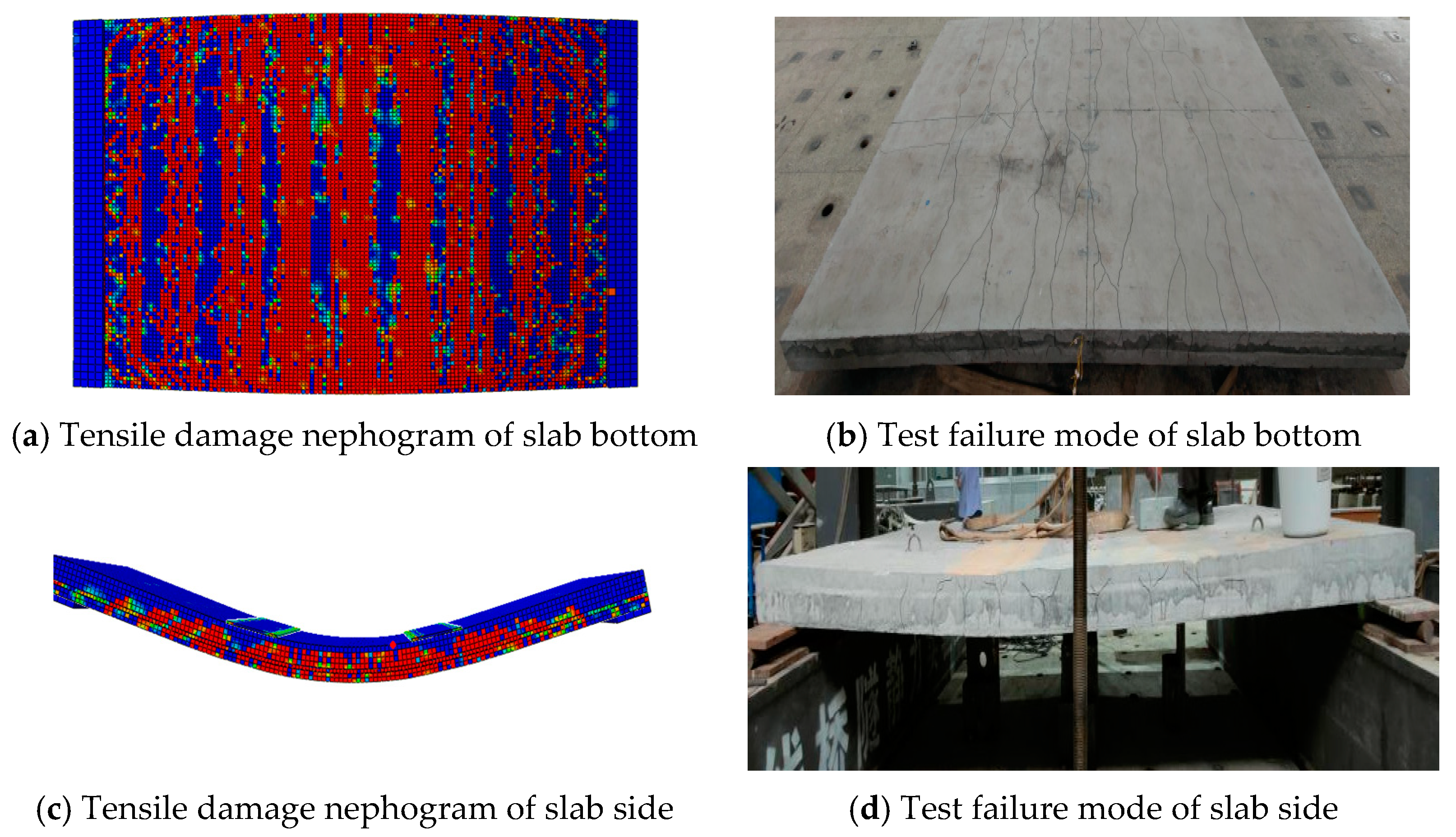
5.1. Damage Analysis of Sandwich Laminated Floor Slab

The damage and crack distribution of sandwich laminated floor slabs are closely related to the stress damage distribution, so it is necessary to carry out the stress damage analysis. As seen in Figure 18, the cracks at the bottom slab are mainly concentrated within the span of the loading point and are symmetrically distributed from the middle of the span to both ends. The crack direction is parallel to the short span of the sandwich laminated floor slabs. The cracks on the side of the slab gradually develop from the bottom to the top, with the inclination angle decreasing while passing through the sandwich layer. Moreover, the distribution of tensile damage at the bottom and side of the plate is roughly consistent with the crack location during the test. Therefore, the finite element simulation results can reflect the actual damage.

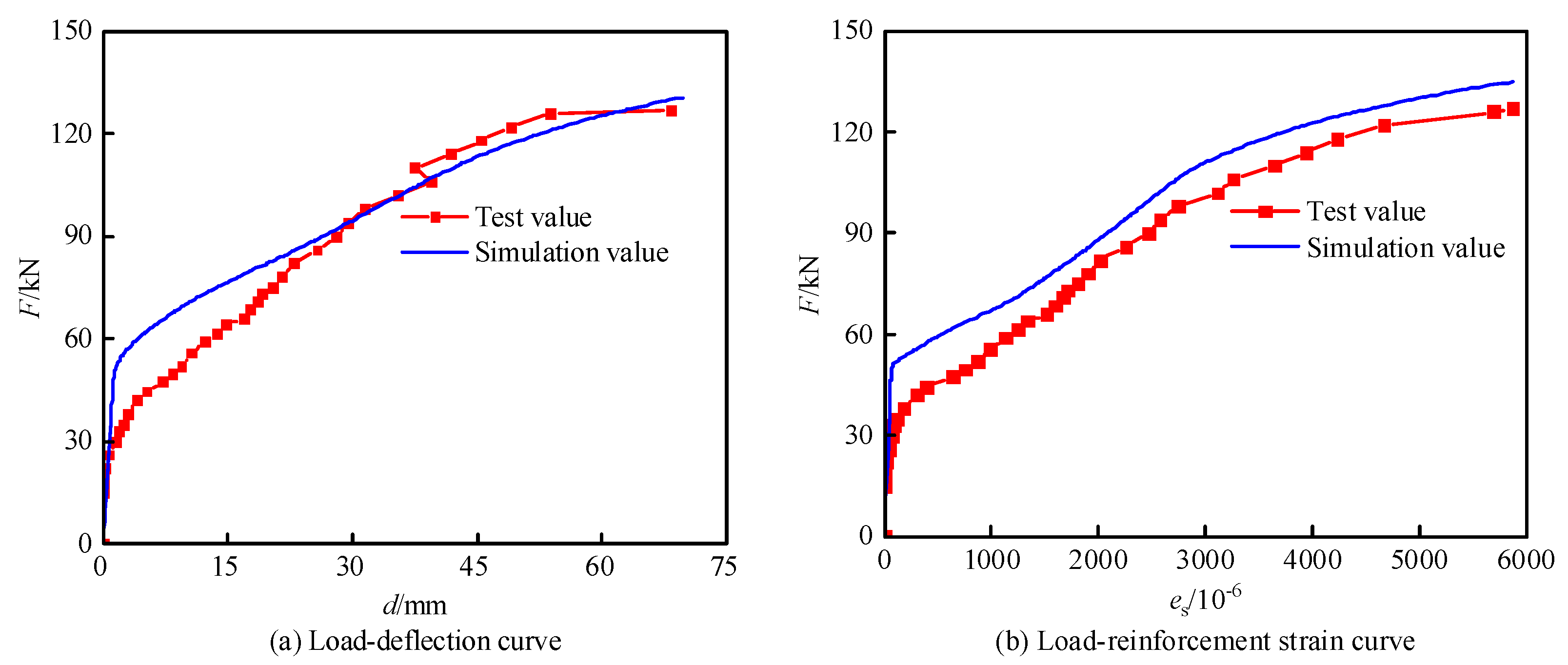
5.2. Comparative Analysis of Load-Deflection Curve, Load-Reinforcement Strain Curve, and Bearing Capacity

Figure 19 shows the comparison between the finite element simulation and the test curve, which indicates that the simulated results accord well with the measured results, so the finite element method can be used for deeper analysis. The experimental values of cracking load are slightly smaller than the simulated values, which is mainly due to incomplete constraints of combined interface and bond-slip between reinforcement and concrete. However, the influences of material difference, manufacturing error, and curing conditions are ignored during simulation calculation, which is assumed under the ideal conditions, and accordingly results in the deviation between the simulated and the measured values.
Table 6 shows the comparison of bearing capacity between the measured and the simulated value. The results show that the simulated values accord well with the measured values. The difference between the normal use load, yield load, and ultimate load of the specimen is 2%~16%. The root mean square error is 0.015, which indicates that the deviation between the simulated and the measured values between different characteristic loads is small. The deviation of cracking load is relatively large due to the discreteness of concrete properties and the deviation during manufacturing and loading. The simulation results reflect the test conditions well, especially the ultimate bearing capacity. Therefore, the finite element simulation method can be used to further analyze the mechanical performance of the sandwich composite floor.

5.3. Effect of Post-Cast Layer Concrete Strength

Concrete strength significantly influences the mechanical performance of the sandwich laminated floor slab. In order to further explore the influence of post-cast layer concrete strength on the normal use load and ultimate load of the specimen, the bearing performance under different post-cast concrete strength grades is compared and analyzed by numerical simulation. As shown in Figure 20, the load-deflection curves of the sandwich laminated floor slab with different concrete strength grades have the same variation trend, which shows an upward trend with the increase in concrete strength. The mid-span deflection of the same load decreases with the increase in concrete strength overall but is not significant. As the strength increases, the normal service load and ultimate load of the specimen gradually increase overall. When the concrete strength of the post-cast layer is C30, C35, and C40, the normal use load and ultimate load are the same at about 80 and 131 kN, respectively, and slightly increased to about 84 and 134 kN, respectively, when the concrete strength of the post-cast layer is C50 and C60. The tensile reinforcement firstly yields, and then the concrete is crushed, which is classified as an under-reinforced failure. The main reason is that during the period from the cracking to the ultimate bearing capacity, the post-cast layer concrete has not been damaged, and the load of the sandwich laminated floor slabs is borne by the tensile reinforcement at the bottom. The reinforcement ratio of the sandwich laminated floor slabs with different post-cast layer concrete strength is the same in the finite element simulation, so the difference in bearing capacity between the specimens is small. The effect of post-cast concrete strength can be ignored because of the small difference. Table 7 shows the effect of the concrete strength of the post-cast layer on the characteristic load.

6. Conclusions

The concrete sandwich laminated floor slabs with integrated thermal and sound insulation are proposed. The experimental research, theoretical analysis, and numerical simulation are carried out on two full-size specimens, and the major conclusions are as follows:
(1).
The whole bending failure process of the sandwich laminated floor slab can be divided into three stages: elasticity, cracking, and failure. The demarcation points are concrete cracking and steel yielding, respectively. The bearing capacity of the sandwich laminated floor slab is significantly improved with the increase in reinforcement ratio. The normal use load, yield load, and the ultimate load with a larger reinforcement ratio are increased by 54.55%, 52.94%, and 46.46%, respectively. When the reinforcement ratio is increased, the late stiffness and the structural integrity are significantly improved. Moreover, the mid-span deflection decreases significantly with the increase in reinforcement ratio, and the cracking expansion is also delayed.
(2).
The pure bending section of the sandwich laminated floor slab conforms to the plane-section assumption under the action of two-point symmetrical loads. The anti-sliding performance results show that the prefabricated and the laminated layer are fully composite before cracking, and the common bearing can be realized. The specimen is partially composite when reaching the ultimate state, with the slip effect on the superposition surface.
(3).
The simulated and measured results accord well, which has the same variation of failure mode, load-deflection, and load-reinforcement strain. The difference between the simulated and the measured values of the ultimate load is less than 5%, which verifies the feasibility and effectiveness of the finite element analysis method. Further extending the analysis, the effect of the concrete strength of the post-cast layer on the normal use and ultimate load is not significant and can be neglected.

Author Contributions

Conceptualization, P.L. and S.X.; methodology, S.X. and L.L.; software, S.X. and A.L.; resources, N.Z.; data curation, S.H.; writing—original draft preparation, S.X.; writing—review and editing, P.L. and L.L.; visualization, Y.W.; supervision, W.X.; project administration, Y.C.; funding acquisition, Z.Y. All authors have read and agreed to the published version of the manuscript.

Funding

This study was funded by the National Natural Science Foundation of China (grant numbers 52178182, 52108262, and U1934217) and China Railway Science and technology research and development plan project (grant numbers 2020-Major project-02, 2021-Major project-02, 2021-Key projects-11). Authors also have received research grants from the Natural Science Foundation of Hunan Province of China (2020JJ5982), Science and Technology Innovation Program of Hunan Province (2020RC4049), Science and Technology Development Project of Chenzhou Municipal Science and Technology Bureau (ZDYF2020218), Hunan Innovative Province Construction Special Project (2020GK4058), and National Science Foundation for Distinguished Young Scholars of Hunan Province (Grant No. 2022JJ10075).

Institutional Review Board Statement

Not applicable.

Informed Consent Statement

Not applicable.

Data Availability Statement

Not applicable.

Conflicts of Interest

The authors declare no conflict of interest.

References

  1. Huang, L.J.; An, Q.; Geng, L.; Wang, S.; Jiang, S.; Cui, X.P.; Zhang, R.; Sun, F.B.; Jiao, Y.; Chen, X.; et al. Titanium Matrix Composites: Multiscale Architecture and Superior High-Temperature Performance of Discontinuously Reinforced Titanium Matrix Composites. Adv. Mater. 2021, 33, 2170039. [Google Scholar] [CrossRef]
  2. Kueh, A.B.H. Buckling of sandwich columns reinforced by triaxial weave fabric composite skin-sheets. Int. J. Mech. Sci. 2013, 66, 45–54. [Google Scholar] [CrossRef]
  3. Soufeiani, L.; Ghadyani, G.; Kueh, A.B.H.; Nguyen, K.T.Q. The effect of laminate stacking sequence and fiber orientation on the dynamic response of FRP composite slabs. J. Build. Eng. 2017, 13, 41–52. [Google Scholar] [CrossRef]
  4. Wang, S.; Huang, L.J.; An, Q.; Jiang, S.; Zhang, R.; Geng, L.; Qu, S.X.; Peng, H.X. Regulating crack propagation in laminated metal matrix composites through architectural control. Compos. Part B Eng. 2019, 178, 107503. [Google Scholar] [CrossRef]
  5. Ding, K.W.; Zhang, Y. Study on Composite Slab Structure. Appl. Mech. Mater. 2012, 214, 311–314. [Google Scholar]
  6. Wang, L.; Zhang, H.Y. Summary of Study on Composite Concrete Slabs. Appl. Mech. Mater. 2013, 2544, 695–698. [Google Scholar]
  7. Wang, Q.J.; Huang, X. Configuration and construction technology of the heat preservation sound insulation mortar. Concrete 2012, 5, 108–110. [Google Scholar]
  8. Joseph, J.D.R.; Prabakar, J.; Alagusundaramoorthy, P. Precast concrete sandwich one-way slabs under flexural loading. Eng. Struct. 2017, 138, 447–457. [Google Scholar] [CrossRef]
  9. Sharkawi, N.; Baharun, A. Effect of Different Types of Paint to Residential Building. J. Civ. Eng. Sci. Technol. 2016, 7, 68–74. [Google Scholar] [CrossRef]
  10. Bai, F.; Davidson, J.S. Analysis of partially composite foam insulated concrete sandwich structures. Eng. Struct. 2015, 91, 197–209. [Google Scholar] [CrossRef]
  11. O’Hegarty, R.; Kinnane, O. Review of precast concrete sandwich panels and their innovations. Constr. Build. Mater. 2020, 233, 117145. [Google Scholar] [CrossRef]
  12. Xu, D.F.; Chen, L.M.; Tao, S.N.; Cheng, S.C.; Xiao, F. The Study on Connector’s Mechanical Performance of Energy-Saving Precast Concrete Sandwich Panel Structure. In Proceedings of the International Conference on Energy Development and Environmental Protection, Shenzhen, China, 17–18 September 2016; pp. 100–106. [Google Scholar]
  13. Chen, Z.H.; Zhoum, T.; Lium, H.B.; Chen, Y.H.; Wang, X.D. Experimental and Theoretical Study on Structural Behavior of Fabric Reinforced Concrete Sandwich Panels. Adv. Sci. Lett. 2011, 4, 663–668. [Google Scholar] [CrossRef]
  14. Zhu, M.C.; Liu, Z.R.; Chen, Z.H. Performance analysis of prestressed concrete sandwich composite slabs. China Concr. Cem. Prod. 2001, 5, 47–49. [Google Scholar]
  15. Li, Y.B.; Du, Y.Y.; Men, D.H. Analysis on bending performance of concrete sandwich panels. Build. Struct. 2015, 45, 91–95. [Google Scholar]
  16. Chen, H.Q.; Xie, J.; Zhu, L.M.; Dai, Z.Q. Experimental Research on Flexural Performance of Concrete Sandwich Two-Way Panels Reinforced by Bi-Steel. J. Tianjin Univ. 2009, 42, 35–40. [Google Scholar]
  17. Luo, B.; Huang, W.; Ma, X.; Li, B.; Zhou, W.C.; Ren, S.S. Flexural behavior of sandwich composite panels with core material of expanded polystyrene thermal insulation motar. J. Zhejiang Univ. Eng. Sci. 2019, 53, 2185–2196. [Google Scholar]
  18. Joseph, J.D.R.; Prabakar, J.; Alagusundaramoorthy, P. Flexural behavior of precast concrete sandwich panels under different loading conditions such as punching and bending. Alex. Eng. J. 2018, 57, 309–320. [Google Scholar] [CrossRef]
  19. Joseph, J.D.R.; Prabakar, J.; Alagusundaramoorthy, P. Insulated precast concrete sandwich panels under punching and bending. PCI J. 2019, 64, 68–79. [Google Scholar] [CrossRef]
  20. Ahmad, A.; Singh, Y. Flexural behavior of Expanded Polystyrene core Reinforced Concrete Sandwich Panels with different construction methods and end conditions. Structures 2021, 34, 2900–2911. [Google Scholar] [CrossRef]
  21. Tomlinson, D.; Fam, A. Analytical approach to flexural response of partially composite insulated concrete sandwich walls used for cladding. Eng. Struct. 2016, 122, 251–266. [Google Scholar] [CrossRef]
  22. Xu, M.G.; Wang, X.; Ding, Z.W. Development of Out-Wall External Thermal Insulation System Based on Rock-Wool. Appl. Mech. Mater. 2012, 174–177, 1589–1592. [Google Scholar]
  23. Qi, B.; Zheng, C.; Lv, H.; Li, C.Z.; Le, B.L.; Zhang, F. Research and Application of Phenolic Resin in the External Thermal Insulation and Fire Resistance Composite System. Eng. Plast. Appl. 2012, 40, 28–30. [Google Scholar]
  24. Wang, L.; Jin, L.Z.; Wang, D.W. Experimental study on flexural behavior of UHPC aminated plates with different superimposed surfaces. J. Build. Struct. 2018, 39 (Suppl. S2), 43–51. [Google Scholar]
  25. Zhang, X.Y. Experimental research on factors influencing the rigidity of concrete composite slab with steel bar truss. J. Hefei Univ. Technol. Nat. Sci. 2014, 9, 1122–1126. [Google Scholar]
  26. De Seixas Leal, L.A.A.; de Miranda Batista, E. Composite floor system with CFS trussed beams, concrete slab and innovative shear connectors. REM Int. Eng. J. 2020, 73, 23–31. [Google Scholar] [CrossRef]
  27. Cheng, J.Y.; Zhao, L.; Yang, J.J. Study on Short-Term Rigidity of Precast Composite Slab with Steel Truss and Concrete. Adv. Mater. Res. 2013, 639–640, 198–205. [Google Scholar]
  28. Huang, W.; Luo, B.; Li, B.; Xu, X.K.; Su, Y.J. Experiment on Flexural Behavior of Green Concrete Composite Slab with Different Structural Forms. J. Hunan Univ. Nat. Sci. 2019, 46, 35–44. [Google Scholar]
  29. Huang, H.L.; Wu, F.B.; Zhu, M.Q.; Zeng, C.J.; Lv, W.R. Influence of rib details on flexural behavior of concrete composite slab with precast prestressed ribbed panel. J. Build. Struct. 2015, 36, 66–72. [Google Scholar]
  30. Thanoon, W.A.; Yardim, Y.; Jaafar, M.S.; Noorzaei, J. Development of interlocking mechanism for shear transfer in composite floor. Constr. Build. Mater. 2010, 24, 2604–2611. [Google Scholar] [CrossRef]
  31. Chen, Z.H.; Wang, J.; Cui, X.T.; Jiang, J.Q.; Wang, Z.Y.; Qiu, H.F.; Huang, Z.Y. Field test study on bearing capacity of assembled concrete composite slab. New Build. Mater. 2020, 47, 49–52. [Google Scholar]
  32. Hao, M.J.; Zheng, W.Z.; Chang, W. Evaluating Stress-Strain Properties of Reinforcing Steel for Reinforced Concrete. Adv. Civ. Eng. Mater. 2020, 9, 283–297. [Google Scholar] [CrossRef]
  33. GB/T 50081-2019; Standard for Test Methods of Concrete Physical and Mechanical Properties. National Standard of the People’s Republic of China: Beijing, China, 2019.
  34. GB 50010-2010; Code for Design of Concrete Structures. National Standard of the People’s Republic of China: Beijing, China, 2010.
  35. Ma, X.; Huang, W.; Luo, B.; Zhang, J.R.; Xie, H.Q. Reviews of concrete composite slabs—Mechanical properties and design methods. Concrete 2020, 364, 129–133. [Google Scholar]
  36. Huang, J.Q.; Xu, Y.Y.; Huang, H.; Dai, J.G. Structural behavior of FRP connector enabled precast geopolymer concrete sandwich panels subjected to one-side fire exposure. Fire Saf. J. 2022, 128, 103524. [Google Scholar] [CrossRef]
  37. Lameiras, R.; Barros, J.A.O.; Valente, I.B.; Poletti, E.; Azevedo, M.; Azenha, M. Seismic behaviour of precast sandwich wall panels of steel fibre reinforced concrete layers and fibre reinforced polymer connectors. Eng. Struct. 2021, 237, 112149. [Google Scholar] [CrossRef]
  38. Ma, S.; Hou, D.F.; Bao, P.; Wang, D.T. Influence of alkali-resistant glass fiber on seismic performance of precast ceramsite concrete sandwich wall panels. Structures 2022, 38, 94–107. [Google Scholar] [CrossRef]
  39. Xu, G.L.; Xu, Q.; Wang, J.X.; Qi, H.; Bai, Y.S. Uniaxial elastic-plastic damage constitutive model and parameters of concrete. J. Guangxi Univ. Nat. Sci. 2016, 41, 332–338. [Google Scholar]
  40. Dai, Y.; Nie, S.F.; Zhou, T.H. Finite element analysis of hysteretic behavior of square steel tube confined steel reinforced concrete column steel frame ring beam joint. J. Jilin Univ. Eng. Technol. Ed. 2018, 48, 1426–1435. [Google Scholar]
Figure 1. Schematic diagram of sandwich laminated floor slab interlayer structure.
Coatings 12 01075 g001
Figure 2. Pouring diagram of sandwich laminated floor slab.
Coatings 12 01075 g002
Figure 3. Reinforcement diagram of sandwich laminated floor slab (unit: mm).
Coatings 12 01075 g003
Figure 4. Section diagram of sandwich laminated floor slab. (a) Section A-A of floor slab; (b) Section A-A of floor slab (unit: mm).
Coatings 12 01075 g004
Figure 5. Schematic diagram of combined stirrup rebar (unit: mm).
Coatings 12 01075 g005
Figure 6. Loading device and failure mode under compression.
Coatings 12 01075 g006
Figure 7. Schematic diagram of test device and loading (unit: mm).
Coatings 12 01075 g007
Figure 8. Loading mode diagram.
Coatings 12 01075 g008
Figure 9. Layout of measurement points for reinforcement strain gauges (unit: mm).
Coatings 12 01075 g009
Figure 10. Layout of measuring points of concrete strain gauge (unit: mm).
Coatings 12 01075 g010
Figure 11. Failure mode and crack distribution of DBD01.
Coatings 12 01075 g011
Figure 12. Failure mode and crack distribution of DBD02.
Coatings 12 01075 g012
Figure 13. The concrete strain distribution along the section height in the mid-span.
Coatings 12 01075 g013
Figure 14. Load-mid span deflection curve.
Coatings 12 01075 g014
Figure 15. Load versus strain curve of reinforcement.
Coatings 12 01075 g015
Figure 16. Distribution of shear force and strain.
Coatings 12 01075 g016
Figure 17. Finite element model of the specimen.
Coatings 12 01075 g017
Figure 18. Tensile damage nephogram and failure mode.
Coatings 12 01075 g018
Figure 19. Load-deflection curve and load-reinforcement strain curve.
Coatings 12 01075 g019
Figure 20. Load-deflection curve of specimens under different post-cast concrete strengths.
Coatings 12 01075 g020
Table 1. Detailed dimensions and reinforcement of sandwich laminated floor slabs.
Specimen NumberSize (mm)Transverse
Rebar
Longitudinal
Rebar
Face RebarStirrup RebarRebar Ratio ρ/%
DBD013600 × 2400 × 160ARH6@200ARH8@200C8@150A60.26
DBD02ARH8@1000.50
Table 2. Mechanical properties parameters of steel bars.
Reinforcing Steel Typefyk (N/mm2)fstk (N/mm2)Es (N/mm2)
CRB600H540600190,000
HRB400400540200,000
HPB300300420210,000
Table 3. Mechanical properties of concrete materials.
TypeMeasured Value of Compressive Strength of Prefabricated Layer (MPa)Measured Value of Compressive Strength of Laminated Layer (MPa)fc (MPa)Ec (MPa)
DB0149.248.726.832,500
DB0248.348.8
Table 4. Characteristic load of sandwich laminated floor slab.
TypePcr (kN)P1/200 (kN)Py (kN)Pu (kN)Pcr/PuPl/200/PuPy/Pu
DBD01136610212710.24%51.97%80.31%
DBD023910215618620.97%54.84%83.87%
Note: The characteristic loads of the sandwich laminated floor slab include the weight of the distribution beam.
Table 5. Composite working performance of sandwich laminated floor slabs.
Specimen NumberBefore CrackingAt Limit State
Mcs (kN·m)Mcr (kN·m)|(McsMcr)/Mcs|Mut (kN·m)Mun (kN·m)Muf (kN·m)Mut/Muf
DBD017.36.96.1%71.812.5128.755.7%
DBD0222.022.52.1%105.115.5169.562.0%
Noted: Mcs is the measured cracking moment, and Mcr is the calculated cracking moment.
Table 6. Comparison between simulated and measured values of specimen bearing capacity.
Specimen NumberCharacteristic LoadMeasured ValueSimulated Values|Simulated Values-Measured Value|/Measured Value
DBD01Pcr (kN)13240.46
P1/200 (kN)66790.16
Py (kN)1021090.06
Pu (kN)1271300.02
Table 7. Effect of concrete strength of post-cast layer on the characteristic load.
Concrete Strength of the Post-Cast LayerC30C35C40C50C60
P1/200 (kN)8080808385
Pu (kN)131131132134134
Publisher’s Note: MDPI stays neutral with regard to jurisdictional claims in published maps and institutional affiliations.

