Article

Simulation Analysis of Organic–Inorganic Interface Failure of Scallop under Ultra-High Pressure

1
School of Food Engineering, Harbin University of Commerce, Harbin 150028, China
2
School of Light Industry, Harbin University of Commerce, Harbin 150028, China
3
Research Center for Higher Education Development, Harbin University of Commerce, Harbin 150028, China
4
College of Food, Northeast Agricultural University, Harbin 150030, China
5
Research Center for Composite Materials and Structures, Harbin Institute of Technology, Harbin 150000, China
*
Author to whom correspondence should be addressed.
Coatings 2022, 12(7), 963; https://doi.org/10.3390/coatings12070963
Submission received: 14 May 2022 / Revised: 2 July 2022 / Accepted: 4 July 2022 / Published: 7 July 2022
(This article belongs to the Special Issue Manufacturing and Surface Engineering III)

Abstract

:
Shell is a typical biomineralized inorganic–organic composite material. The essence of scallop deshelling is caused by the fracture failure at the interface of the organic and inorganic–organic matter composites. The constitutive equations were solved so that the stress distributions of the adductor in the radial, circumferential, and axial directions were obtained as σr = σθ = P, σz = 2(2 − ν)P/(2ν − 1), and the shear stress was τzr = 0. Using the method of finite element simulation analysis, the stress distribution laws at different interface states were obtained. The experimental results show that when the amplitude is constant, the undulation period is smaller than the diameter of the adductor or the angle between the bus of the adductor, and the reference horizontal plane gradually decreases, so the interface is more likely to yield. After the analysis, the maximum stress for the yielding of the scallop interface was about 247 MPa, and the whole deshelling process was gradually spread from the outer edge of the interface to the center. The study analyzed the scallop organic–inorganic material interface from the perspective of mechanics, and the mechanical model and simulation analysis results were consistent with the parameter optimization results, which can provide some theoretical basis for the composite material interface failure and in-depth research.

1. Introduction

The main edible part of scallops with a high nutritional value and high demand is the adductor muscle. It is difficult to realize the industrial production of shelling scallops with mechanical processing because the adductor muscle is relatively strong. At present, the widely used artificial peeling method has high cost and poor sanitation. The shelling technology of scallops has also attracted the greater attention of researchers [1,2]. With the development in ultra-high pressure technology, when scallops are sterilized and processed using ultra-high pressure technology, it was found that the closed-shell muscle of scallops treated with ultra-high pressure could be peeled off from the shell intact. The research results showed that the closed-shell muscle could be completely detached from the shell under 300 MPa pressure [3,4], and the freshness, color, and taste of the closed-shell muscle did not change much. Therefore, ultra-high pressure deshelling technology enables the industrial production of scallops and other aquatic products, reduces the processing costs, and improves the processing efficiency and sanitation [5,6,7].
The adductor muscle of the scallop is the key part that connects the flesh to the shell, which creates a tight force between the two shells. Experiments have shown that it takes a pull of 20 kg to peel the shell off. In recent years, the connection mechanism and the structural characteristics of the interface between the shell and shell flesh have attracted extensive attention from researchers. Seung [8] et al. found the existence of a muscular prismatic layer connecting the shell apex and the closed-shell muscular scar of the oyster, which is a multilayered composite structure composed of minerals and organic matter. Song [9] et al. found that the main composition of the shell was 95% mineral and 5% organic matrix, and the organic matter contained more than 40% of collagen fiber, which are important for shell biomineralization. Zhao [10] et al. found that the shell was a highly ordered natural nanocomposite composed of calcium carbonate crystal and organic matter, and that there was an organic film connecting the muscle and shell calcium carbonate crystals. Liao [11] et al. found that there was a thin organic film between the shell and obturator muscle of shellfish, making shellfish a connection system of organic-membrane–inorganic material. The scallop closed-shell muscle can be approximated as a cylindrical, viscoelastic solid fibrous material and the main component is adduction, which has a modulus of elasticity relatively close to that of an elastic fiber. Scallop shells are natural nanoscale composite biomaterials consisting of 95% calcium carbonate crystals and 5% matrix proteins, the presence of which substantially improves the mechanical properties of scallop shells [12,13]. The mechanical properties of scallop shell materials are different from those of adductor muscle materials, which belong to typical mineral protein biological composites. Faber believes that it is difficult to control the deformation state and quantify the highly nonlinear and time-dependent tissue response of the brain tissue in biomechanical tests due to its ultrasoft and biphasic characteristics. She comprehensively analyzed its mechanical properties based on the advantages of nonlinear continuum mechanical modeling and finite element simulation [14]; Sciarretta et al. used gelatin agar material and distilled water to construct a heterogeneous soft tissue equivalent phantom, and simulated soft tissue deformation with nonlinear finite element analysis. The results showed that finite element analysis could accurately predict the tissue simulation and elastic reconstruction of soft tissue modeling [15]. The shelling of scallops can be considered as the mechanical behavior of bimaterial interface fracture [16,17,18]. Under the action of external pressure, the closed-shell muscle will be deformed, resulting in the Mises stress at the interface reaching the interfacial strength, forming cracks and separation [19]. Von Mises stress-based failure criteria were employed in our finite element method (FEM) simulations. This study can effectively explain the shelled mechanism of scallops under ultra-high pressure, which will provide technical support for the industrialization of aquatic products processing and a theoretical basis for the study of mechanical properties and the application of an organic–inorganic composite interface.

2. Mechanical Model of Failure at the Interface of Organic–Inorganic Composites of Scallops under Ultra-High Pressure

2.1. Simplified Model Analysis of the Scallop Organic–Inorganic Composite Interface

Shell is a natural organic and inorganic composite material composed of a large amount of CaCO3 and traces of organic matter. Compared with natural CaCO3 crystals, shell has superior mechanical properties and strength [20,21]. The research results show that shells are anisotropic and the bearing capacity perpendicular to the shell surface and parallel to the axis is stronger than that parallel to the shell surface and perpendicular to the axis [22]. The connection between the shell and the shell flesh is mainly based on the closed-shell muscle, which is mainly composed of protein-based organic matter and is generally cylindrical in shape. The Young’s modulus of the closed-shell muscle is much smaller than that of the scallop shell [23,24]. Therefore, under the action of ultra-high pressure, deformation mainly occurs at the position of the obturator muscle and the deformation of the scallop shell is very small. Compared to the shape variable of the scallop obturator muscle, the shell deformation can be ignored, so it can be considered that the scallop shell has no deformation under ultra-high pressure [25]. We can simplify the scallop muscle into a cylinder, and the specification parameters and mechanical model should be marked with cylindrical coordinates. Assume that the obturator muscle of a scallop is perpendicular to the shell and the contact surface between the obturator muscle and the shell is flat. The cylindrical coordinate system is established on the obturator muscle, as shown in Figure 1a,b. The distance of the projection of any point in space on the XOY plane to point O is r, the angle is θ, and the distance from the Z-axis is ρ.

2.2. Construction of a Failure Mechanics Model for the Organic–Inorganic Interface of Scallops

2.2.1. Scallop Organic Interface Material Force Analysis

When the scallop is subjected to an external load P, only the closed-shell muscle is deformed, so the closed-shell muscle is divided into a number of small microelements and one of them was taken as the object of study. The forces in the Z, R, and θ directions are shown in Figure 1c.

2.2.2. Establishment of the Ontological Equations for Scallop Organic Interfacial Materials

According to Figure 1, it is assumed that the obturator muscle of scallops is a cylinder perpendicular to the surface of the shell. In this case, all physical quantities of the obturator muscle are independent of the toroidal coordinates θ, all particles on the obturator muscle can only move in the r–Z plane, and the shape transformation of the obturator muscle is symmetric to any radial r–Z plane. According to the above characteristics, the stress problem of the scallop muscle and shell can be transformed into an axisymmetric problem for analysis. According to the stress characteristics of an axisymmetric body, its shear components τ and τ are both zero, and its non-zero stress components are only σr, σθ, σz, and τrz [26,27]. The equilibrium differential equation can be simplified as follows:
σ r r + τ z r z + σ r - σ θ r + f r = 0 τ r z r + σ z z + τ r z r + f z = 0

2.3. Mechanical Model of Scallop Organic–Inorganic Composite Interface Failure under the Action of Ultra-High Pressure

According to the process and principle of the action of shell and closed-shell muscle during the action of ultra-high pressure, we established the boundary conditions for the mechanical changes of the shell and closed-shell muscle as follows.
σ r ( r = r 0 ) = P   ( r   is   any   value )
According to the results of the simplification of the structure of the scallop shell and the obturator muscle, we attributed the connection between the scallop shell and obturator muscle to an axisymmetric problem in the cylindrical coordinate system [28]. For the differential equations of axisymmetric problems of this kind, without considering the physical force (fr = 0, fz = 0), Rafu (Love) and the displacement function ψ(r, z) are solved analytically [29,30,31]. We considered that the radial displacement of the scallop closed-shell muscle was finite when the value of r was leveled off to zero. The stress distribution in the closed-shell muscle is as follows:
σ r = P σ Θ = P σ z = 2 ( 2 v ) P 2 v 1 τ z r = 0
where σr, σθ, σz are the stress in the radial direction, circumferential direction, and axial direction; ν is Poisson’s ratio; τrz is the shear stress; P is the external pressure.
According to Equation (3), when the outer surface of the scallop muscle is subjected to ultra-high pressure P, the radial stress σr and the annular stress σθ of the scallop muscle are constant P, the axial stress σz is constant 2 ( 2 υ ) P 2 υ 1 , and the shear stress τzr is 0.
According to Equation (3), when the obturator muscle of scallop is subjected to an ultra-high pressure P, the values of the stress in all directions are in the ideal state and in contact with the plane of the obturator muscle and the shell, but the interface between the shell and the obturator muscle of the real scallop is not smooth. At the same time, the positional relationship between the obturator muscle and the shell of the scallop is not necessarily vertical, so certain angles will be generated in the process of deformation. Under ultra-high pressure, the distribution of stress and strain at the internal and interfacial scallop shell muscles will be more complex than under ideal conditions. The model of the contact interface cannot be simplified to an axisymmetric problem, which makes the modeling and solution process much more complex than the problem of perpendicular contact between the scallop closed-shell muscle and the shell plane. The analytic solution cannot be obtained by using the differential equation and Love displacement function. Therefore, the finite element analysis can be used to obtain the distribution law of anisotropic stress when the scallop muscle and shell contact non-vertically under the complex surface.

3. Simulation Analysis of Organic–Inorganic Interface Failure of Scallops under Ultra-High Pressure

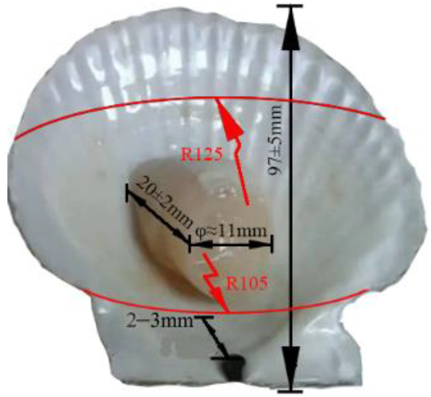
Due to the complexity of the scallop structure, it is difficult to obtain the analytical solution by solving the partial differential equation of the problem. In order to study the distribution of stress and strain, it is necessary to use the numerical method to solve the partial differential equation of the above problems, and the FEM provides a means in which to study complex mechanical problems. By dividing the mechanical model of the problem into finite cells and setting the contact relations, the loads, and boundary conditions between different regions, the numerical solution to the corresponding problem can be obtained [32,33,34]. To fix the whole scallop FEM model, the edges of shell are fixed during the simulations as a boundary condition. The external pressure is applied on the surfaces of the whole model to release the loads in the experiment. The solution of the problem obtained by the finite element method is an approximate solution, which differs from the exact solution, but it can visualize the basic situation of the stress and strain distribution of the object under study, which is of some significance as a guide for practical problems. According to the experimental requirements, the selected scallop closed-shell muscle diameter was φ ≈ 11 mm, the length was h ≈ 20 mm, and the thickness of the scallop shell was t ≈ 0.5 mm. In the FEM model, the scallop muscle was simplified as a cylinder part with a diameter of 11 mm and a length of 20 mm. The real shell structure is complex and some features were ignored when the FEM model was built, for example, the grains on the outer surface were not considered. The detailed geometry parameters are shown in Figure 2.
As it is difficult to measure the real mechanical properties of the scallop adductor muscle and shell, the mechanical property parameters can be determined by referring to the relevant literature in the analysis [35,36], which is shown in Table 1. A linear elastic material model was employed for both the scallop muscle and shell. This may not accurately reflect the mechanical behavior of the materials because nonlinear properties such as plasticity, viscosity, and anisotropy will have an effect on the stress level and distribution during the external load. For example, when the materials are considered as an elastic–plastic model, the highest stress will decrease compared to the elastic model at the same strain. Therefore, this should be considered in future study when conducting more mechanical tests of the scallop muscle and shell.
Based on the analysis of the structure of the inner surface of the shell, it was shown that there are a small number of small nanopores at the scallop interface at the location of the closed-shell muscle scar. This suggests that a small number of fibrous structures protrude from the scallop closed-shell muscle into the nanopores on the scallop surface, binding the closed-shell muscle firmly to the scallop shell. Currently, it is limited by the experimental equipment and methods. The mechanical properties and parameters of the interface between the closed-shell muscle metashell have not been studied and reported, so in the simulations in this paper, we considered the closed-shell muscle and the scallop shell as bound constraints at the contact position (the interface stiffness was very large), and used this condition to solve for the stress distribution at the interface.

3.1. Influence of the Angle between the Organic–Inorganic Interface Materials of Scallops on the Stress Distribution

Stress Distribution of Organic–Inorganic Composites of Scallops in Vertical Contact with Smooth Surfaces

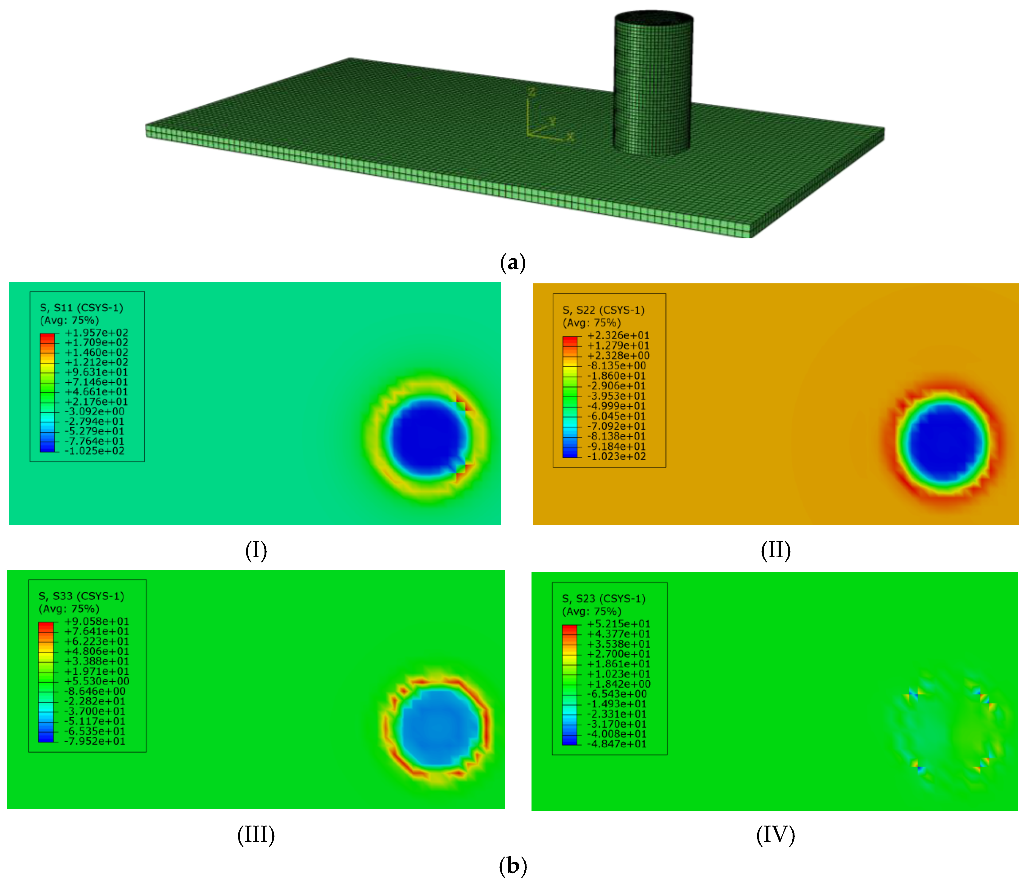
In order to compare with the solution in Section 2.3, the stress components of the scallop closed-shell muscle when it was perpendicular to the shell were first analyzed by finite element analysis, meshing, and stress distribution clouds, as shown in Figure 3.
As can be seen from Figure 3b, the distribution of the radial and circumferential stresses at the interface between the closed-shell muscle and the shell of the scallop was not uniform, which is due to the fact that the Young’s modulus of the scallop shell is much larger than that of the closed-shell muscle. The scallop shell at the interface limits the deformation of the closed-shell muscle, resulting in a lower stress level than the analytical solution (Equation (3)). Meanwhile, the distribution of stresses is no longer constant, for example, for the radial stress component r, as shown in Figure 3(bI), the distribution was tensile in the outer part, with a maximum tensile stress of 196 MPa, and compressive in the middle part, with a maximum compressive stress of 103 MPa. Similar distributions exist for the circumferential and axial stress components. For the shear stress component τzr is basically zero. As previously mentioned, this simulation provides a first insight into the stress distribution at the interface of the scallop muscle and shell, which is not accurate when considering the nonlinear mechanical properties.

3.2. Effect of the Organic–Inorganic Interface State on Yield Stress Distribution of Scallop

3.2.1. Stress Distribution of the Organic–Inorganic Interface of Scallop with Angular Contact

Suppose the angle between the scallop closed-shell muscle and the shell contact interface position is α. At this time, the scallop structure is simplified to establish the model as shown in Figure 3a. When a structure is in a complex spatial stress state, it is not possible to judge whether the material has yielded and entered plastic deformation from the stress component in one direction alone. The expression of equivalent stress (i.e., Mises stress) judgment in a rectangular coordinate system is:
σ mises   = 1 2 ( σ x 2 σ y 2 ) + 1 2 ( σ y 2 σ z 2 ) + 1 2 ( σ z 2 σ x 2 ) + 3 ( τ x y 2 + τ y z 2 + τ z x 2 )
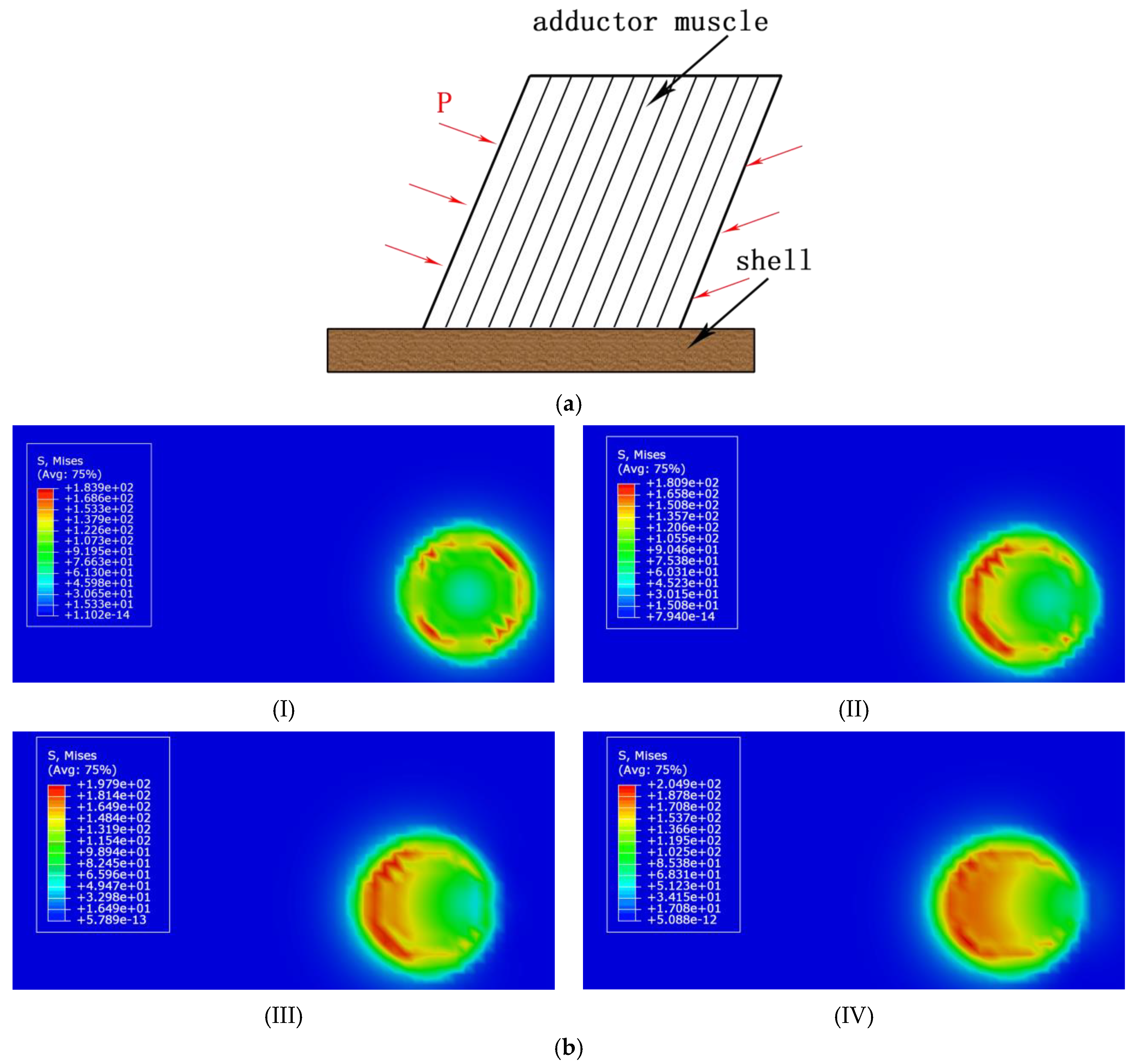
In order to investigate whether the interface between the closed-shell muscle and the scallop shell interface was subjected to yielding damage under ultra-high pressure external loading, we introduced Mises stress to study the stress distribution at the interface. Although there are no corresponding experimental results to provide the mechanical properties (such as yield strength, fracture strength, etc.) of the interface between the closed-shell muscle and the scallop shell, the Mises stress distribution at the interface given by the finite element simulation results can give the location where yielding and damage may occur at the interface, and the stress distribution cloud diagram is shown in Figure 4b.
From Figure 4(bI), it can be found that the maximum Mises stress was 184 MPa when the angle α = 90° between the closed-shell muscle and the shell of the scallop, which is located near the outer part of the closed-shell muscle. This value will vary when considering the nonlinear property of the materials. For example, when the plasticity is introduced, the maximum stress level will decrease after the materials are yielded. The Mises stress in the middle part is about several tens of MPa, which indicates that the interface between the closed-shell muscle and the scallop shell will first yield and break down on the outer side, and slowly spread to the middle of the interface when the scallop is under ultra-high pressure conditions. In practice, the angle between the closed-shell muscle and the scallop shell is difficult to measure, so we investigated the effect of the variation in the angle on the Mises stress distribution at the interface under the same pressure conditions (P = 200 MPa), as shown in Figure 4(bII–bIV). The results showed that the axial symmetry of the Mises stress distribution disappeared with the increase in the angle and the Mises stress was larger at the interface at the angle greater than 90°, while it was smaller at the interface at the other side. The maximum Mises stress at the interface increased from 184 MPa to 205 MPa with the decrease in the angle, suggesting that the smaller the angle between the obturator muscle and the scallop shell, the easier the interface separation is under the same external ultra-high pressure condition.

3.2.2. Influence of Surface Undulation Degree on the Stress Distribution of Scallop Shell

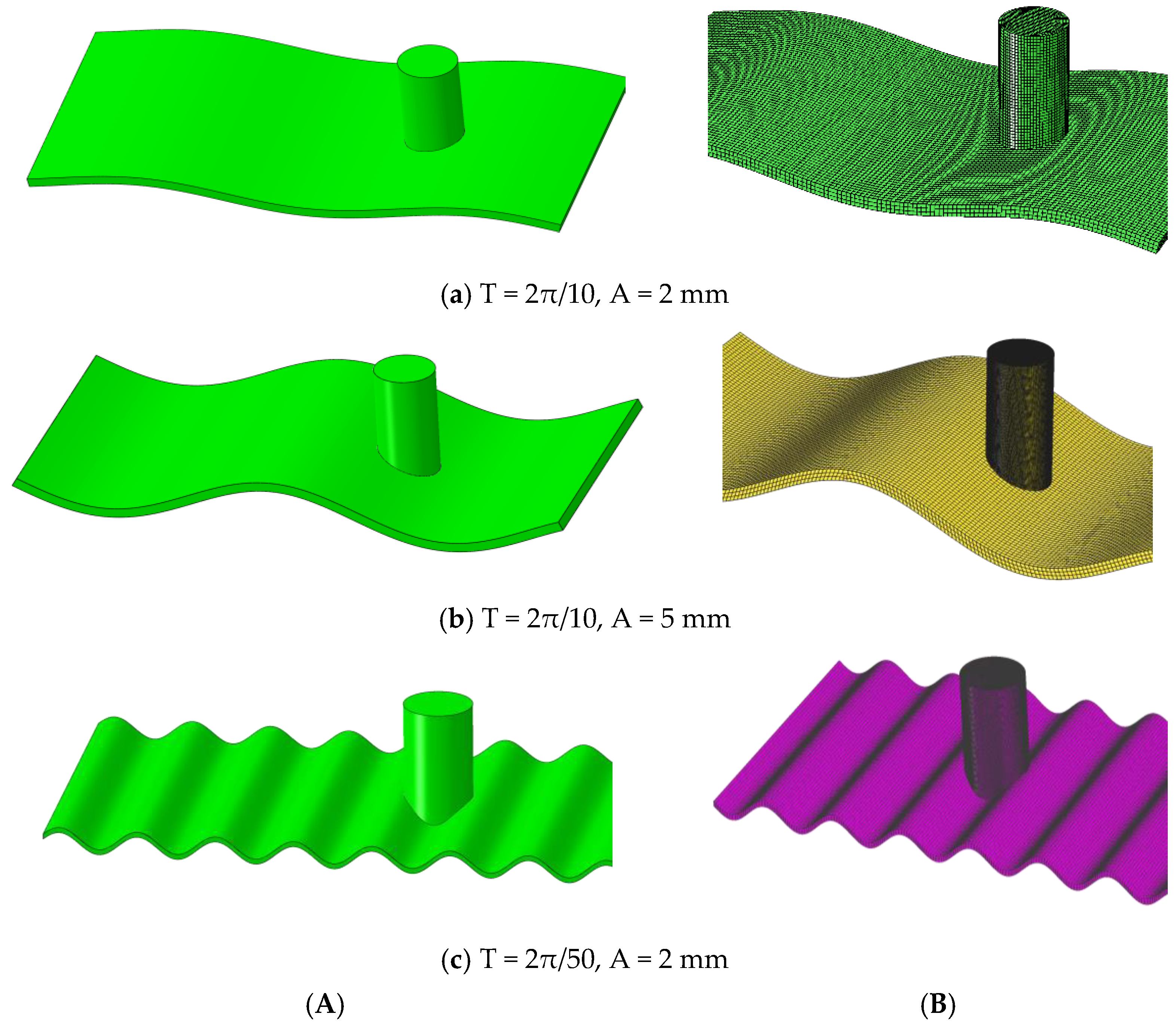
The surface of the scallop shell is not a flat structure and generally has undulations. In order to study the influence of the undulation of the scallop shell surface on the interface stress distribution, a non-planar simplified model was established, as shown in Figure 5A. We used trigonometric functions to express the undulation state of the scallop shell surface. According to the finite element analysis requirements, the established model was meshed for simulation analysis and the results of the meshing are shown in Figure 5B.
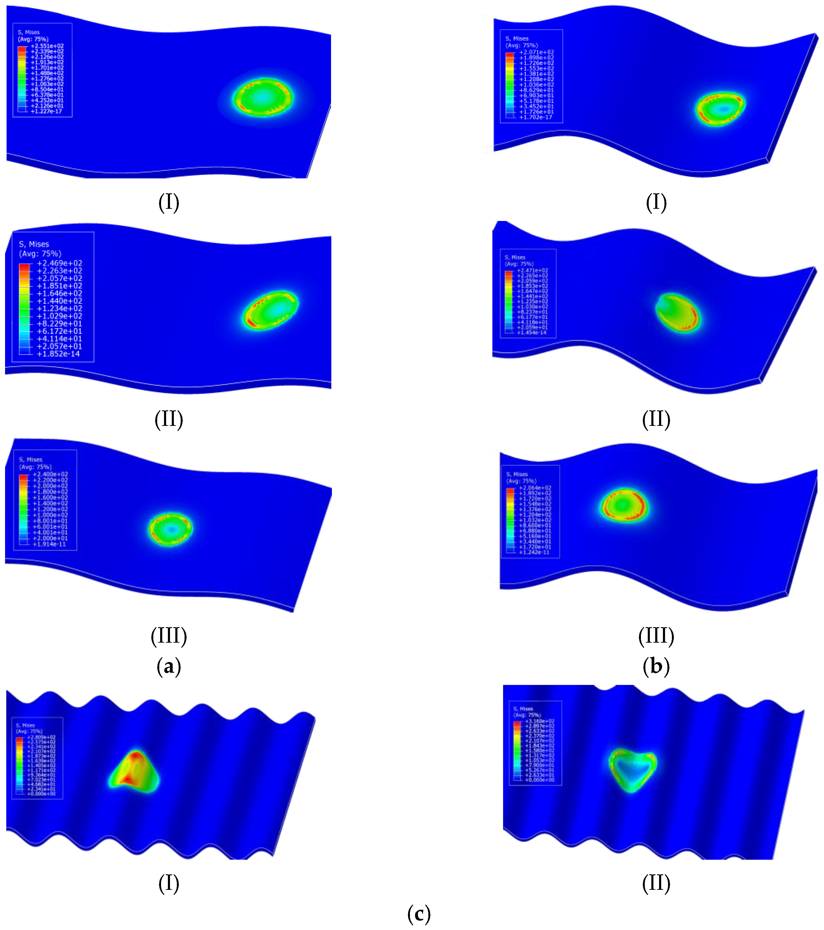
Under different periods and amplitude conditions, the Mises stress distribution at the location of the interface between the adductor muscle and the shell of the scallop is shown in Figure 6.
As can be seen from Figure 6, when the period of the scallop shell undulation was larger than the diameter of the closed-shell muscle, the amplitude was 2 mm. The maximum Mises stress in the closed-shell muscle at different positions did not vary much and was approximately 247 MPa. When the amplitude became 5 mm and the closed-shell muscle was at the wave peak and trough positions, the maximum Mises stress at the interface was about 205 MPa. The closed-shell muscle was at the middle of the wave crest and trough. The maximum Mises stress at the interface was larger, which was about 247 MPa.
By comparing the stress distribution clouds shown in Figure 5, it can be seen that the maximum Mises stress at the interface increased significantly when the period of undulation was smaller than the diameter of the closed-shell muscle at constant amplitude. This indicates that when the period of undulation of the scallop shell surface is smaller than the diameter of the closed-shell muscle, it leads to the interface being more susceptible to yielding and fracture damage.

4. Structural Stress Distribution at the Organic-Inorganic Interface of Scallops

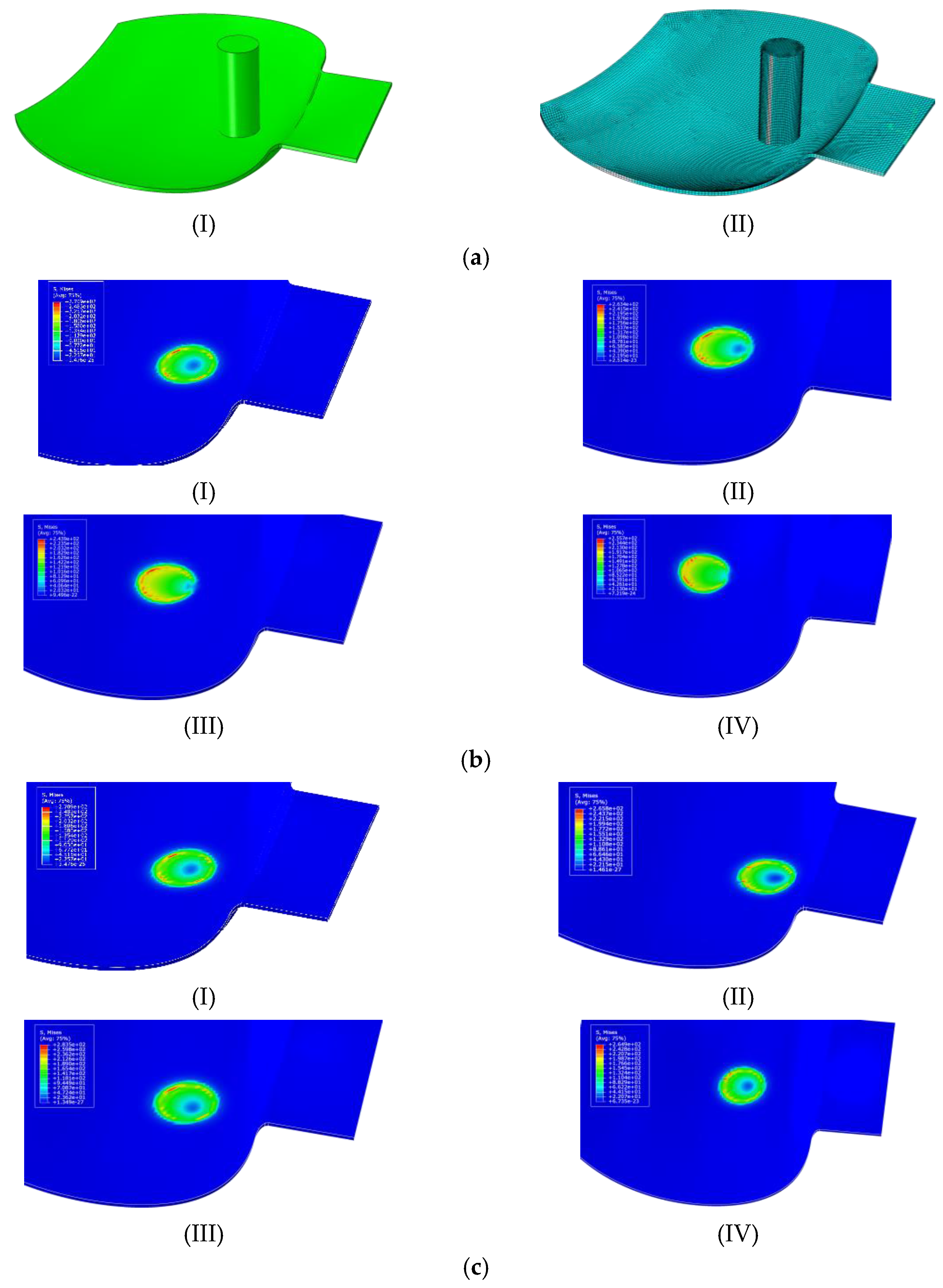
The models used for the above simulation results are ideal to study the interface stress distribution in a realistic scallop shell structure under the action of ultra-high pressure. We constructed a more realistic simplified model of the scallop shell structure and meshing, as shown in Figure 7a. Due to the complexity of the scallop shell surface, we simplified the structure and did not consider the surface undulations.

4.1. Influence of the Scallop Interface Material Clamping Angle on the Interface Stress Distribution

The stress distribution clouds of the scallop closed-shell muscle connected with the shell at different angles are shown in Figure 7b. From Figure 7b, it can be seen that as the angle between the adductor muscle and the reference horizontal plane becomes smaller, the Mises stress at the interface showed a trend of first decreasing and then increasing. This may be due to the fact that the scallop shell structure we constructed has a certain angle between itself and the reference horizontal plane, which is relative to the ideal flat scallop shell structure. In the real scallop shell structure, the maximum Mises stress at the interface is greater, which means that in the real scallop shell structure, the interface between the scallop closed-shell muscle and the shell is more prone to yielding and fracture damage under the action of ultra-high pressure.

4.2. Influence of Relative Position of Scallop Interface Material on Stress Distribution

When the scallop closed-shell muscle forms an interface with the shell, in addition to the angle between the closed-shell muscle and the reference horizontal plane having an effect on the stress distribution, the position of the closed-shell muscle on the shell surface may also have an effect on the stress distribution at the interface location. The stress clouds generated at different locations are shown in Figure 6c. From the analysis of Figure 6c, it can be seen that the Mises stress distribution and maximum value of the interface did not vary much with the different positions of the closed-shell muscle bond. This indicates that the relative position of the interface formed by the closed-shell muscle and the shell on the shell is different, which has little effect on the effect of scallop decoupling. In summary, the maximum yield stress required for scallop shell removal is related to the angle between the reference horizontal surfaces of the scallop shell closing muscles and the smoothness of the interface. The larger the angle of the interface and the more convex and uneven the interface is, the easier the interface is to yield and the easier it is to dehull. As a result of the simulations, the maximum yield stress required for shell removal was 247 MPa, which is due to the fact that under the pressure of 200 MPa, the continuity of the organic matter film on the inner surface of the shell at the scallop interface is broken. The stress concentration formed at the scallop interface and the organic matter structure between the minerals changed, breaking the covalent bonding between the interfacial closed-shell muscle and the shell. At the same time, the organic matter precipitation under ultra-high pressure also loosened the minerals, which, together with the tensile force generated by the interfacial closed-shell muscle between the two shells, caused the fibers in the shell to be pulled out. The predicted results of this model were closer to the experimental results [37], and the developed model has some scientific and reliability.
From previous studies, it is known that the micro-structures of scallop muscle and shell are complex and thus the mechanical properties are nonlinear [38,39]. The scallop muscle consists of fibers that have directional-dependent mechanical properties, while the scallop shell should also be considered as a composite material. In order to make the FEM simulations more accurate, the mechanical tests should be performed on the scallop muscle and shell to obtain the nonlinear behavior such as anisotropy, viscoelasticity, etc. These nonlinear mechanical properties will have an effect on the stress level and distribution at the interface during the high external pressure. At the same time, it is noted that the interface structure between the scallop muscle and shell are more complex, with collagen fibers inserting into the pit structure of the scallop shell surface, which plays an important role in maintaining the quality of the interfacial connection and strength [40]. These detailed structures should be investigated in the experiment and the corresponding mechanical properties should be tested in future study.

4.3. The Mechanism of Scallop Organic–Inorganic Interface Fracture Failure under Ultra-High Pressure

The scallop is a whole formed by connecting the two sides of the shell through the closed-shell muscle. During the ultra-high pressure process, the α-helical structure of protein in the scallop closed-shell muscle fiber is reduced, the fiber elasticity is weakened, the β-folded structure is increased, the dihedral angle of Ca atom is increased, and the hydrogen bond formed by the oxygen atom in the C=O group is broken, which makes the fiber elongate, and tension is generated between the shell and the closed-shell muscle. Under the action of external force, the difficulty of scallop shell removal is reduced. The dissolution of Ca2+ in the scallop shell minerals under the action of ultra-high pressure weakens the denseness of inorganic matter. The denaturation of organic matter between minerals under ultra-high pressure destroys the original stable “brick-mud” structure of the shell, changes the interaction force between the scallop and obturator muscle, and makes the scallop easier to molt [37,38]. Under ultra-high pressure, the denaturation of the organic membrane between the scallop and obturator muscle occurs, which changes the original uniform stress state of the interface and weakens the connection between the obturator muscle and shell meat. According to the observation and mechanical analysis of the scallop shell surface, the inner surface of the scallop is a non-smooth surface and the degree of undulation of the inner surface is smaller than the diameter of the closed-shell muscle. Compared with bivalve shellfish with a smaller closed-shell muscle, scallops are more likely to yield at the interface under the action of ultra-high pressure, which means that scallops can be decapitated with a relatively small ultra-high pressure force.

5. Conclusions

According to the force analysis results, the different positions of the organic–inorganic interface of the scallop have less influence on the stress distribution. When the interface materials are angularly bonded, the smaller the angle, so it is easier for the interface to yield and deshell. When the surface amplitude of the inorganic interface is constant and the undulation period is smaller than the diameter of the closed-shell muscle, the interface is more likely to yield and produce fracture damage. The maximum yield stress of 247 MPa for scallop decapitation was relatively close to the study results. Therefore, the established mechanical model and simulation analysis results are scientifically feasible. In this study, the elastic model was considered in the FEM simulations due to the limitation of the experimental tests. The nonlinear mechanical properties as well as the complex structures should be tested and employed in future FEM simulations to obtain more accurate results regarding the interfacial failure between the scallop muscle and shell.

Author Contributions

Conceptualization, X.G.; methodology, J.C.; software, N.X.; validation, H.Z.; formal analysis, J.W.; resources, J.C.; data curation, X.Z.; writing—original draft preparation, X.G.; writing—review and editing, Y.Z.; supervision, H.Z.; project administration, J.C.; funding acquisition, Z.S. All authors have read and agreed to the published version of the manuscript.

Funding

This research work was supported by the National Science and Technology Support Plan Fund (2016YFD0400301); the discipline team of food based functional active packaging of the Northeast Agricultural University (54941112), and the project of the National Natural Science Foundation of China (52002099).

Institutional Review Board Statement

Not applicable.

Informed Consent Statement

Not applicable.

Data Availability Statement

The data presented in this study are available in this article.

Conflicts of Interest

The authors declare no conflict of interest.

References

  1. Inglis, S.D.; Kristmundsson, A.; Freeman, M.A.; Levesque, M.; Stokesbury, K. Gray meat in the Atlantic sea scallop, Placopecten magellanicus, and the identification of a known pathogenic scallop apicomplexan. J. Invertebr. Pathol. 2016, 141, 66–75. [Google Scholar] [CrossRef] [PubMed]
  2. Zhou, Y.L.; Zheng, Y.; Liu, H.H.; Zhang, Q.; Song, Y.; Tian, Y.Y.; Liu, J.R. Activity and characteristics of superoxide dismutase in adductor muscle of live dry-storaged yesso scallop Patinopecten yessoensis. J. Dalian Ocean. Univ. 2018, 33, 651–657. [Google Scholar] [CrossRef]
  3. Gong, X.; Chang, J.; Li, D.T.; Sun, Z.H. Effect of ultrahigh pressure on the structure of scallop adductor muscle. Food Sci. 2021, 42, 87–93. [Google Scholar] [CrossRef]
  4. Zhang, Y.J.; Zhang, S.M.; Cao, P.L. The polypeptide in Chlamys farreri can protect human dermal fibroblasts from ultraviolet B damage. Chin. J. Oceanol. Limnol. 2005, 23, 357–362. [Google Scholar] [CrossRef]
  5. Song, Y.; Zhang, Q.; Zhou, Y.L. Protein distribution and physicochemical properties in striated muscle and smooth muscle of Patinopecten yessoensis. J. Fish. China 2017, 41, 357–362. [Google Scholar] [CrossRef]
  6. Kennedy, V.S.; Newell, R.I.E.; Eble, A.F. Process of Eastern Oyster: Crassostrea Virginica; University of Maryland Sea Grant College: College Park, MD, USA, 1996. [Google Scholar]
  7. Wang, Q.; Yuan, T.; He, M.X. Rearch progress of culture and genetic breeding of noble scallop Chlamys nobilis. South China Fish. Sci. 2011, 7, 73–80. [Google Scholar] [CrossRef]
  8. Lee, S.W.; Jang, Y.N.; Kim, J.C. Characteristics of the aragonitic layer in adult oyster shells, crassostreagigas: Structural study of myostracum including the adductor muscle scar. Evid.-Based Compl. Alt. 2011, 2011, 1–10. [Google Scholar] [CrossRef] [Green Version]
  9. Song, Y.F.; Lu, Y.; Ding, H.; Lv, H.H.; Gao, G.H.; Sun, C.J. Structural characteristics at the adductor muscle and shell interface in mussel. Appl. Biochem. Biotech. 2013, 171, 1203–1211. [Google Scholar] [CrossRef]
  10. Zhao, L.P.; Xu, H.Z.; Chen, D. Microstructure and spectral analysis of Mytilus coruscus shell. J. Zhejiang Univ. Sci. Ed. 2015, 42, 339–346. [Google Scholar] [CrossRef]
  11. Liao, Z.; Sun, Q.; Jiang, Y.T. Molecular composition and mechanism of muscle-shell attachment of shellfish. J. Zhejiang Ocean. Univ. Nat. Sci. 2018, 37, 313–319. [Google Scholar]
  12. Ansboro, S.; Greiser, U.; Barry, F. Strategies for improved targeting of therapeutic cells: Implications for tissue repair. Eur. Cells Mater. 2012, 23, 310–318. [Google Scholar] [CrossRef] [PubMed]
  13. Sun, C.; Li, L.; Zhou, D.J. Unconventional evaluation methods for interface bonding strength of layered materials. Mater. Rep. 2017, 31, 59–67. [Google Scholar] [CrossRef]
  14. Jessica, F.; Jan, H.; Alexander, G.; Nina, R.; Silvia, B. Tissue-scale biomechanical testing of brain tissue for the calibration of nonlinear material models. Curr. Protoc. 2022, 2, 1–73. [Google Scholar] [CrossRef]
  15. Justin, S.; Abbas, S.; Jonathan, B.; Donald, B.P. MR validation of soft tissue mimicing phantom deformation as modeled by nonlinear fifinite element analysis. Med. Phys. 2002, 29, 65–72. [Google Scholar] [CrossRef]
  16. Sun, J.; Bhushan, B. Hierarchical structure and mechanical porperties of nacre: A review. RSC Adv. 2012, 2, 7617–7632. [Google Scholar] [CrossRef]
  17. Yamamoto, Y.; Nishimura, T.; Sugawara, A.; Inoue, H.; Nagasawa, H.; Kato, T. Effects of peptides on CaCO3 Crystallization: Mineralization properties of an acidic peptide isolated from exoskeleton of crayfish and its derivatives. Cryst. Growth Des. 2008, 8, 4062–4065. [Google Scholar] [CrossRef]
  18. Fu, H.; Chen, J.L.; Wang, K. Effects of heat treatments on the interfacial crystallization and mechanical properties of carbon fiber/polyamide 6 composites. Acta Mater. Compos. Sinica. 2013, 5, 816–822. [Google Scholar] [CrossRef]
  19. Jia, P.R.; Jiao, G.P. Stress analyses of fiber-matrix interface and interface failure. Acta Mater. Compos. Sinica. 1999, 16, 93–97. [Google Scholar]
  20. Bi, J.Z.; Lu, C.M.; Wang, Y.Z. Microstructure experiment and calcination characteristics of shells. J. Chem. Ind. Eng. China 2002, 53, 1228–1232. [Google Scholar]
  21. Gerlien, V.; Hendrik, H.; Katrin, K.; Kerth, G.; Brede, M.; Haase, M. Testing the adaptive value of gastropod shell morphology to flow: A multidisciplinary approach based on morphometrics, computational fluid dynamics and a flow tank experiment. Zool Lett. 2019, 5, 5. [Google Scholar] [CrossRef]
  22. Ján, B. Estimation of young’s modulus of elesticity by the form finding of grid shell structures by the dynamic relaxation method. Slovak J. Civil. Eng. 2015, 23, 25–30. [Google Scholar] [CrossRef] [Green Version]
  23. Ye, T.; Cao, Y.W.; Wang, Y. Realizing ultrahigh modulus and high strength of macroscopic graphene oxide papers through crosslinking of mussel-inspired polymers. Adv. Mater. 2013, 25, 2980–2983. [Google Scholar] [CrossRef]
  24. Xu, Z.L. Elasticity; Higher Education Press: Beijing, China, 2016. [Google Scholar]
  25. Zhao, T.; Ren, L.Q.; Liu, Q.P.; Liu, T.R. Morphological and confocal laser scanning microscopic investigations of the adductor muscle-shell interface in scallop. Microsc. Res. Tech. 2015, 78, 761–770. [Google Scholar] [CrossRef] [PubMed]
  26. Timoshenko, S.P.; Goodier, J.N. Theory of Elasticity, 3rd ed.; Mc Grow-Hill: New York, NY, USA, 1970. [Google Scholar]
  27. Drozdov, A.D. Finite Elasticity and Viscoelasticity; World Scientific: Singapore, 1996. [Google Scholar]
  28. Yan, X.Q. Automated simulation of fatigue crack propagation for two-dimensional linear elastic fracture mechanics problems by boundary element method. Eng. Fract. Mech. 2007, 74, 2225–2246. [Google Scholar] [CrossRef]
  29. Li, J.Q.; Liu, H.Z.; Wang, Z.M. Review on the linearcostitutive equation and its dynamics application stoviscoelastic materials. J. Vib. Shock. 2005, 24, 116–121. [Google Scholar] [CrossRef]
  30. Eric, F.; Gilles, L. Identification of the parameters of an elastic material model using the constitutive equation gap method. Comput. Mech. 2010, 46, 521–531. [Google Scholar] [CrossRef]
  31. Lu, X.P.; Zhang, H.W.; Liang, H.Y. Aninvestigation of functional relationship between potential and displacement Love numbers. Sci. Surv. Mapp. 2009, 34, 36–38. [Google Scholar] [CrossRef]
  32. Yang, E.J.; Yang, X.F.; Dong, Q.; Li, J. Conditional diagnosability of hypermeshes under the comparison model. Inf. Process. Lett. 2011, 111, 188–193. [Google Scholar] [CrossRef]
  33. Yang, E.J.; Yang, X.F.; Dong, Q.; Li, J. Conditional diagnosability of hypermesh optical multiprocessor systems under the PMC model. Int. J. Comput. Math. 2011, 88, 2275–2284. [Google Scholar] [CrossRef]
  34. Chaudhari, S.V.; Chakrabarti, M.A. Modeling of concrete for nonlinear analysis Using Finite Element Code ABAQUS. Int. J. Comput. 2012, 44, 14–18. [Google Scholar]
  35. Diao, X.M. Experimental Study on Normal and Biomechanical Properties of Finger Flexor after Anastomosis; Jinlin University: Jinlin, China, 2006; pp. 6–18. [Google Scholar]
  36. Yang, W. Investigation on the Mechanical Properties of Saxidomus Purpuratus Shells; Northeast University: Shenyang, China, 2010; pp. 79–89. [Google Scholar]
  37. Nhung, N.; Anthony, M.W. Nonlinear, finite deformation, finite element analysis. Z. Angew. Math. Phys. 2016, 67, 35–58. [Google Scholar] [CrossRef]
  38. Gong, X.; Chang, J.; Li, D.T.; Sun, Z.H. Ultra high-pressure preservation technology and parameter optimization of scallop. Ekoloji. 2018, 27, 1697–1704. [Google Scholar]
  39. Gong, X. Experimental study on texture changes of scallop shell under ultra-high pressure. Digit. Print. 2020, 1, 64–76. [Google Scholar] [CrossRef]
  40. Gong, X. Experimental study on structural change of scallop shell connecting interface under ultra high pressure. Packag. Eng. 2021, 42, 19–24. [Google Scholar] [CrossRef]
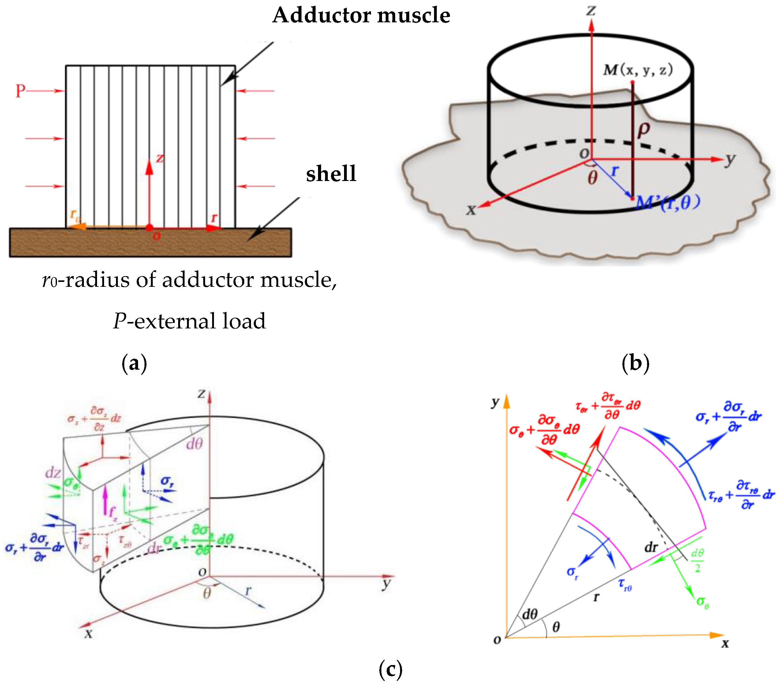
Figure 1. A simplified model of the scallop and the stress analysis diagram of the adductor muscle in cylindrical coordinates. (a) Simplified plane model of a scallop. (b) Simplified stereo model and cylindrical coordinate system of a scallop. (c) A sketch of the force analysis of the closure muscle in the cylindrical coordinate system.
Coatings 12 00963 g001
Figure 2. The detailed geometry parameters of the scallop shell.
Coatings 12 00963 g002
Figure 3. The stress distribution nephogram of the interface between the scallop closure muscle and shell in vertical plane bonding. (a) Mesh generation of scallop closure muscle in vertical plane contact with the shell. (b) Stress distribution nephogram. (I) Radial stress. (II) Circumferential stress. (III) Axial stress. (IV) Shear stress.
Coatings 12 00963 g003
Figure 4. A Mises stress distribution nephogram of the interface between the scallop closure muscle and shell at an angle in plane. (a) Simplified model of the scallop closure muscle in angular contact with the shell. (b) The Mises stress distribution nephogram of the interface. (I) α = 90°. (II) α = 80°. (III) α = 70°. (IV) α = 60°.
Coatings 12 00963 g004
Figure 5. The simplified meshing of the scallop closure muscle and shell in a non-planar combination. (A) Simplified model of non-planar contact. (B) Mesh generation of simplified non-planar contact model. The simplified model of non-planar contact between the scallop closure muscle and shell.
Coatings 12 00963 g005
Figure 6. The Mises stress distribution nephogram of the interface location between the shell and closure muscle under different periods and amplitude conditions. (a) T = 2π/10 A = 2 mm. (b) T = 2π/10 A = 5 mm. (c) T = 2π/50 A = 2 mm.
Coatings 12 00963 g006
Figure 7. The simplified mechanical model and stress distribution cloud diagram of non-ideal organic–inorganic interface of the scallop. (a) The simplified scallop model and mesh generation. (I) The simplified model of scallop structure. (II) Meshing of the scallop simplified model; (b) The stress distribution nephogram of the angle between the scallop closure muscle and shell. (I) α = 90°. (II) α = 80°. (III) α = 70°. (IV) α = 60°; (c) The stress distribution nephogram at different interface positions.
Coatings 12 00963 g007
Table 1. Mechanical parameters of scallop closure muscles and shells.
Mechanical ParametersAdductor MuscleShells
Young’s modulus/MPa2565,000
Poisson’s ratio0.450.25
Publisher’s Note: MDPI stays neutral with regard to jurisdictional claims in published maps and institutional affiliations.