
Effect of Surface Pre-Treatment on the Adhesion between HiPIMS Thick Cu:CuCNx Coating and WC-Co Shim

Department of Production Engineering, Manufacturing and Metrology Systems, KTH Royal Institute of Technology, Brinellvägen 68, 114 28 Stockholm, Sweden
*
Author to whom correspondence should be addressed.
Coatings 2022, 12(10), 1484; https://doi.org/10.3390/coatings12101484
Submission received: 18 September 2022
/
Revised: 1 October 2022
/
Accepted: 4 October 2022
/
Published: 6 October 2022
(This article belongs to the Topic Materials and Surface Treatment Processes Used for Engineering Applications)
Abstract
:High-power impulse magnetron-sputtering thick metal/carbon–nitride-doped metal-matrix multilayer nano-composite coating can be applied to cutting-tool holder components to improve cutting insert’s life. One of the challenges of such an add-on solution is the poor adhesion between the thick coating and the hard alloy substrate, such as WC-Co shim. This work presents a study on WC-Co substrate surface preparation methods for HiPIMS coating and its adhesion improvement. Three mechanical surface pretreatment methods were investigated: machining (grinding), diamond polishing, and grit blasting. White-light interferometry was used for substrate surface texture measurement before and after pretreatment. It was demonstrated that, compared to machining and diamond polishing, grit blasting can significantly improve the interface adhesion between the ~200 µm-thick Cu:CuCNx coating and WC-Co shim. Grit blasting was also found to be beneficial for improving the cutting insert’s life in the external turning process. In turning tests, the coating lifetime for grit-blasted shim was more than 90 min, whereas the coating lifetimes for machined shim (conventional shim) and diamond-polished shim were ~85 min and ~70 min, respectively. Further, by comparing the HiPIMS gradient chromium pre-layer between the coating and substrate for the different shims, the study also explained that the quasi-isotropic surface texture of grit-blasted shim is more advantageous for coating–substrate interface adhesion.
1. Introduction
Cutting tool components with high dynamic stiffness, thermal resistance, and high vibration damping capacity are in great demand for most subtractive machining operations. Cutting tool vibration is detrimental to the surface finish quality of machined parts and cutting insert life. For high-precision machining, a vibration-dampening mechanism close to the source of the vibration, i.e., at the cutting zone, not only increases cutting tool life but can also improve productivity and increase quality [1]. Magnetron-sputtered carbon–nitride coating (CNx) exhibiting high elasticity and adequate hardness can potentially be used for improving cutting tool dynamic stiffness [2] and for reducing the friction coefficient of higher load-capacity bearings [3]. Metal and metal-matrix carbon–nitride multilayered nanocomposite coating can improve milling tools’ cutting stability limit [4] and suppress chatter in the turning process [5]. The most fundamental prerequisite of such applications of nanocomposite coating is to ensure the required adhesion between substrate and coating to reduce mechanical wear [6] and improve the coated part’s life [7]. In order to suppress the high-frequency micro-vibration in metal cutting, e.g., external turning operations, an approximately 200 µm-thick pure copper (Cu) and carbon–nitride (CNx)-doped copper matrix multilayered nano-composite coating (denoted as Cu:CuCNx), synthesized by high-power impulse magnetron sputtering (HiPIMS), was applied in close proximity to the cutting tool inserts’ edge [1]. The coating was deposited on the cemented carbide (WC-Co) shims and placed under the cutting inserts. However, one of the great challenges of developing such high-frequency vibration damping mechanisms is the poor adhesion of such a thick coating to the WC-Co shims. Due to the high compressive residual stresses of the growing thick carbon-based coating [8] deposited by physical vapor deposition (PVD) and the thermal expansion coefficient mismatch between the substrate and the coating [9], the adhesion of carbon-based coatings onto WC-Co substrates is very poor.
Factors such as interface chemistry [10], roughness and elemental composition of substrate topography [11], degree of intermixing [8], and surface contamination layer [12] significantly influence the interfacial adhesion strength between the coating and substrate. High-performance interfacial adhesion between the coatings and metal substrates mainly takes place due to secondary bonding (hydrogen bonds and weak van der Waals force) at the interface, rather than primary bonding (covalent and ionic bonds), which is less likely to occur. Adhesion of a carbon-based coating to hard alloy substrates generally depends on mechanical bonding between the coating and the irregularities on the surface of the substrate. Strong mechanical bonding can be achieved by making the substrate surface rough enough to facilitate ‘interlocking’ between the coating and substrate and by increasing the substrate surface area via a roughening process that can enhance chemical interactions between the coating and substrate surface. Chemical interactions of the coating at the substrate surface (e.g., at the interface) is mostly influenced by surface energy (energy required to form a unit area of surface) of the substrate, which can be positively improved by abrasive mechanical pretreatment [13] and high-energy metallic ion bombardment [14] of the substrate surface. Such high-energy ion bombardment creates high-density active dangling bonds on the substrate surface and increases surface activation energy [15]. However, it is very important that the coating fill up the whole area of the substrate surface in valleys and pores to reduce the contact area gap between the coating and the substrate.
Broitman et al. [16] reported improved adhesion between a 3 µm-thick carbon–nitride (CNx) and SKF3 (AISI 52100) bearing stainless steel substrates by dual HiPIMS metal (Cr) ion plasma etching. The coating was deposited in an industrial chamber by DC magnetron sputtering. Other research has been carried out to improve the adhesion of thick (1 µm) C-based coating (DLC coating) on steel substrates [17,18]. Various methods such as deposition of metal- or ceramic-based interface adhesive layers [19,20], modification of substrate surface roughness by sandblasting or grit blasting [21], and removal of loosely bound alloy components from the surface by chemical or ion etching [22] can be applied to prepare a hard alloy surface such as WC-Co substrate to increase the deposited coating adhesion strength to the substrates. Ion etching using Ar+ ions with energy of 1.5 to 3.5 keV have been applied to remove loosely bound nano-diamond particles from WC-Co substrate surfaces to improve the mechanical bonding between the diamond film and the WC-Co substrate [22]. As a result, a maximum 40 μm-thick diamond coating could be deposited onto the WC-Co substrate by chemical vapour deposition (CVD) with better adhesion after only 20 s of ion etching. Broitman and Hultman [15] used HiPIMS Cr+Ar plasma to conduct sputter pretreatment of AISI 52100 steel substrates and achieved HF1-quality adhesion between the CNx coating and the steel substrates. Prior to vacuum deposition of CNx coating, the substrates were pulse biased in a Cr-HiPIMS plasma environment to sputter-clean the substrate surface and to implant the Cr+ ions on the substrate surface. As a result, the shallow Cr implantation on the substrate surface, promoting the formation of a gradually adherent interface, ensures very strong CNx coating adhesion to the steel substrate. Santiago et al. [18] applied HiPIMS Cr+ ion etching pretreatment for enhanced adhesion of DLC hard coating on steel substrate. They argued that compared to Ar+ glow discharge plasma etching, HiPIMS Cr+ ion plasma etching is very effective at removing surface contamination and native oxide layers, as well as for forming a gradual interface layer that ensures optimal coating substrate contact and significantly improves interface adhesion. They also pointed out that HiPIMS Cr+ ion plasma etching improves the stress distribution and reduces the coating deformation under loading conditions. Gomez et al. [17] conducted experiments using HiPIMS positive pulses and plasma immersion pretreatment for improving adhesion of DLC coatings to steel substrates, and they explained that the optimum W, Ti, and Cr concentrations in the carbon matrix can form carbide nanoclusters that are effective enough to increase interface strength. Al, Cr, and W-HiPIMS pretreatments on AISI52100 steel surfaces were investigated to see the effect of high-density metal ion etching of steel substrates for increasing the adhesion of CNx coating to the substrates [7]. It was found that compared to Al, Cr and W exhibit higher electron affinities, which is beneficial for strengthening the interfacial chemical bonding. Therefore, coherent interfaces are created due to the higher metallic bonding of Cr and W to C and N. However, metallic interlayer formation does not significantly increase adhesion strength between the CNx coating and substrate because the gradual Cr and W interlayer provides better interface adhesion compared to the gradual Al interlayer. Rather, it was pointed out that coating adhesion quality is directly related to the cleanliness and roughness of the substrate surface [23].
Prior to magnetron-sputtering deposition of thick coating onto hard metal alloy substrates such as WC-Co shim, mechanical pretreatment is an essential step for substrate surface preparation to remove residual surface contaminants, oxide layers, and surface impurities and to roughen the surface in order to modify surface characteristics such as hardness and activation energy to facilitate the preferential growth of the coating layer for better adhesion. Since Co is more ductile than WC, removing the Co phase near the surface of the WC-Co substrate by micro-blasting [24] and plasma ion etching [25] can enhance substrate coating adhesion by introducing new smaller surface-roughness peaks and by reducing existing high surface-roughness peaks. The introduction of new smaller surface-roughness peaks by exposing WC grain edges increases the surface area, and as a result, mechanical anchoring/bonding between the coating and substrate is increased. The removal of existing high surface-roughness peaks facilitates homogeneous growth site density of the deposited coating onto the substrate. Therefore, the contact stiffness between the coating and the substrate increases, which further enhances coating adhesion to the substrate. An 800 nm hydroxyapatite coating was deposited on sandblasted titanium implant by RF magnetron sputtering [26], and morphology analysis of the sandblasted Ti substrate revealed that the homogeneously deformed texture induced by sandblasting pretreatment was beneficial for achieving the desired coating adhesion to the substrate. Sandblasting and acid etching pretreatments of WC-Co substrate surface have been adopted [21] to improve the adhesion of diamond coating to the substrate by creating adequate mechanical interlocking between the diamond film and the roughened WC-Co substrate surface and by sufficiently increasing nucleation density of the diamond film. Als and Sohi [27] investigated the effect of grit (Al2O3 particles)-blasting parameters for increasing adhesion between 200 μm 80% ZrO2 –20% Y2O3 plasma spray coating and AISI 4130 steel substrates. They found that for the same blasting time and air pressure, a 90° blasting angle gives slightly higher arithmetic mean surface roughness but a significantly higher amount of grit residue in comparison with the results obtained for a blasting angle of 45°. Therefore, they concluded that the 45° blasting angle provides better adhesive strength between the thick coating and substrate. Griffiths et al. [28] prepared 250 µm alumina coating on a plain carbon steel plate, and to increase coating adhesion, the steel plate was blasted with 0.85 mm alumina grit at 90° with a substrate-to-nozzle distance of 100 mm. It was found that coating adhesion increases with increasing roughness, and the first layer of the coating preferentially builds up in the valleys of the grit-blasted surface. A previous study revealed [24] that, compared to polishing pretreatment, micro-blasting pretreatment of WC-Co substrate (cutting inserts) at high pressure can enhance coating adhesion and increase the machining performance of cutting inserts. Deuerler et al. [25] investigated different pretreatments of WC-Co cutting insert substrates and found that the combined techniques of chemical etching with Murakami’s solution, mechanical pretreatment by micro-scratching with diamond particles (EMU), and an amorphous carbon film (ACU) as intermediate layer provide better adhesion between the DLC film and WC-Co cutting insert.
The aim of this study is to investigate the effect of substrate surface texture, induced by metallographic surface treatment, on the interfacial adhesion between the thick Cu:CuCNx coating (thickness ~200 µm) and cemented carbide (WC-Co) shims. In this study, three different shim (substrate) surfaces were analysed: machined (received from vendor; denoted as ‘machined shims’), diamond-polished (denoted as ‘diamond-polished shims’), and grit-blasted (denoted as ‘grit-blasted shims’). A dual-cathode HiPIMS deposition system with synchronized pulsed bias was adopted to synthesize the thick Cu:CuCNx coating on the shims. The surface textures of the shims were measured and analysed using a Mirau interferometer and MountainsMap® surface metrology software. The surface topography of the different shims and the morphology of the synthesized coating were assessed by scanning electron microscopy (SEM) and with a built-in EDS system. Continuous external turning tests were conducted to demonstrate and quantitatively assess the adhesion of the coating on the shims. Prior to the machining test, a qualitative ‘heating–cooling’ test was adopted to realize the adhesion of the coating for three different shim surfaces. A strong correlation between the homogeneity of the surface texture, elemental composition, and interface adhesion was found. Four samples of each type (i.e., M, GB, and DP) were prepared. From each type, one sample was used for surface texture measurement, one sample was used for SEM-EDS after Cr-HiPIMS etching to investigate gradient Cr pre-layer formation, one sample was used for a qualitative ‘heating–cooling’ test, and one sample was used for the turning test. Due to the time-consuming experimental procedures (from the surface treatment of the shims to the machining tests of the coated shims took approximately 30 days), each experiment was conducted only once.
2. Experimental Details
2.1. Substrate Surface Preparation
WC-6 wt.% Co shims (11.5 mm × 11.5 mm × 3.5 mm) were adopted as substrates. Conventionally, shims (Figure 1a) are used as the ‘seats’ for indexable cutting tools and are placed between the cutting inserts and the tool holder (Figure 1b) to protect the tool holder in the event of cutting insert breakage. Shims are traditionally made from the same material as cutting inserts. Three different shim samples were prepared: (i) machined (M), or, as-received; (ii) diamond-polished (DP); and (iii) grit-blasted (GB).
Machined shims were directly collected from the commercial vendor (Palbit S.A., Albergaria-a-Velha, Portugal); per our request, the conventional shims (CS 120200) were ground at the vendor’s site to reduce thickness by 200 µm to accommodate the 200 µm surface coating.
Prior to any mechanical pretreatment, a strict cleaning procedure was adopted for all the substrates (shims) to ensure adequate bonding of the Cu:CuCNx coating to the substrate by removing contamination from and degreasing the substrate surfaces. The followed was the cleaning procedure: (i) scrubbing and cleaning the substrate surfaces with liquid soap and distilled water for 5 min; (ii) hot air drying; (iii) subsequent ultrasonic cleaning with isopropanol and acetone for 30 min each; and (iv) hot air drying.
Diamond polishing of the shims was conducted in two successive steps, first with 6 μm diamond suspension particles for 20 min and then with 3 μm diamond suspension particles for 20 min. As for the lubricant, isopropanol was mixed with glycine and water. For diamond polishing, the amount of diamond abrasive paste was selected based on the polishing cloth’s surface condition and the hardness of the WC-Co shims. Almost all the deformation and scratches from the surfaces of machined shims (conventional shims) were removed by successive diamond polishing with 6 μm and 3 µm diamond suspension particles.
Grit-blasting pretreatment of WC-Co shims was conducted in an air grit-blasting machine (Guyson Breadblaster, Stockholm, Sweden). Glass beads of 0.3 to 0.4 mm grit size distribution were chosen as blasting media. The glass beads were carried by compressed air in pipelines and impacted the samples through a nozzle. Samples were fixed perpendicular to the nozzle by a clamp. The scattering angle of the nozzle was about 6°, which meant most of the glass beads impacted the substrate perpendicularly. The compressed air pressure was adjusted to be 0.4 to 0.5 MPa, and nozzle–substrate distance was fixed at 100 mm. For each sample, grit blasting was performed for 5 min.
An optical microscope (Nikon Optiphot 150, Tokyo, Japan) equipped with a DeltaPix microscope camera (DeltaPix Invenio III, Smorum, Denmark) was used to capture surface topography images of the pretreated shims. The surface topography of the three kinds of shims can be observed in Figure 2.
2.2. Deposition of Thick Cu:CuCNx Multilayer Coating
Plasma ion pretreatment and Cu:CuCNx multilayered nanocomposite coating deposition were conducted in a double-cathode HiPIMS deposition system coupled with plasma-enhanced chemical vapor (PECVD) integrated into a Pfeiffer vacuum chamber of 0.3 m3 and equipped with three HiPIMS power source systems (IMPULSE™ 2-2, Starfire, Champaign, IL, USA) powered by three DC power supply (PD500X, KJLC, Jefferson Hills, PA, USA). Two of the HiPIMS units were connected to two cathodes, and one unit was connected to a substrate holder in a so-called ‘driver–follower’ configuration. Figure 3 shows a schematic representation of the HiPIMS system used in this work. One cathode was equipped with a rectangular Cu target (99.99% pure), and another one was equipped with a rectangular Cr (99.99% pure) target. Each of the target plates has an area of 27.5 × 10 cm2. The distance between the cathodes and the substrate holder was maintained at 10 cm, and all three substrate samples (DP, GB, and M shims) were mounted on the substrate holder on the same batch in order to avoid deposition condition differences in coating on the nominal, diamond-polished, and grit-blasted shims. The substrate holder was rotated at 2 rpm during the whole deposition process, except for the Ar+ plasma etching process, so that homogeneous coating with lower internal residual stress was deposited onto the shims. Prior to deposition and ion etching, the vacuum chamber was pumped down to a base pressure of 0.01 Pa by a turbo molecular pump and a dual-stage rotary vane pump. The plasma ion etching and the coating deposition sequence used in this work can be briefly described by the following:
High-pressure Ar+ ion plasma etching: To effectively eliminate the oxide layer and other contaminants from the substrate surfaces [16], Ar+ plasma etching of the substrates was conducted by creating a discharge at the substrate holder position powered by a medium-frequency AC power supply (HV-AC-350K, Foton, Nova Paka, Czech Republic) capable of delivering 1200 V at 350 kHz. The etching process was performed for 3 h using −700 V bias voltage at a frequency of 350 kHz. The Ar gas flowrate was set to 35 sccm and the process pressure was set at 11 Pa by reducing the pumping speed of the turbo molecular pump.
HiPIMS-Cr+ ion plasma etching: For chromium ion plasma etching of the substrate surface, Cr target was operated in HiPIMS mode with a peak power density of 0.3 kW/cm2, pulse duration of 50 µs, and pulse repetition frequency of 250 Hz. The Cr target plate was sputtered in an Ar gas environment with a flowrate of 14 sccm, and process pressure was 0.44 Pa. A negative bias voltage of −850 V with 350 kHz medium frequency was applied to the substrates. This process condition ensured highly dense ion flux of sputtered Cr at the substrate position, which was beneficial for not only profoundly eliminating substrate surface contamination, but also for producing low-energy implantation of energetic ions onto the substrate surfaces, which formed a graded interface between the substrate and the coating [16]. Cr+ ion plasma etching was conducted for 2 h.
Deposition of Cr pre-layer: To further increase the adhesion between the coating and the substrate, a thin interface-bonding layer of chromium was deposited by HiPIMS sputtering of the Cr target in an inert Ar gas environment with the following parameters: peak discharge power density of 0.3 kW/cm2, peak discharge current density of jCr = 0.61 A/cm2, discharge pulse length of 100 µs, discharge pulse frequency of 100 Hz, QAr = 14 sccm, and process pressure of 0.43 Pa. A synchronized pulse bias voltage of −100 V was applied to the substrate with the same main discharge pulse frequency. Bias pulse length was the same as discharge pulse length. Cr pre-layer deposition was conducted for 30 min.
Deposition of first CuCNx layer: HiPIMS of a Cu target was operated in a reactive nitrogen (N2) and acetylene (C2H2) gas environment mixed with argon (Ar) gas. The process parameters were as follows: peak discharge power density of 0.46 kW/cm2, peak discharge current density of jCu = 0.61 A/cm2, discharge pulse length of 70 µs, discharge pulse frequency of 170 Hz, QAr = 14 sccm, QN2 = 10 sccm, QC2H2 = 10 sccm, process pressure of 0.71 Pa, synchronized pulse bias voltage of −60 V with the same discharge pulse frequency and length without any delay. The first CuCNx layer deposition time was 41 h.
Deposition of Cu interlayer: a Cu interlayer was deposited in HiPIMS mode with a peak discharge power density of 0.4 kW/cm2, peak discharge current density of jCu =0.61 A/cm2, discharge pulse length of 70 µs, discharge pulse frequency of 200 Hz, QAr= 14 sccm, process pressure of 0.45 Pa, and synchronized pulse bias voltage of −60 V with the same discharge pulse frequency and length without any delay. Cu interlayer deposition was carried out for 10 h.
Deposition of second CuCNx layer: The second layer of CuCNx coating was deposited following the same procedure used for the deposition of the first CuCNx layer, except the peak discharge power density for this step was 0.41 kW/cm2. Deposition time for this step was 45 h.
2.3. Cu:CuCNx Coating Morphology Analysis
Topography of the Cu:CuCNx nano-composite coating, conventional shims (machined), and different pretreated (diamond-polished, grit-blasted, and Cr+ ion-etched) shims, as well as cross-sectional microstructure of the coating, were analysed using a Phenom Desktop scanning electron microscope (Phenom ProX SEM, ThermoFisher, Waltham, MA, USA) equipped with a CeB6 electron source in BSD (backscattered electron detector) mode with 15 kV acceleration voltage. For cross-section imaging, coated small steel disc samples were mounted in an epoxy resin followed by mechanical polishing (from coarser sandpapers to final polishing with diamond and silica nanoparticles). Elemental compositions of different layers of Cu:CuCNx coating and all the shim surfaces were analysed by in situ energy-dispersive X-ray spectroscopy (EDS, Thermo Scientific ChemiSEM Technology, ThermoFisher, Waltham, MA, USA) equipped with a thermoelectrically cooled silicon drift detector (SDD), ultra-thin silicon nitride (Si3N4) X-ray window, and ‘Element Identification’ (EID) software package. For topography, elemental composition ‘area mapping’ was used to scan an 850 to 900 µm2 area from four corners of the shims. Cross-sectional elemental composition was obtained by collecting X-rays from three different areas of each different layer of the coating.
2.4. Surface Texture Measurement
For each shim surface, a 219 μm × 219 μm area was measured in four locations (every corner) using a Mirau interferometer. No instrument-based filtering was used, nor was any surface pre-processing performed. Evaluation of the measured surface texture (for shims: M, DP, and GB) was done in two major steps:
Step 1: Surface processing
- Levelling and least-squares form-fitting using an LS-plane by subtraction;
- Filtering using a Robust Gaussian filter according to ISO 16610-31 [29], using cut-off (nesting index) = 0.08 mm with managing end effect.
Step 2: Surface qualitative analysis and visualization
- Surface isotropy and peak-height distribution;
- Surface roughness (S-L surface) as areal surface texture analyses according to ISO 25178 [30]—height parameter evaluation;
- Functional parameter analysis (Sk-group);
- Graphic visualization.
A white-light interferometer (Zygo NewView 7300 with a 50× magnification objective and an in-built Mirau interferometer, Middlefield, CT, USA) was used for surface-texture measurement. The parameters of the lens are presented in Table 1. No stitching was used in the measurement process. This was to eliminate lateral movement error replication and possible software-induced stitching error from the measurement.
A robust Gaussian regression filter (RGRF) was chosen to perform bandwidth filtering, as this filter includes compensation for filtered profile distortion at the end of the profile, unlike standard Gaussian filtering. All surfaces underwent the following processing:
Measured surfaces were analysed in the surface metrology software MountainsMap® Imaging Topography 7.4.9391.
2.5. Qualitative Adhesion Assessment of the Coating
To determine the sufficiency of coating adhesiveness, a simple and quick qualitative test was performed: the so-called ‘heating–cooling test’. The Cu:CuCNx-coated DP, GB, and M shims were placed in an oven and heated to ~300 °C for 1 h. After one hour, when the surface temperature of all the coated samples reached ~275 ± 15 °C, the samples were brought out of the oven and placed in an enclosed area with normal airflow so that the surface temperature of the samples could reach room temperature gradually. These heating and cooling conditions were chosen in order to avoid any phase transformation either in the Cu:CuCNx coating or in the WC-Co shim. Due to the different coefficients of thermal expansion of the WC-Co shim and the different layers of the coating material (e.g., Cu, CuCNx, and Cr), thermal residual stress accumulated between the different layers of the coating and in the interface between the coating and shim. Therefore, imperfect interfacial adhesion and cohesion were qualitatively assessed by observing coating peeling from the substrate (indication of sufficient adhesion) or flaking of coating layers (indication of lack of sufficient cohesion).
2.6. Machining Test
Continuous longitudinal external turning was adopted to investigate the Cu:CuCNx coating adhesion to the M, DP, and GB WC-Co shims. For each kind of coated shim, turning was conducted in an SMT-Swedturn-ST300 CNC machine with coolant (Figure 4). In the cutting-insert–coated-shim–cutting-tool-holder arrangement, the Cu:CuCNx coating was placed between the shim and the cutting insert. For each turning test, the recommended 6 N-m torque was applied to secure the insert with the shim in the tool holder.
The workpiece material was SS2541-03 alloy steel (34CrNiMoS6) with a diameter and length of 122 mm and 550 mm, respectively, and a hardness of 325 HB. Each turning test was conducted until the coating was delaminated (either adhesive or cohesive failure) from the shim, and the coating condition was visually inspected every 5 min. For each test, a new cutting edge was used until the insert’s flank wear reached 300 µm. Every 5 min, flank wear was measured using an optical microscope (Nikon Optiphot 150, Japan). For each test, a MIRCONA cutting insert (MIRCONA SNMG 120408-NM7) with a nose radius of 0.8 mm and rake angle of 75° in a Palbit tool holder (PSBN R 2525 M12) was used. The cutting parameters were selected as cutting speed Vc = 220 m/min, feed rate f = 0.35 mm/rev, and depth of cut ap = 1.2 mm.
3. Results
3.1. Surface Evaluation of the Different Pre-Treated Shims
3.1.1. Surface Texture Assessment
The three shim types have different surface textures due to their surface treatments. M was conventional machined, DP was diamond-polished, and GB was grit-blasted. Surface-texture character can be identified by isotropy (Table 2. Row A) and peak-height distribution (Table 2. Row B). It can be observed that the GB surface has a quasi-isotropic character (92.8%), while the M surface has an anisotropic character (3.19%). The DP surface has a quasi-anisotropic character (27.9%), as the polishing process leaves some scratches and marks due to abrasive diamond grains. The peak-height distribution (Table 3. Row B) indicates deviations in the surface-texture heights from the normal distribution.
One can see that only the GB shim has a close to normal distribution of peak and valley heights. This can be also confirmed by parametric analysis of the GB surface presented in Table 3, where the GB shim has parameters Ssk = −0.06 ± 0.04 and Sku = 3.35 ± 0.02. Commonly used height parameters such as Sa or Sq do not give much valuable information about the surface, as they can only indicate whether overall surface roughness is low or high. Therefore, we chose to use Ssk (skewness) and Sku (kurtosis) for surface pre-evaluation. Ssk concerns peak-height distribution. If Ssk = 0, then the peak-heights have normal distribution. For Ssk > 0, the surface has sharp peaks and flat valleys, while for Ssk < 0, the surface has plateau-like peaks with sharp valleys. Sku relates to the tip geometry of peaks and valleys. If Sku = 3, then the peak-height distribution is normal, which means the shape of the tips of peaks and valleys is similar. For Sku > 3, the tips of peaks and valleys are sharper, but for Sku < 3, the surface peaks and valleys are duller.
It is worth mentioning that the Sz for the M and GB surfaces has similar values, despite their differences in surface textures (Table 4, Row A-C). This proves that height parameters are not enough to assess the surface. Hence, further surface analyses focused on the functional parameters from the Sk group. It can be said that the GB surface has almost equally distributed peaks and valleys in the z-axis (Table 4, Row D). The DP surface has significantly lower surface texture height in comparison to the conventional (around 12 times lower) and grit-blasted surfaces (around 25 times lower). From Table 4, Row D, it can be also concluded that grit blasting equalizes surface texture by bringing balance between peak (represented by Spk) and valley (represented by Svk) heights.
3.1.2. Surface Topography
Unidirectional machining (grinding) of the conventional M shim (unidirectional machining mark is visible in Figure 2a and the figure in Table 4, Row A, M shim) induced compressive residual stress at the boundary layer of the machining marks due to superficial plastic deformation [31]. The circular motion of the undefined diamond particles induced local plastic deformation at the surface structure of the diamond-polished shim, due to which local tensile hoop stress accumulated as residual stress [32]. This residual stress can cause intense damage and create micro-cracks to the surface structure of the DP shim (see Figure 2b). The surface topography of the grit-blasted shim can be observed in Figure 2c and the figure in Table 4, Row A, GB shim. High-pressure glass bead (grit) bombardment of the shim surface induces high compressive residual stress at the upper surface region of the shim [21,33]. The quasi-homogeneous surface roughness of the GB shim (see Table 2. GB shim) and the approximately normal distribution of the shapes of peaks and valleys (see Table 4. Row-D) make the local plastic deformation and residual stress uniform.
From the EDS elemental composition of M, DP, and GB shims, shown in Table 5, it can be realized that, compared to diamond polishing, grit blasting pretreatment significantly reduced WC and Co phases from the shim’s upper surface region. Compared to conventional M shim, in GB shim, the mass percentage concentrations of W and Co were reduced by ~2.5% and ~9.4%, respectively, whereas for DP shim, only W reduction (~1.9%) was observed. For DP shim, no significant change in Co content was detected in EDS analysis. The same trend can also be observed for Cr+ ion-etched GB shim and DP shim (see Table 5). The WC phase reduction in GB shim can be attributed to the creation of new normally distributed peaks and valleys by breaking the sharper WC grain peaks of the conventional M shim, which is in agreement with [24]. In the case of Co phase reduction in GB shim, it can be postulated that grit blasting increases the nucleation density of adatoms, molecules, and ions of the growing coating material by shattering and sputtering away Co phases from WC-Co structures located at the outermost layer of the shim’s surface [21].
3.2. Cu:CuCNx Coating Morphology
The SEM microstructure and EDS analyses of the coating material (see Figure 5 and Figure 6a) confirm three distinct phases: Cr (pre-layer), CNx mixed Cu matrix (CuCNx), and Cu layers. SEM cross-section images (Figure 5) shows the densely packed columnar microstructure in both of the composite CuCNx layers. Due to high current-density (0.61 A/cm2) and reduced plateau discharge (pulse frequency 170 Hz and pulse length 70 µs), the high ion flux density at the substrate position facilitates growth of the densely packed microstructure [34,35]. The structure can be characterized as amorphous since no structure such as particles, agglomerates, or porous clusters are observed from SEM micrographs [2]. No periodic nanostructure can be observed, which was clearly visible in [4,5]. The absence of periodic nanostructure in the composite CuCNx layer of the deposited coating material can be correlated to the lower average power density on the cathode and high substrate rotation speed comparing to the values reported in [4,5].
The total thickness of the coating, measured in an SEM cross-section image (Figure 5), was 192 ± 0.1 µm. EDS analysis confirmed that both CuCNx layers were enriched with Cu, C, N, and O with different compositions. Each layer’s approximate thickness and elemental composition are provided in Table 5. The presence of O in the samples can be due to the long exposure of coating material in the atmospheric environment after the deposition process.
The SEM cross-section of the Cr pre-layer in Cu:CuCNx coating (Figure 6a) and EDS elemental composition (Table 6. Cr pre-layer) proves that a gradual amorphous transition layer (mixture of Cr and CuCNx) forms between the coating and the substrate. It has been proven that this kind of gradient interface can improve the interfacial adhesion strength between the coating and substrate by reducing the incoherent shear stress distribution [3].
EDS elemental composition of Cr+ ion-etched WC-Co shim (see Figure 6b, Table 5, Cr+ ion-etched GB shim and Cr+ ion-etched DP shim) confirms shallow implantation of Cr layer on the WC-Co shim. During HiPIMS metal ion etching, two counteracting phenomena [15] take place at the substrate position: (i) from the highly ionized Cr-HiPIMS plasma, a large portion of Cr+ ion is attracted to the substrate position due to the application of high negative bias voltage (−850 V) at the 350 kHz medium frequency and high-energy Cr+ ion bombardment of the substrate surface, and (ii) condensation of the Cr+ ion and adatoms occurs at the substrate surface. The graded Cr interface formation is initiated by shallow implantation of highly energetic (several hundred eV) incoming Cr+ ions at the substrate surface due to the high electron affinity of the metal ion and incorporation into the WC-Co phase structure.
3.3. Qualitative Adhesion Assessment
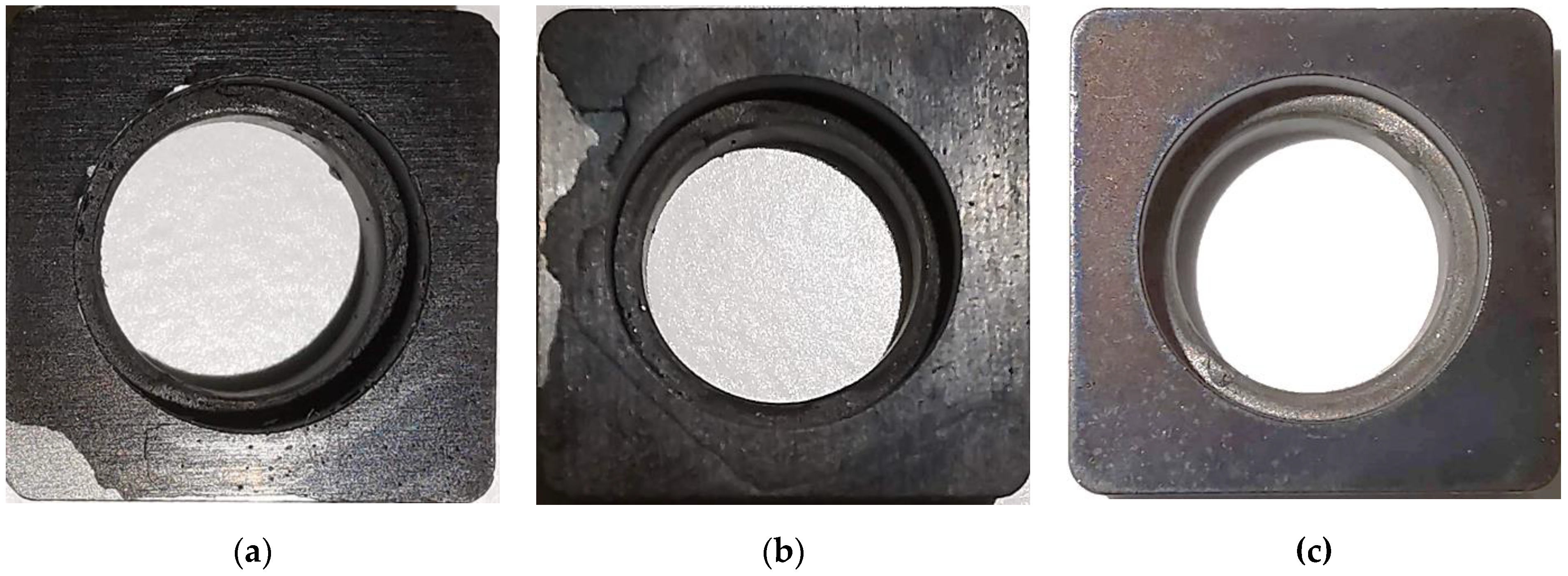
Figure 7 depicts the coating condition on the three types of shims after the qualitative ‘heating–cooling’ test. From the figure, it can be seen that the Cu:CuCNx coating is fractured and delaminated from the DP shim in area A and from the conventional M shim in area B. Furthermore, the coating of DP and M shims is oxidized (coating colour changed). Whereas for GB shim, a small portion of the coating is lost (area C). From the qualitative assessment, it is clearly visible that Cu:CuCNx coating adhesion to GB shim is comparatively better than that of M and DP shims.
PVD processes such as HiPIMS deposition are known to induce high compressive stress in the coating material, and this compressive stress increases with increasing coating thickness [16,35]. So it can be assumed that the HiPIMS-deposited thick (~200 µm) Cu:CuCNx has high compressive residual stress. During the heating cycle of the coated shim, due to the thermal expansion coefficient mismatch between the coating and shim material, a thermal residual stress is built up at the interface region [21]. During the cooling cycle, the high local tensile and compressive residual stresses in DP and M shim surfaces inhibit the relaxation of induced thermal residual stress at the interface between the coating and shim. As a result, the high compressive stress in the Cu:CuCNx coating facilitates ‘flaking’ or delamination of the coating from the substrate surfaces. On the other hand, the uniform compressive residual stress in the GB shim’s surface texture expedites thermal residual stress relaxation at the interface, and thus enhances the interfacial adhesion strength between the Cu:CuCNx coating and WC-Co shim.
3.4. Machining Test
To determine the influence of mechanical surface pretreatment on Cu:CuCNx coating adhesion to the WC-Co shim, a turning test was carried out. The description of the cutting condition, insert, tool holder, and workpiece material is provided in Section 2.6. For each type of coated shim, the influence of Cu:CuCNx coating adhesion on machining performance was evaluated based on cutting insert wear [36]. Results of the turning test with the machining parameters are summarized in Table 7. the machining performance of coated GB shim was better than that of coated M and coated DP shims.
Within the same cutting condition and using the same cutting parameters, the Cu:CuCNx coating in M and DP persisted for 85 and 70 min, respectively. In both cases, adhesive failure occurred, i.e., the coating delaminated from the shim surfaces (see Figure 8a,b). It can also be observed that (Figure 8) the delaminated coating area on DP shim was larger than that of the M shim. For the GB shim, after 90 min of turning, the Cu:CuCNx coating was still undamaged, and no micro- or macro-cracks were visible (see Figure 8c). Therefore, it can be postulated that the grit-blasting pretreatment creates uniform surface texture with sufficient roughness, which increases the mechanical bonding between the Cu:CuCNx coating and WC-Co shim surface. As a result, the interface adhesion strength between the coating and shim increases.
Every 5 min during the turning test, both insert flank wear and the shim’s coating condition were measured and visually examined, respectively; the last value of insert flank wear before coating breakage is reported in Table 7. After 65 min, insert flank wear for the coated DP shim was 259 µm, whereas after 80 min, the insert flank wear for the coated M and GB shims were 276 and 249 µm, respectively.
4. Discussion
4.1. Effect of the HiPIMS Cr Pre-Layer on the Adhesion between ~200 µm Cu:CuCNx Coating and WC-Co Shim
Broitman et al. [15,16], Gómez et al. [17], and Santiago et al. [18] demonstrated that high-energy Cr-HiPIMS plasma etching and HiPIMS deposition of Cr pre-layer increases the interfacial adhesion between carbon-based magnetron-sputtered coating and metal substrates. In this study the HiPIMS-deposited Cu:CuCNx coating thickness was 192 µm, which was almost 5 times higher than the reported values in the previous studies (max. 40 µm). Magnetron-sputtered coatings are known to have increased intrinsic compressive stress with increasing thickness. From SEM-EDS analysis in this study, it was observed that a 0.5 µm gradient Cr pre-layer and an intermixing interface (WC-Co:Cr:CuCNx) were present in all samples (coated M, DP, and GB shims). Additionally, the ‘heating–cooling’ and turning test results show that the Cr pre-layer and the intermixing interface do not create sufficient interfacial adhesion between the ~200 µm Cu:CuCNx coating and WC-Co shim. Rather it can be safely anticipated that the homogeneous (global) intrinsic compressive stress (compared to local compressive stress in M shim and local tensile stress in DP shim) in the near-surface of the GB shim is highly beneficial for modifying the initial layer of the coating for increasing interface adhesion [28]. This will be discussed further in Section 4.3.
4.2. Effect of the Surface Pretreatments on the Adhesion between ~200 µm Cu:CuCNx Coating and WC-Co Shim
Aggressive mechanical pretreatment such as grit blasting is known to significantly improve interface adhesion strength by removing inorganic surface contaminants and native oxide layers. High-pressure impinging grit particles during grit blasting shatter existing large WC grains of the WC-Co shim and sputter away the loosely bound fractured grains. As a result, the introduction of a large quantity of new, smaller WC grains makes the shim’s surface rougher. The high surface roughness generated by grit blasting, significantly increases the shim’s surface area for upcoming HiPIMS-deposited particles’ contact with the substrate. With increasing the deposited film’s species-to-substrate surface contact area, the interatomic and metallurgical interactions between the deposited film and the substrate surface increases, which enhances mechanical bonding [37].
Only the near-surface structure of the substrate influences the deposition of coating particles. Cobalt in the WC-Co phase in the near-surface structure of the shim can diffuse in the coating structure and make interface adhesion weak. The initial layer of the coating preferentially builds up in the valleys. Therefore, the removal of the Co phase via grit blasting can increase the contact stiffness between the Cr pre-layer of Cu:CuCNx coating and WC-Co shim substrate [24].
The skewness (Ssk) and kurtosis (Sku) of the GB shim surface (−0.06 and 3.35, respectively) indicate that the grit-blasted surface of the shim is quasi-isotropic, i.e., the height and shape distribution of the peaks and valleys in the surface are quasi-uniform. The same information can also be found from the core height (Sk), reduced peak height (Spk), and reduced valley height (Svk) of the GB shim (Sk, Spk, and Svk are 0.939 µm, 0.352 µm, and 0.396 µm, respectively). Whereas the surface characteristics (Ssk, Sku, Sk, Spk, Svk) of the conventionally machined (M) and diamond-polished (DP) shims indicate that M and DP shim surface textures are anisotropic and quasi-anisotropic, respectively (see Table 3). A quasi-isotropic surface texture along with numerous peaks, valleys, and flats can enhance the nucleation density for the preferential growth of the HiPIMS-deposited coating.
4.3. Effect of WC-Co Shim Surface Pretreatment on Machining Performance
During turning, the friction between the cutting tool and the workpiece excites a wide range of frequencies, ranging from hundreds of hertz (Hz) to several thousands of Hz [1]. The high-impact cutting force along with micro-vibration (vibrations with high frequency) generate cyclic fatigue stress continuously acting on the cutting edge of the inserts. At the tool–chip interface, the contact load is concentrated on a very small area and, as a result, very high normal and shear stresses, with maximum values of 900–1600 MPa and about 30%–60% of normal stress, respectively, act on the interface [38]. Therefore, the whole cutting tool arrangement, including the shim, experiences the same normal and shear stresses along the edge parallel to the insert’s cutting edge. It has been reported that maximum shear stress on the shims was 8-12.5 MPa [39]. From the external turning test conducted in this study, it was observed that, with the same thickness, the Cu:CuCNx-coated GB shim shows better machining performance compared to coated M and DP shims. The better machining performance of the coated GB shim in terms of higher coating life (more than 90 min) and minimal insert flank wear (249 µm after 80 min of turning) indicate that the quasi-homogeneous surface characteristics of the GB shim are beneficial for the preferential epitaxial growth of the HiPIMS coating.
The quasi-isotropic nature of the GB shim has homogeneous surface activation energy, which facilitates the diffusion of adatoms in all directions across the surface. As a result, the probability of nucleating adatom islands increases homogeneously, which promotes the growth of a dense columnar structure without nodular defects (voids, pits, and trenches created due to shadowing), and with low coating-surface roughness [40,41]. Whereas on M and DP shims, due to having unidirectional trenches or scratches and local pits in the surface texture, the activation energy for adatom diffusion is concentrated along surface texture defects (trenches and pits), which restricts adatom mobility and dense uniform columnar growth of the coating structure. Rather, it was found that the coating structure on anisotropic surface textures has a high concentration of nodular defects and voids, and has higher coating surface roughness [40]. Thus, the irregular contact area between the cutting inserts and coated shims (in the case of M and DP shims) caused by higher coating surface roughness accumulates concentrated normal and shear stresses, due to which delamination of the coating occurs. Since the number of local deformation sites was highest on the DP shim surface, its coating lifetime was the lowest. The preferential dense columnar structures of the thick Cu:CuCNx multilayered coating on GB shim also explain the better machining performance in terms of the lowest insert wear because of the higher material damping loss [2,5].
If the substrate surfaces have non-uniform local deformation sites (such as in DP surfaces) or local scratches (such as in M surfaces) during the initial stage of coating growth, the thermal diffusion of adatoms is restricted in deformation sites and scratches [40]. As a result, high thermal residual stress accumulates in the first layer of coating. For the same reason, the metal (Cr) ions and neutrals, entrapped in the local deformation sites during the Cr-HiPIMS plasma etching and HiPIMS pre-layer deposition steps, build up high tensile stress in the Cr pre-layer. The high thermal and tensile residual stresses in the Cr pre-layer are detrimental to coating adhesion, which was noticed in ‘heating–cooling’ and turning tests for Cu:CuCNx-coated M and DP shims. On the other hand, the quasi-isotropic surface texture of the GB shim, along with higher surface roughness, minimized the accumulation of thermal and tensile residual stress in the pre-layer.
5. Conclusions
In this study, a ~200 µm-thick Cu:CuCNx multilayered nanocomposite coating was deposited on WC-Co shims by a double-cathode HiPIMS deposition system. Three different kinds of surface textures, generated by the three types of mechanical pretreatment processes—grinding (as-received conventional shim), diamond polishing, and grit blasting—were studied to investigate the effect of surface texture on the interface adhesion between the coating and the substrates. A qualitative ‘heating–cooling’ test and turning test were adopted to demonstrate the influence of WC-Co shim surface characteristics on interface adhesion and machining performance. The following findings were observed:
- ▪
- Grit blasting increases the surface roughness by introducing new, smaller WC grains by shattering the existing sharper WC grains.
- ▪
- Grit blasting can significantly remove loosely bound Co binder from the WC-Co structure.
- ▪
- The GB surface has a quasi-isotropic character (92.8%), while the M surface has an anisotropic character (3.19%). The DP surface has a quasi-anisotropic character (27.9%)
- ▪
- High-density Cr+ HiPIMS plasma etching can create an intermixing interface (WC-Co:Cr:CuCNx) by implementing chromium ions and neutrals in the near-surface structure of the shims.
- ▪
- The CNx-doped copper matrix with pure copper interlayer (Cu:CuCNx) coating has higher dense columnar structure without any visible defects. The coating is amorphous in nature with a gradient Cr pre-layer of 0.5 µm.
- ▪
- Cu:CuCNx coating on GB shim has better interface adhesion strength than that on DP and conventional M shims.
- ▪
- Compared to M and DP coated shims, Cu:CuCNx coating on GB shim has the highest coating life and the lowest insert flank wear.
- ▪
- The following inferences were made:
- ▪
- In the present case of ~200 µm-thick Cu:CuCNx coating, only the 0.5 µm Cr pre-layer and the intermixing interface is not sufficient to create adequate interface adhesion between the coating and WC-Co shim.
- ▪
- The quasi-isotropic surface texture along with the high surface roughness of the GB shim is beneficial for increasing interface adhesion strength.
- ▪
- The homogeneous distribution of peaks and valleys of the GB shim is advantageous for the preferential growth of the dense columnar structure of the coating, due to which the cutting insert’s life increases (or flank wear decreases).
Author Contributions
Conceptualization, M.M.-U.R. and R.T.; methodology, R.T.; validation, M.M.-U.R., R.T. and A.A.; formal analysis, R.T.; investigation, M.M.-U.R.; resources, A.A.; data curation, M.M.-U.R. and R.T.; writing—original draft preparation, M.M.-U.R. and R.T.; writing—review and editing, R.T. and A.A.; visualization, M.M.-U.R.; supervision, R.T.; project administration, A.A.; funding acquisition, A.A. All authors have read and agreed to the published version of the manuscript.
Funding
This research was funded by Eurostars (project acronym HiCut), reference number 2017-03571; and DMMS (Design & Management of Manufacturing Systems), a Centre at the Production Engineering Department, KTH Royal Institute of Technology, Sweden.
Institutional Review Board Statement
Not applicable.
Informed Consent Statement
Not applicable.
Data Availability Statement
Not applicable.
Acknowledgments
The authors wish to thank Mihai Nicolescu for his valuable contributions in research discussion, and Plasmatrix Materials AB for providing the HiPIMS deposition equipment.
Conflicts of Interest
The authors declare no conflict of interest.
References
- Rashid, M.; Guo, S.; Adane, T.F.; Nicolescu, C.M. Advanced Multi-Functional Coatings for Vibration Control of Machining. J. Mach. Eng. 2020, 20, 5–23. [Google Scholar] [CrossRef]
- Rashid, M.U.; Archenti, A. Manufacturing and Characterization of a Carbon-Based Amorphous (a-CNX) Coating Material. Nanomanuf. Metrol. 2018, 1, 156–170. [Google Scholar] [CrossRef] [Green Version]
- Bakoglidis, K.D.; Nedelcu, I.; Schmidt, S.; Greczynski, G.; Ehret, P.; Hultman, L. Rolling contact fatigue of bearing components coated with carbon nitride thin films. Tribol. Int. 2016, 98, 100–107. [Google Scholar] [CrossRef]
- Fu, Q.; Lorite, G.S.; Rashid, M.M.U.; Neuhaus, R.; Cada, M.; Hubicka, Z.; Pitkänen, O.; Selkälä, T.; Uusitalo, J.; Glanz, C.; et al. High Dynamic Stiffness Mechanical Structures with Nanostructured Composite Coatings Deposited by High Power Impulse Magnetron Sputtering. Carbon 2016, 98, 24–33. [Google Scholar] [CrossRef]
- Fu, Q.; Lorite, G.S.; Rashid, M.M.-U.; Selkälä, T.; Uusitalo, J.; Toth, G.; Kordas, K.; Österlind, T.; Nicolescu, C.M. Suppressing Tool Chatter with Novel Multi-Layered Nanostructures of Carbon Based Composite Coatings. J. Mater. Process. Technol. 2015, 223, 292–298. [Google Scholar] [CrossRef]
- Lau, K.H.; Li, K.Y. Correlation between adhesion and wear behaviour of commercial carbon based coating. Tribol. Int. 2006, 39, 115–123. [Google Scholar] [CrossRef]
- Bakoglidis, K.D.; Schmidt, S.; Greczynski, G.; Hultman, L. Improved Adhesion of Carbon Nitride Coatings on Steel Substrates Using Metal HiPIMS Pretreatments. Surf. Coat. Technol. 2016, 302, 454–462. [Google Scholar] [CrossRef]
- Chen, C.C.; Hong, F.C.-N. Interfacial studies for improving the adhesion of diamondlike carbon films on steel. Appl. Surf. Sci. 2005, 243, 296–303. [Google Scholar] [CrossRef]
- Mallika, K.; Komanduri, R. Diamond coatings on cemented tungsten carbide tools by low-pressure microwave CVD. Wear 1999, 224, 245–266. [Google Scholar] [CrossRef]
- Jones, B.J.; Anguilano, L.; Ojeda, J.J. Argon plasma treatment techniques on steel and effects on diamond-like carbon structure and delamination. Diam. Relat. Mater. 2011, 20, 1030–1035. [Google Scholar] [CrossRef]
- Voevodin, A.A.; Capano, M.A.; Laube, S.J.P.; Donley, M.S.; Zabinski, J.S. Design of a Ti/TiC/DLC functionally gradient coating based on studies of structural transitions in Ti–C thin films. Thin Solid Films 1997, 298, 107–115. [Google Scholar] [CrossRef]
- Morshed, M.M.; McNamara, B.P.; Cameron, D.C.; Hashmi, M.S.J. Effect of surface treatment on the adhesion of DLC film on 316L stainless steel. Surf. Coat. Technol. 2003, 163–164, 541–545. [Google Scholar] [CrossRef]
- Weldon, D.G. Why coatings work. In Failure Analysis of Paints and Coatings, 1st ed.; John Wiley and Sons, Ltd.: Imperial, PA, USA, 2009; pp. 9–23. [Google Scholar]
- Cailler, M.; Lee, G.H. Scratch Adhesion Test of Magnetron-Sputtered Copper Coatings on Aluminium Substrates: Effects of the Surface Preparation. Thin Solid Films 1989, 168, 193–205. [Google Scholar] [CrossRef]
- Broitman, E.; Hultman, L. Adhesion Improvement of Carbon-Based Coatings through a High Ionization Deposition Technique. J. Phys. Conf. Ser. 2012, 370, 012009. [Google Scholar] [CrossRef] [Green Version]
- Broitman, E.; Czigány, Z.; Greczynski, G.; Böhlmark, J.; Cremer, R.; Hultman, L. Industrial-Scale Deposition of Highly Adherent CNx Films on Steel Substrates. Surf. Coat. Technol. 2010, 204, 3349–3357. [Google Scholar] [CrossRef] [Green Version]
- Gómez, I.; Claver, A.; Santiago, J.A.; Fernandez, I.; Palacio, J.F.; Diaz, C.; Mändl, S.; Garcia, J.A. Improved Adhesion of the DLC Coating Using HiPIMS with Positive Pulses and Plasma Immersion Pretreatment. Coatings 2021, 11, 1070. [Google Scholar] [CrossRef]
- Santiago, J.A.; Fernández-Martínez, I.; Wennberg, A.; Molina-Aldareguia, J.M.; Castillo-Rodríguez, M.; Rojas, T.C.; Sánchez-López, J.C.; González, M.U.; García-Martín, J.M.; Li, H.; et al. Adhesion Enhancement of DLC Hard Coatings by HiPIMS Metal Ion Etching Pretreatment. Surf. Coat. Technol. 2018, 349, 787–796. [Google Scholar] [CrossRef]
- Park, J.K.; Lee, H.J.; Lee, W.S.; Baik, Y.J. Effect of TiAl-based interlayer on the surface morphology and adhesion of nanocrystalline diamond film deposited on WC–Co substrate by hot filament CVD. Surf. Coat. Technol. 2014, 258, 108–113. [Google Scholar] [CrossRef]
- Poulon-Quitin, A.; Faure, C.; Teulé-Gay, L.; Manaud, J.P. A multilayer innovative solution to improve the adhesion of nanocrystalline diamond coatings. Appl. Surf. Sci. 2015, 331, 27–34. [Google Scholar] [CrossRef] [Green Version]
- Shen, X.; Wang, X.; Sun, F.; Ding, C. Sandblasting Pretreatment for Deposition of Diamond Films on WC-Co Hard Metal Substrates. Diam. Relat. Mater. 2017, 73, 7–14. [Google Scholar] [CrossRef]
- Linnik, S.A.; Gaydaychuk, A.V.; Okhotnikov, V.V. Improvement to the Adhesion of Polycrystalline Diamond Films on WC-Co Cemented Carbides through Ion Etching of Loosely Bound Growth Centers. Surf. Coat. Technol. 2018, 334, 227–232. [Google Scholar] [CrossRef]
- Mellali, M.; Grimaud, A.; Leger, A.C.; Fauchais, P.; Lu, J. Alumina Grit Blasting Parameters for Surface Preparation in the Plasma Spraying Operation. J. Therm. Spray Technol. 1997, 6, 217–227. [Google Scholar] [CrossRef]
- Bouzakis, K.-D.; Michailidis, N.; Hadjiyiannis, S.; Efstathiou, K.; Pavlidou, E.; Erkens, G.; Rambadt, S.; Wirth, I. Improvement of PVD Coated Inserts Cutting Performance, through Appropriate Mechanical Treatments of Substrate and Coating Surface. Surf. Coat. Technol. 2001, 146–147, 443–450. [Google Scholar] [CrossRef]
- Deuerler, F.; van den Berg, H.; Tabersky, R.; Freundlieb, A.; Pies, M.; Buck, V. Pretreatment of Substrate Surface for Improved Adhesion of Diamond Films on Hard Metal Cutting Tools. Diam. Relat. Mater. 1996, 5, 1478–1489. [Google Scholar] [CrossRef]
- Grubova, I.; Priamushko, T.; Surmeneva, M.; Korneva, O.; Epple, M.; Prymak, O.; Surmenev, R. Sand-Blasting Treatment as a Way to Improve the Adhesion Strength of Hydroxyapatite Coating on Titanium Implant. J. Phys. Conf. Ser. 2017, 830, 012109. [Google Scholar] [CrossRef] [Green Version]
- Asl, S.K.; Sohi, M.H. Effect of Grit-Blasting Parameters on the Surface Roughness and Adhesion Strength of Sprayed Coating. Surf. Interface Anal. 2010, 42, 551–554. [Google Scholar] [CrossRef]
- Griffiths, B.J.; Gawne, D.T.; Dong, G. The Role of Grit Blasting in the Production of High-Adhesion Plasma Sprayed Alumina Coatings. Proc. Inst. Mech. Eng. Part B J. Eng. Manuf. 1997, 211, 1–9. [Google Scholar] [CrossRef]
- ISO 16610-31; Geometrical Product Specifications (GPS)—Filtration—Part 31: Robust Profile Filters: Gaussian Regression Filters. ISO: Geneva, Switzerland, 2016.
- ISO 25178-2; Geometrical Product Specifications (GPS)—Surface Texture: Areal—Part 2: Terms, Definitions and Surface Texture Parameters. ISO: Geneva, Switzerland, 2012.
- Sprute, T.; Tillmann, W.; Grisales, D.; Selvadurai, U.; Fischer, G. Influence of Substrate Pre-Treatments on Residual Stresses and Tribo-Mechanical Properties of TiAlN-Based PVD Coatings. Surf. Coat. Technol. 2014, 260, 369–379. [Google Scholar] [CrossRef]
- Everaerts, J.; Salvati, E.; Korsunsky, A.M. Nanoscale Depth Profiling of Residual Stresses Due to Fine Surface Finishing. Adv. Mater. Interfaces 2019, 6, 1900947. [Google Scholar] [CrossRef]
- Staia, M.H.; Ramos, E.; Carrasquero, A.; Roman, A.; Lesage, J.; Chicot, D.; Mesmacque, G. Effect of Substrate Roughness Induced by Grit Blasting upon Adhesion of WC-17% Co Thermal Sprayed Coatings. Thin Solid Films 2000, 377–378, 657–664. [Google Scholar] [CrossRef]
- Gudmundsson, J.T.; Brenning, N.; Lundin, D.; Helmersson, U. High power impulse magnetron sputtering discharge. J. Vac. Sci. Technol. A Vac. Surf. Film 2012, 30, 30801. [Google Scholar] [CrossRef] [Green Version]
- Lundin, D.; Sarakinos, K. An introduction to thin film processing using high-power impulse magnetron sputtering. J. Mater. Res. 2012, 27, 780–792. [Google Scholar] [CrossRef] [Green Version]
- ISO 3685; Tool Life Testing in Single-Point Turning Tools, 2nd ed. ISO: Geneva, Switzerland, 1983.
- Varacalle, D.J.; Guillen, D.P.; Deason, D.M.; Rhodaberger, W.; Sampson, E. Effect of Grit-Blasting on Substrate Roughness and Coating Adhesion. J. Therm. Spray Technol. 2006, 15, 348–355. [Google Scholar] [CrossRef]
- Grzesik, W. Tribology of Metal Cutting. In Advanced Machining Processes of Metallic Materials, 2nd ed.; Elsevier: Amsterdam, The Netherlands, 2017; pp. 197–214. [Google Scholar]
- Rogov, V.A.; Ghorbani, S.; Popikov, A.N.; Polushin, N.I. Improvement of Cutting Tool Performance during Machining Process by Using Different Shim. Arch. Civ. Mech. Eng. 2017, 17, 694–710. [Google Scholar] [CrossRef]
- Lai, C.-C.; Boyd, R.; Svensson, P.-O.; Höglund, C.; Robinson, L.; Birch, J.; Hall-Wilton, R. Effect of Substrate Roughness and Material Selection on the Microstructure of Sputtering Deposited Boron Carbide Thin Films. Surf. Coat. Technol. 2022, 433, 128160. [Google Scholar] [CrossRef]
- Anders, A. A Structure Zone Diagram Including Plasma-Based Deposition and Ion Etching. Thin Solid Films 2010, 518, 4087–4090. [Google Scholar] [CrossRef]
Figure 1.
(a) Conventional shim and (b) shim placed between the cutting insert and the tool holder.
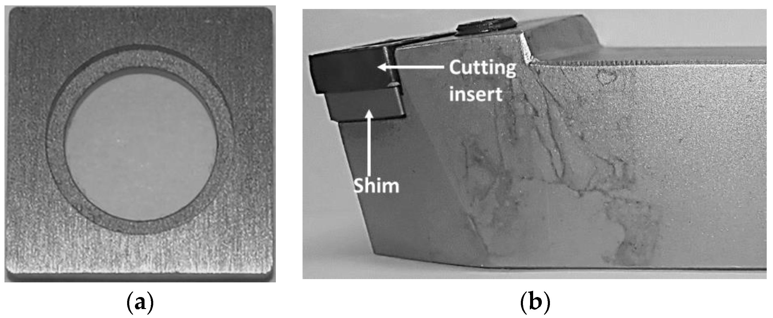
Figure 2.
Surface topography before coating process, observed through an optical microscope: (a) conventional machined shim; (b) diamond-polished shim; and (c) grit-blasted shim.
Figure 2.
Surface topography before coating process, observed through an optical microscope: (a) conventional machined shim; (b) diamond-polished shim; and (c) grit-blasted shim.
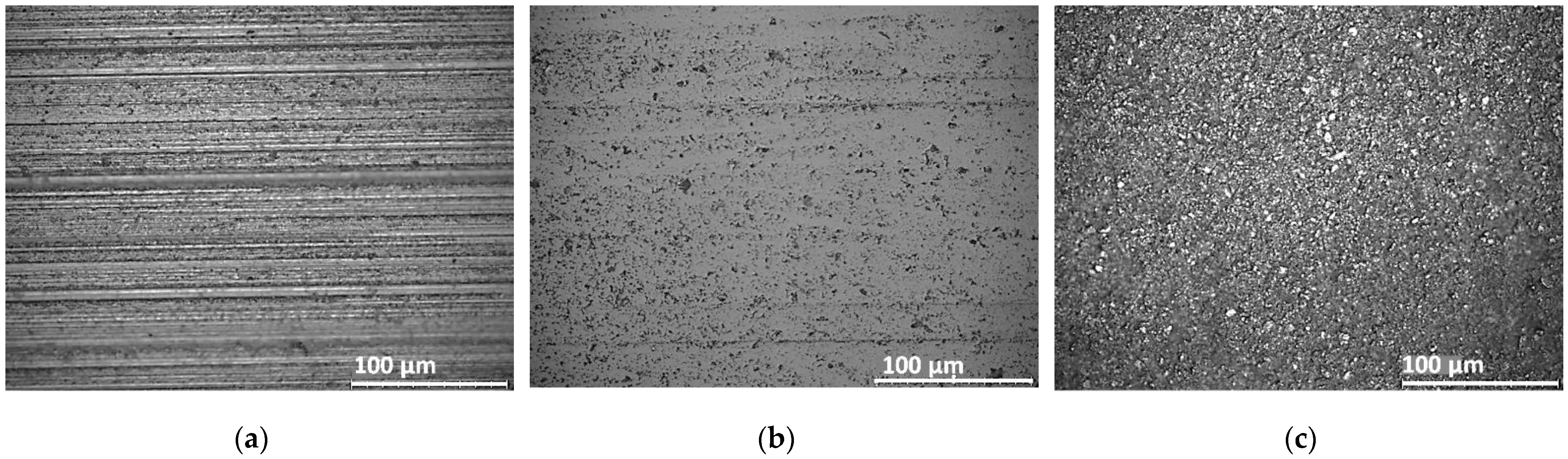
Figure 3.
Schematic representation of the dual-cathode (Cu and Cr) HiPIMS process used in this study.
Figure 3.
Schematic representation of the dual-cathode (Cu and Cr) HiPIMS process used in this study.

Figure 4.
External turning in SMT Swedturn machine. Parameters: cutting speed Vc = 220 m/min, feed rate f = 0.35 mm/rev, and depth of cut ap = 1.2 mm.
Figure 4.
External turning in SMT Swedturn machine. Parameters: cutting speed Vc = 220 m/min, feed rate f = 0.35 mm/rev, and depth of cut ap = 1.2 mm.
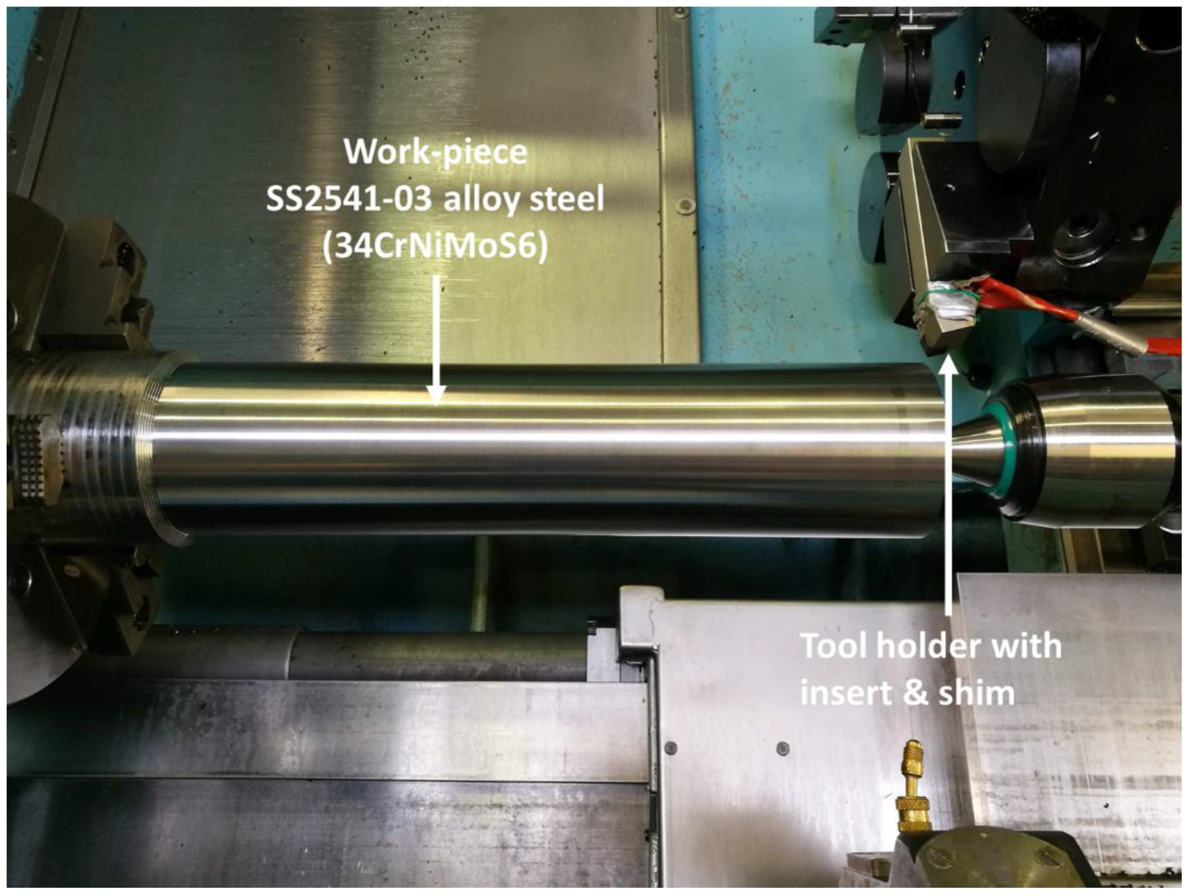
Figure 5.
SEM cross-section of Cu:CuCNx coating.
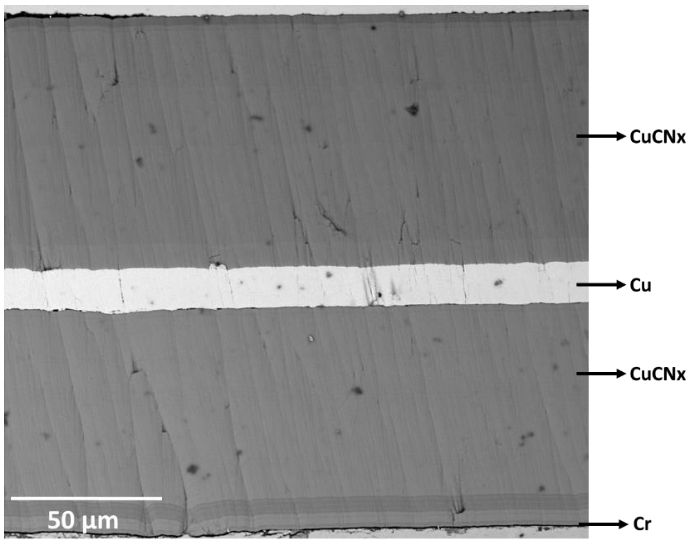
Figure 6.
(a) SEM cross-section of Cu:CuCNx coating, Cr pre-layer. (b) Surface topography of HiPIMS Cr+ ion-etched M shim.
Figure 6.
(a) SEM cross-section of Cu:CuCNx coating, Cr pre-layer. (b) Surface topography of HiPIMS Cr+ ion-etched M shim.
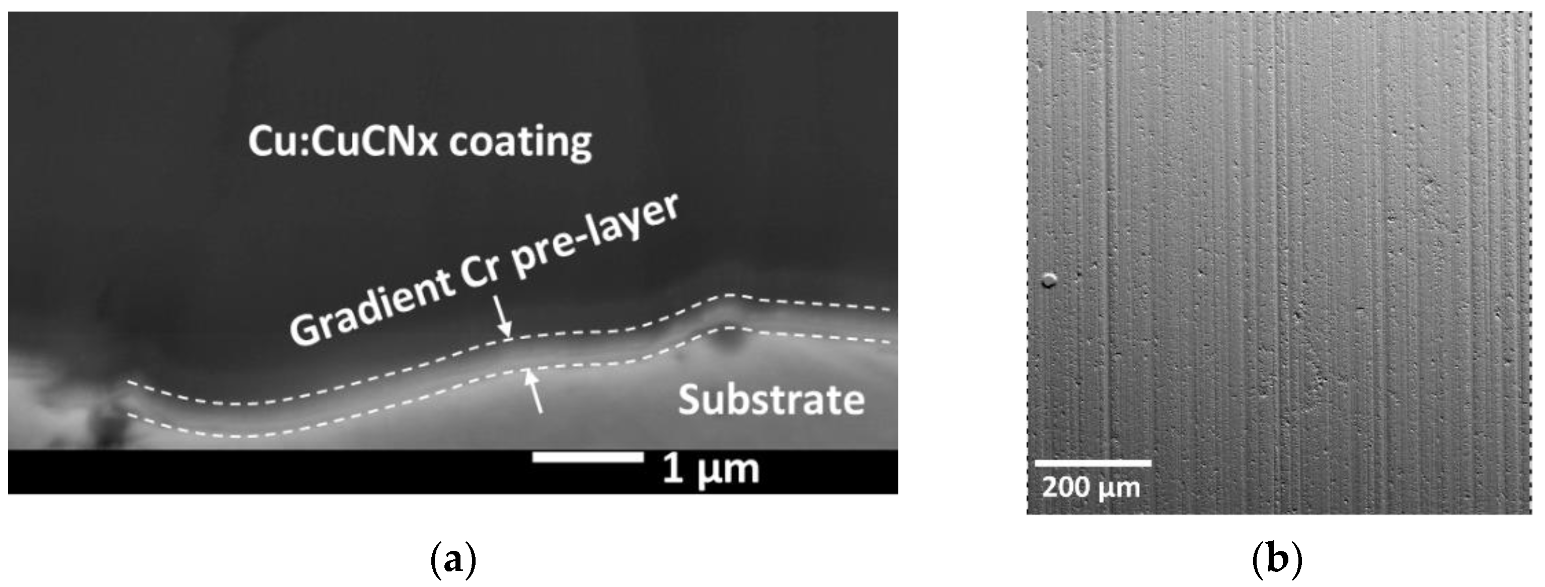
Figure 7.
Cu:CuCNx coating on (a) DP shim, (b) M shim, and (c) GB shim after heating to 300 °C then gradually cooling to ambient temperature.
Figure 7.
Cu:CuCNx coating on (a) DP shim, (b) M shim, and (c) GB shim after heating to 300 °C then gradually cooling to ambient temperature.

Figure 8.
Cu:CuCNx-coated shims after external turning: (a) M coated shim after 85 min; (b) DP coated shim after 70 min; and (c) GB coated shim after 90 min.
Figure 8.
Cu:CuCNx-coated shims after external turning: (a) M coated shim after 85 min; (b) DP coated shim after 70 min; and (c) GB coated shim after 90 min.

Table 1.
Measurement characteristics of the Mirau interferometer for WLI Zygo NewView 7300.
| Magnification | NA | Working Distance (μm) | Field of View (μm) | Optical Resolution (μm) | Vertical Resolution (nm) | Max. Slope (°) | Min. Measurable Roughness |
|---|---|---|---|---|---|---|---|
| 50× | 0.55 | 3.4 | 340 × 284 | 0.52 | <0.1 | 28.81 | 1 nm |
Table 2.
Assessment of surface-texture character by (Row A) surface isotropy and (Row B) peak-count distribution on shim surfaces before coating.
Table 2.
Assessment of surface-texture character by (Row A) surface isotropy and (Row B) peak-count distribution on shim surfaces before coating.
| M Shim | DP Shim | GB Shim | |
|---|---|---|---|
| A | 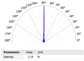 | 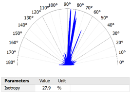 | 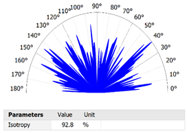 |
| B | 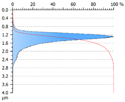 | 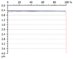 | 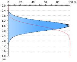 |
Table 3.
Height (amplitude) parameters of surface roughness (S-L) for different shims. For each parameter, four measurements were conducted.
Table 3.
Height (amplitude) parameters of surface roughness (S-L) for different shims. For each parameter, four measurements were conducted.
| Shim | Unit | Parameter Description | |||
|---|---|---|---|---|---|
| M | DP | GB | |||
| Ssk | −1.02 ± 0.24 | −2.77 ± 1.69 | −0.06 ± 0.04 | Skewness | |
| Sku | 5.53 ± 0.53 | 62.37 ± 41.02 | 3.35 ± 0.02 | Kurtosis | |
| Sp | 1.80 ± 0.34 | 2.02 ± 2.05 | 2.63 ± 0.46 | μm | Maximum peak height |
| Sv | 2.13 ± 0.12 | 1.82 ± 1.64 | 2.45 ± 0.12 | μm | Maximum pit height |
| Sz | 3.93 ± 0.43 | 3.84 ± 3.69 | 5.08 ± 0.52 | μm | Maximum height |
| Sq | 0.28 ± 0.02 | 0.29 ± 0.47 | 0.42 ± 0.01 | μm | Root-mean-square height |
| Sa | 0.21 ± 0.01 | 0.23 ± 0.38 | 0.33 ± 0.01 | μm | Arithmetic mean height |
Table 4.
Shim surface texture analysis before the coating process: (A) SEM images; roughness (S-L surface) areal surface texture, (B) 2D pseudo-colour view, (C) 3D view, and (D) Sk group of functional surface parameters and graphical representation.
Table 4.
Shim surface texture analysis before the coating process: (A) SEM images; roughness (S-L surface) areal surface texture, (B) 2D pseudo-colour view, (C) 3D view, and (D) Sk group of functional surface parameters and graphical representation.
| M Shim | DP Shim | GB Shim | |
|---|---|---|---|
| A | 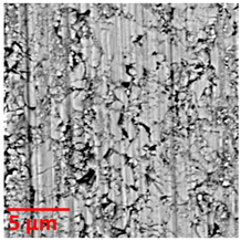 | 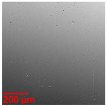 |  |
| B | 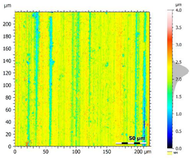 | 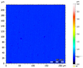 |  |
| C | 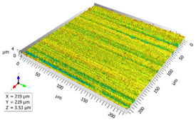 | 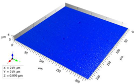 |  |
| D |  | 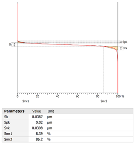 | 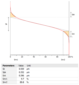 |
Table 5.
EDS elemental composition of different pretreated shim surfaces.
| W %wt. conc. | C %wt. conc. | Co %wt. conc. | O %wt. conc. | Cr %wt. conc. | |
|---|---|---|---|---|---|
| M shim | ~96.95 | ~1.35 | ~1.70 | ||
| GB shim | ~94.52 | ~1.73 | ~1.54 | ~2.21 | |
| DP shim | ~95.12 | ~1.48 | ~1.70 | ~1.71 | |
| Cr+ ion-etched GB shim | ~94.00 | ~2.32 | ~1.32 | ~2.02 | ~0.33 |
| Cr+ ion-etched DP shim | ~94.64 | ~1.48 | ~1.69 | ~1.82 | ~0.38 |
Table 6.
Thickness and EDS elemental composition of different layers of the Cu:CuCNx coating. Five measurements were conducted for each thickness.
Table 6.
Thickness and EDS elemental composition of different layers of the Cu:CuCNx coating. Five measurements were conducted for each thickness.
| Layers in Cu:CuCNx Coating | Thickness (µm) | Elemental Composition (% Wt) | Deposition Time (Hours) |
|---|---|---|---|
| Cr pre-layer | 0.5 ± 0.09 | ~55.6% Cu, 18.7 % Fe, 10.5% C, 9.9% Cr, 3.8% O, 1.6% N | 0.5 |
| CuCNx (1st layer) | 81.68 ± 1.17 | ~62.59% Cu, 23.44% C, 11.45% N, 2.52% O | 41 |
| Cu (intermediate layer) | 19.92 ± 1.42 | ~95.98% Cu, 4.02% O | 10 |
| CuCNx (2nd layer) | 90.18 ± 0.64 | ~60.31% Cu, 23.94% C, 13.22% N, 2.54% O | 45 |
Table 7.
Machining test results. Five wear measurements were taken for each insert.
| Machining Parameters | Type of Coated Shim | Insert Wear (µm) | Total Machining Time Before the Coating Breaks (minutes) | Comments |
|---|---|---|---|---|
| Vc = 220 m/min f = 0.35 mm/rev ap = 1.2 mm | M | 279.15 ± 2.79 (after 80 min) | ~85 | Coating broke between 80 and 85 min. |
| GB | 249.79 ± 4.39 (after 80 min) | >90 | The coated shim could still be used after 90 min. | |
| DP | 261.80 ± 3.20 (after 65 min) | ~70 | Coating broke between 65 and 70 min. |
Publisher’s Note: MDPI stays neutral with regard to jurisdictional claims in published maps and institutional affiliations. |
© 2022 by the authors. Licensee MDPI, Basel, Switzerland. This article is an open access article distributed under the terms and conditions of the Creative Commons Attribution (CC BY) license (https://creativecommons.org/licenses/by/4.0/).
Share and Cite
MDPI and ACS Style
Rashid, M.M.-U.; Tomkowski, R.; Archenti, A. Effect of Surface Pre-Treatment on the Adhesion between HiPIMS Thick Cu:CuCNx Coating and WC-Co Shim. Coatings 2022, 12, 1484. https://doi.org/10.3390/coatings12101484
AMA Style
Rashid MM-U, Tomkowski R, Archenti A. Effect of Surface Pre-Treatment on the Adhesion between HiPIMS Thick Cu:CuCNx Coating and WC-Co Shim. Coatings. 2022; 12(10):1484. https://doi.org/10.3390/coatings12101484
Chicago/Turabian StyleRashid, Md Masud-Ur, Robert Tomkowski, and Andreas Archenti. 2022. "Effect of Surface Pre-Treatment on the Adhesion between HiPIMS Thick Cu:CuCNx Coating and WC-Co Shim" Coatings 12, no. 10: 1484. https://doi.org/10.3390/coatings12101484
Note that from the first issue of 2016, this journal uses article numbers instead of page numbers. See further details here.