Article

High Temperature Corrosion Behaviour of Aluminide-Coated Cast Iron for an Exhaust Manifold Application

by
Panya Kerdbua
1,
Mohammad Hassan Shirani Bidabadi
2,
Walairat Chandra-ambhorn
3 and
Somrerk Chandra-ambhorn
2,*
1
Department of Production Engineering, Faculty of Engineering, King Mongkut’s University of Technology North Bangkok, 1518, Pracharat 1 Road, Bangsue, Bangkok 10800, Thailand
2
High Temperature Corrosion Research Centre, Department of Materials and Production Technology Engineering, Faculty of Engineering, King Mongkut’s University of Technology North Bangkok, 1518, Pracharat 1 Road, Bangsue, Bangkok 10800, Thailand
3
Department of Chemical Engineering, Faculty of Engineering, King Mongkut’s Institute of Technology Ladkrabang, 1 Soi Chalongkrung 1, Ladkrabang, Bangkok 10520, Thailand
*
Author to whom correspondence should be addressed.
Coatings 2020, 10(8), 705; https://doi.org/10.3390/coatings10080705
Submission received: 2 July 2020 / Revised: 18 July 2020 / Accepted: 20 July 2020 / Published: 22 July 2020
(This article belongs to the Section Corrosion, Wear and Erosion)

Abstract

:
To reduce the pollution emission from vehicles, an improvement on the combustion process is expected, leading to increased exhaust gas temperature. As a result, the development of new materials for an exhaust manifold used at higher temperatures is required. A cost-effective cast iron exhaust manifold treated by aluminising pack cementation was developed in the present work to combat the high temperature corrosion. Its kinetics under cyclic oxidation in N2–12%O2–10%H2O at 850 °C was parabolic with the rate constant (kp) of 5.66 × 10⁻¹² g2 cm–4 s–1, about two orders of magnitude lower than that of the bare cast iron, which indicated the protectiveness of the applied coating. These results relate to the protective alumina formation for the aluminised cast iron and the formation of the less protective iron oxides for the bare cast iron after oxidation, as evidenced by the XRD and Raman spectroscopy results. The addition of 10% water vapour to N2–12%O2 thickened the aluminide layer from 344 μm for the sample oxidised in dry atmosphere to 409 μm for the sample oxidised humidified one. It accelerated the oxidation rate of the aluminised cast iron as the kp value increased by 8.5 times, and also increased the hardness of the aluminised surface, as it was 364 HV for the sample exposed to dry atmosphere and 420 HV for the sample exposed to humidified one. The latter result implied the possibility of the hydrogen dissolution into the metal surface. The roles of hydroxyl ion and dissolved hydrogen on the oxidation and evolution of the aluminide layer after exposure to water vapour were proposed.

1. Introduction

Towards a low carbon society, a combustion process in the automobile engine has been improved and, as a result, the exhaust gas temperature tends to be raised [1,2,3]. Traditionally the actual air-to-fuel ratio per the ideal air-to-fuel ratio, the λ value, is about 0.9, which is the optimised value for the combustion efficiency and material durability [4,5]. In this case, the excess fuel can cool the engine as well as the exhaust gas [4]. In order to combust the fuel more efficiently, the λ value has to be increased, and consequently the cooling effect due to the excess fuel is eliminated, resulting in the increased exhaust gas temperature, which can be up to about 1050 °C [4]. Thus, there has been a quest for the new exhaust system material to be used in this more aggressive condition [1,2,6,7,8,9,10,11,12] particularly for a part at the upstream exhaust system—the exhaust manifold [4,13].
The first group of materials that can be used as an exhaust manifold is cast irons [1,2,6,7,8,9,10,11]. They may be the conventional grades like flake or nodular graphite cast irons [7,8]. To increase the service temperature up to 800 °C, Si and Mo are added to the ferritic cast iron by about 4–5 and 0.5–1 wt.%, respectively, giving the SiMo51 cast iron [9,10]. Ekström et al. [9] found that the addition of Cr with the contents of 0.5 and 1 wt.% to the SiMo51 cast iron could improve the high temperature oxidation resistance of the alloy in air at 700–800 °C, which related to the formation of silica and Cr-containing oxide at the oxide–metal interface. However, the Cr-containing oxide was not formed when the cast iron was oxidised in the exhaust gas, which was argued to be due to the water vapour effect on volatilising the Cr-species from the oxide [9]. Apart from the cast iron exhaust manifold, the other group of materials for this application is stainless steels [1,2,12,13]. Brady et al. [2] reported that the oxidation resistance of the chromia-forming stainless steels used for the exhaust system could be improved by the addition of Cr and Ni. For the test in air with 10% of water vapour at 800 °C, the excessive mass loss and spallation were observed for the CF8CP austenitic stainless steel containing 19 wt.% Cr and 13 wt.% Ni, while less mass loss was found in the TMA 4705 stainless steel, which contains higher contents of those elements, 26 wt.% of Cr and 21 wt.% of Ni [2]. When comparing to those chromia-forming alloys, the alumina-forming stainless steel containing 25 wt.% Cr, 14 wt.% Ni and 3.5 wt.% Al was found to exhibit the superior high temperature oxidation resistance because of the formation of the protective alumina scale on the steel surface [2]. These results shed light to the idea to develop a cost-effective exhaust manifold, which is made of cheap cast iron but with its surface alloyed by Al in order to form the protective alumina during service at high temperatures.
One of the cost-effective methods to increase the Al content on the alloy surface is aluminising pack cementation. This method has been applied to steels [14,15,16], stainless steels [17,18], nickel and nickel-based alloys [19,20,21,22,23]. Wang et al. [8] has recently developed the aluminide-coated spheroidal cast iron and investigated its high temperature oxidation behaviour in air. However, until now, the understanding in the high temperature corrosion behaviour of this surface alloy under the exhaust gas has been relatively limited because of the complicated gas composition containing O2, CO2, CO, SO2, NOx, N2, unburned fuel and water vapour which existed in the range of 2–12% v/v [1,2,3,9]. It has been widely reported that water vapour in the atmosphere was detrimental for the use of ferrous alloys at high temperatures since it tended to accelerate the alloy oxidation rate [11,24,25,26,27,28,29,30,31]. However, its effect on the oxidation behaviour of the alloys after being aluminised has been far more limited [15,32,33,34]. Among these works, the oxidation mechanism in the humidified atmosphere of the cast iron treated by aluminising pack cementation has rarely been reported. Thus, the objective of this work was firstly to develop a new exhaust manifold material by aluminising the cast iron using pack cementation and; therefore, investigate its oxidation mechanisms in the atmospheres without and with water vapour.

2. Materials and Methods

The exhaust manifold material made of cast iron was used in this study. Figure 1 presents its microstructure exhibiting the distribution of vermicular and nodular graphite in a matrix, showing that the cast iron was the compacted-graphite type typically alloyed with 3.1–4.0 wt.% C and 1.7–3.0 wt.% Si, 0.015–0.035 wt.% Mg and 0.06–0.13 wt.% Ti [35]. The sample was cut into the dimensions of 8 mm × 10 mm × 5 mm. It was then polished on SiC-papers up to 600 grit, cleaned by acetone in an ultrasonic machine and dried in air. Afterwards, it was aluminised at 1050 °C for 5 h in the pack consisting of 25 wt.% Al (particle size: ~70 µm), 70 wt.% Al2O3 (~40 µm) and 5 wt.% NH4Cl in argon (purity: 99.995%). The horizontal tube furnace was used with the tube inner and outer diameters of 4.8 and 5 cm and with the tube length of 58 cm.
After aluminising, the sample was taken for the cyclic oxidation test at 850 °C for 14 cycles. In each cycle, the sample was heated up from room temperature to 850 °C and held at this temperature for 8 h in the atmosphere, containing 12% of oxygen without water vapour (N2–12O2) and with 10% of water vapour (N2–12O2–10H2O), and then cooled down in a furnace to room temperature under laboratory air. The bare cast iron was also tested in N2–12O2–10H2O to compare its oxidation behaviour with the cast iron treated by aluminising. To prepare the atmosphere containing water vapour, the N2–12O2 gas mixture was flowed into the flask containing water with the temperature of 44.5 °C. From the thermodynamic calculation using Barin’s data [36], water vapour at this temperature was 10% by volume. In this manner, the N2–12O2–10H2O gas mixture was produced and further fed to the furnace.
For the physico-chemical characterisation, an X-ray diffractometer (Bruker AXS D8 DISCOVER, Billerica, MA, USA) using Kα (1.5406 Å) Cu radiation and Laser Raman spectroscopy (Renishaw RM 1000, Glouchestershire, UK) were performed for phase identification. A scanning electron microscope (SEM, JSM-6610LV, Tokyo, Japan) equipped with an energy dispersive X-ray analyser was used for imaging and elemental analyses.

3. Results

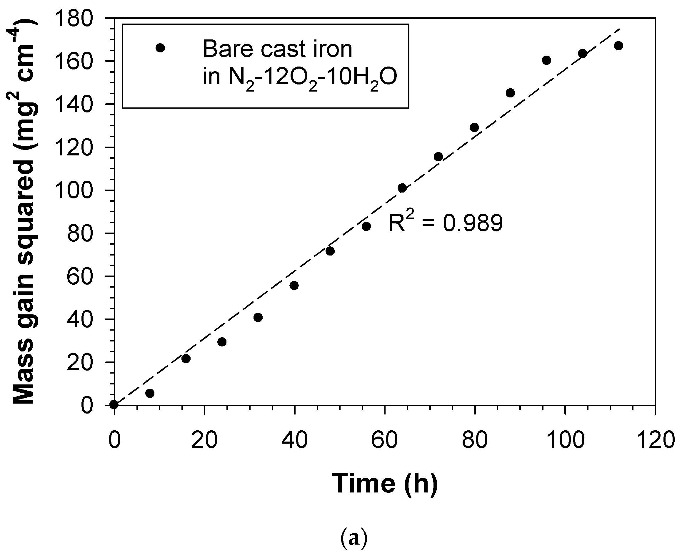
3.1. Mass Gain of the Bare and Aluminide-Coated Cast Irons after Oxidation

Figure 2 shows mass gains of the bare and aluminide-coated cast irons as a function of the oxidation cycle. It can be seen that aluminising significantly reduced the oxidation rate of the cast iron in N2–12O2–10H2O. For example, after oxidation for 14 cycles, mass gains of the bare and aluminide-coated cast irons were 12.91 and 1.64 mg cm–2, respectively, showing 87% reduction in mass gain after aluminising treatment. It can also be seen that increasing water vapour in the atmosphere enhanced the oxidation. For example, after 14 testing cycles, mass gains of the aluminide-coated cast irons oxidised in N2–12O2 and N2–12O2–10H2O were 0.49 and 1.64 mg cm–2, respectively.

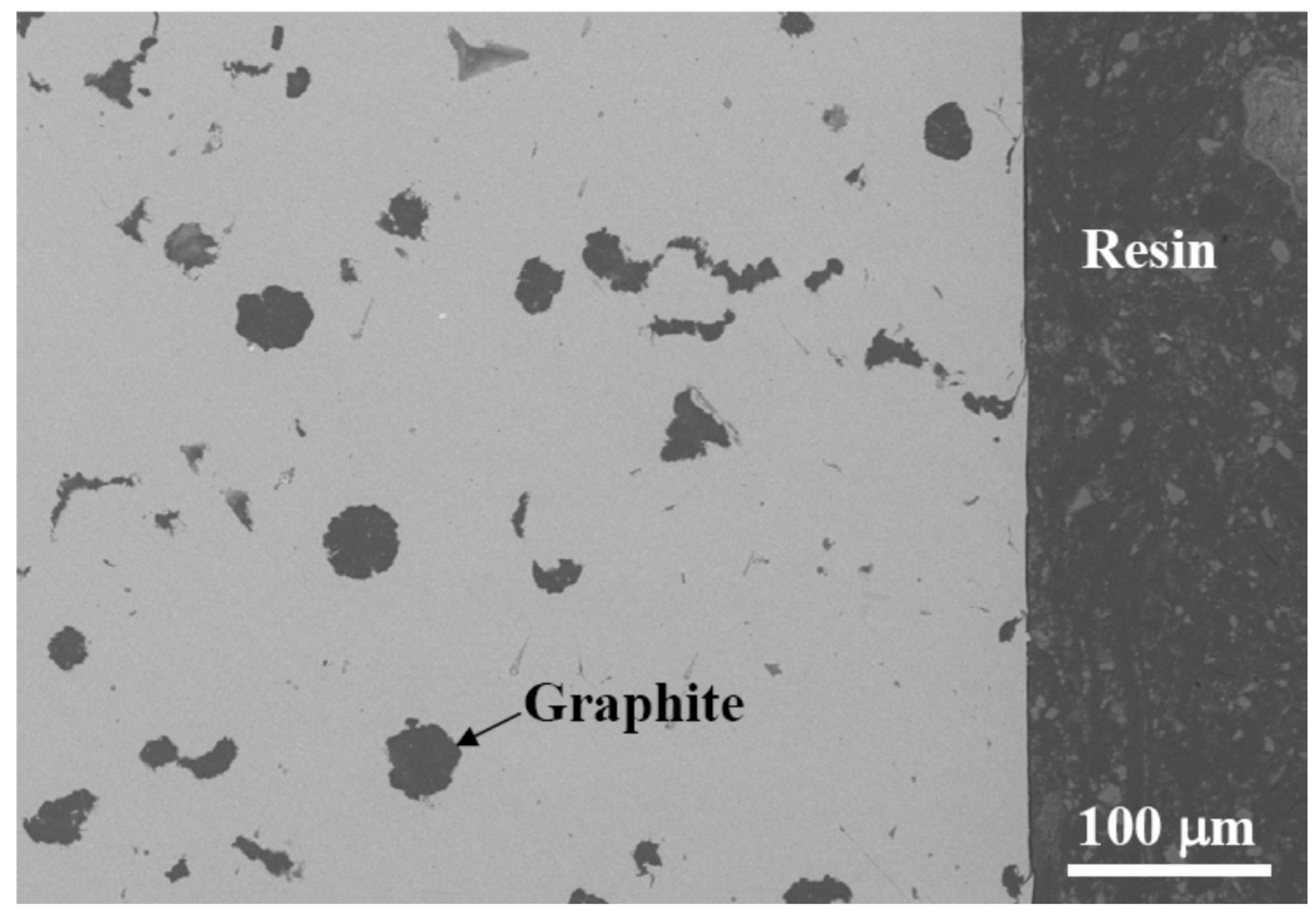
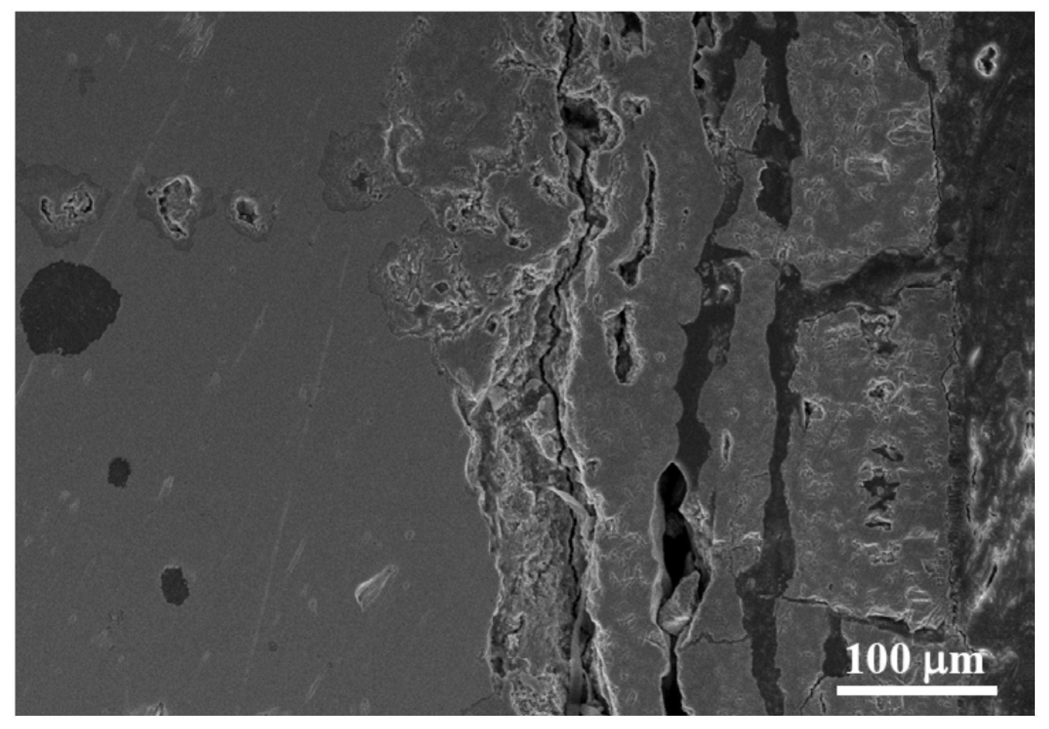
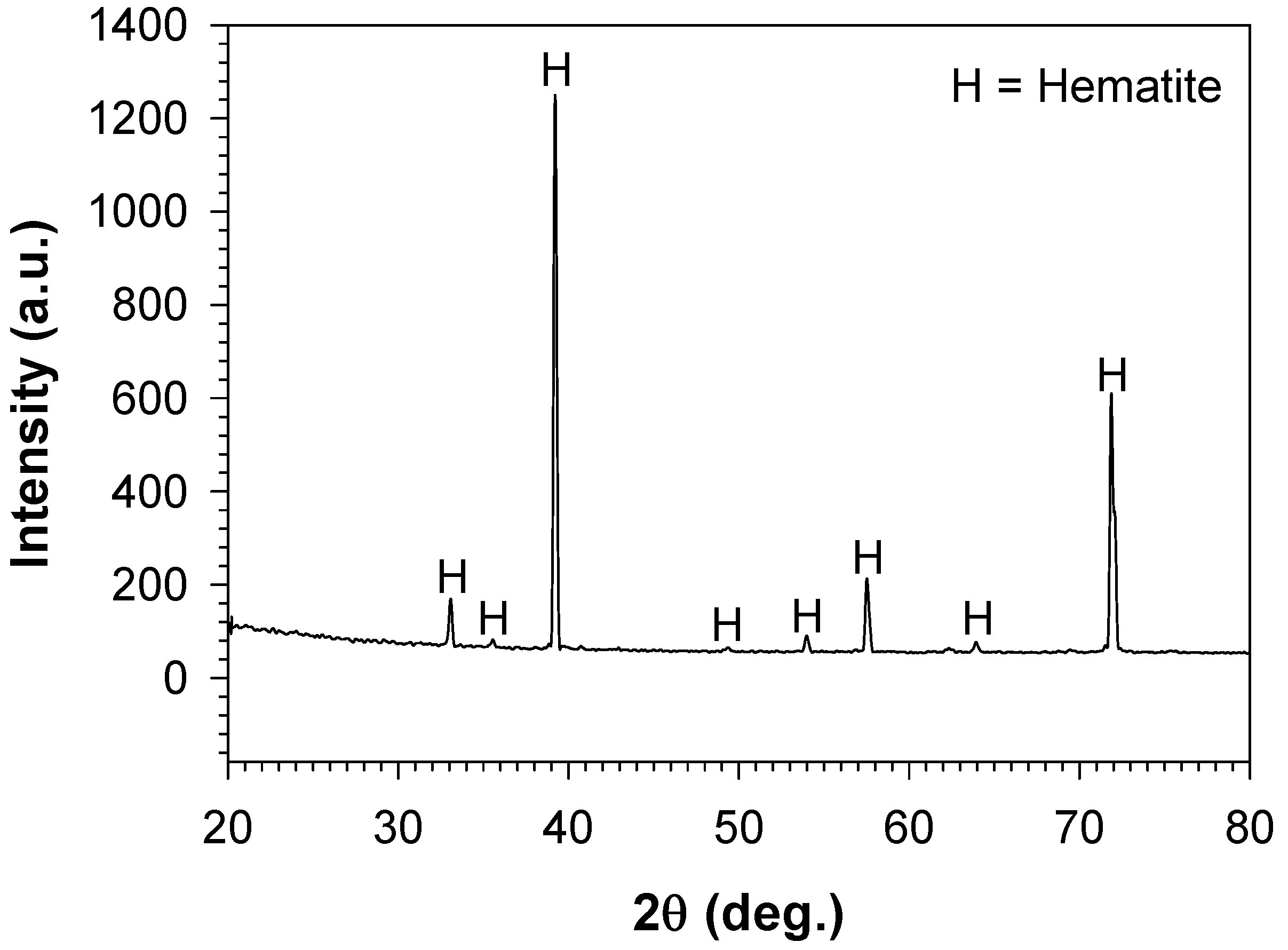
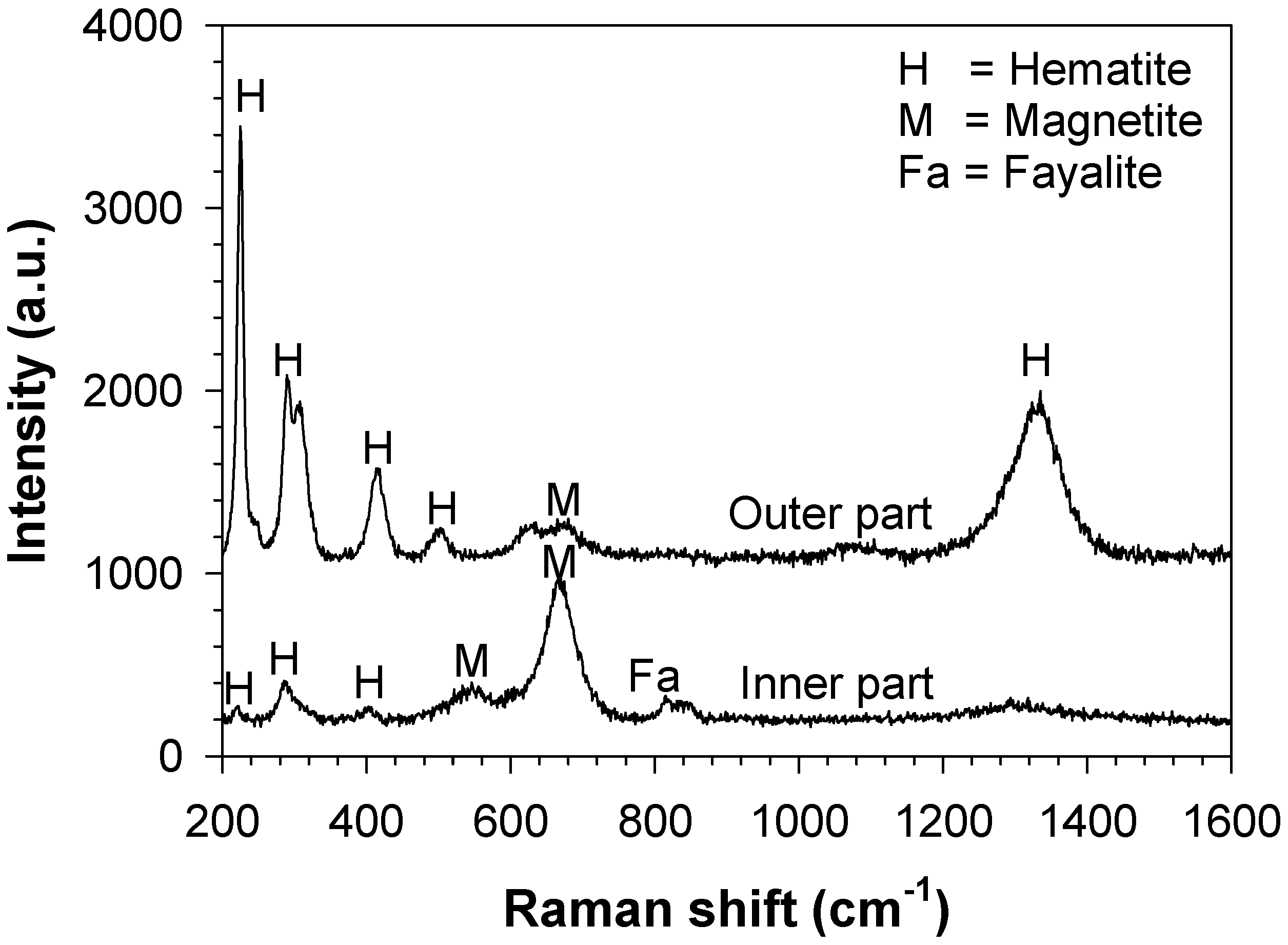
3.2. Characterisation of the Bare Cast Iron after Oxidation

Figure 3 presents the SEM cross-section of the bare cast iron oxidised in N2–12O2–10H2O after cyclic oxidation for 14 cycles. The scale was rather porous and contained cracks which indicated the brittle behaviour of the scale formed in the atmosphere containing water vapour. Decarburisation of the graphite was also observed.
Figure 4. depicts the X-ray diffraction (XRD) pattern of the bare cast iron after cyclic oxidation in N2–12O2–10H2O for 14 cycles. Only hematite peaks were detected. Since the analytical depth of the XRD analysis was about 1–3 µm [37], this result indicated that hematite existed as the outermost layer of the scale. To further characterise the inner oxide scale, the sample was cross-sectioned and Raman spectroscopy was applied to identify the oxide phases at the inner and the outer parts of the scale as shown in Figure 5. It can be seen that at the outer part of the scale, the hematite peaks were dominantly observed while a slight signal of magnetite was detected. On the contrary, at the inner part of the scale, the strong peaks of magnetite were observed. Hematite was also found but with lower intensities than the ones detected at the outer part of the scale. The peak of fayalite was also observed. The results from XRD and Raman patterns indicated that hematite existed as the outer layer, whereas magnetite and fayalite were in the inner part of the oxide scale. Comparing to literature, the recent work on the oxidation of the spheroidal cast iron containing 4.4 wt.% Si and 0.5 wt.% Mo in humid air at 700 °C has reported the formation of hematite as the outer external scale and the formation of magnetite and fayalite as the inner scale by using the XRD technique [11]. However, it is noted that wustite was not observed in the scale in the present work.

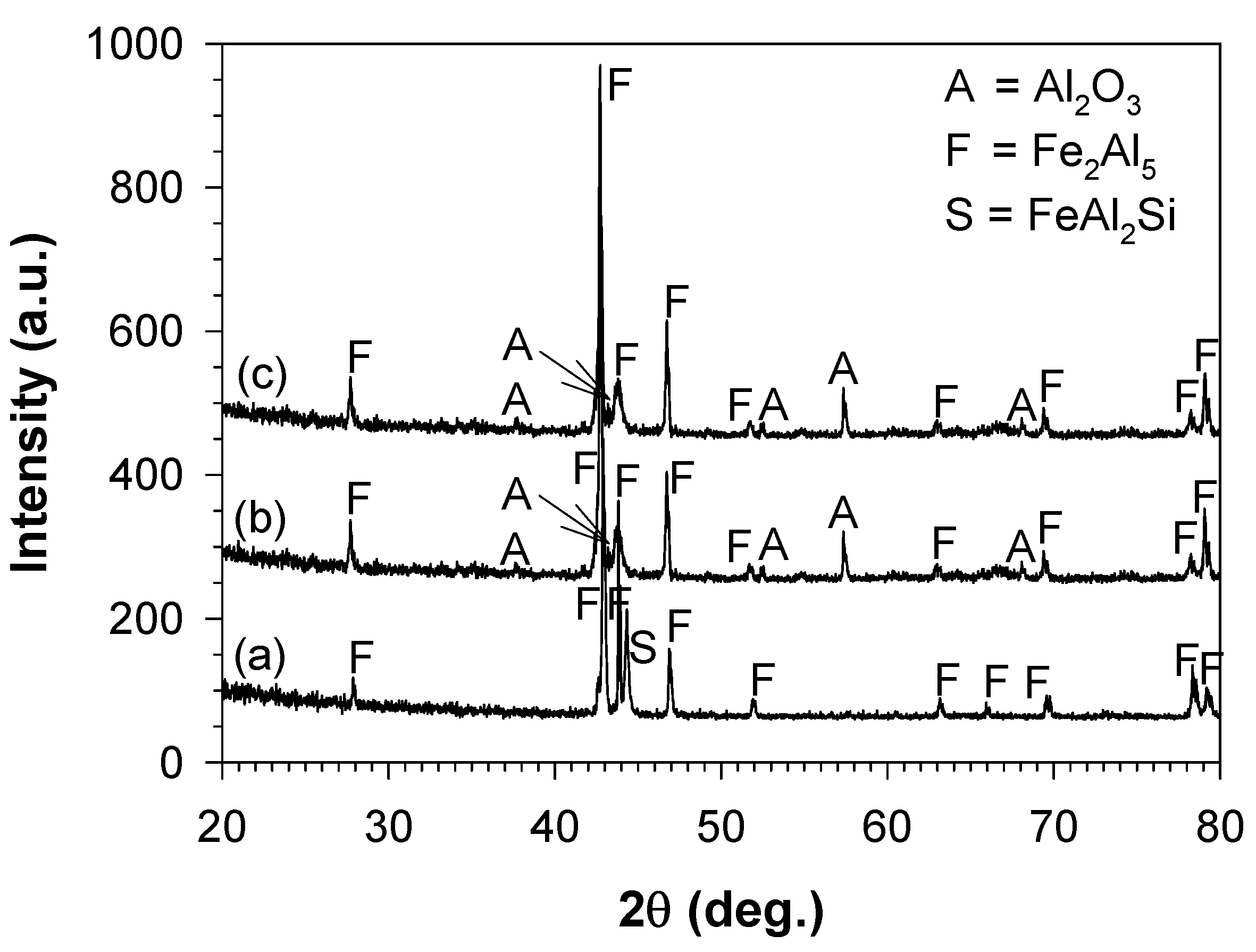
3.3. Characterisation of the Aluminide-Coated Cast Iron before Oxidation

Figure 6a depicts the SEM cross-section of the cast iron after aluminising. The aluminide layer consisted of two distinct parts: the outer and inner sub-layers. The outer sub-layer which was adjacent to the atmosphere mainly consisted of the darker matrix dispersed by white phases. The inner sub-layer which was adjacent to the metal substrate consisted of the matrix precipitated by elongated darker phases. By measuring from two SEM images, the thicknesses of the inner and outer sub-layers were respectively 35 ± 3 µm and 219 ± 67 µm, giving the total aluminide thickness of about 254 µm.
To characterise the outer sub-layer, the XRD technique was applied on the surface of the sample giving the pattern (a) shown in Figure 7. It can be seen that the major peaks observed were Fe2Al5. The most intense peak of FeAl2Si was also detected. To further characterise the phases located deeper from the surface than the XRD analytical depth, the energy dispersive X-ray analysis (EDX) was applied to the cross-sectioned sample. By measuring on three different areas, the atomic ratio of aluminium to iron in the matrix of the outer scale was in the range of 1.99 to 2.25 at.%. The dispersed white phases contained a significant amount of silicon by 3.3 at.%. For the inner sub-layer, the atomic ratio of aluminium to iron in the matrix was 1.05:1, showing that this phase should be FeAl.

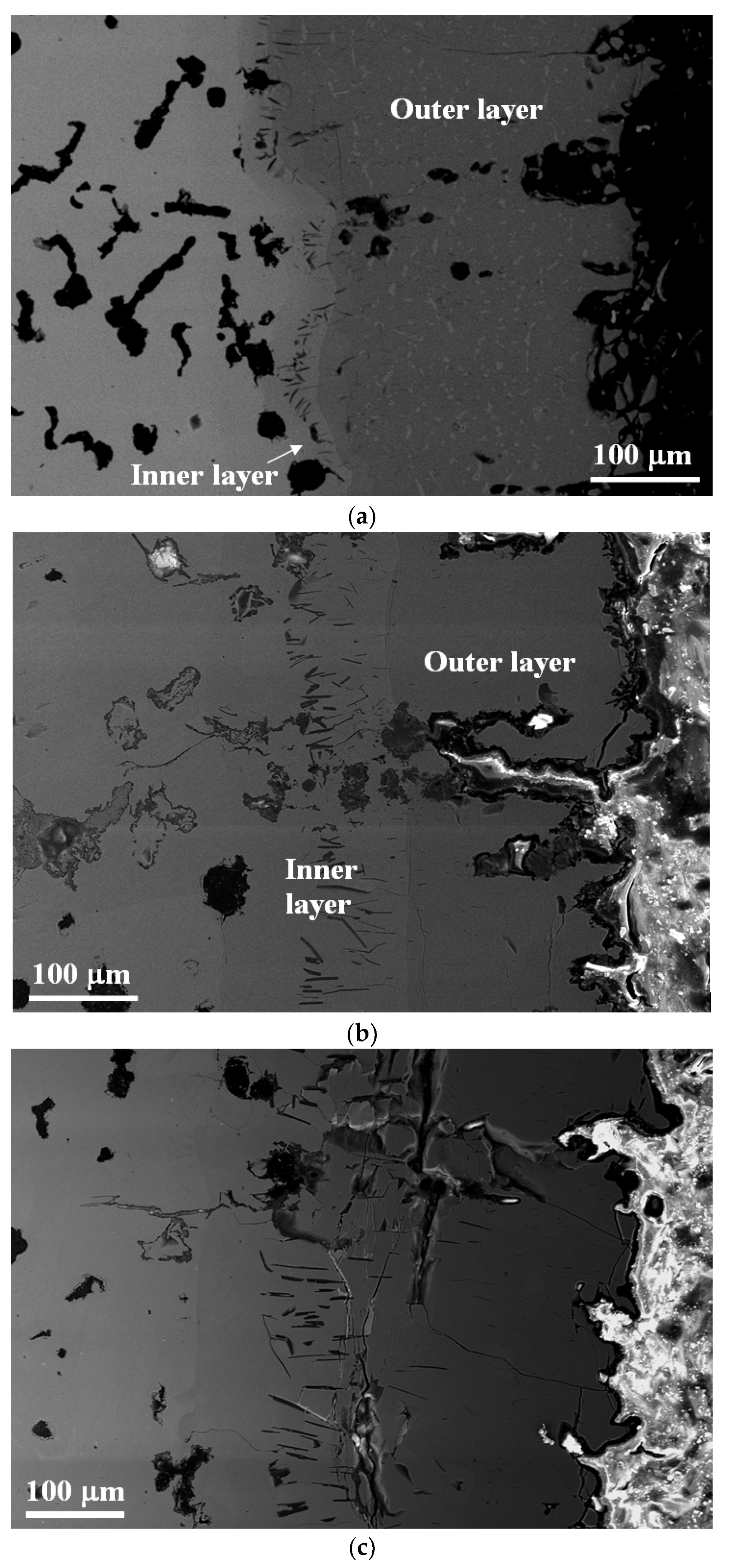
3.4. Characterisation of the Aluminide-Coated Cast Iron after Oxidation

Figure 6b shows the SEM cross-section of the aluminide-coated cast iron after oxidation in N2–12O2 for 14 cycles. It can be seen that, after oxidation, most of the aluminide layer remained unattacked and still consisted of two distinct parts, like the one observed before oxidation. However, the inner part was considerably thicker to be 153 ± 12 µm thick while the outer layer was slightly thinner to be 191 ± 11 µm thick. These two parts gave the total thickness of the aluminide layer of about 344 µm, which was thicker than the one before oxidation (254 µm). Furthermore, it should be noted that, even though a large crack was contained in the outer sub-layer, the aluminide layer was still protective compared with the aluminide layer oxidised in N2–12O2–10H2O (Figure 2).
For the outer sub-layer, pattern (b) in Figure 7 shows the XRD result of the aluminide-coated cast iron after oxidation in N2–12O2 for 14 cycles. Comparing to the XRD peaks of the aluminide layer before oxidation, the Fe2Al5 peaks were still dominantly observed, whereas the peaks of Al2O3 were additionally detected. The existence of the latter peaks confirmed the formation of the protective alumina layer after oxidation. By using the alumina density of 3.95 g cm–2 [15], the alumina thickness calculated from the mass gain after 14 oxidation cycles was 2.64 µm. The thickness of alumina could be lower than this value because of the increased surface area due to the rough surface [15]. Because the alumina layer could be relatively thin and the aluminide layer tended to be fractured along the metal surface, as shown in Figure 6b, the alumina layer was then not obviously observed in the SEM image, even though its existence was confirmed by the XRD. It can be further seen from Figure 6b that the Fe3(Al,Si)5, once observed as the white phase dispersed in the matrix of the outer sub-layer of the aluminide-coated sample before oxidation, disappeared. The outer aluminide sub-layer; thus, looks homogeneous with the atomic ratio of aluminium to iron in the range of 2.36 to 1.98 at the locations 14 to 116 µm away from the surface. For the inner sub-layer, comparing to the aluminide-coated sample before oxidation, this region still consisted of the matrix precipitated by elongated phases. The EDX analysis showed that the atomic ratio of aluminium to iron of the matrix was 1.12:1, respectively, indicating that this phase should still be FeAl.
Figure 6c shows the SEM cross-section of the aluminide-coated cast iron after oxidation in N2–12O2–10H2O for 14 cycles. Comparing to the aluminide-coated sample oxidised in N2–12O2, the aluminide layer exposed to this atmosphere was considerably thicker, at 409 µm, with less obvious contrast between two sub-layers. The XRD result of aluminide-coated sample oxidised in this condition for 14 cycles is shown in pattern (c) of Figure 7. The strong peaks of Fe2Al5 and the existence of Al2O3 peaks were observed. The EDX spot analysis showed that the atomic ratio of aluminium to iron of the aluminide layer was reduced from 2.36 to 0.81 at the locations 136 to 362 µm away from the metal surface, respectively.

4. Discussion

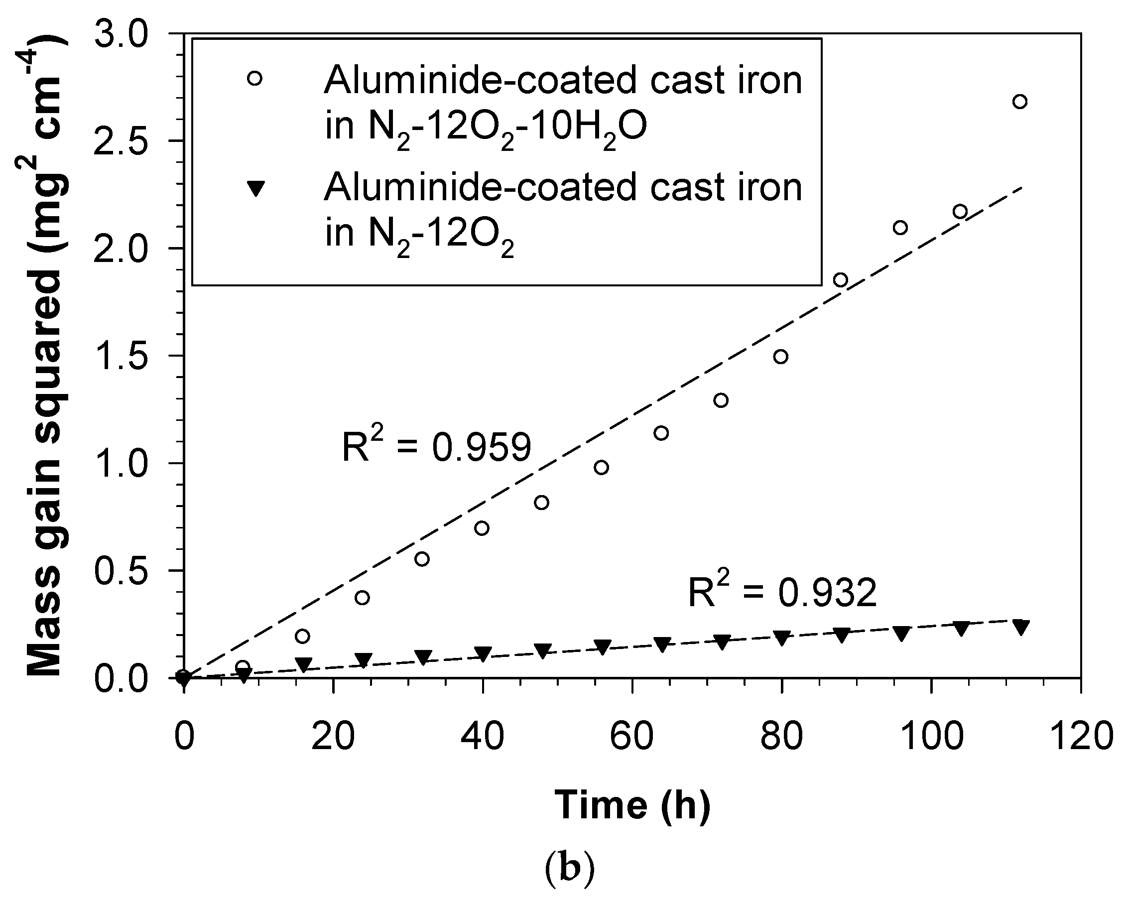
4.1. Oxidation Kinetics

Mass gain from Figure 2 was squared and plotted as a function of time by considering that each testing cycle gave 8 h of isothermal oxidation. The linear relationship between the square of mass gain and time can be seen in Figure 8. It can be expressed in the following form [37,38]:
(Δm/A)2 = kpt
where (Δm/A) is the mass gain, which is the change of mass with respect to the mass before oxidation per unit surface area of the sample; kp is the parabolic rate constant; and t is the oxidation period of time. The parabolic relation according to Equation (1) indicates that the rate limiting step of the oxidation was diffusion-controlled and the oxidation rate reduces when the oxidation period is longer [37,38]. From this figure, the parabolic rate constant of the bare cast iron oxidised in N2–12O2–10H2O was calculated at 4.34 × 10⁻¹⁰ g2 cm–4 s–1. It was higher than the parabolic rate constants of the aluminide-coated samples, which were 6.69 × 10⁻¹³ and 5.66 × 10⁻¹² g2 cm–4 s–1 for the oxidation in N2–12O2 and N2–12O2–10H2O, respectively. Comparing with literature, when the studied cast iron was treated by aluminising, its parabolic rate constants reduced and approached those of the alumina-forming alloys, which were in the range of 1 × 10–13 to 6.2 × 10⁻¹¹ g2 cm–4 s–1 [39,40,41,42,43,44]. In the case of iron, oxidation rate also tends to be higher when water vapor is present in the atmosphere [45].

4.2. Formation of Thermal Oxide Scales on the Bare Cast Iron

At equilibrium, the standard Gibbs free energy for the oxide formation reaction is proportional to the absolute temperature T and the logarithm of the equilibrium oxygen partial pressure, and may also be written in the form of A–BT where A and B are, respectively, the standard enthalpy and entropy for the oxide formation reaction [46,47]. From these relations, the logarithm of the equilibrium oxygen partial pressure can be expressed as a linear function of the inverse temperature, as comprehensively derived in the literature [46,47]. Figure 9 presents this relation for the formation of oxides relevant to the present study (i.e., hematite, magnetite, wustite, fayalite, silica and alumina). The diagram was constructed using standard thermodynamic data compiled by Kubaschewski and Evans [48].
For the bare cast iron oxidised in N2–12O2–10H2O, XRD and Raman patterns showed that hematite, magnetite and fayalite were formed. To analyse the thermodynamic stability of these oxides, the partial pressure of oxygen in the atmosphere has to be primarily determined. Oxygen in the atmosphere could be from the oxygen directly fed to the reactor (0.12 bar) or the oxygen dissociated from water vapour. For one mole of N2–12O2–10H2O, it was calculated using standard thermodynamic data [48] that the amount of oxygen dissociated from water vapour at equilibrium of the reaction H2O = H2 + (1/2)O2 was very small (i.e., 1.05 × 10⁻⁹ mol at 850 °C). Thus the partial pressure of oxygen in this atmosphere was about the partial pressure of oxygen directly fed to the reactor (0.12 bar). This oxygen partial pressure was clearly higher than the ones at equilibrium of the hematite, magnetite and fayalite formation as shown in Figure 9. The formations of these oxides were then thermodynamically possible.
However, wustite was absent from the scale even though thermodynamics indicates its feasibility to be formed. It was reported by Ahtoy [49] that, for the silicon-containing steel oxidised in water vapour, silicon oxide and wustite were formed in the early period of oxidation. When time elapsed, these two oxides reacted to each other and formed fayalite [49]. From the calculation using standard data [48] at 850 °C, the reaction SiO2 + 2FeO = Fe2SiO4 is thermodynamically possible at the standard state since its Gibbs free energy is negative, that is −25,714 J. In addition, Nishimoto et al. [50] applied the EBSD technique to analyse the scale formed on the silicon-containing steel oxidised in air, and found that increasing Si in the steel tended to reduce wustite while fayalite formed. The diffusivity of iron through fayalite was reported to be lower than that through wustite [49,50,51]. Thus, when fayalite formed, the outward diffusion of iron to form iron oxides was reduced. This led to the substantial formation of the iron oxides which had higher ratios of oxygen to iron (i.e., hematite or magnetite), as observed in the previous work [50] as well as the present one.

4.3. Formation of the Aluminide Layer after Aluminising

To analyse the stability of Fe–Al intermetallic compounds, it is necessary to determine the standard Gibbs free energies of their formation at high temperatures. In this analysis, the Ellingham approximation was adopted. It was assumed that the standard enthalpy and entropy of reaction did not depend on temperature [46,47]. Maitra and Gupta [52] reported that Gibbs free energies of formation of FeAl3, Fe2Al5, FeAl2 and FeAl at 900 °C were −93.91, −168.58, −77.36 and −54.7 kJ.mol–1, respectively. Kubaschewski and Evans [48] reported the values of the enthalpies of formation of FeAl3, FeAl2 and FeAl at 25 °C, as well as the latent heat of fusion of aluminium at its melting point. From these data [48], the standard enthalpies of formation of those three compounds from solid iron and liquid aluminium at 900 °C can be calculated. For Fe2Al5, literature reported the values of the enthalpy of formation of solid Fe2Al5 from liquid iron and liquid aluminium [53] and the latent heat of fusion of iron at its melting point [48]. From these data [48,53], the standard enthalpy of formation of Fe2Al5 from solid iron and liquid aluminium at 900 °C could also be derived. When the standard Gibbs free energies and enthalpies of formations of those compounds (FeAl3, Fe2Al5, FeAl2 and FeAl) at 900 °C were known, their standard entropies of formation at that temperature could be obtained. By the Ellingham approximation, the standard enthalpies and entropies of formation at 900 °C were considered to be same as the ones at other temperatures. Thus, the standard Gibbs free energies to form Fe–Al compounds from solid iron and one mole of liquid aluminium were calculated at different temperatures, as shown in Figure 10. At the standard state, all the Fe–Al compounds (FeAl3, Fe2Al5, FeAl2 and FeAl) are feasible to form at the aluminising temperature of 1050 °C because their Gibbs free energies are negative. However, some of them might not be observed if the rates of their formation were too slow.
From the characterisation results of the outer aluminide sub-layer, Fe2Al5 was detected at the surface by XRD. It was reported for the Fe–Al system that FeAl2 had the atomic ratio of aluminium to iron in the range of 1.91 to 2.02, whereas Fe2Al5 had the ratio in the range of 2.33 to 2.74 [52]. As previously reported in Section 3.3, the atomic ratio of aluminium to iron of the matrix of the outer sub-layer of the aluminide-coated sample was in the range of 1.99 to 2.25 at.%. Thus the chemical formula of the matrix should lie between FeAl2 and Fe2Al5. The existence of these two phases in the same layer was also reported in the aluminide coating of the hot-dipped low carbon steel [54].

4.4. Evolution of the Aluminide Layer during Oxidation

After oxidation in N2–12O2, alumina was formed at the surface as observed by XRD. This is because the oxygen partial pressure in the atmosphere (0.12 bar) was drastically higher than the one at equilibrium of the alumina formation, as shown in Figure 9. It was reported that alumina was grown at high temperatures mainly by the oxygen inward diffusion [15,55,56,57], while the outward aluminium diffusion was also possible [57]. The total aluminide layer was thicker than that before oxidation, indicating the diffusion of aluminium into the base cast iron. The dilution of aluminium after oxidation contributed to the increased ratio of iron to aluminium in the aluminide layer and the thicker inner sub-layer. It was also reported that the solubility of silicon in FeAl of the quenched specimen was in the range of 10.38 to 16.24 at.% at the temperature range of 800 to 1020 °C [52]. These values were substantially higher than the solubility of silicon in Fe2Al5, which was in the range of 2.00 to 4.4 at.% [52]. Because the FeAl sub-layer which had high silicon solubility was thicker after oxidising, it was then possible that silicon in the outer sub-layer diffused to the inner FeAl sub-layer and dissolved in it. This then resulted in the disappearance of the silicon-rich Fe3(Al,Si)5 phase once observed after aluminising.
When the aluminide-coated cast iron was oxidised in N2–12O2–10H2O, alumina was also formed but the oxidation rate in this atmosphere was higher than the one in N2–12O2. This should be because water vapour helped form the oxygen-containing species that could diffuse through the oxide faster than the oxygen vacancy, which was the predominant defect for the oxidation in N2–12O2. Galerie et al. [25,26] discussed that the ionic radius of the hydroxyl ion (100–120 pm) dissociated from water vapour was less than that of the oxygen ion (140 pm), and the charge of the former species was also less than that of the latter one. As a result, the diffusion of oxygen through the oxide in the hydroxyl form was more rapid than the diffusion of oxygen through the oxide via the oxygen vacancy [25,26].
Water vapour also helped increase the thickness of the aluminide layer. This should be from the existence of the species sprung from water vapour that dissolved in the aluminide layer. Water vapour can dissociate giving hydrogen and oxygen according to the reaction 2H2O = 2H2 + O2. As previously discussed in Section 4.2, the amount of oxygen dissociated from water vapour in N2–12O2–10H2O was very small compared with the oxygen directly fed to the reactor, and could then be neglected. Thus, the species that occurred from the water vapour and affected the oxidation and properties of the aluminide layer should be hydrogen. It was reported that steel could be embrittled by the dissolved hydrogen with the increased hardness in the zone adjacent to the edge of the fracture [58]. The hardness value of the B2 FeAl was also found to be increased when hydrogen was present in the alloy [59]. Thus, the existence of hydrogen in the aluminide layer could be checked by the increase in the hardness of the aluminide layer. From the hardness measurement on three different areas of the outer sub-layer, it was found that the average hardness values were 364.4 HV (S.D. = 37.9 HV) and 420.2 HV (S.D. = 13.4 HV) for the samples exposed to N2–12O2 and N2–12O2–10H2O, respectively. This confirmed the higher hardness of, and therefore the higher amount of the hydrogen dissolved in, the aluminide layer exposed to the humidified atmosphere. It was reported that the segregation of solute, which was the dissolved hydrogen in the present study, to vacancies lowered the formation energy of those defects [60] and; therefore, increased their concentration [61]. For the Fe–Al system, the formation energy of iron vacancy was reported to be substantially lower than that of aluminium vacancy [61,62]. Thus, the dissolved hydrogen mainly affected the former defect [61] by reducing its formation energy and increasing its concentration. With the increased concentration of iron vacancies, aluminium diffused faster through these sites resulting in the higher diffusivity of aluminium and; therefore, the thicker aluminide layer as observed in the present work.

5. Conclusions

As a consequence of reducing the exhaust emission from the automotive engine, the exhaust gas temperature tends to be raised, and thereafter the durability of the materials of the exhaust components has to be improved. The present work applied the aluminising pack cementation to the cast iron exhaust manifold with the aim at increasing the high temperature corrosion resistance of this part. The following conclusions can be drawn.
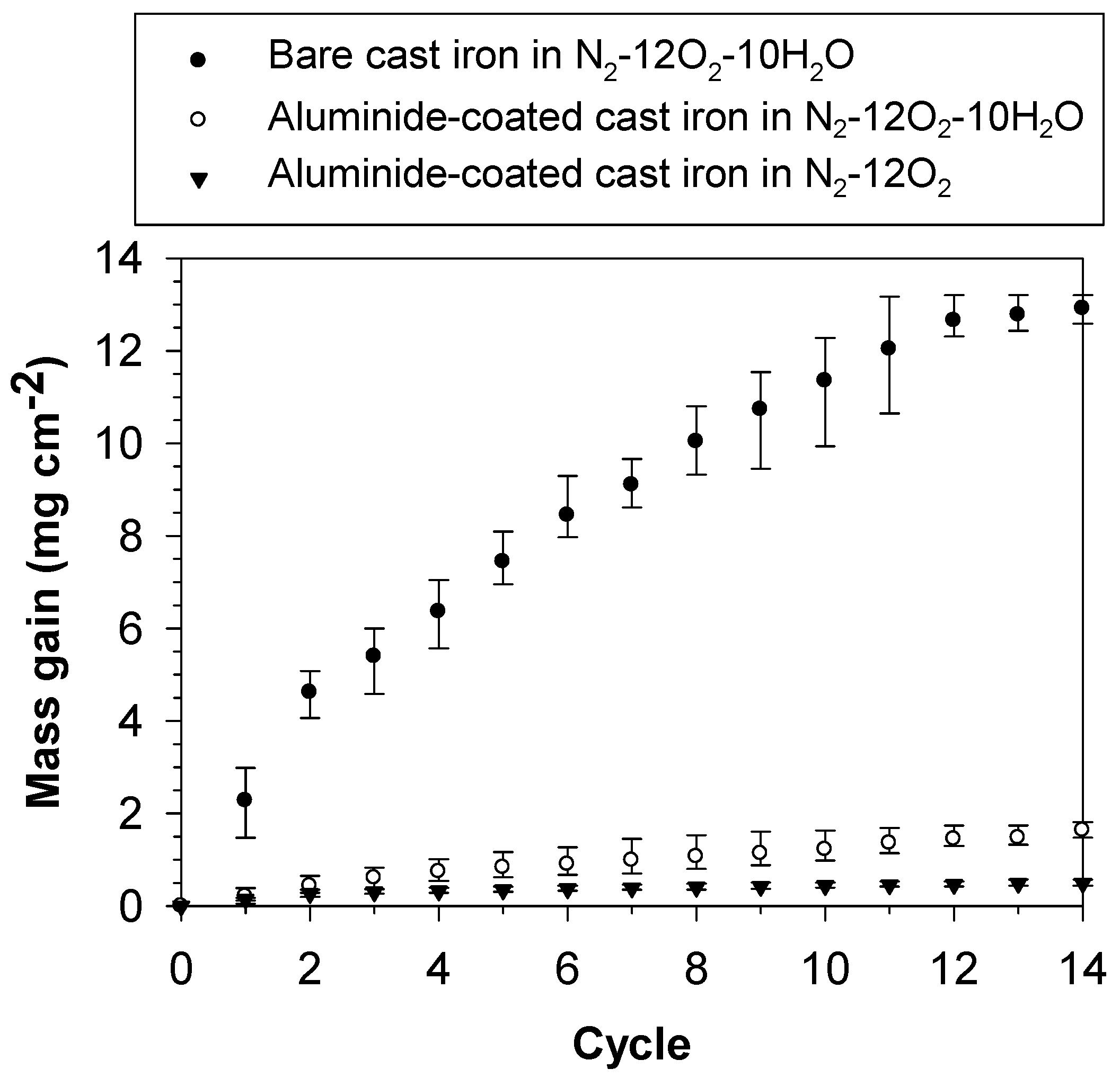
  • The cyclic oxidation kinetics of the bare cast iron in N2–12O2–10H2O and the aluminide-coated cast iron in N2–12O2–10H2O and N2–12O2 at 850 °C were parabolic, indicating that their oxidation rates reduce when the period of oxidation is longer. Furthermore, aluminising can reduce the oxidation rate of the studied cast iron in both dry and humidified atmospheres.
  • The presence of water vapour in the atmosphere increased the oxidation rate of the aluminide-coated cast iron and helped thicken the aluminide layer. The higher hardness value of the coated sample oxidised in humidified atmosphere was also observed. This indicated the possible dissolution of hydrogen in the aluminide layer, which related to the enhanced oxidation rate and the thickening of the aluminide layer.

Author Contributions

Conceptualisation, S.C.-a.; methodology, S.C.-a.; validation, S.C.-a.; formal analysis, P.K., M.H.S.B., and S.C.-a.; investigation, P.K.; resources, S.C.-a.; data curation, P.K.; writing—original draft preparation, P.K. and S.C.-a.; writing—review and editing, M.H.S.B., W.C.-a., and S.C.-a.; supervision, S.C.-a.; project administration, S.C.-a.; funding acquisition, S.C.-a. All authors have read and agreed to the published version of the manuscript.

Funding

This research was funded by King Mongkut’s University of Technology North Bangkok, Grant numbers KMUTNB-ART-60-089 and KMUTNB-Post-62-07.

Conflicts of Interest

The authors declare no conflicts of interest.

References

  1. Tholence, F.; Norell, M. High Temperature Corrosion of Cast Alloys in Exhaust Environments I-Ductile Cast Irons. Oxid. Met. 2007, 69, 13–36. [Google Scholar] [CrossRef]
  2. Brady, M.P.; Muralidharan, G.; Leonard, D.N.; Haynes, J.A.; Weldon, R.G.; England, R.D. Long-term oxidation of candidate cast iron and stainless steel exhaust system alloys from 650 to 800 °C in air with water vapour. Oxid. Met. 2014, 82, 359–381. [Google Scholar] [CrossRef]
  3. Pedrazzini, S.; Kiseeva, K.; Escoube, R.; Gardner, H.M.; Douglas, J.O.; Radecka, A.; Mignanelli, P.M.; Hughes, G.M.; Chapman, G.; Edmondson, P.D.; et al. In-Service Oxidation and Microstructural Evolution of a Nickel Superalloy in a Formula 1 Car Exhaust. Oxid. Met. 2017, 89, 375–394. [Google Scholar] [CrossRef] [Green Version]
  4. Yamagato, H. The Science and Technology of Materials in Automotive Engines; Woodhead Publishing Limited: Cambridge, UK, 2005; pp. 248–260. [Google Scholar]
  5. Al-Arkawazi, S.A.F. Analyzing and predicting the relation between air–fuel ratio (AFR), lambda (λ) and the exhaust emissions percentages and values of gasoline-fueled vehicles using versatile and portable emissions measurement system tool. SN Appl. Sci. 2019, 1, 1370. [Google Scholar] [CrossRef] [Green Version]
  6. Dawi, K.; Favergeon, J.; Moulin, G. High Temperature Corrosion of the Si-Mo Cast Iron in Exhaust Atmosphere. Mater. Sci. Forum 2008, 595, 743–751. [Google Scholar] [CrossRef]
  7. Lin, M.-B.; Wang, C.-J.; Volinsky, A.A. High Temperature Oxidation Behavior of Flake and Spheroidal Graphite Cast Irons. Oxid. Met. 2011, 76, 161–168. [Google Scholar] [CrossRef]
  8. Wang, X.; Fan, Y.; Zhao, X.; Du, A.; Ma, R.; Cao, X. Process and High-Temperature Oxidation Resistance of Pack-Aluminized Layers on Cast Iron. Mettals 2019, 9, 648. [Google Scholar] [CrossRef] [Green Version]
  9. Ekström, M.; Szakálos, P.; Jonsson, S. Influence of Cr and Ni on High-Temperature Corrosion Behavior of Ferritic Ductile Cast Iron in Air and Exhaust Gases. Oxid. Met. 2013, 80, 455–466. [Google Scholar] [CrossRef]
  10. Ekström, M. Oxidation and Corrosion Fatigue Aspects of Cast Exhaust Manifold. Ph.D. Thesis, KTH Royal Institute of Technology, Stockholm, Sweden, 2015. [Google Scholar]
  11. Ebel, A.; Brou, S.Y.; Malard, B.; Lacaze, J.; Monceau, D.; Vaissière, L. High-Temperature Oxidation of a High Silicon SiMo Spheroidal Cast Iron in Air with In Situ Change in H2O Content. Mater. Sci. Forum 2018, 925, 353–360. [Google Scholar] [CrossRef] [Green Version]
  12. Tholence, F.; Norell, M. High Temperature Corrosion of Cast Alloys in Exhaust Environments. II—Cast Stainless Steels. Oxid. Met. 2007, 69, 37–62. [Google Scholar] [CrossRef]
  13. Inoue, Y.; Kikuchi, M. Present and future trends of stainless steel for automotive exhaust system. High-Temperature 2003, 950, 750. [Google Scholar]
  14. Zheng, L.; Peng, X.; Wang, F. Comparison of the dry and wet oxidation at 900 °C of η-Fe2Al5 and δ-Ni2Al3 coatings. Corros. Sci. 2011, 53, 597–603. [Google Scholar] [CrossRef]
  15. Agüero, A.; Baraibar, I.; González, V.; Muelas, R.; Plana, D. Corrosion resistance of novel coatings on ferritic seels for oxycombustuin-supercritical steam boilers: Preliminary results. Oxid. Met. 2016, 85, 263–281. [Google Scholar] [CrossRef]
  16. Agüero, A.; Gutiérrez, M.; Muelas, R. Aluminum Solid-Solution Coating for High-Temperature Corrosion Protection. Oxid. Met. 2017, 88, 145–154. [Google Scholar] [CrossRef]
  17. Houngninou, C.; Chevalier, S.; Larpin, J. Synthesis and characterisation of pack cemented aluminide coatings on metals. Appl. Surf. Sci. 2004, 236, 256–269. [Google Scholar] [CrossRef]
  18. Mao, S.-W.; Huang, H.-L.; Gan, D. Microstructure and aluminized stainless steel 310 after annealing. Surf. Coat. Technol. 2010, 205, 533–539. [Google Scholar] [CrossRef]
  19. Shirvani, K.; Firouzi, S.; Rashidghamat, A. Microstructures and cyclic oxidation behaviour of Pt-free and low-Pt NiAl coatings on the Ni-base superalloy Rene-80. Corros. Sci. 2012, 55, 378–384. [Google Scholar] [CrossRef]
  20. Mollard, M.; Rannou, B.; Bouchaud, B.; Balmain, J.; Bonnet, G.; Pedraza, F. Comparative degradation of nickel aluminized by slurry and by pack cementation under isothermal conditions. Corros. Sci. 2013, 66, 118–124. [Google Scholar] [CrossRef]
  21. Dutta, R.S.; Banerjee, R.H.; Dey, G.K. An XPS Study with Depth Profiling for the Surface Oxide Layer Formed on Aluminides Produced on Superalloy 690 Substrates. Oxid. Met. 2017, 89, 699–711. [Google Scholar] [CrossRef]
  22. El-Helaly, M.; Elzomor, M.A.; Ahmed, M.H.; Youssef, A.O. Effect of Zirconium Addition on High-Temperature Cyclic Oxidation of Diffusion Chromo-Aluminized Ni-Base Superalloy. Oxid. Met. 2018, 91, 159–175. [Google Scholar] [CrossRef]
  23. Nowak, W.J.; Tomków, M.; Wierzba, P.; Gancarczyk, K.; Wierzba, B. The Role of Substrate Surface Roughness on in-Pack Aluminization Kinetics of Ni-Base Superalloy. J. Manuf. Mater. Process. 2020, 4, 15. [Google Scholar] [CrossRef] [Green Version]
  24. Tuck, C.; Odgers, M.; Sachs, K. The oxidation of iron at 950°C in oxygen/water vapour mixtures. Corros. Sci. 1969, 9, 271–285. [Google Scholar] [CrossRef]
  25. Wouters, Y.; Galerie, A.; Petit, J.-P. Thermal oxidation of titanium by water vapour. Solid State Ion. 1997, 104, 89–96. [Google Scholar] [CrossRef]
  26. Galerie, A.; Wouters, Y.; Caillet, M. The Kinetic Behaviour of Metals in Water Vapour at High Temperatures: Can General Rules Be Proposed? Mater. Sci. Forum 2001, 369, 231–238. [Google Scholar] [CrossRef]
  27. Saunders, S.; Monteiro, M.; Rizzo, F. The oxidation behaviour of metals and alloys at high temperatures in atmospheres containing water vapour: A review. Prog. Mater. Sci. 2008, 53, 775–837. [Google Scholar] [CrossRef]
  28. Young, D.J.; Zurek, J.; Singheiser, L.; Quadakkers, W.J. Temperature dependence of oxide scale formation on high-Cr ferritic steels in Ar–H2–H2O. Corros. Sci. 2011, 53, 2131–2141. [Google Scholar] [CrossRef]
  29. Chandra-ambhorn, S.; Ngamkham, K.; Jiratthanakul, N. Effects of Process Parameters on Mechanical Adhesion of Thermal Oxide Scales on Hot-Rolled Low Carbon Steels. Oxid. Met. 2013, 80, 61–72. [Google Scholar] [CrossRef]
  30. Chandra-ambhorn, S.; Nilsonthi, T.; Wouters, Y.; Galerie, A. Oxidation of simulated recycled steels with 0.23 and 1.03 wt.% Si in Ar–20%H2O at 900 °C. Corros. Sci. 2014, 87, 101–110. [Google Scholar] [CrossRef]
  31. Nguyen, T.D.; Zhang, J.; Young, D.J. Water vapor effect of Fe–Cr and Fe–Cr–Ni alloys containing cerium and manganese in CO2 gas at 818 °C. Corros. Sci. 2014, 89, 220–235. [Google Scholar] [CrossRef]
  32. Zhang, Y.; Pint, B.A.; Haynes, J.A.; Tortorelli, P.F. The Effect of Water Vapor on the Oxidation Behavior of CVD Iron-Aluminide Coatings. Oxid. Met. 2004, 62, 103–120. [Google Scholar] [CrossRef]
  33. Wang, C.J.; Badaruddin, M.; Badaruddin, M. The dependence of high temperature resistance of aluminized steel exposed to water-vapour oxidation. Surf. Coat. Technol. 2010, 205, 1200–1205. [Google Scholar] [CrossRef]
  34. Xing, L.; Zheng, Y.; Cui, L.; Sun, M.; Shao, M.; Lu, G. Influence of water vapor on the oxidation behavior of aluminized coatings under low oxygen partial pressure. Corros. Sci. 2011, 53, 3978–3982. [Google Scholar] [CrossRef]
  35. Callister, W.D.; Rethwisch, D.G. Fundamentals of Materials Science and Engineering: An Integrated Approach, 3rd ed.; John Wiley & Sons: Hoboken, NJ, USA, 2012; p. 552. [Google Scholar]
  36. Barin, I. Thermochemical Data of Pure Substances; Wiley: Hoboken, NJ, USA, 1995; p. 795. [Google Scholar]
  37. Young, D.J. High Temperature Oxidation and Corrosion of Metals; Elsevier: Amsterdam, The Netherlands, 2008; pp. 16–18. [Google Scholar]
  38. Kofstad, P. High Temperature Corrosion; Elsevier Applied Science: Essex, UK, 1988; pp. 17–18. [Google Scholar]
  39. Zhang, Z.; Gesmundo, F.; Hou, P.; Niu, Y. Criteria for the formation of protective Al2O3 scales on Fe–Al and Fe–Cr–Al alloys. Corros. Sci. 2006, 48, 741–765. [Google Scholar] [CrossRef]
  40. Yang, X.; Peng, X.; Wang, F. Effect of annealing treatment on the oxidation of an electrodeposited alumina-forming Ni–Al nanocomposite. Corros. Sci. 2008, 50, 3227–3232. [Google Scholar] [CrossRef]
  41. Badini, C.; Laurella, F. Oxidation of FeCrAl alloy: Influence of temperature and atmosphere on scale growth rate and mechanism. Surf. Coat. Technol. 2001, 135, 291–298. [Google Scholar] [CrossRef]
  42. Cueff, R.; Buscail, H.; Caudron, E.; Issartel, C.; Riffard, F. Oxidation of alumina formers at 1173 K: Effect of yttrium ion implantation and yttrium allying addition. Corros. Sci. 2003, 45, 1815–1831. [Google Scholar] [CrossRef]
  43. Cueff, R.; Buscail, H.; Caudron, E.; Riffard, F.; Issartel, C.; El Messki, S. Effect of reactive element oxide coating on the high temperature oxidation behaviour of FeCrAl alloys. App. Surf. Sci. 2004, 229, 233–241. [Google Scholar] [CrossRef]
  44. Maréchal, L.; Lesage, B.; Huntz, A.M.; Molins, R. Oxidation behaviour of ODS Fe–Cr–Al alloys: Aluminium depletion and life time. Oxid. Met. 2003, 60, 1–27. [Google Scholar] [CrossRef]
  45. Chandra-ambhorn, S.; Jutilarptavorn, A.; Rojhirunsakool, T. High temperature oxidation of irons without and with 0.06 wt% Sn in dry and humidified oxygen. Corros. Sci. 2019, 148, 355–365. [Google Scholar] [CrossRef]
  46. Chandra-ambhorn, S.; Thublaor, T.; Pascal, C. CHAPTER 1 Thermodynamics and Kinetics of the High Temperature Oxidation of Stainless Steels. Solid State Phenom. 2020, 300, 1–24. [Google Scholar] [CrossRef] [Green Version]
  47. Sarrazin, P.; Galerie, A.; Fouletier, J. Les Mécanismes de la Corrosion Sèche: Une Approach Cinétique; EDS Sciences: Les Ulis, France, 2000; pp. 8–11. [Google Scholar]
  48. Kubaschewski, O.; Evans, E.L.; Alcock, C.B. Metallurgical Thermochemistry; Pergamon Press: Oxford, UK, 1951; pp. 336–343. [Google Scholar]
  49. Ahtoy, E. Effect of Alloying Elements (Si, P, Al, B) on Low Carbon Steel Oxidation in Process at High Temperatures: Mechanism and Modeling. Ph.D. Thesis, Institut Polytechnique de Grenoble, Grenoble, France, 2010. [Google Scholar]
  50. Nishimoto, T.; Honda, K.; Kondo, Y.; Uemara, K. Effects of Si content on the oxidation behaviour of Fe-Si alloys in air. Mater. Sci. Forum 2011, 696, 126–131. [Google Scholar] [CrossRef]
  51. Fukumoto, M.; Maeda, S.; Hayashi, S.; Narita, T. Effect of Water Vapor on the Oxidation Behavior of Fe–1.5Si in Air at 1073 and 1273 K. Oxid. Met. 2001, 55, 401–422. [Google Scholar] [CrossRef]
  52. Maitra, T.; Gupta, S. Intermetallic compound formation in Fe–Al–Si ternary system: Part II. Mater. Charact. 2002, 49, 293–311. [Google Scholar] [CrossRef]
  53. Dutta, M.; Singh, S.B. Effect of strip temperature on the formation of an Fe2Al5 inhibition layer during hot-dip galvanizing. Scr. Mater. 2009, 60, 643–646. [Google Scholar] [CrossRef]
  54. Wang, C.-J.; Chen, S.-M. The high-temperature oxidation behavior of hot-dipping Al–Si coating on low carbon steel. Surf. Coat. Technol. 2006, 200, 6601–6605. [Google Scholar] [CrossRef]
  55. Wang, X.H.; Zhou, Y.C. Oxidation behavior of Ti3AlC2 at 1000–1400 °C in air. Corros. Sci. 2003, 45, 891–907. [Google Scholar] [CrossRef]
  56. Lin, Z.; Li, M.; Wang, J.; Zhou, Y. Influence of water vapor on the oxidation behavior of Ti3AlC2 and Ti2AlC. Scr. Mater. 2008, 58, 29–32. [Google Scholar] [CrossRef]
  57. Hou, P.Y. Oxidation of metals and alloys, In Shreir’s Corrosion Volume I Basic Concepts, High Temperature Corrosion; Cottis, R.A., Graham, M., Lindsay, R., Lyon, S., Richardson, T., Scantlebury, D., Stott, H., Eds.; Elsevier: Amsterdam, The Netherlands, 2010; pp. 195–239. [Google Scholar]
  58. Djukic, M.B.; Zeravcic, V.S.; Bakic, G.; Sedmak, A.; Rajicic, B. Hydrogen Embrittlement of Low Carbon Structural Steel. Procedia Mater. Sci. 2014, 3, 1167–1172. [Google Scholar] [CrossRef] [Green Version]
  59. Stępień, K.; Kupka, M. Effect of hydrogen on room-temperature hardness of B2 FeAl alloys. Scr. Mater. 2008, 59, 999–1001. [Google Scholar] [CrossRef]
  60. Kirchheim, R. Reducing grain boundary, dislocation line and vacancy formation energies by solute segregation. I. theoretical background. Acta Mater. 2007, 55, 5129–5138. [Google Scholar] [CrossRef]
  61. Cizek, J.; Lukáč, F.; Prochazka, I.; Vlček, M.; Jirásková, Y.; Švec, P.; Janičkovič, D. Positive effect of hydrogen-induced vacancies on mechanical alloying of Fe and Al. J. Alloy. Compd. 2015, 629, 22–26. [Google Scholar] [CrossRef]
  62. Fähnle, M.; Mayer, J.; Meyer, B. Theory of atomic defects and diffusion in ordered compounds, and application to B2-FeAl. Intermetallics 1999, 7, 315–323. [Google Scholar] [CrossRef]
Figure 1. SEM cross-section of the ductile cast iron used in the study.
Coatings 10 00705 g001
Figure 2. Mass gain of bare and aluminide-coated cast irons during cyclic oxidation at 850 °C.
Coatings 10 00705 g002
Figure 3. SEM cross-section of the bare cast iron after cyclic oxidation at 850 °C in N2–12O2–10H2O for 14 cycles.
Coatings 10 00705 g003
Figure 4. XRD pattern of the bare cast iron after cyclic oxidation at 850 °C in N2–12O2–10H for 14 cycles.
Coatings 10 00705 g004
Figure 5. Raman patterns of the bare cast iron after cyclic oxidation at 850 °C in N2–12O2–10H2O for 14 cycles.
Coatings 10 00705 g005
Figure 6. SEM cross-sections of the aluminide-coated cast iron (a) before oxidation, (b) after cyclic oxidation in N2–12O2 at 850 °C for 14 cycles, and (c) after cyclic oxidation in N2–12O2–10H2O at 850 °C for 14 cycles.
Coatings 10 00705 g006
Figure 7. XRD patterns of the aluminide-coated cast iron (a) before oxidation, (b) after cyclic oxidation in N2–12O2 at 850 °C for 14 cycles and (c) after cyclic oxidation in N2–12O2–10H2O at 850 °C for 14 cycles.
Coatings 10 00705 g007
Figure 8. Relationship between the square of mass gain and time for the cyclic oxidation at 850 °C of (a) the bare cast iron in N2–12O2–10H2O and (b) the aluminide-coated cast irons in N2–12O2–10H2O and in N2–12O2.
Coatings 10 00705 g008aCoatings 10 00705 g008b
Figure 9. Equilibrium diagram of the formation of oxides relevant to the present work constructed using thermodynamic data from Kubaschewski and Evans [48].
Coatings 10 00705 g009
Figure 10. Gibbs free energies to form Fe–Al intermetallic compounds per one mole of Al at the standard state.
Coatings 10 00705 g010

