Article

Influence of the Silver Nanoparticles (AgNPs) Formation Conditions onto Titanium Dioxide (TiO2) Nanotubes Based Electrodes on Their Impedimetric Response

by
Marta Nycz
1,*,
Katarzyna Arkusz
1 and
Dorota Genowefa Pijanowska
2
1
Department of Biomedical Engineering, Faculty of Mechanical Engineering, University of Zielona Góra, Prof. Z. Szafrana 4, 54-516 Zielona Góra, Poland
2
Nałęcz Institute of Biocybernetics and Biomedical Engineering, Polish Academy of Sciences, Ks. Trojdena 4, 02-109 Warszawa, Poland
*
Author to whom correspondence should be addressed.
Nanomaterials 2019, 9(8), 1072; https://doi.org/10.3390/nano9081072
Submission received: 18 June 2019 / Revised: 17 July 2019 / Accepted: 24 July 2019 / Published: 25 July 2019

Abstract

:
This paper presents the comparison of the effects of three methods of production of silver spherical and near-spherical nanoparticles (AgNPs) on the titanium dioxide nanotubes (TNT) base: cyclic voltammetry, chronoamperometry, and sputter deposition. It also evaluates the influence of silver nanoparticles on the electrochemical properties of the developed electrodes. The novelty of this research was to fabricate regular AgNPs free of agglomerates uniformly distributed onto the TNT layer, which has not been accomplished with previous attempts. The applied methods do not require stabilizing and reducing reagents. The extensive electrochemical characteristic of AgNP/TNT was performed by open circuit potential and electrochemical impedance spectroscopy methods. For AgNPs/TNT obtained by each method, the impedance module of these electrodes was up to 50% lower when compared to TNT, which means that AgNPs enabled more efficient electron transfer due to the effective area increase. In addition, the presence of nanoparticles increases the corrosion resistance of the prepared electrodes. These substrates can be used as electrochemical sensors due to their high electrical conductivity, and also as implants due to the antibacterial properties of both the TNT and AgNPs.

Graphical Abstract

1. Introduction

In recent years, the rapid development of sensors for biomedical applications has been observed because of the urgent need for non-standard diagnostic methods for fast and effective diagnosis of various disease entities. The sensor platform may be composed of many materials, the most frequently used being carbon [1,2,3] or silica-based compounds [4], polymers [5,6], or gold [7]. Platforms for sensors in the form of composites with two or more compounds [8] are becoming more and more popular. The main aim of using this kind of platform is to increase the sensitivity. Metal oxides and metallic nanostructures [9,10,11] are most widely applied. Among them, particular attention is paid to titanium dioxide nanotubes (TNT), which are characterized by high surface area, biocompatibility, good electrical conductivity, good adsorption properties, thermal and chemical stability, ease, and low production costs [12]. Improvement of the sensor sensitivity is obtained by the doping of metal nanoparticles, mainly gold nanoparticles (AuNPs) [13]. Silver nanoparticles (AgNPs) seem to be an alternative to these compounds. Its advantages are: ease and low cost of production, ease of binding with proteins in reaction with thiol group (–SH), and the best electrical conductivity among metals, so AgNPs may facilitate more efficient electron transfer than AuNPS. These properties make the AgNPs the most promising compound to be applied in electrochemical sensors [14,15,16,17]. However, the application of the AgNPs/TNT platform in sensing is rarely described [18,19]. At present, to the best of the authors’ knowledge, there are no publications reporting results on electrochemical characterization of the electrodes containing silver nanoparticles on titanium dioxide nanotubes. Most frequently, the characteristics of these platforms is limited only to evaluation of its photocatalytic and antimicrobial properties [20,21,22,23].
Besides traditional methods of silver nanoparticles production like chemical reduction of silver salts [24,25] using various (often expensive and toxic) reagents, new methods have been developed in recent years. The AgNPs have been produced by electrochemical methods [26], laser synthesis [27], sputter deposition [28], microwave irradiation [29], sonochemical synthesis [30] and photoreduction [31]. The methods of depositing AgNPs on TNT, which do not require the use of additional agents, are electrodeposition [32], i.e. potentiostatic [33,34] and galvanostatic [34] polarization, pulse method [35]. Similar results are obtained using sputtering [36]. However, the results obtained in previous studies [32,33] are not satisfactory due to the large number of agglomerates in the prepared substrates, or do not contain electrochemical analyses of these substrates [34,35,36].
The aim of this study was to compare the effects of three methods of silver spherical and near-spherical nanoparticles production on the titanium dioxide nanotubes base: cyclic voltammetry, chronoamperometry and sputtering, as well as to assess the influence of silver nanoparticles on the electrochemical properties of the developed electrodes. In the case of cyclic voltammetry, the variable parameter was the number of cycles, in the case of chronoamperometry and sputtering deposition time, so the influence of these parameters on the formation of agglomerates and the electrochemical characteristics of the samples were examined. For reference, an electrochemical study of TNT and TNT with a micro silver layer was also performed.

2. Materials and Methods

2.1. Materials

Titanium foil (purity 99.7%), ethylene glycol (assay 99.8%), ammonium fluoride (purity ≥98%), phosphate buffered saline (0.01 M PBS, 0.0027 M potassium chloride and 0.137 M sodium chloride pH 7.4) were purchased from Sigma-Aldrich (St. Louis, MO, USA). Silver nitrate (AgNO3, analytical grade) was purchased from Stanlab (Lublin, Poland). All solutions were prepared from Milli-Q water.

2.2. TiO2 Nanotubes Fabrication

The titanium foil was sonicated in acetone, distilled water and dried under nitrogen atmosphere. The TiO2 nanotube layers were prepared by electrochemical anodization of titanium foils using Autolab PGSTAT302N (Metrohm, Herisau, Switzerland) at 17 V for 3750 s. Ethylene glycol (85% wt.) with ammonium fluoride (0.65% wt.) were used as the anodizing electrolyte. Scanning electron microscopy (FESEM, JEOL JSM-7600F, Tokyo, Japan) and energy-dispersive X-ray spectroscopy (EDS, INCA, Oxford Instruments, Oxford, UK) were used to investigate the surface morphology and chemical composition.

2.3. Thermal Modification

TNT layers were annealed in the AMP furnace (AMP, Zielona Góra, PL) in argon atmosphere at 450 °C for 2 h with the heating and cooling rate of 6 °C min−1. Annealing was performed to convert the as-formed (amorphous) structure of the nanotubes into the crystalline structure of anatase and rutile, which results in an increase in the conductivity of the TNT.

2.4. Modification of TNT with Silver Nanoparticles

2.4.1. Cyclic Voltammetry Method (CV)

Deposition of AgNPs on TNT was carried out in 1 mM solution of AgNO3 in the potential range of −1.25 to −0.7 V in the three-electrode configuration with titanium dioxide nanotubular layer on the titanium foil as the working electrode, silver chloride electrode (EAg/AgCl = 0.222 V vs. Standard Hydrogen Electrode, SHE) by Metrohm as the reference electrode, and platinum mesh as the auxiliary electrode, with the scan rate of 0.05 V s−1 and a number of cycles in the range of 5–30. After deposition, the surface of the working electrode was washed with distilled water and dried under a nitrogen atmosphere. The samples will be hereinafter called x cycles_AgNPs/TNT, where x stands for the number of cycles.
In addition, to investigate the effect of silver nanoparticles on electrochemical characterization of TNT layers, TNT with a micro silver layer, hereinafter referred to as Ag/TNT, was used to compare their performance. For this purpose, the micro silver layer was produced by cyclic voltammetry in 50 mM solution of AgNO3 in the potential range −1.25 to −0.7 V with the scan rate of 0.05 V s−1 for 25 cycles.

2.4.2. Chronoamperometry Method (CA)

Deposition of AgNPs on TNT was carried out in 1 mM solution of AgNO3 with constant potential of −1.2 V in the three-electrode system described in 2.4.1., during 60–300 s. After deposition, the surface of the working electrode was washed with distilled water and dried under nitrogen atmosphere. The samples are hereinafter referred to as x chrono_AgNPs/TNT, where x stands for the time of deposition.

2.4.3. Sputter Deposition (SD)

For the deposition of AgNPs a sputter coater (Quorum Q150T ES, Quorum Technologies, Laughton, UK) equipped with a silver target (70-AG5710 Silver Target 99.97% pure, Micro to Nano V.O.F., Haarlem, Netherlands) were used to prepare a set of samples with different AgNPs loadings, which depends on the sputtering time in the range of 10–60 s at 50 mA. The samples will be hereinafter referred to as x target_AgNPs/TNT, where x stands for the time of sputtering.
Table 1 presents the summary of the naming of the performed electrodes.

2.5. Electrochemical Measurements

The open circuit potential (OCP) tests and electrochemical impedance spectroscopy (EIS) scans were recorded using a standard three-electrode configuration with TNT or AgNPs/TNT platforms as the working electrode, standard silver chloride electrode (EAg/AgCl = 0.222 V vs. SHE) by Metrohm as the reference electrode, and the platinum mesh as auxiliary electrode.
OCP measurements were carried out at room temperature (25 ± 2 °C) for 1800 s. EIS spectra were performed over a frequency range of 105–0.1 Hz with a signal amplitude of 10 mV. All experiments were performed in PBS solution (0.01 M, 20 mL, pH 7.4).
All measurements were repeated three times (for three samples n = 3) using the potentiostat/galvanostat model PGSTAT 302N from Autolab (Metrohm).

3. Results and Discussion

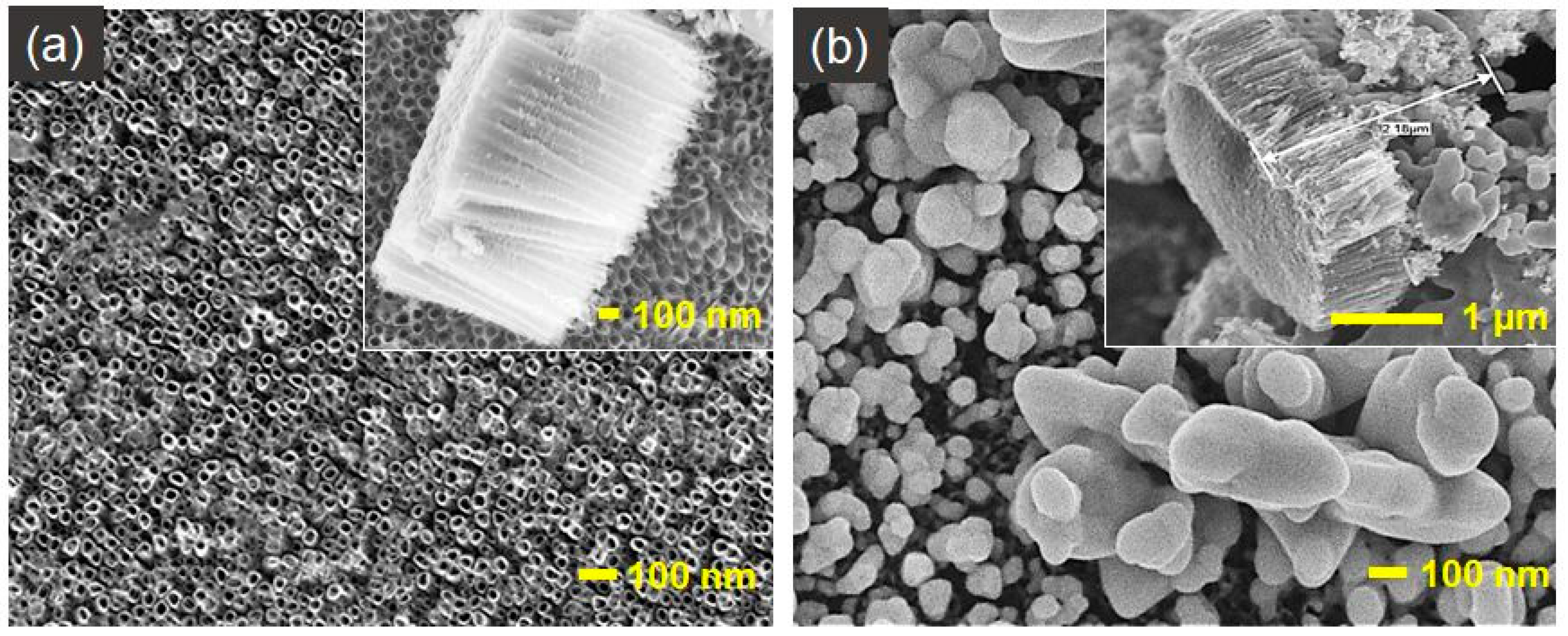
3.1. Characterization of Reference Platforms: TNT and Ag/TNT

SEM images of TNT (Figure 1a) show opened from the top, closed at the bottom, and vertically oriented regular nanotubes with 50 ± 5 nm outer diameter and 1000 ± 100 nm in length completely covering the titanium foil. No damage on the TNT layers after annealing at 450 °C for 2 h was observed. Figure 1b presents an irregular silver layer with an uneven height in which silver completely closes the nanotubular morphology of TNT (63.18 ± 8.60 % wt. of silver).
As a result of thermal treatment, the amorphous structure of the TiO2 (originally present in nanotube structures) changes into a crystalline form of rutile and/or anatase. The most important advantage of annealing is that it causes the formation of oxygen vacancies, which results in improved TNT conductivity, and thus facilitates the transfer of charge that is attributed to the conversion of Ti4+ to Ti3+ [37,38,39,40]. The crystalline phases indicate also more corrosion resistance than the amorphous phase [38]. Studies show that annealing in argon generates more oxygen vacancies in TiO2 than annealing in the air, oxygen, or nitrogen [41,42,43]. The TiO2 nanotubes annealed at 450 °C are characterized by the predominance of anatase in their structure [37,42,44], which is advantageous when using this substrate for biosensing, because anatase has a higher affinity for biomolecules than rutile [45]. On the other hand, Liang et al. [46] indicate that rutile structure may retard the formation of silver nanoparticles.

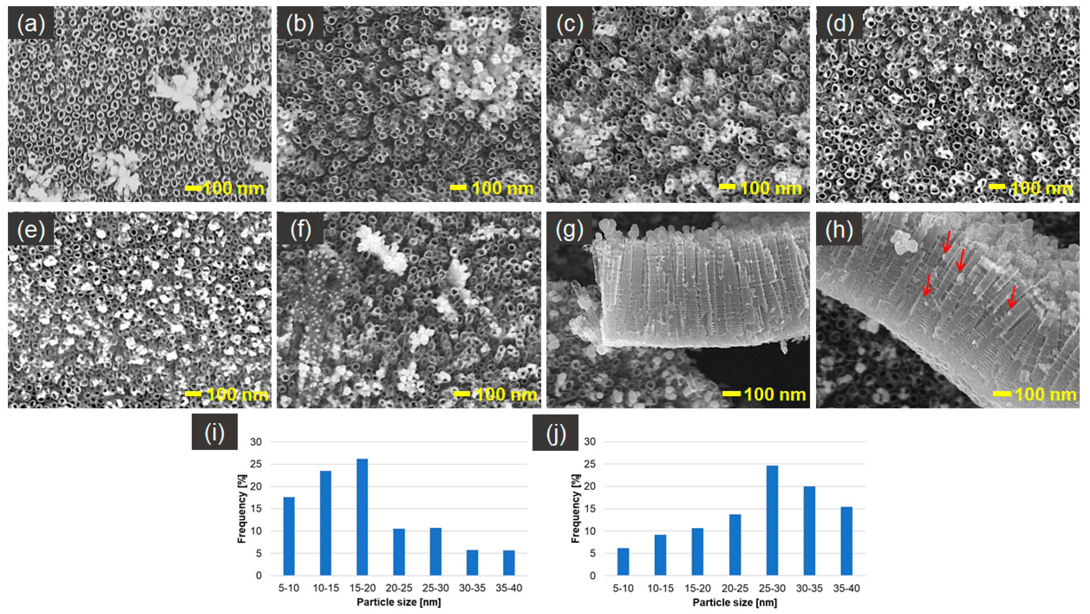
3.2. Characterisation of AgNPs/TNT Platforms with Silver Nanoparticles Obtained by Cyclic Voltammetry

Figure 2 presents SEM photographs of silver spherical and near-spherical nanoparticles on TNT platforms produced by cyclic voltammetry method, with the variable number of cycles. Only platforms after 20 and 25 cycles of CV of deposition do not contain silver nanoparticles agglomerates, and their size is between 5–40 nm. Distribution of the AgNPs after 20–25 cycles of CV (Figure 2d,e) of deposition is regular and well organized. Nanoparticles are concentrated mostly around nanotube edges, which can be caused by higher electric current density in those places [47]. The AgNPs, to a lesser extent, also fill the space between the nanotubes. Moreover, cross-sectional images of AgNPs/TNT (Figure 2g,h) show that some nanoparticles permeate into the nanotubes and embed in their inner walls. The mechanism of AgNPs formation consists of the nucleation of Ag metal at the initial stage. Ag metal has not completely evolved, with masses of the agglomerates on the top of the tubes. Afterwards, the Ag nuclei are created, and they become nucleation and growth sites for silver nanoparticles. After a time, nanoparticles can connect with each other and form into agglomerates [46]. For that reason samples 5–15 cycles_AgNPs/TNT (Figure 2b–d) contain agglomerates, which after 20–25 cycles of CV separate, resulting in the creation of homogeneously dispersed nanoparticles on TiO2 nanotubes substrate. The layer becomes supersaturated and agglomerates are created again with an increasing number of cycles of CV (around 30 cycles).
The particle size distribution histograms for the 20 and 25 cycles_AgNPs/TNT samples determined from the SEM images are shown in Figure 2i,j, respectively. From Figure 2i, it is clear that the frequency peak for 20 cycles_AgNPs/TNT electrode comes at approximately 15 nm–25 nm, and particles, whose sizes range from 5 nm to 30 nm, account for about 88% of the total particles observed. For 25 cycles_AgNPs/TNT sample the frequency peak comes at 25–30 nm, and particles, whose sizes range from 20 nm to 40 nm, account for about 75%.
Table 2 presents the results of measurements of the stationary potential of AgNPs/TNT platforms produced by cyclic voltammetry method and sizes of the obtained nanoparticles. Platforms that contain AgNPs and Ag/TNT are characterized by higher OCP value in comparison to TNT (−66 ± 14 mV). Electrodes 10–15 cycles_AgNPs/TNT and Ag/TNT structure are characterized by positive OCP value. It results from the occurrence of a higher number of unreduced silver ions in the structure rich in agglomerates.
Figure 3 shows that along with the increased number of cycles (up to 25) comes a linear growth (R2 = 0.991) of silver content, whereas at a later stage the silver content does not increase, probably due to layer saturation.
Figure 4a shows the Nyquist diagrams determined for AgNPs/TNT platforms differing in the number of cycles of silver nanoparticles deposition using cyclic voltammetry and for reference layers: TNT and Ag/TNT. The highest resistive character, which indicates the lower electrical conductivity, was observed for the TNT layer. On the other hand, the highest conductivity values were observed for AgNPs/TNT platform after 25 cycles of CV and for Ag/TNT (2919 ± 451 Ω). Both substrates are characterized by a similar value of impedance module, but the AgNPs/TNT platform (25 cycles) contains approximately 56% of silver weight less than Ag/TNT, which indicates that the elaborated electrode has a large surface area. Achieved results, according to results described in literature [48,49,50,51,52,53,54,55] in which the addition of silver nanoparticles is deposited onto various substrates, caused a decrease in the impedance module of the created sensor, in some cases even more than by 50%. Structures formed after 10, 15, and 30 cycles of deposition were characterized by lower conductivity, possibly due to the presence of agglomerates, which impede the electron transfer along a tubular structure. The phase angle values presented in Bode plots (Figure 4b) recorded in the lowest frequencies (0.1 Hz) in the range 79° to 71° are related to the porosity of the sample surface. The lowest porosity value of the phase angle was observed for the Ag/TNT.

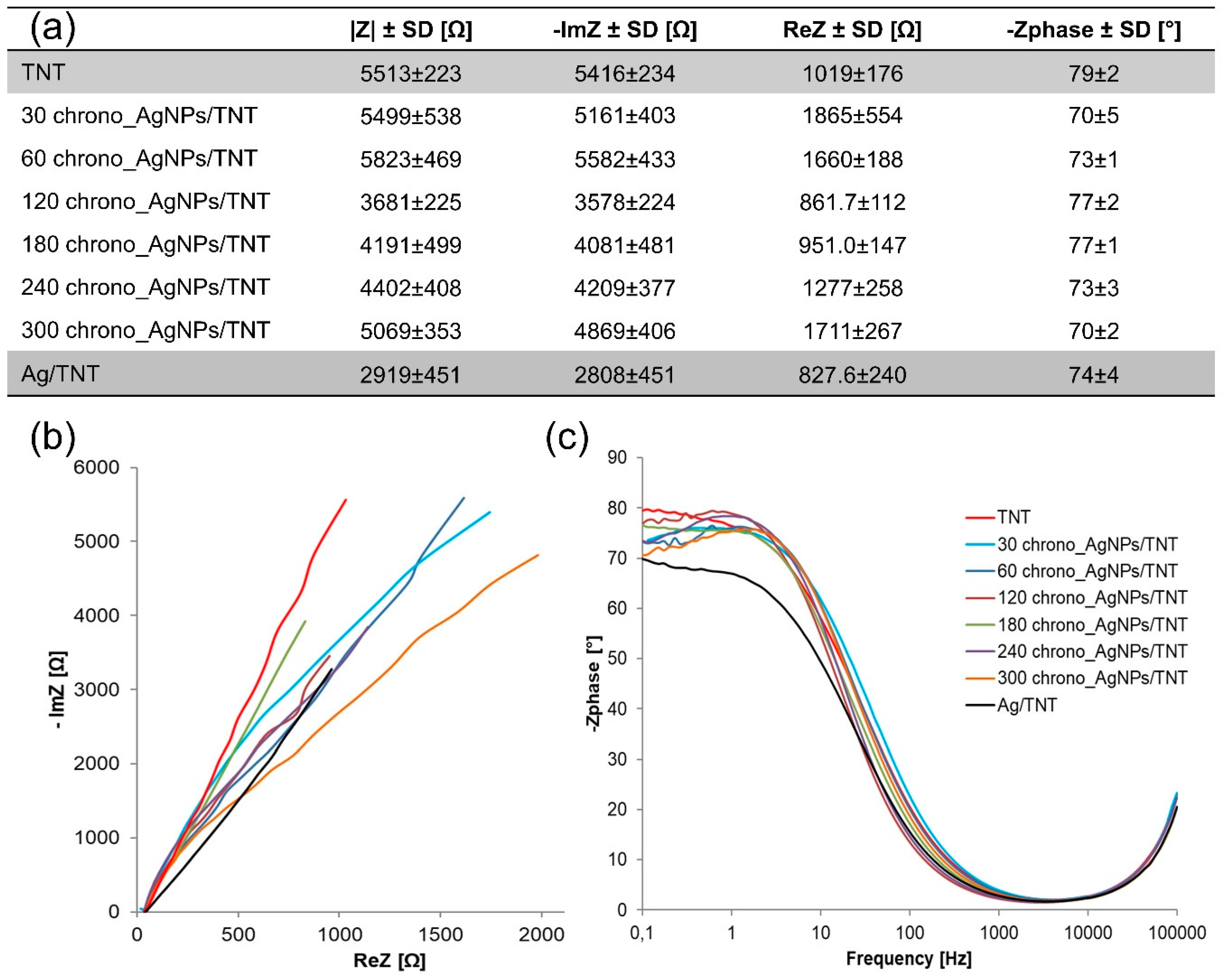
3.3. Characterization of AgNPs/TNT Platforms in which Silver Nanoparticles Were Obtained by Chronoamperometry

Figure 5 presents SEM photographs of silver spherical and near-spherical nanoparticles on TNT platforms produced by the chronoamperometry method where the duration of the process was a variable. Only platforms 60–180 chrono_AgNPs/TNT do not contain agglomerates and the distribution of AgNPs is regular and almost uniform, and the majority of them are present in the upper part of nanotubes, similar to the platforms produced by the CV method. The mechanism of nanoparticles formation corresponds to the one described in the previous subchapter.
The particle size distribution histograms for the 60–180_AgNPs/TNT samples determined from the SEM images are shown in Figure 5g–i. From Figure 5g, it is clear that the frequency peak for 60 and 120 chrono_AgNPs/TNT electrodes came at 10 nm–15 nm (Figure 5h) for 180 chrono_AgNPs/TNT at 15–20 nm (Figure 5i). For 25 cycles_AgNPs/TNT sample the frequency peak comes at 25–30 nm. As the deposition time increased, the spread of the obtained nanoparticles sizes increased.
Table 3 presents the results of measurements of the stationary potential of AgNPs/TNT platforms produced by the chronoamperometry method and sizes of the obtained nanoparticles. Platforms that contain Ag are characterized by higher OCP value in comparison to TNT without nanoparticles. AgNPs/TNT obtained after 60 and 120 s of deposition are characterized by positive OCP value. A similar tendency has been observed in the voltammetric method of nanoparticles production. Initially, the nanoparticles were not stable and their surface area was very easily oxidized, but the longer deposition time indicated the greater nanoparticles’ stability, which results in lower OCP value (despite higher silver content in the structure in comparison to AgNPs/TNT produced after 60 and 120 s). Figure 6 shows that along with an increase in the process duration, there comes exponential growth of the silver content (R2 = 0.9754) in the obtained substrates.
Figure 7 shows the Nyquist diagrams determined for AgNPs/TNT platforms differing in time of silver nanoparticles deposition and for reference layers TNT and Ag/TNT. The addition of nanoparticles caused a decrease in the impedance module and thus improvement in electrical conductivity of the created platforms, which was connected to a large effective area facilitating the electron transfer [56]. The formation of agglomerates and plugging the nanotubes by nanoparticles has a negative effect on the structure conductivity, which is confirmed by research [57] showing that the highest impedance module is characteristic of the structures where the tubular structure is not blocked. The lowest impedance module is characteristic of the 120 chrono_AgNPs/TNT platform.

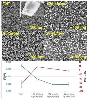
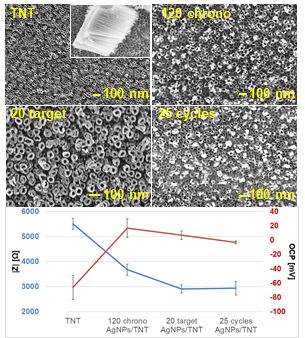
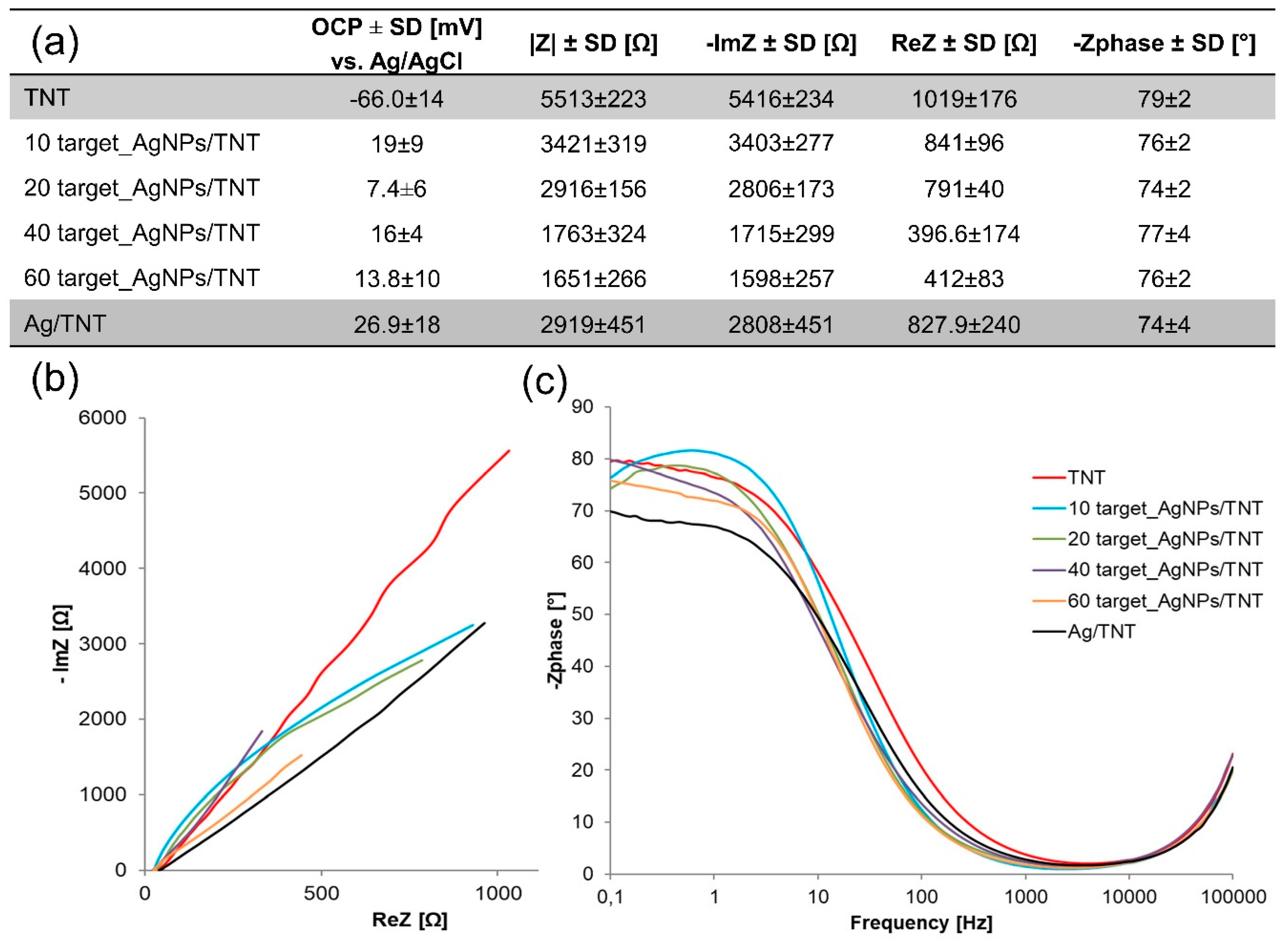
3.4. Characterisation of AgNPs/TNT Platforms in which Silver Nanoparticles Were Obtained by Sputter Deposition

Figure 8 presents SEM micrographs of AgNPs/TNT platforms produced by sputter deposition. Figure 8a,b show that the distribution of AgNPs is regular, well organized and focused on the edges of nanotubes. The AgNPs, to a lesser extent, fill the space between the nanotubes and also permeate into the nanotubes and embed in their inner walls (Figure 8e,f). The nanoparticles have a spherical and near-spherical shape, and after 20 seconds of sputtering, AgNPs are located around the ring of nanotubes and the formation of nanoclusters was observed. The amount of silver was so large that it resulted in a visible reduction of their diameter. Over time, this layer increased in thickness, completely closing the tubular morphology. These studies are in accordance with the results obtained by Roguska et al [36].
The particle size distribution histograms for the 10 and 20 target_AgNPs/TNT samples determined from the SEM images are shown in Figure 8g,h, respectively. The frequency peak for 10 target_AgNPs/TNT electrode comes at 20 nm–25 nm, and particles, whose sizes range from 10 nm to 25 nm, account for about 80% of the total particles observed. For the 20 target_AgNPs/TNT sample the frequency peak came at approximately 30–40 nm.
Figure 9 shows that along with the increase in process duration, there came exponential growth of the silver content (R2 = 0.9744) and a linear growth (R2 = 0.9992) of thickness of the silver layer in the obtained substrates.
The table in Figure 10 shows that adding silver to the structure caused an increase in the OCP values of created platforms. Figure 10a shows the Nyquist diagrams determined for AgNPs/TNT platforms differing in time of sputter deposition and for reference layers TNT and Ag/TNT. When the immersion time, and at the same time the silver weight content in the structure were increased, the impedance module was lowered, and for a sample after 60 s of sputtering it reached the value two times smaller than for Ag/TNT, but 60 target_AgNPs/TNT platform contained approximately 50% of silver weight less than the reference sample. It indicates that maintaining an open tubular structure is necessary for the efficient transport of electrons, which affects the conductivity of the platform. However, importantly, samples 40–60 target_AgNPs/TNT should be considered TNT platforms with silver nanoclusters, not with nanoparticles. The Bode plot (Figure 10b) shows that silver deposition reduces the phase angle of the AgNPs/TNT samples.
The greatest advantages of the sputter deposition and electrochemical production of nanoparticles are their ease and speed of implementation, as well as the possibility of controlling the process. Additionally applied methods do not require the stabilizing and reducing reagents.
Each of the methods of AgNPs formation allowed to produce platforms whose impedance module was similar to reference substrate Ag/TNT. In the case of CV, it was 25 cycles_AgNPs/TNT sample, for CA – 120 chrono_AgNPs/TNT, and for SD – 20_target_AgNPs/TNT. 40–60 target_AgNPs/TNT are characterized by an impedance module almost 50% lower than Ag/TNT; however, these samples should be considered TNT platforms with silver nanoclusters, not with nanoparticles. Substrates containing silver agglomerates generated by electroreduction methods block the nanotubes by reducing the electrochemically active surface area and, therefore, also reduce the conductivity of AgNPs/TNT. In the case of sputtering, the nanoparticles agglomerate around the rings of the nanotubes without clogging them, and therefore do not reduce the conductivity of the electrodes; the greater the content of silver in the structure, the higher its conductivity.
In comparison to an impedance module equal to 5513 ± 223 Ω for TNT, in the case of electroreduction and sputter deposition methods, its value was reduced by approximately 50%. It is worth noting, however, that the aforementioned structures contained respectively 7.54 ± 0.76 % wt. Ag (25 cycles of CV), 2.57 ± 0.18 % wt. Ag (120 seconds of CA) and 6.79 ± 1.70 % wt. Ag (20 seconds of SD), and in the case of Ag/TNT (63.18 ± 8.60 % wt. Ag) it was 8–21 times higher content, which only confirms significant surface development of the created electrodes.

4. Conclusions

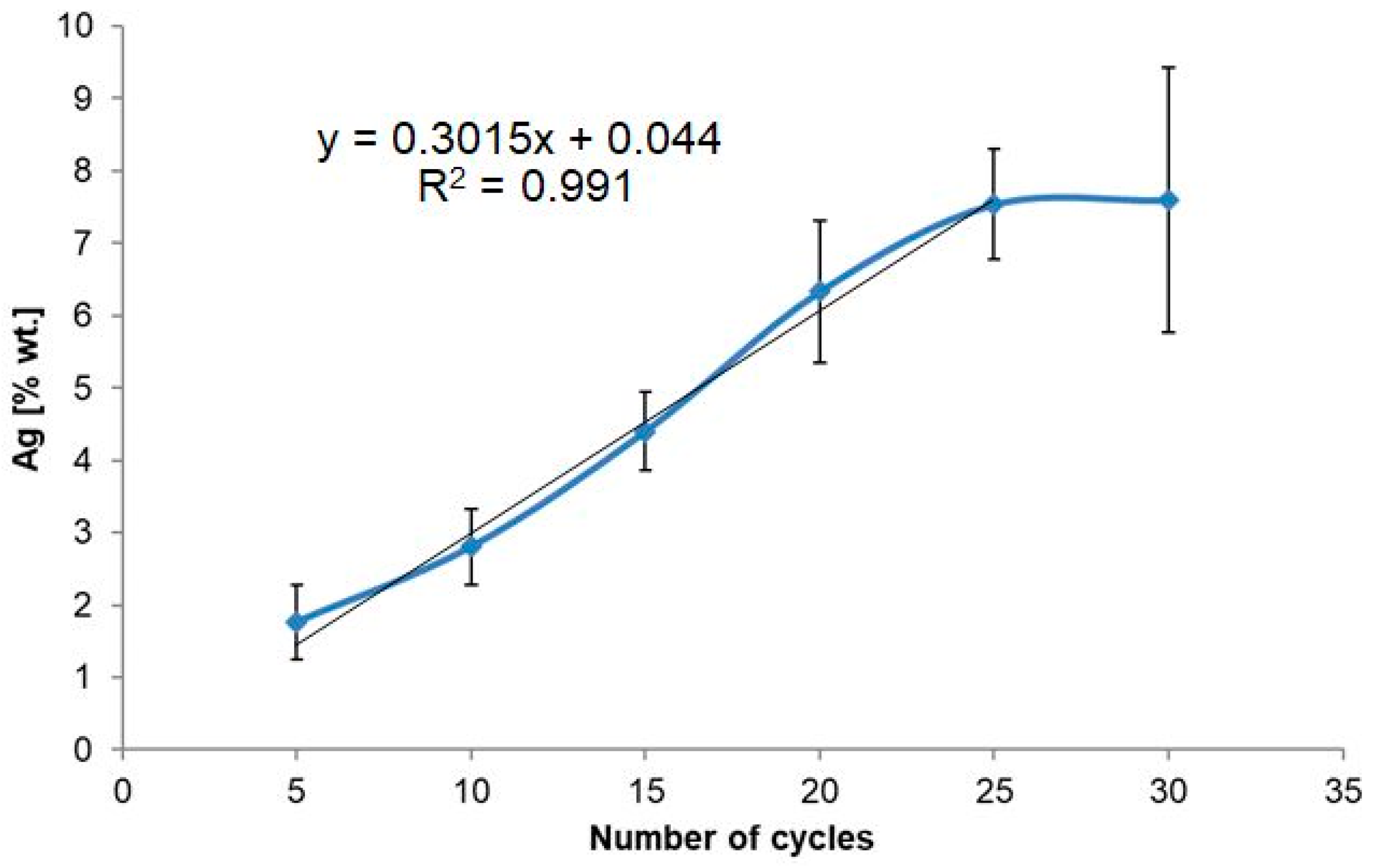
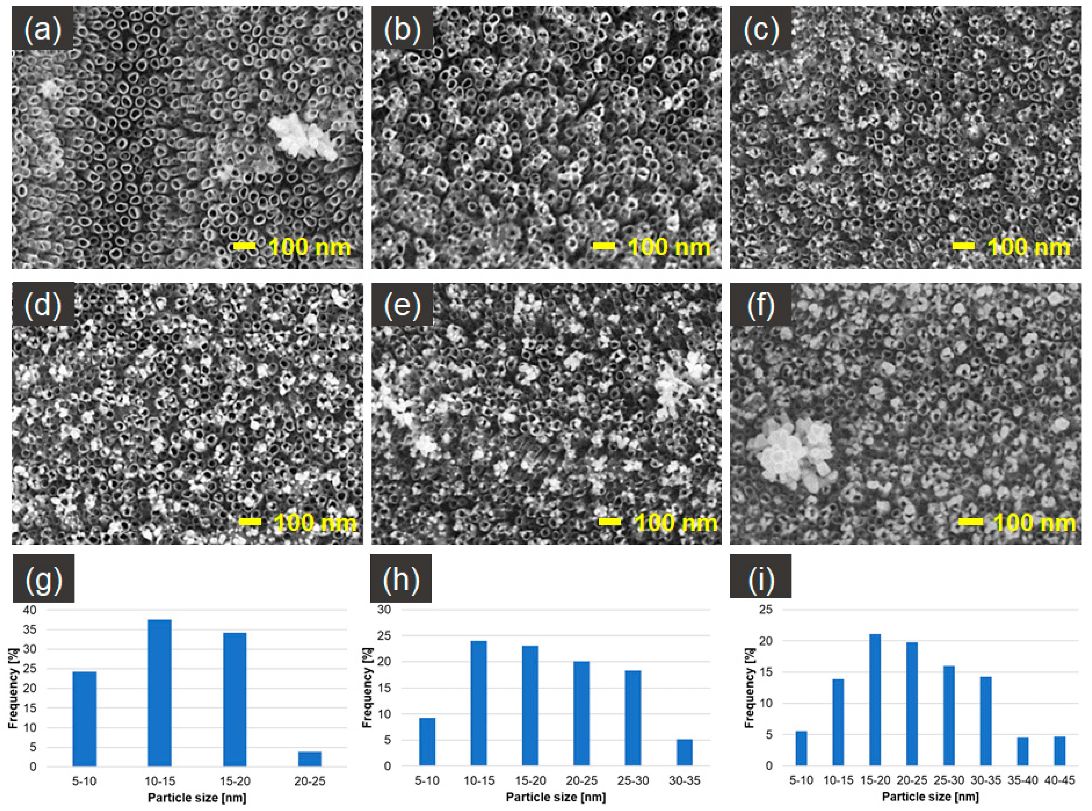
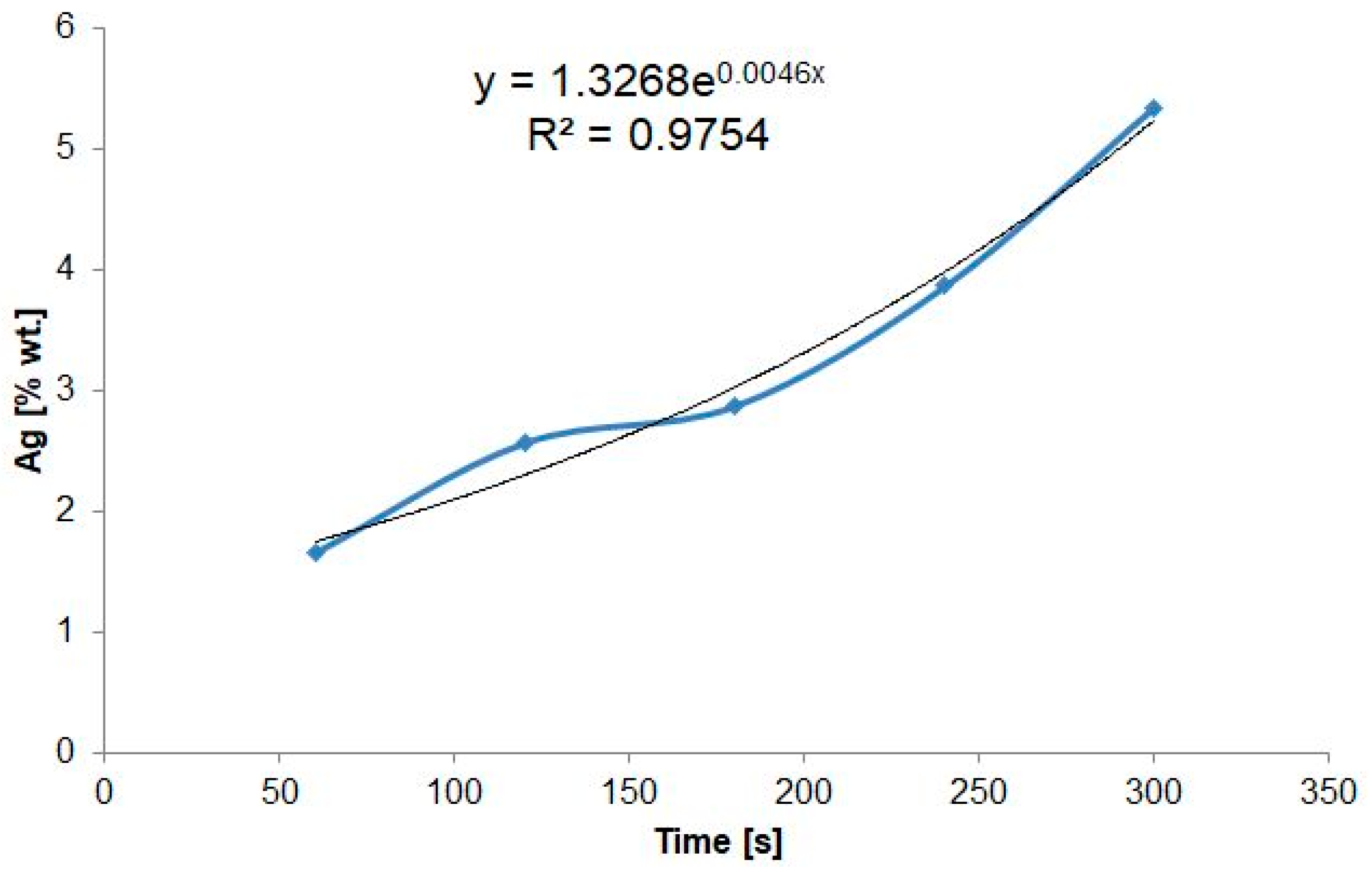
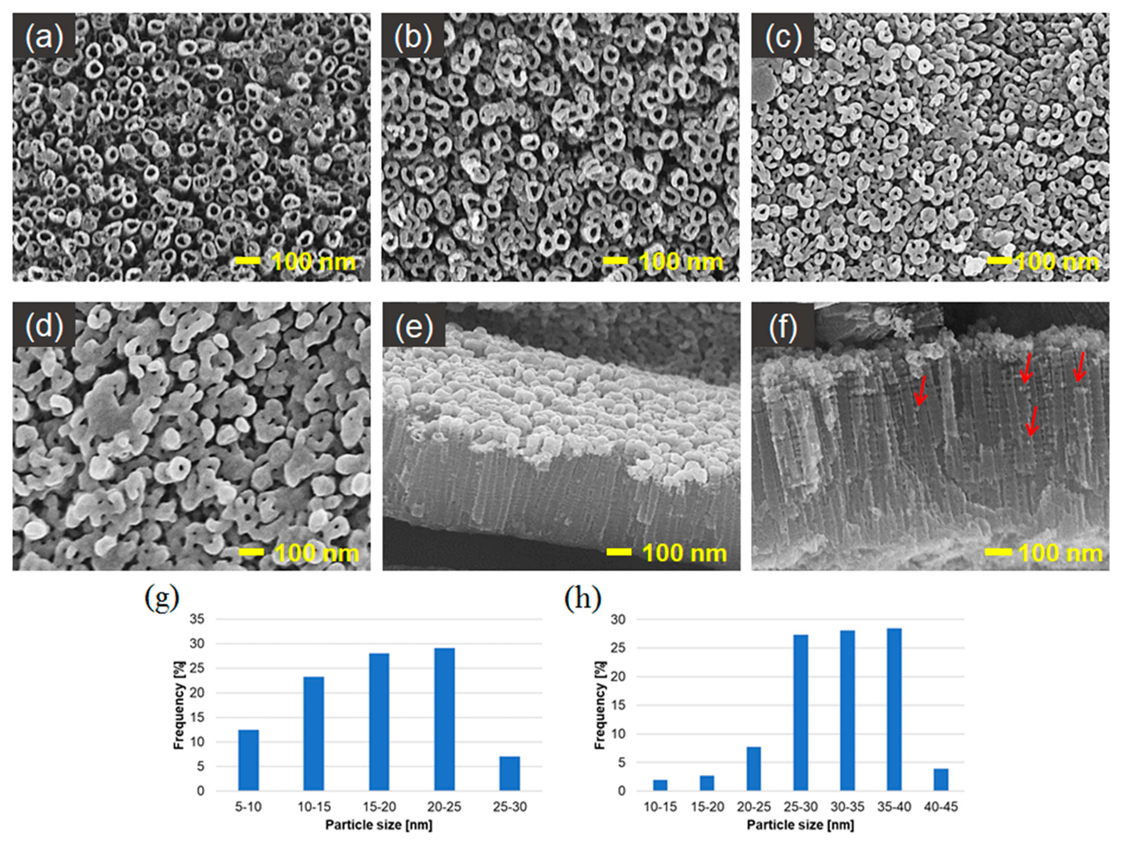
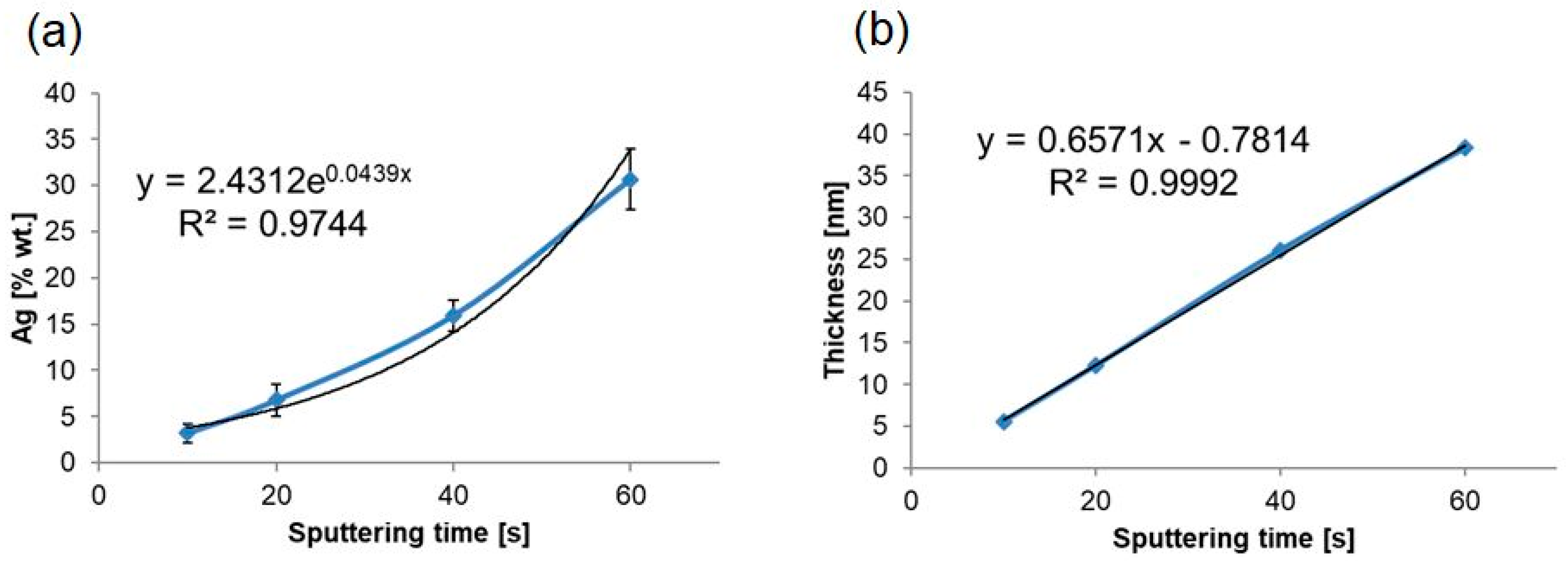
  • Produced silver spherical and near-spherical nanoparticles were concentrated mostly in the upper part of nanotubes around their rings and, to a lesser extent, also filled the space between the nanotubes and permeated into them. With the increase in duration of deposition, an increase in the spread of the size of nanoparticles, and an increase in the most frequent value of these sizes was observed. In the case of cyclic voltammetry, there occurred a linear growth of % silver weight content in the structure along with the increased number of cycles to 25, after which the layer became saturated. In the case of chronoamperometry and sputter deposition exponential growth of % wt. of Ag in time was noted.
  • Generally, the addition of silver to the structure increased the OCP value, which in turn increased the corrosion resistance of these structures. In the case of electrodeposition it can be noticed that a shorter duration of nanoparticles deposition/lower number of cycles results in creating platforms whose OCP has positive values. This probably occurs because of a greater number of unreduced silver ions in non-stabilized structures rich in agglomerates.
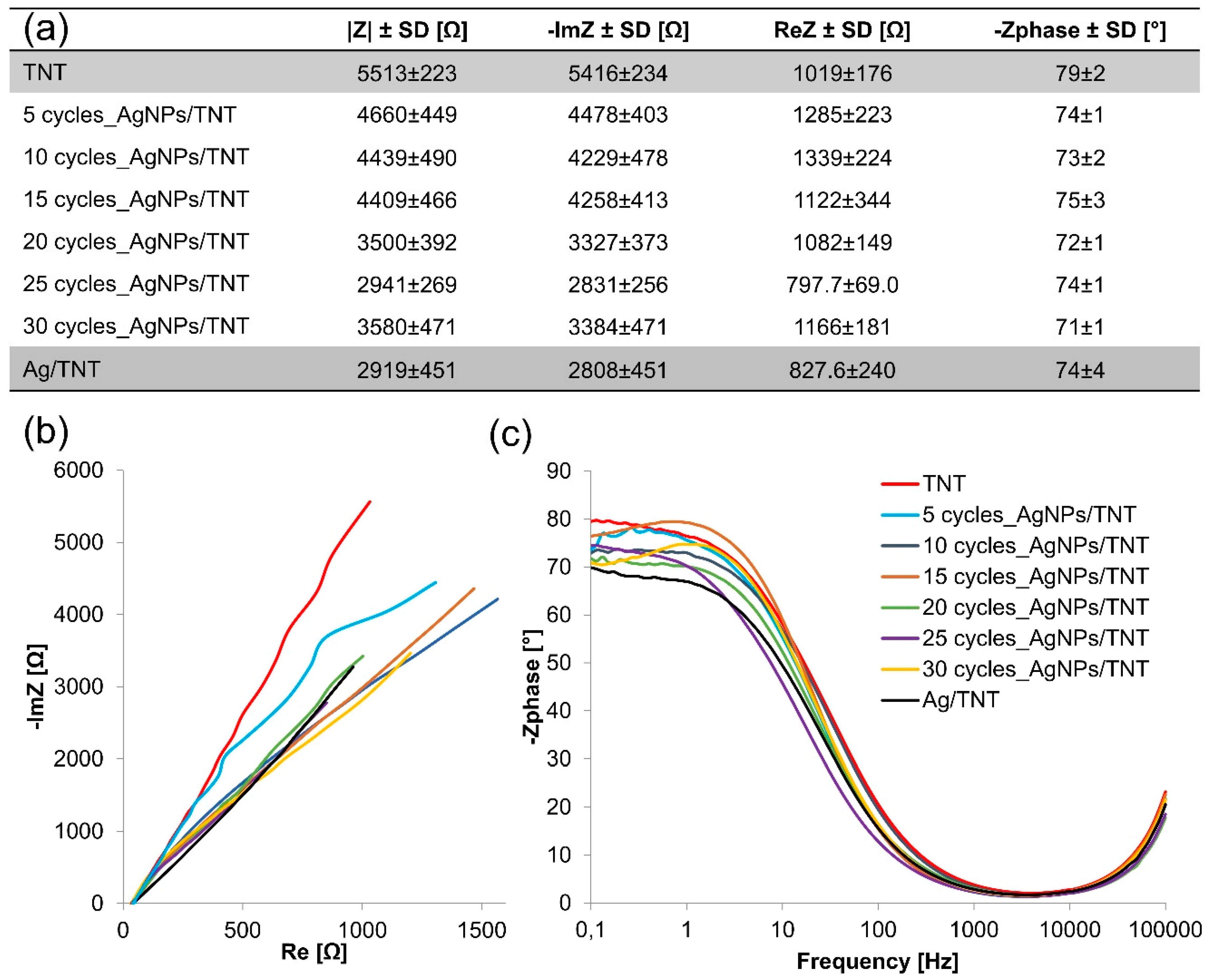
  • Nanoparticles caused a decrease in the impedance module (up to 50% lower when compared to TNT) and hence increased conductivity of the created electrodes. The highest conductivity among all samples without agglomerates was noted for the electrode after 25 cycles of AgNPs deposition by cyclic voltammetry (25 cycles_AgNPs/TNT).

Author Contributions

Data curation, M.N.; Formal analysis, M.N.; Funding acquisition, M.N.; Investigation, M.N.; Methodology, K.A.; Supervision, D.G.P.; Writing—original draft, M.N.; Writing—review & editing, K.A. and D.G.P.

Funding

M.N., K.A., D.G.P. acknowledge the financial support from the program of the Polish Minister of Science and Higher Education under the name “Regional Initiative of Excellence” in 2019–2022, project No. 003/RID/2018/19, funding amount 11 936 596.10 PLN, and from the National Science Center (Poland) - grant number 2017/27/N/ST7/01702.

Conflicts of Interest

The authors declare no conflict of interest.

References

  1. Dervisevic, M.; Cevik, E.; Durmus, Z.; Senel, M. Electrochemical sensing platforms based on the different carbon derivative incorporated interface. Mater. Sci. Eng. C 2016, 58, 790–798. [Google Scholar] [CrossRef] [PubMed]
  2. Shoja, Y.; Rafati, A.A.; Ghodsi, J. Glassy carbon electrode modified with horse radish peroxidase/organic nucleophilic-functionalized carbon nanotube composite for enhanced electrocatalytic oxidation and efficient voltammetric sensing of levodopa. Mater. Sci. Eng. C 2016, 58, 835–845. [Google Scholar] [CrossRef] [PubMed]
  3. Wang, L.; Zhang, Q.; Chen, S.; Xu, F.; Chen, S.; Jia, J.; Tan, H.; Hou, H.; Song, Y. Electrochemical sensing and biosensing platform based on biomass-derived macroporous carbon materials. Anal. Chem. 2014, 86, 1414–1421. [Google Scholar] [CrossRef] [PubMed]
  4. Hasanzadeh, M.; Shadjou, N.; de la Guardia, M.; Eskandani, M.; Sheikhzadeh, P. Mesoporous silica-based materials for use in biosensors. Trends Anal. Chem. 2012, 33, 117–129. [Google Scholar] [CrossRef]
  5. Gerard, M.; Chaubey, A.; Malhotra, B.D. Application of conducting polymers to biosensors. Biosens. Bioelectron. 2002, 17, 345–359. [Google Scholar] [CrossRef]
  6. Wang, X.; Uchiyama, S. Polymers for biosensors construction. In State of the Art in Biosensors – General Aspects; Rinken, T., Ed.; InTech: London, UK, 2013; pp. 67–86. [Google Scholar]
  7. Bianchi, R.C.; da Silva, E.R.; Dall‘Antonia, L.H.; Ferreira, F.F.; Alves, W.A. A nonenzymatic biosensor based on gold electrodes modified with peptide self-assemblies for detecting ammonia and urea oxidation. Langmuir 2014, 30, 11464–11473. [Google Scholar] [CrossRef] [PubMed]
  8. Bai, Z.; Li, G.; Liang, J.; Su, J.; Zhang, Y.; Chen, H.; Huang, Y.; Sui, W.; Zhao, Y. Non-enzymatic electrochemical biosensor based on Pt NPs/RGO-CS-Fc nano-hybrids for the detection of hydrogen peroxide in living cells. Biosens. Bioelectron. 2016, 82, 185–194. [Google Scholar] [CrossRef] [PubMed]
  9. Sandulescu, R.; Tertis, M.; Cristea, C.; Bodoki, E. New materials for the construction of electrochemical biosensors. In Biosensors - Micro and Nanoscale Applications; Rinken, T., Ed.; InTech: London, UK, 2015; pp. 1–36. [Google Scholar]
  10. Holzinger, M.; Le Goff, A.; Cosnier, S. Nanomaterials for biosensing applications: a review. Front. Chem. 2014, 2, 1–10. [Google Scholar] [CrossRef]
  11. Bai, J.; Zhou, B. Titanium dioxide nanomaterials for sensor applications. Chem. Rev. 2014, 114, 10131–10176. [Google Scholar] [CrossRef]
  12. Lee, K.; Mazare, A.; Schmuki, P. One-dimensional titanium dioxide nanomaterials: nanotubes. Chem. Rev. 2014, 114, 9385–9454. [Google Scholar] [CrossRef]
  13. Zeng, S.; Yong, K.T.; Roy, I.; Dinh, X.Q.; Yu, X.; Luan, F. A review on functionalized gold nanoparticles for biosensing applications. Plasmonics 2011, 6, 491–506. [Google Scholar] [CrossRef]
  14. Ngece, R.F.; West, N.; Ndangili, P.M.; Olowu, R.A. A silver Nanoparticle/Poly (8-Anilino-1-Naphthalene Sulphonic Acid) bioelectrochemical biosensor system for the analytical determination of ethambutol. Int. J. Electrochem. Sci. 2011, 6, 1820–1834. [Google Scholar]
  15. Chang, G.H.; Luo, Y.L.; Lu, W.B.; Liao, F.; Sun, X. Hydrothermal synthesis of ultra-highly concentrated; well-stable Ag nanoparticles and their application for enzymeless hydrogen peroxide detection. J. Nanoparticle. Res. 2011, 13, 2689–2695. [Google Scholar] [CrossRef]
  16. Khan, M.J.; Husain, Q.; Ansari, S.A. Polyaniline-assisted silver nanoparticles: a novel support for the immobilization of α-amylase. Appl. Microbiol. Biotechnol. 2013, 97, 1513–1522. [Google Scholar] [CrossRef] [PubMed]
  17. Narang, J.; Chauhan, N.; Jain, P.; Pundir, C.S. Silver nanoparticles/multiwalled carbon nanotube/polyaniline film for amperometric glutathione biosensor. Int. J. Biol. Macromol. 2012, 50, 672–678. [Google Scholar] [CrossRef] [PubMed]
  18. Feng, C.; Xu, G.; Liu, H.; Lv, J.; Zheng, Z.; Wu, Y. Glucose biosensors based on Ag nanoparticles modified TiO2 nanotube arrays. J. Solid State Electrochem. 2014, 18, 163–171. [Google Scholar] [CrossRef]
  19. Jiang, Y.; Zheng, B.; Du, J.; Liu, G.; Guo, Y.; Xiao, D. Electrophoresis deposition of Ag nanoparticles on TiO2 nanotube arrays electrode for hydrogen peroxide sensing. Talanta 2013, 112, 129–135. [Google Scholar] [CrossRef]
  20. Zhao, L.; Wang, H.; Huo, K.; Cui, L.; Zhang, W.; Ni, H.; Zhang, Y.; Wu, Z.; Chu, P.K. Antibacterial nanostructured titania coating incorporated with silver nanoparticles. Biomaterials 2011, 32, 5706–5716. [Google Scholar] [CrossRef]
  21. Roguska, A.; Belcarz, A.; Piersiak, T.; Pisarek, M. Evaluation of the antibacterial activity of Ag-loaded TiO2 nanotubes. Eur. J. Inorg. Chem. 2012, 5199–5206. [Google Scholar] [CrossRef]
  22. Paramasivam, I.; Macak, J.M.; Schmuki, P. Photocatalytic activity of TiO2 nanotube layers loaded with Ag and Au nanoparticles. Electrochem. Commun. 2008, 10, 71–75. [Google Scholar] [CrossRef]
  23. Syrek, K.; Grudzień, J.; Sennik-Kubiec, A.; Brudzisz, A.; Sulka, G.D. Anodic titanium oxide layers modified with gold, silver, and copper nanoparticles. J. Nano 2019, 1–10. [Google Scholar] [CrossRef]
  24. Wang, Q.; Yang, X.; Liu, D.; Chi, L. Ag and CdS nanoparticles co-sensitized TiO2 nanotubes for enhancing visible photoelectrochemical performance. Electrochim. Acta 2012, 83, 140–145. [Google Scholar] [CrossRef]
  25. Gudikandula, K.; Maringanti, S.C. Synthesis of silver nanoparticles by chemical and biological methods and their antimicrobial properties. J. Exp. Nanosci. 2016, 11, 714–721. [Google Scholar] [CrossRef]
  26. Starowicz, M.; Stypuła, B.; Banaś, J.; Kasprzyk, D. Electrochemical synthesis of silver nanoparticles. Electrochem. Commun. 2006, 8, 227–230. [Google Scholar] [CrossRef]
  27. Mafuné, F.; Kohno, J.Y.; Takeda, Y.; Kondow, T.; Sawabe, H. Formation and size control of silver nanoparticles by laser ablation in aqueous solution. J. Phys. Chem. B 2000, 104, 9111–9117. [Google Scholar] [CrossRef]
  28. Surmeneva, M.A.; Sharonova, A.A.; Chernousova, S.; Prymak, O.; Loza, K.; Tkachev, M.S.; Shulepov, I.A.; Epple, M.; Surmenev, R.A. Incorporation of silver nanoparticles into magnetron-sputtered calcium phosphate layers on titanium as anantibacterial coating. Colloids Surf. B 2017, 156, 104–113. [Google Scholar] [CrossRef] [PubMed]
  29. Oluwafemi, O.S.; Mochochoko, T.; Leo, A.J.; Mohan, S.; Jumbam, D.N.; Songca, S.P. Microwave irradiation synthesis of silver nanoparticles using cellulose from Eichhornia crassipes plant shoot. Mater. Lett. 2016, 185, 576–579. [Google Scholar] [CrossRef]
  30. Vinoth, V.; Wu, J.J.; Asiri, A.M.; Anandan, S. Sonochemical synthesis of silver nanoparticles anchored reduced graphene oxide nanosheets for selective and sensitive detection of glutathione. Ultrason. Sonochem. 2017, 39, 363–373. [Google Scholar] [CrossRef]
  31. Paramasivam, I.; Macak, J.M.; Ghicov, A.; Schmuki, P. Enhanced photochromism of Ag loaded selforganized TiO2 nanotube layers. Chem. Phys. Lett. 2007, 445, 233–237. [Google Scholar] [CrossRef]
  32. Baran, E.; Yazici, B. Effect of different nano-structured Ag doped TiO2-NTs fabricated by electrodeposition on the electrocatalytic hydrogen production. Int. J. Hydrogen Energy 2016, 41, 2498–2511. [Google Scholar] [CrossRef]
  33. Brugnera, M.F.; Miyata, M.; Leite, C.Q.F.; Zanoni, M.V.B. Silver ion release from electrodes of nanotubes of TiO2 impregnated with Ag nanoparticles applied in photoelectrocatalytic disinfection. J. Photochem. Photobiol. A Chem. 2014, 278, 1–8. [Google Scholar] [CrossRef]
  34. Liu, X.; Liu, Z.; Hao, S.; Chu, W. Facile fabrication of well-dispersed silver nanoparticles loading on TiO2 nanotubearrays by electrodeposition. Mater. Lett. 2012, 80, 66–68. [Google Scholar] [CrossRef]
  35. Li, J.; Yang, L.; Luo, S.; Chen, B.; Li, J.; Lin, H.; Cai, Q.; Yao, S. Polycyclic Aromatic Hydrocarbon Detection by Electrochemiluminescence Generating Ag/TiO2. Anal. Chem. 2010, 82, 7357–7361. [Google Scholar] [CrossRef]
  36. Roguska, A.; Kudelski, A.; Pisarek, M.; Opara, M.; Janik-Czachor, M. Raman investigations of SERS activity of Ag nanoclusters on a TiO2-nanotubes/Ti substrate. Vibrat. Spectr. 2011, 55, 38–43. [Google Scholar] [CrossRef]
  37. Salari, M.; Aboutalebi, S.H.; Chidembo, A.T.; Nevirkovets, I.P.; Konstantinov, K.; Liu, H.K. Enhancement of the electrochemical capacitance of TiO2 nanotube arrays through controlled phase transformation of anatase to rutile. Phys. Chem. Chem. Phys. 2012, 14, 4770–4779. [Google Scholar] [CrossRef]
  38. Arkusz, K.; Paradowska, E.; Nycz, M.; Krasicka-Cydzik, E. Influence of Thermal Modification and Morphology of TiO2 nanotubes on their electrochemical properties for biosensors applications. J. Nanosci. Nanotechnol. 2018, 18, 3713–3721. [Google Scholar] [CrossRef]
  39. Arkusz, K.; Nycz, M.; Paradowska, E.; Krasicka-Cydzik, E. Electrochemical detection method for interleukin-6 on titania nanotube platforms. Eng. Biomater. 2014, 17, 21–29. [Google Scholar]
  40. Leu, W.L.; Wang, N.; Gao, P.; Li, C.Y.; Zhao, H.S.; Zhang, Z.T. Effects of anodic titanium dioxide nanotubes of different diameters on macrophage secretion and expression of cytokines and chemokines. Cell Proliferat. 2015, 48, 95–104. [Google Scholar] [CrossRef]
  41. Liu, D.; Xiao, P.; Zhang, Y.; Garcia, B.B. TiO2 nanotube arrays annealed in N2 for efficient lithium-ion intercalation. J. Phys. Chem. C 2018, 112, 11175–11180. [Google Scholar] [CrossRef]
  42. Salari, M.; Konstantinov, K.; Liu, H.K. Enhancement of the capacitance in TiO2 nanotubes through controlled introduction of oxygen vacancies. J. Mater. Chem. 2011, 21, 5128–5133. [Google Scholar] [CrossRef]
  43. Ghicov, A.; Tsuchiya, H.; Macak, J.M.; Schmuki, P. Annealing effects on the photoresponse of TiO2 nanotubes. Phys. Stat. Sol. A 2006, 203, 28–30. [Google Scholar] [CrossRef]
  44. Wang, Y.; Liu, S.; Huang, K.; Dong, F.; Zhuang, S. Electrochemical properties of freestanding TiO2 nanotube membranes annealed in Ar for lithium anode material. J. Solid. State Electr. 2012, 16, 723–729. [Google Scholar] [CrossRef]
  45. Huang, Q.; Yang, Y.; Zheng, D.; Song, R.; Zhang, Y.; Jiang, P.; Vogler, E.A.; Lin, C. Effect of construction of TiO2 nanotubes on platelet behaviors: Structure-property relationships. Acta Biomater. 2017, 51, 505–512. [Google Scholar] [CrossRef]
  46. Liang, Y.Q.; Cui, Z.D.; Zhu, S.L.; Liu, Y.; Yang, X.Y. Silver nanoparticles supported on TiO2 nanotubes as active catalysts for ethanol oxidation. J. Catal. 2011, 278, 276–287. [Google Scholar] [CrossRef]
  47. Bai, Y.; Bai, Y.; Wang, C.; Gao, J.; Ma, W. Fabrication and characterization of gold nanoparticle-loaded TiO2 nanotube arrays for medical implants. J. Mater. Sci. Mater. Med. 2016, 27, 31. [Google Scholar] [CrossRef]
  48. Kim, H.S.; Chun, M.H.; Suh, J.S.; Jun, B.-H.; Rho, W.-Y. Dual functionalized freestanding TiO2 nanotube arrays coated with Ag nanoparticles and carbon materials for dye-sensitized solar cells. App. Sci. 2017, 7, 576. [Google Scholar] [CrossRef]
  49. Azadbakht, A.; Abbasi, A.R.; Derikvand, Z.; Karimi, Z.; Roushani, M. Surface-renewable AgNPs/CNT/rGO nanocomposites as bifunctional impedimetric sensors. Nano-Micro Lett. 2017, 9, 1–11. [Google Scholar] [CrossRef]
  50. Raghav, R.; Srivastava, S. Core–shell gold–silver nanoparticles based impedimetric immunosensor for cancer antigen CA125. Sens. Actuators B 2015, 220, 557–564. [Google Scholar] [CrossRef]
  51. Huang, K.J.; Liu, Y.J.; Wang, H.B.; Wang, Y.Y. A sensitive electrochemical DNA biosensor based on silver nanoparticles - polydopamine@graphene composite. Electrochim. Acta 2014, 118, 130–137. [Google Scholar] [CrossRef]
  52. Gonzalez-Campos, J.B.; Prokhorov, E.; Luna-Barcenas, G.; Sanchez, I.C.; Lara-Romero, J.; Mendoza-Duarte, M.E.; Villasenor, F.; Guevara-Olvera, L. Chitosan/silver nanoparticles composite: molecular relaxations investigation by dynamic mechanical analysis and impedance spectroscopy. J. Polym. Sci. B Polym. Phys. 2010, 48, 739–748. [Google Scholar] [CrossRef]
  53. Khalilzadeh, M.A.; Borzoo, M. Green synthesis of silver nanoparticles using onion extract and their application for the preparation of a modified electrode for determination of ascorbic acid. J. Food Drug Anal. 2016, 24, 796–803. [Google Scholar] [CrossRef]
  54. Chawla, S.; Rawal, R.; Kumar, D.; Pundir, C.S. Amperometric determination of total phenolic content in wine by laccase immobilized onto silver nanoparticles/zinc oxide nanoparticles modified gold electrode. Analyt. Biochem. 2012, 430, 16–23. [Google Scholar] [CrossRef]
  55. Xu, Q.; Wang, G.; Zhang, M.; Xu, G.; Lin, J.; Luo, X. Aptamer based label free thrombin assay based on the use of silver nanoparticles incorporated into self-polymerized dopamine. Microchim. Acta 2018, 185, 1–7. [Google Scholar] [CrossRef]
  56. Sha, H.; Zheng, W.; Shi, F.; Wang, X.; Sun, W. Direct electrochemistry of hemoglobin on electrodeposited three-dimensional interconnected graphene-silver nanocomposite modified electrode. Int. J. Electrochem. Sci. 2016, 11, 9656–9665. [Google Scholar] [CrossRef]
  57. Chen, K.; Feng, X.; Hu, R.; Li, Y. Effect of Ag nanoparticle size on the photoelectrochemical properties of Ag decorated TiO2 nanotube arrays. J. Alloys Compd. 2013, 554, 72–79. [Google Scholar] [CrossRef]
Figure 1. SEM top-view and cross-sectional (on insets) images of: (a) TNT and (b) Ag/TNT reference electrodes.
Nanomaterials 09 01072 g001
Figure 2. SEM top-view images of AgNPs/TNT platforms prepared by voltammetric method by: (a) 5, (b) 10, (c) 15, (d) 20, (e) 25, (f) 30 cycles, (g), (h) crss-sectional images of 25 cycles_AgNPs/TNT and histograms of particle-size distribution for: (i) 20 cycles_AgNPs/TNT, (j) 25 cycles_AgNPs/TNT.
Nanomaterials 09 01072 g002
Figure 3. Chart presenting a number of deposition cycles dependence on silver weight content in produced AgNPs/TNT platforms.
Nanomaterials 09 01072 g003
Figure 4. Summary of impedance parameters (a), Nyquist (b) and Bode (c) plots of AgNPs/TNT platforms differing in the number of cycles of silver nanoparticles deposition and reference layers: TNT and Ag/TNT. Spectra were recorded in the PBS solution (0.01 M, 10 ml, pH 7.4) over the frequency range 0.1–105 Hz with amplitude 10 mV.
Nanomaterials 09 01072 g004
Figure 5. SEM top-view images of AgNPs/TNT platforms prepared by chronoamperometry for: (a) 30 s, (b) 60 s, (c) 120 s, (d) 180 s, (e) 240 s, (f) 300 s and histograms of particle-size distribution for: (g) 60 chrono_ AgNPs/TNT, (h) 120 chrono_ AgNPs/TNT, (i) 180 chrono_ AgNPs/TNT.
Nanomaterials 09 01072 g005
Figure 6. Chart of deposition duration dependency on the silver weight content in produced AgNPs/TNT platforms.
Nanomaterials 09 01072 g006
Figure 7. Summary of impedance parameters (a), Nyquist (b) and Bode (c) plots of AgNPs/TNT platforms differing in time of silver nanoparticles deposition and reference layers: TNT and Ag/TNT. Spectra were recorded in the PBS solution (0.01 M, 10 ml, pH 7.4) over the frequency range 0.1–105 Hz with amplitude 10 mV.
Nanomaterials 09 01072 g007
Figure 8. SEM top-view images of AgNPs/TNT platforms prepared by sputter deposition after: (a) 10 s, (b) 20 s, (c) 40 s, (d) 60 s, (e), (f) cross-sectional images of 20 target_AgNPs/TNT and histograms of particle-size distribution for: (g) 10 target__AgNPs/TNT, (h) 20 target_ AgNPs/TNT.
Nanomaterials 09 01072 g008
Figure 9. Chart presenting deposition duration dependency on the: (a) silver weight content and (b) thickness of silver layer in produced AgNPs/TNT platforms.
Nanomaterials 09 01072 g009
Figure 10. Summary of impedance parameters (a), Nyquist (b) and Bode (c) plots of AgNPs/TNT platforms differing in time of sputter deposition of silver and reference layers: TNT and Ag/TNT. Spectra were recorded in the PBS solution (0.01 M, 10 ml, pH 7.4) over the frequency range 0.1–105 Hz with amplitude 10 mV.
Nanomaterials 09 01072 g010
Table 1. Summary of the naming of the performed electrodes.
SampleDescription
x cycles_AgNPs/TNTTNT with AgNPs deposited using CV in 1 mM AgNO3; where x – number of cycles: x = 5, 10, 15, 20, 25, 30.
x chrono_AgNPs/TNTTNT with AgNPs deposited using CA in 1 mM AgNO3; where x – time of deposition: x = 30, 60, 120, 180, 240, 300.
x target_AgNPs/TNTTNT with AgNPs deposited using SD; where x – time of deposition: x = 10, 20, 40, 60.
Ag/TNTTNT with silver micro layer deposited using CV in 50 mM AgNO3 for 25 cycles.
Table 2. The values of OCP and size of AgNPs deposited on TNT platforms prepared by voltammetric method.
AgNPs/TNTAg/TNT
Number of cycles5101520253025
Size of AgNPs5–80 a nm5–50 a nm5–40 a nm5–40 nm5–40 nm5–70 a nmlayer a
OCP [mV] versus Ag/AgCl−18.0 ± 248.11 ± 1527.0 ± 23−18.9 ± 9−2.6 ± 2−16.7 ± 1326.9 ± 18
a – platform with agglomerates.
Table 3. The values of OCP and size of AgNPs deposited on TNT platforms prepared by chronoamperometry method.
AgNPs/TNT
Time [s]3060120180240300
Size of AgNPs5–30a nm5–25 nm5–35 nm5–45 nm10–50 nm10–70 a nm
OCP [mV] versus Ag/AgCl4.00 ± 1921.6 ± 2317.2 ± 13−18.9 ± 20−13.6 ± 12−26 ± 1
a – platform with agglomerates.

