Multifunctional Superparamagnetic Stiff Nanoreservoirs for Blood Brain Barrier Applications

 ,
,  ,
,  ,
,
Abstract
:
1. Introduction
2. Materials and Methods
2.1. Chemicals and Synthesis Chemicals
2.2. Synthesis of Fluorescent Magnetic Mesoporous Nanorods
2.3. Physicochemical Characterization
2.3.1. XRD-Structural Characterization
2.3.2. Microscopy Morphological Characterization
2.3.3. Surface Chemistry Characterization
2.3.4. Compositional Characterization
2.3.5. Textural Characterization
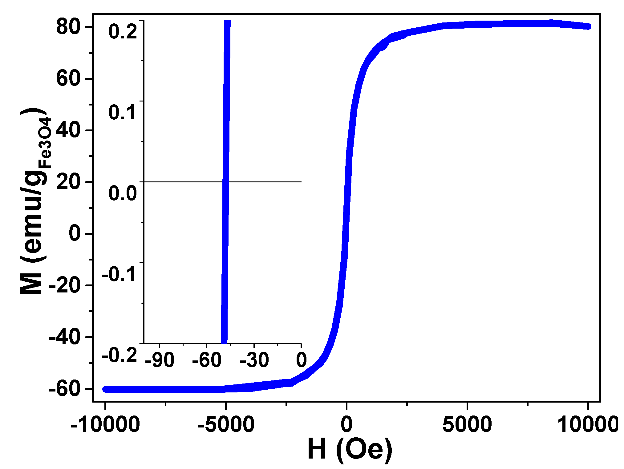
2.3.6. Magnetic Characterization
2.4. Biological Characterization
2.4.1. In Vivo Magnetic Resonance Imaging
2.4.2. In Vitro Cell Mortality
2.4.3. Prussian Blue Stain and Imaging
2.4.4. In Vivo Experimental Groups
3. Results and Discussion
3.1. Physicochemical Properties
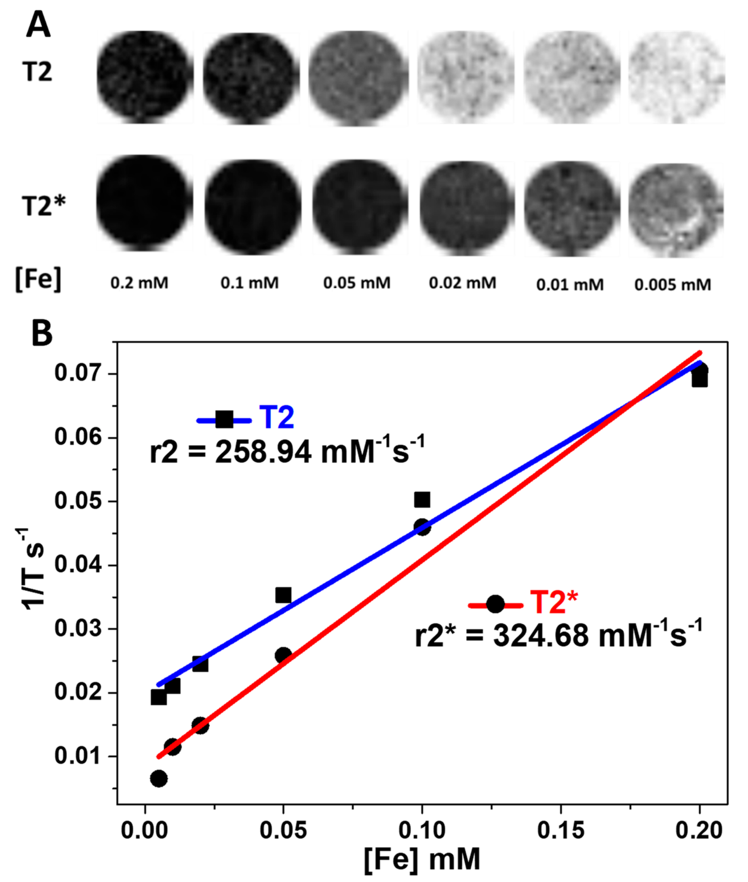
3.2. Relaxivity and Brain MRI Contrast of the HMMSN Nanorods
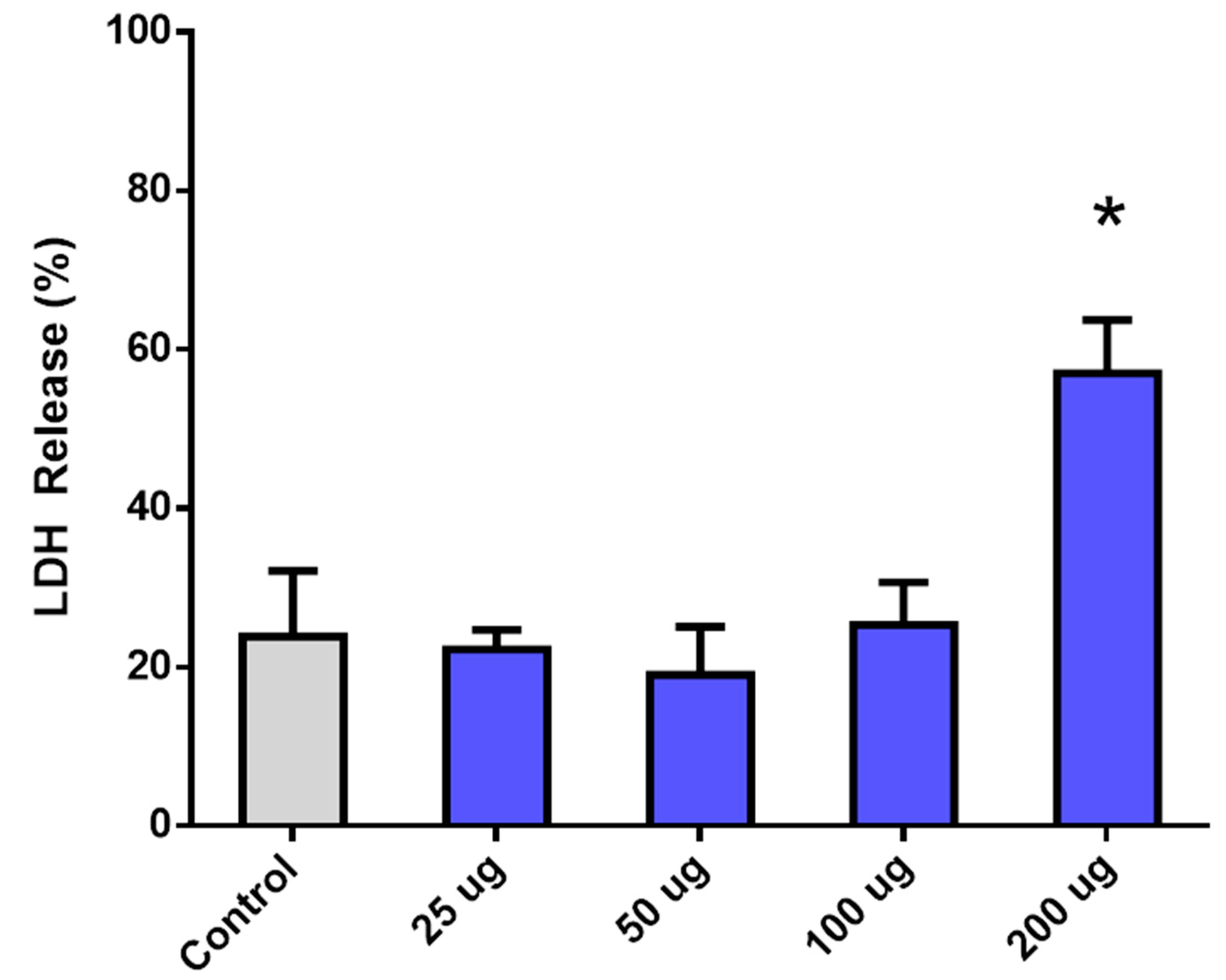
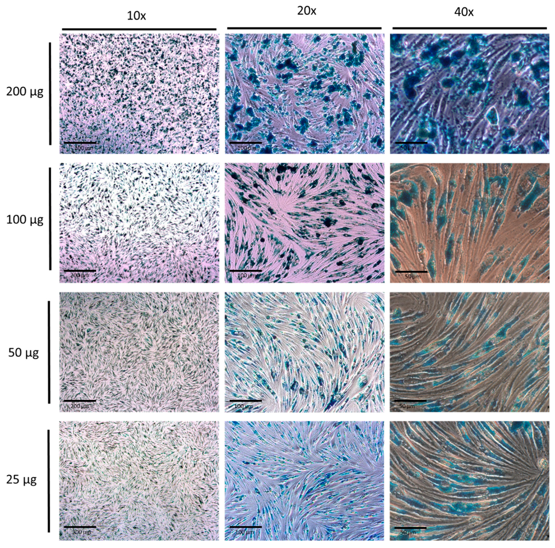
3.3. In Vitro Cell Mortality by LDH Toxicity Assay and Prussian Blue Stain of the HMMSN Nanorods
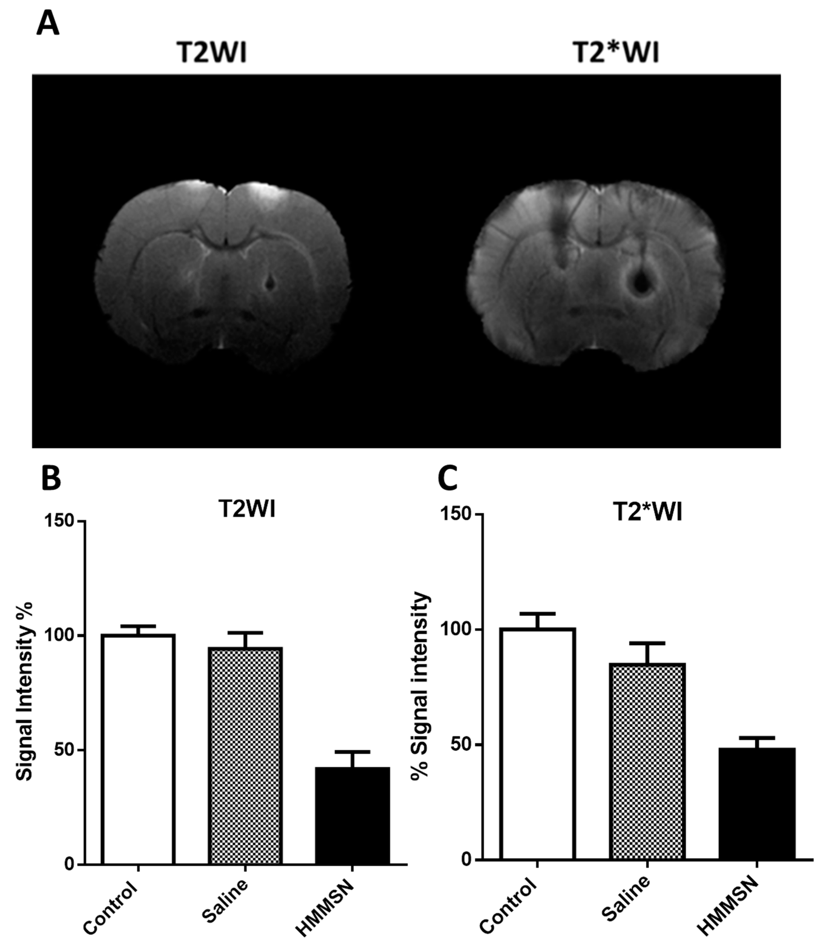
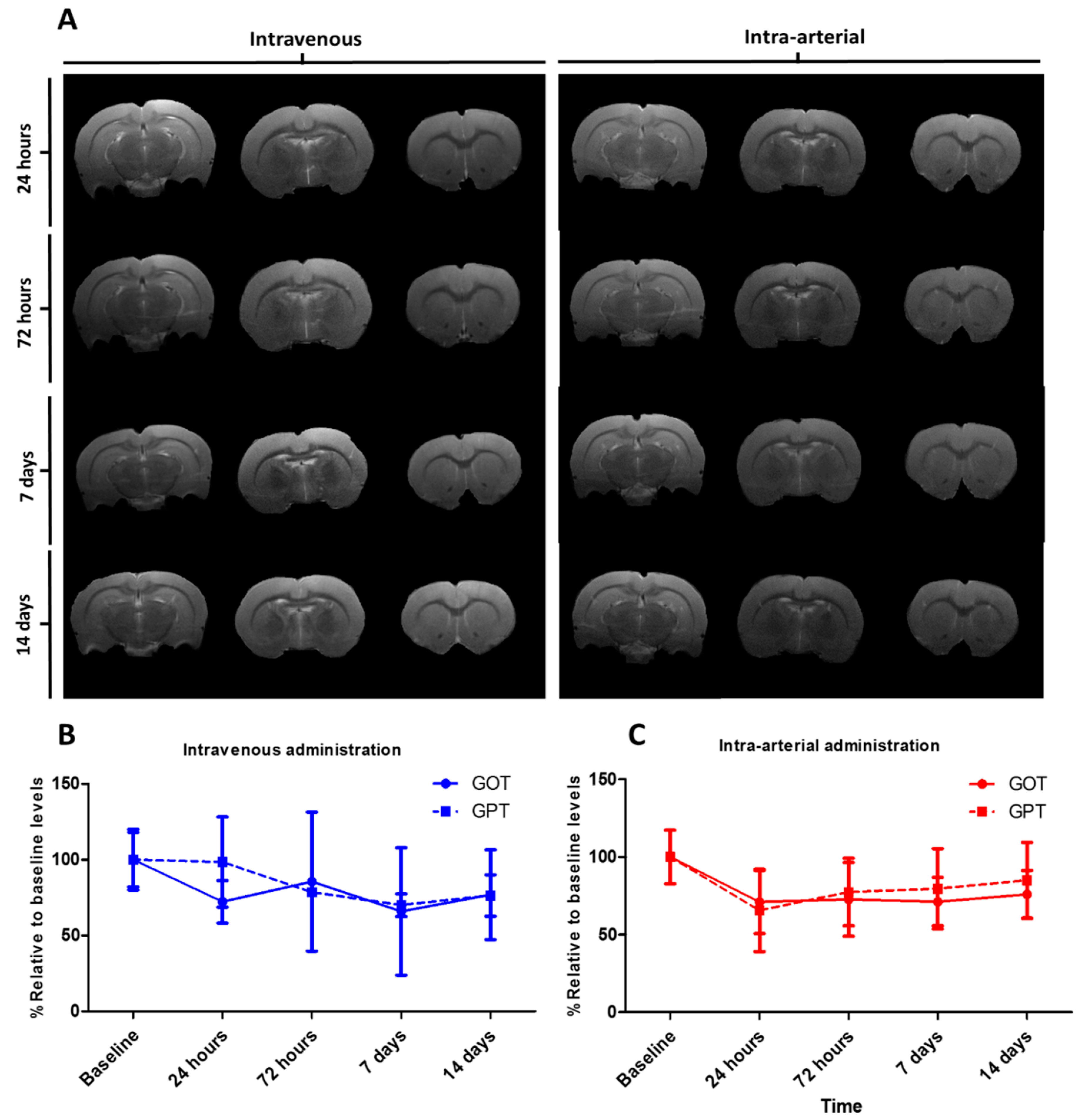
3.4. Brain MRI Evaluation after Intravenous and Intra-Arterial Injections and In Vivo Toxicity of the HMMSN Nanorods
4. Conclusions
Author Contributions
Funding
Conflicts of Interest
Abbreviations
References
- Meyers, J.D.; Doane, T.; Burda, C.; Basilion, J.P. Nanoparticles for Imaging and Treating Brain Cancer. Nanomedicine 2013, 8, 123–143. [Google Scholar] [CrossRef]
- Bhojani, M.S.; Van Dort, M.; Rehemtulla, A.; Ross, B.D. Targeted Imaging and Therapy of Brain Cancer Using Theranostic Nanoparticles. Mol. Pharm. 2010, 7, 1921–1929. [Google Scholar] [CrossRef] [PubMed]
- Lv, G.; Guo, W.; Zhang, W.; Zhang, T.; Li, S.; Chen, S.; Eltahan, A.S.; Wang, D.; Wang, Y.; Zhang, J.; et al. Near-Infrared Emission CuInS/ZnS Quantum Dots: All-in-One Theranostic Nanomedicines with Intrinsic Fluorescence/Photoacoustic Imaging for Tumor Phototherapy. ACS Nano 2016, 10, 9637–9645. [Google Scholar] [CrossRef] [PubMed]
- Silva-Candal, A.; Argibay, B.; Iglesias-Rey, R.; Vargas, Z.; Vieites-Prado, A.; López-Arias, E.; Rodríguez-Castro, E.; López-Dequidt, I.; Rodríguez-Yáñez, M.; Piñeiro, Y.; et al. Vectorized Nanodelivery Systems for Ischemic Stroke: A Concept and a Need. J. Nanobiotechnol. 2017, 15, 30. [Google Scholar] [CrossRef] [PubMed]
- Masserini, M. Nanoparticles for Brain Drug Delivery. ISRN Biochem. 2013, 2013, 238428. [Google Scholar] [CrossRef] [PubMed]
- Baghirov, H.; Karaman, D.; Viitala, T.; Duchanoy, A.; Lou, Y.R.; Mamaeva, V.; Pryazhnikov, E.; Khiroug, L.; De Lange Davies, C.; Sahlgren, C.; et al. Feasibility Study of the Permeability and Uptake of Mesoporous Silica Nanoparticles across the Blood-Brain Barrier. PLoS ONE 2016, 11, e0160705. [Google Scholar] [CrossRef]
- Posadas, I.; Monteagudo, S.; Ceña, V. Nanoparticles for Brain-Specific Drug and Genetic Material Delivery, Imaging and Diagnosis. Nanomedicine 2016, 11, 833–849. [Google Scholar] [CrossRef]
- Saraiva, C.; Praça, C.; Ferreira, R.; Santos, T.; Ferreira, L.; Bernardino, L. Nanoparticle-mediated brain drug delivery: Overcoming blood-brain barrier to treat neurodegenerative diseases. Control. Release 2016, 235, 34–47. [Google Scholar] [CrossRef]
- Ceña, V.; Játiva, P. Nanoparticle crossing of blood-brain barrier: A road to new therapeutic approaches to central nervous system diseases. Nanomedicine 2018, 13, 1513–1516. [Google Scholar] [CrossRef]
- Vargas-Osorio, Z.; Argibay, B.; Piñeiro, Y.; Vázquez-Vázquez, C.; López-Quintela, M.A.; Álvarez-Perez, M.A.; Sobrino, T.; Campos, F.; Castillo, J.; Rivas, J. Multicore Magnetic Fe3O4@C Beads with Enhanced Magnetic Response for MRI in Brain Biomedical Applications. IEEE Trans. Magn. 2016, 52, 2300604. [Google Scholar] [CrossRef]
- Hao, X.; Hu, X.; Zhang, C.; Chen, S.; Li, Z.; Yang, X.; Liu, H.; Jia, G.; Liu, D.; Ge, K.; et al. Hybrid Mesoporous Silica-Based Drug Carrier Nanostructures with Improved Degradability by Hydroxyapatite. ACS Nano 2015, 9, 9614–9625. [Google Scholar] [CrossRef] [PubMed]
- Peng, J.R.; Qi, T.T.; Liao, J.F.; Chu, B.Y.; Yang, Q.; Qu, Y.; Li, W.T.; Li, H.; Luo, F.; Qian, Z.Y. Mesoporous Magnetic Gold “nanoclusters” as Theranostic Carrier for Chemo-Photothermal Co-Therapy of Breast Cancer. Theranostics 2014, 4, 678–692. [Google Scholar] [CrossRef] [PubMed]
- Sahoo, B.; Devi, K.S.P.; Dutta, S.; Maiti, T.K.; Pramanik, P.; Dhara, D. Biocompatible Mesoporous Silica-Coated Superparamagnetic Manganese Ferrite Nanoparticles for Targeted Drug Delivery and MR Imaging Applications. J. Colloid Interface Sci. 2014, 431, 31–41. [Google Scholar] [CrossRef]
- Vargas-Osorio, Z.; Luzardo-Álvarez, A.; Piñeiro, Y.; Vázquez-Vázquez, C.; Gómez-Amoza, J.L.; Blanco-Méndez, J.; Otero Espinar, F.J.; Rivas, J. 3D Hybrid Mesoporous Scaffolds for Simvastatin Sustained Delivery With in Vitro Cell Compatibility. ACS Omega 2019. [Google Scholar] [CrossRef]
- Giri, S.; Trewyn, B.G.; Stellmaker, M.P.; Lin, V.S.Y. Stimuli-Responsive Controlled-Release Delivery System Based on Mesoporous Silica Nanorods Capped with Magnetic Nanoparticles. Angew. Chem. Int. Ed. 2005, 44, 5038–5044. [Google Scholar] [CrossRef] [PubMed]
- Khan, W.; Hosseinkhani, H.; Ickowicz, D.; Da Hong, P.; Yu, D.S.; Domb, A.J. Polysaccharide Gene Transfection Agents. Acta Biomater. 2012, 8, 4224–4232. [Google Scholar] [CrossRef] [PubMed]
- Hartono, S.B.; Yu, M.; Gu, W.; Yang, J.; Strounina, E.; Wang, X.; Qiao, S.; Yu, C. Synthesis of Multi-Functional Large Pore Mesoporous Silica Nanoparticles as Gene Carriers. Nanotechnology 2014, 25, 55701. [Google Scholar] [CrossRef] [PubMed]
- Zhou, P.; Cheng, X.; Xia, Y.; Wang, P.; Zou, K.; Xu, S.; Du, J. Organic/inorganic Composite Membranes Based on Poly(l-Lactic-Co-Glycolic Acid) and Mesoporous Silica for Effective Bone Tissue Engineering. ACS Appl. Mater. Interfaces 2014, 6, 20895–20903. [Google Scholar] [CrossRef] [PubMed]
- Bañobre-lópez, M.; Piñeiro-redondo, Y.; Sandri, M.; Tampieri, A.; De Santis, R.; Dediu, V.A.; Rivas, J. Hyperthermia Induced in Magnetic Scaffolds for Bone Tissue Engineering. IEEE Trans. Magn. 2014, 50, 5400507. [Google Scholar] [CrossRef]
- Piñeiro, Y.; Vargas, Z.; Rivas, J.; López-Quintela, M.A. Iron Oxide Based Nanoparticles for Magnetic Hyperthermia Strategies in Biological Applications. Eur. J. Inorg. Chem. 2015, 2015, 4495–4509. [Google Scholar] [CrossRef]
- Wu, S.H.; Lin, Y.S.; Hung, Y.; Chou, Y.H.; Hsu, Y.H.; Chang, C.; Mou, C.Y. Multifunctional Mesoporous Silica Nanoparticles for Intracellular Labeling and Animal Magnetic Resonance Imaging Studies. ChemBioChem 2008, 9, 53–57. [Google Scholar] [CrossRef] [PubMed]
- Souza, K.C.; Mohallem, N.D.S.; Sousa, E.M.B. Mesoporous Silica-Magnetite Nanocomposite: Facile Synthesis Route for Application in Hyperthermia. J. Sol-Gel Sci. Technol. 2010, 53, 418–427. [Google Scholar] [CrossRef]
- Khairy, M.; El-Safty, S.A.; Ismael, M.; Kawarada, H. Mesoporous NiO Nanomagnets as Catalysts and Separators of Chemical Agents. Appl. Catal. B Environ. 2012, 127, 1–10. [Google Scholar] [CrossRef]
- Lin, J.; Chu, P.; Wei, Z. A New Dual Immunoassay for Tumor Markers Based on Chemiluminescence Signal Amplification by Magnetic Mesoporous Silica and Enzyme Modified Gold Nanoparticles. Anal. Sci. 2012, 28, 21. [Google Scholar] [CrossRef] [Green Version]
- Zhao, G.; Wang, J.; Li, Y.; Huang, H.; Chen, X. Reversible Immobilization of Glucoamylase onto Metal-Ligand Functionalized Magnetic FeSBA-15. Biochem. Eng. J. 2012, 68, 159–166. [Google Scholar] [CrossRef]
- Xuan, S.; Wang, F.; Lai, J.M.Y.; Sham, K.W.Y.; Wang, Y.J.; Lee, S.; Yu, J.C.; Cheng, C.H.K.; Leung, K.C. Synthesis of Biocompatible, Mesoporous Fe3O4 Nano/Microspheres with Large Surface Area for Magnetic Resonance Imaging and Therapeutic Applications. ACS Appl. Mater. Interfaces 2011, 3, 237–244. [Google Scholar] [CrossRef]
- Yang, P.; Gai, S.; Lin, J. Functionalized Mesoporous Silica Materials for Controlled Drug Delivery. Chem. Soc. Rev. 2012, 41, 3679. [Google Scholar] [CrossRef]
- Chen, Y.; Wang, Q.; Wang, T. Facile Large-Scale Synthesis of Brain-like Mesoporous Silica Nanocomposites via a Selective Etching Process. Nanoscale 2015, 7, 16442–16450. [Google Scholar] [CrossRef] [PubMed]
- Kim, I.Y.; Joachim, E.; Choi, H.; Kim, K. Toxicity of Silica Nanoparticles Depends on Size, Dose, and Cell Type. Nanomed. Nanotechnol. Biol. Med. 2015, 11, 1407–1416. [Google Scholar] [CrossRef]
- Huang, X.; Li, L.; Liu, T.; Hao, N.; Liu, H.; Chen, D.; Tang, F. The Shape Effect of Mesoporous Silica Nanoparticles on Biodistribution, Clearance, and Biocompatibility in Vivo. ACS Nano 2011, 5, 5390–5399. [Google Scholar] [CrossRef]
- Liu, X.; Wang, Y.; He, J.; Wang, X.M.; Cui, F.Z.; Xu, Q.Y. Various Fates of Neuronal Progenitor Cells Observed on Several Different Chemical Functional Groups. Front. Mater. Sci. 2011, 5, 358–366. [Google Scholar] [CrossRef]
- Wang, Y.; Zhang, F.; Wang, Y.; Ren, J.; Li, C.; Liu, X.; Guo, Y.; Guo, Y.; Lu, G. Synthesis of length controllable mesoporous SBA-15 rods. Mater. Chem. Phys. 2009, 115, 649–655. [Google Scholar] [CrossRef]
- Vargas-Osorio, Z.; González-Gómez, M.A.; Piñeiro, Y.; Vázquez-Vázquez, C.; Rodríguez-Abreu, C.; López-Quintela, M.A.; Rivas, J. Novel Synthetic Routes of Large-Pore Magnetic Mesoporous Nanocomposites (SBA-15/Fe3O4) as Potential Multifunctional Theranostic Nanodevices. J. Mater. Chem. B 2017, 5, 9395–9404. [Google Scholar] [CrossRef]
- Sing, K.S.W.; Everett, D.H.; Haul, R.A.W.; Moscou, L.; Pierotti, R.A.; Rouquérol, J.; Siemieniewska, T. International union of pure commission on colloid and surface chemistry including catalysis * reporting physisorption data for gas/solid systems with special reference to the determination of surface area and porosity. Pure Appl. Chem. 1984, 57, 2201–2218. [Google Scholar]
- Rath, D.; Rana, S.; Parida, K.M. Organic Amine-Functionalized Silica-Based Mesoporous Materials: An Update of Syntheses and Catalytic Applications. RSC Adv. 2014, 4, 57111–57124. [Google Scholar] [CrossRef]
- Hoffmann, F.; Fröba, M. Vitalising Porous Inorganic Silica Networks with Organic functions—PMOs and Related Hybrid Materials. Chem. Soc. Rev. 2011, 40, 608–620. [Google Scholar] [CrossRef]
- Johansson, E.M.; Ballem, M.A.; Córdoba, J.M.; Odén, M. Rapid Synthesis of SBA-15 Rods with Variable Lengths, Widths, and Tunable Large Pores. Langmuir 2011, 27, 4994–4999. [Google Scholar] [CrossRef] [PubMed]
- Vasil’ev, S.G.; Volkov, V.I.; Tatarinova, E.A.; Muzafarov, A.M. A Solid-State NMR Investigation of MQ Silicone Copolymers. Appl. Magn. Reson. 2013, 44, 1015–1025. [Google Scholar] [CrossRef] [PubMed] [Green Version]
- Wiench, J.W.; Avadhut, Y.S.; Maity, N.; Bhaduri, S.; Lahiri, G.K.; Pruski, M.; Ganapathy, S. Characterization of Covalent Linkages in Organically Functionalized MCM-41 Mesoporous Materials by Solid-State NMR and Theoretical Calculations. J. Phys. Chem. B 2007, 111, 3877–3885. [Google Scholar] [CrossRef]
- Liu, Y.; Chen, R.; Yuan, D.; Liu, Z.; Meng, M.; Wang, Y.; Han, J.; Meng, X.; Liu, F.; Hu, Z.; et al. Thermal-Responsive Ion-Imprinted Polymer Based on Magnetic Mesoporous Silica SBA-15 for Selective Removal of Sr(II) from Aqueous Solution. Colloid Polym. Sci. 2014, 293, 109–123. [Google Scholar] [CrossRef]
- Zhu, Y.; Kaskel, S.; Ikoma, T.; Hanagata, N. Magnetic SBA-15/poly(N-Isopropylacrylamide) Composite: Preparation, Characterization and Temperature-Responsive Drug Release Property. Microporous Mesoporous Mater. 2009, 123, 107–112. [Google Scholar] [CrossRef]
- Huang, S.S.; Yang, P.P.; Cheng, Z.Y.; Li, C.X.; Fan, Y.; Kong, D.Y.; Lin, J. Synthesis and Characterization of Magnetic FexOy@SBA-15 Composites With Different Morphologies for Controlled Drug Release and Targeting. J. Phys. Chem. C 2008, 112, 7130–7137. [Google Scholar] [CrossRef]
- Yu, L.; Yang, X.; Wang, D. TiO2 Incorporated in Magnetic Mesoporous SBA-15 by a Facile Inner-Pore Hydrolysis Process toward Enhanced Adsorption-Photocatalysis Performances for As(III). J. Colloid Interface Sci. 2015, 448, 525–532. [Google Scholar] [CrossRef] [PubMed]
- Escobar Zapata, E.V.; Martínez Pérez, C.A.; Rodríguez González, C.A.; Castro Carmona, J.S.; Quevedo Lopez, M.A.; García-Casillas, P.E. Adherence of Paclitaxel Drug in Magnetite Chitosan Nanoparticles. J. Alloys Compd. 2012, 536, S441–S444. [Google Scholar] [CrossRef]
- Khandhar, A.P.; Ferguson, R.M.; Krishnan, K.M. Monodispersed Magnetite Nanoparticles Optimized for Magnetic Fluid Hyperthermia: Implications in Biological Systems. J. Appl. Phys. 2011, 109, 7–9. [Google Scholar] [CrossRef] [PubMed]
- Kechrakos, D.; Trohidou, K.N. Dipolar Interaction Effects in the Magnetic and Magnetotransport Properties of Ordered Nanoparticle Arrays. J. Nanosci. Nanotechnol. 2008, 8, 2929–2943. [Google Scholar] [PubMed]
- Berkowitz, A.E.; Takano, K. Exchange Anisotropy—A Review. J. Magn. Magn. Mater. 1999, 200, 552–570. [Google Scholar] [CrossRef]
- Wang, Y.-X. Superparamagnetic Iron Oxide Based MRI Contrast Agents: Current Status of Clinical Application. Quant. Imaging Med. Surg. 2011, 1, 35–44. [Google Scholar]
- Duan, J.; Yu, Y.; Yu, Y.; Li, Y.; Wang, J.; Geng, W.; Jiang, L.; Li, Q.; Zhou, X.; Sun, Z. Silica Nanoparticles Induce Autophagy and Endothelial Dysfunction via the PI3K/Akt/mTOR Signaling Pathway. Int. J. Nanomed. 2014, 9, 5131–5141. [Google Scholar] [CrossRef]
- Orlando, A.; Cazzaniga, E.M.; Tringali, M.; Gullo, F.; Becchetti, A.; Minniti, S.; Taraballi, F.; Tasciotti, E.; Re, F. Mesoporous Silica Nanoparticles Trigger Mitophagy in Endothelial Cells and Perturb Neuronal Network Activity in a Size- and Time-Dependent Manner. Int. J. Nanomed. 2017, 12, 3547–3559. [Google Scholar] [CrossRef] [PubMed]
- Fröhlich, E. The Role of Surface Charge in Cellular Uptake and Cytotoxicity of Medical Nanoparticles. Int. J. Nanomed. 2012, 7, 5577–5591. [Google Scholar] [CrossRef]
- Yildirimer, L.; Thanh, N.T.K.; Loizidou, M.; Seifalian, A.M. Toxicological Considerations of Clinically Applicable Nanoparticles. Nano Today 2011, 6, 585–607. [Google Scholar] [CrossRef] [PubMed]
- Parivar, K.; Malekvand Fard, F.; Bayat, M.; Alavian, S.M.; Motavaf, M. Evaluation of Iron Oxide Nanoparticles Toxicity on Liver Cells of BALB/c Rats. Iran. Red Crescent Med. J. 2016, 18, 1–5. [Google Scholar] [CrossRef]
- Abdelhalim, M.A.K.; Abdelmottaleb Moussa, S.A. The Gold Nanoparticle Size and Exposure Duration Effect on the Liver and Kidney Function of Rats: In Vivo. Saudi J. Biol. Sci. 2013, 20, 177–181. [Google Scholar] [CrossRef] [PubMed]
- Adeyemi, O.S.; Adewumi, I. Biochemical Evaluation of Silver Nanoparticles in Wistar Rats. Int. Sch. Res. Not. 2014, 2014, 196091. [Google Scholar] [CrossRef] [PubMed]
- Kim, W.R.; Flamm, S.L.; Di Bisceglie, A.M.; Bodenheimer, H.C. Serum Activity of Alanine Aminotransferase (ALT) as an Indicator of Health and Disease. Hepatology 2008, 47, 1363–1370. [Google Scholar] [CrossRef] [PubMed]
- Ajdary, M.; Ghahnavieh, M.Z.; Naghsh, N. Sub-Chronic Toxicity of Gold Nanoparticles in Male Mice. Adv. Biomed. Res. 2015, 4, 67. [Google Scholar] [CrossRef]
- Verma, A.; Stellacci, F. Effect of Surface Properties on Nanoparticle-Cell Interactions. Small 2010, 6, 12–21. [Google Scholar] [CrossRef] [PubMed]
- Jiang, W.; Kim, B.Y.S.; Rutka, J.T.; Chan, W.C.W. Nanoparticle-Mediated Cellular Response Is Size-Dependent. Nat. Nanotechnol. 2008, 3, 145–150. [Google Scholar] [CrossRef]
- He, Y.; Park, K. Effects of the Microparticle Shape on Cellular Uptake. Mol. Pharm. 2016, 13, 2164–2171. [Google Scholar] [CrossRef] [Green Version]
- Li, Y.; Kröger, M.; Liu, W.K. Shape Effect in Cellular Uptake of PEGylated Nanoparticles: Comparison between Sphere, Rod, Cube and Disk. Nanoscale 2015, 7, 16631–16646. [Google Scholar] [CrossRef] [PubMed]
- Kolhar, P.; Anselmo, A.C.; Gupta, V.; Pant, K.; Prabhakarpandian, B.; Ruoslahti, E.; Mitragotri, S. Using Shape Effects to Target Antibody-Coated Nanoparticles to Lung and Brain Endothelium. Proc. Natl. Acad. Sci. USA 2013, 110, 10753–10758. [Google Scholar] [CrossRef] [PubMed]


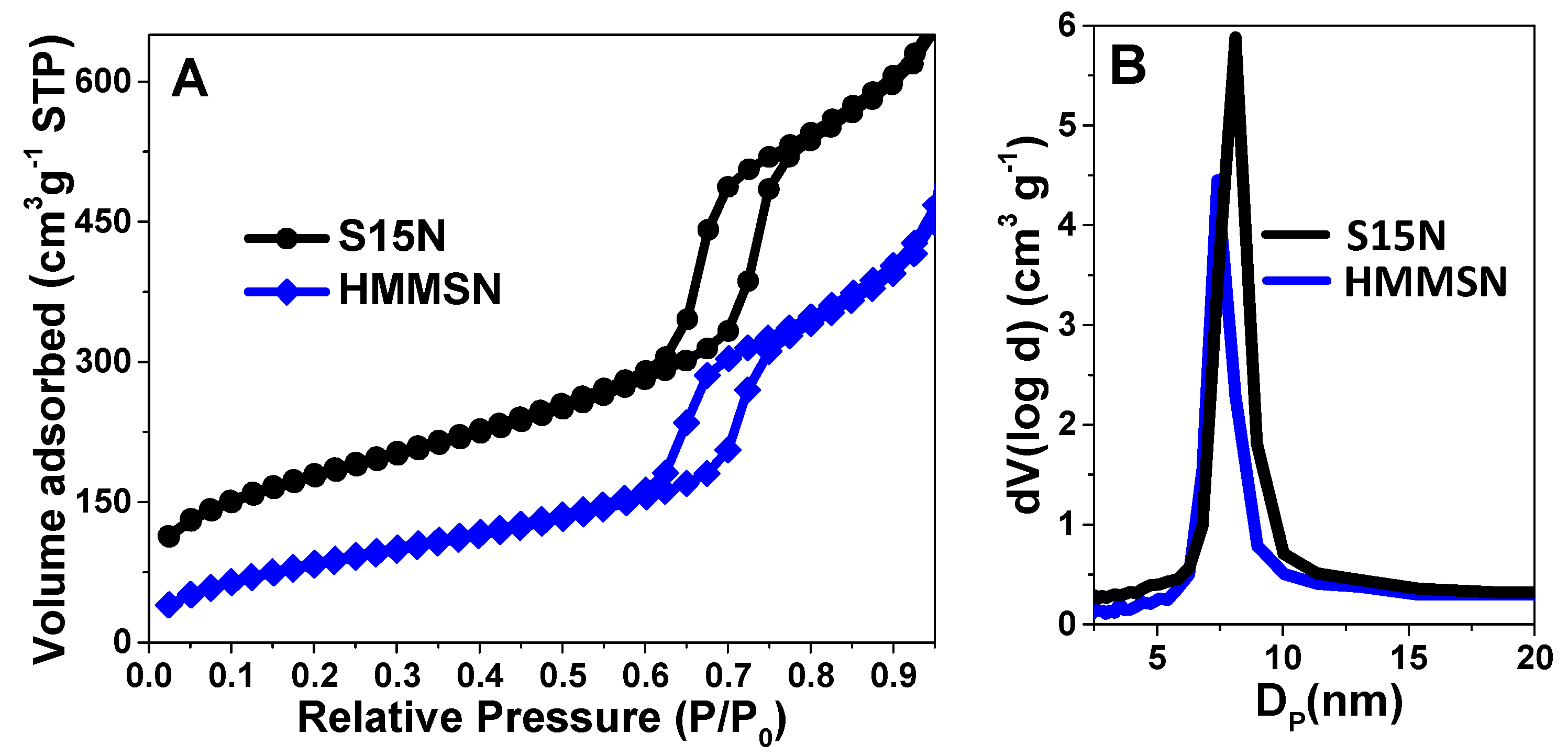
| Samples | SBET (m2 g−1) | Vp (cm3 g−1) | DBJH (nm) | d10 (nm) | a0 (nm) | twall (nm) | Wmag (%) |
|---|---|---|---|---|---|---|---|
| S15N | 617.10 | 1.78 | 8.18 | 10.52 | 12.15 | 4.03 | 0.00 |
| HMMSN | 318.97 | 1.82 | 7.40 | 10.51 | 12.14 | 4.77 | 7.60 |
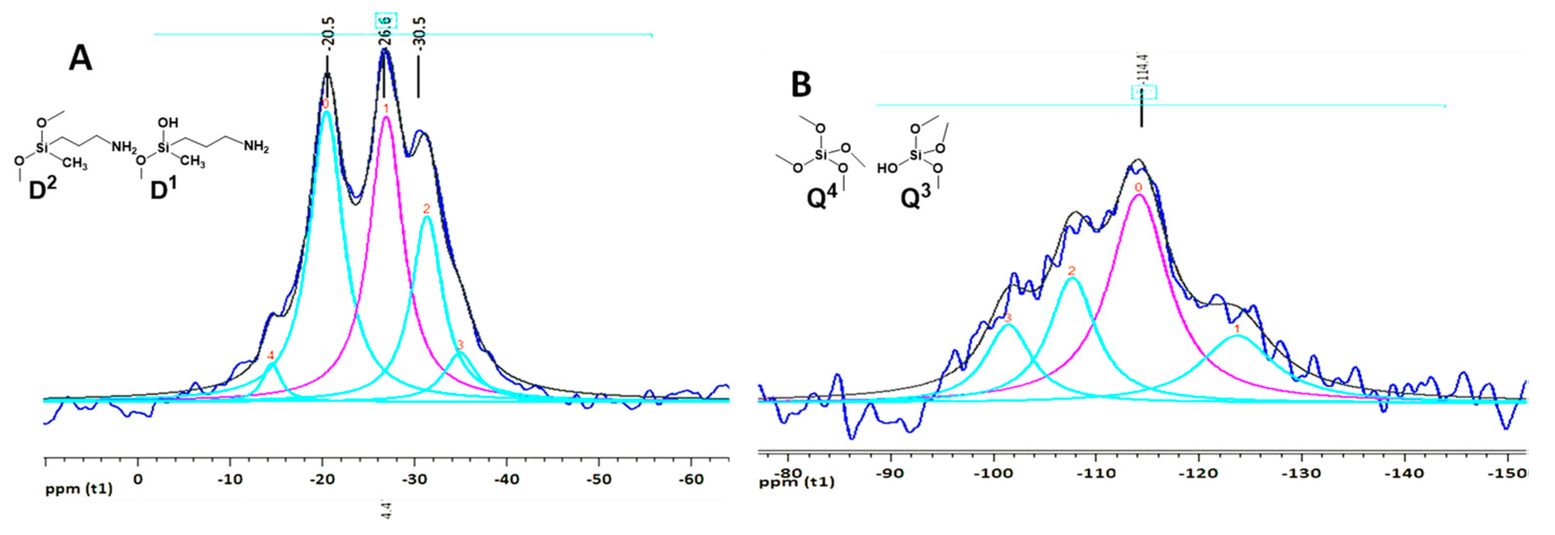
| Chemical Shift (ppm) | Silicon Environment | Area Under a Curve (%) |
|---|---|---|
| −123.80 | Q4 | 5.26 |
| −114.24 | Q4 | 12.89 |
| −107.77 | Q4 + Q3 | 6.12 |
| −101.55 | Q3 | 3.78 |
| −35.01 | D2 | 4.18 |
| −31.40 | D2 | 15.12 |
| −26.99 | D2 | 25.22 |
| −20.51 | D1 | 25.59 |
| −14.58 | D1 | 1.84 |
© 2019 by the authors. Licensee MDPI, Basel, Switzerland. This article is an open access article distributed under the terms and conditions of the Creative Commons Attribution (CC BY) license (http://creativecommons.org/licenses/by/4.0/).
Share and Cite
Vargas-Osorio, Z.; Da Silva-Candal, A.; Piñeiro, Y.; Iglesias-Rey, R.; Sobrino, T.; Campos, F.; Castillo, J.; Rivas, J. Multifunctional Superparamagnetic Stiff Nanoreservoirs for Blood Brain Barrier Applications. Nanomaterials 2019, 9, 449. https://doi.org/10.3390/nano9030449
Vargas-Osorio Z, Da Silva-Candal A, Piñeiro Y, Iglesias-Rey R, Sobrino T, Campos F, Castillo J, Rivas J. Multifunctional Superparamagnetic Stiff Nanoreservoirs for Blood Brain Barrier Applications. Nanomaterials. 2019; 9(3):449. https://doi.org/10.3390/nano9030449
Chicago/Turabian StyleVargas-Osorio, Zulema, Andrés Da Silva-Candal, Yolanda Piñeiro, Ramón Iglesias-Rey, Tomas Sobrino, Francisco Campos, José Castillo, and José Rivas. 2019. "Multifunctional Superparamagnetic Stiff Nanoreservoirs for Blood Brain Barrier Applications" Nanomaterials 9, no. 3: 449. https://doi.org/10.3390/nano9030449