Vibration and Buckling of Shear Deformable Functionally Graded Nanoporous Metal Foam Nanoshells


1
College of Aerospace Engineering, Shenyang Aerospace University, Shenyang 110136, China
2
College of Sciences, Northeastern University, Shenyang 110819, China
*
Authors to whom correspondence should be addressed.
Nanomaterials 2019, 9(2), 271; https://doi.org/10.3390/nano9020271
Submission received: 22 January 2019
/
Revised: 11 February 2019
/
Accepted: 11 February 2019
/
Published: 15 February 2019
(This article belongs to the Special Issue Functional Nanoporous Materials)
Abstract
:This article aims to investigate free vibration and buckling of functionally graded (FG) nanoporous metal foam (NPMF) nanoshells. The first-order shear deformation (FSD) shell theory is adopted and the theoretical model is formulated by using Mindlin’s most general strain gradient theory, which can derive several well-known simplified models. The symmetric and unsymmetric nanoporosity distributions are considered for the structural composition. Hamilton’s principle is employed to deduce the governing equations as well as the boundary conditions. Then, via the Navier solution technique, an analytical solution for the free vibration and buckling of FG NPMF nanoshells is presented. Afterwards, a detailed parametric analysis is conducted to highlight the effects of the nanoporosity coefficient, nanoporosity distribution, length scale parameter, and geometrical parameters on the mechanical behaviors of FG NPMF nanoshells.
1. Introduction
Functionally graded materials (FGMs) have a continuous and smooth graded distribution of material properties in the spatial field. Due to their superior properties and advantages, FGMs have been successfully extended to various engineering applications and received much attention [1,2,3,4,5,6,7,8,9,10,11,12,13,14,15,16,17,18,19,20,21,22,23,24]. Recently, a breakthrough made it possible to realize desired structural properties by adjusting the local density of structures, thereby developing novel functionally graded (FG) porous structures composed of metal foams having graded density [25,26,27,28]. The application of nanoporous metal foams (NPMFs) has been extended to some advanced engineering fields due to their extremely high specific surface area [29,30,31,32]. This kind of material has a combination of properties that is not achievable for ceramics, metals, or dense polymers.
Micro/nanostructures have been successfully used in shape memory alloys [33] and micro- and nano-electro-mechanical systems (MEMS and NEMS) [34,35]. The small-scale effects on the mechanical behaviors of micro/nanostructures have been experimentally observed in their applications [36,37]. It was revealed that the mechanical behaviors of micro/nanostructures were different from their macro counterparts due to the size effect [38,39]. Due to the lack of intrinsic material length scale parameters, the classical continuum theory has no ability to predict the mechanical characteristics of micro/nanostructures. Therefore, several size-dependent continuum theories have been proposed to compensate for the drawbacks of the classical continuum theory for micro/nanostructures. One of the size-dependent continuum theories is Mindlin’s strain gradient theory (SGT) [40], which is known as the general form of the SGT containing five additional material length scale parameters compared to the classical continuum theory. Later, several special forms of Mindlin’s SGT were proposed. For instance, one of the most popular forms is the modified strain gradient theory (MSGT) [37]. In fact, this theory is a more useful form of Mindlin’s SGT including three material length scale parameters related to symmetric rotation gradients, deviatoric stretch gradients, and dilatation gradients. Several successful applications of the MSGT in dynamic and static analyses of micro/nanobeams [41,42,43,44], plates [45,46,47], and shells [48,49,50] have been reported. It should be noticed that the modified couple stress theory (MCST) [51] can be achieved by ignoring two of the three material length scale parameters in the MSGT. Moreover, the MSGT can be simplified to the classical theory (CT) by neglecting all of the three material length scale parameters.
Recently, the structural performance of NPMF micro/nanobeams has been investigated by several researchers. Post-buckling analysis for nanobeams made of NPMFs is presented by Barati and Zenkour [52] via the nonlocal elasticity theory (NET). By using the nonlocal strain gradient theory together with the third-order shear deformation beam theory, nonlinear bending of FG NPMF micro/nanobeams reinforced by graphene platelets has been analyzed by Sahmani et al. [53]. Wang et al. [54] utilized the sinusoidal beam theory and the MSGT to study the vibration and bending of NPMF microbeams.
Shell-type structures have excellent mechanical properties [55,56,57,58,59,60,61], and thus, nanoshells are important components in various MEMS and NEMS [62,63,64]. Complete knowledge of the mechanical properties of nanoshells encourages researchers to use them more efficiently. Therefore, some research has been made to illustrate the buckling and vibration characteristics of nanoshells. For example, by using the NET, Hoseinzadeh and Khadem [65] investigated the thermoelastic vibration of double-walled carbon nanotubes (CNTs). By employing the classical shell theory together with the Gurtin-Murdoch elasticity theory, Sahmani et al. [66] analyzed the postbuckling and nonlinear buckling of cylindrical nanoshells subjected to radial and axial compressive loads. Implementing the NET in the first-order shear deformation (FSD) shell theory, Ansari et al. [67] explored the buckling behavior of multi-walled CNTs including the effect of the thermal environment. Wang et al. [68] studied the nonlinear vibration of nanoshells conveying fluid based on the surface stress elasticity theory as well as the classical shell theory.
In the present study, we aim to make an attempt to investigate the vibration and buckling of circular cylindrical nanoshells made from FG NPMFs. In order to accommodate the size dependency of the nanostructure, the general SGT is used to develop the size-dependent first-order shear deformable nanoporous nanoshell model. The governing equations, as well as the related boundary conditions, are obtained simultaneously by utilizing Hamilton’s principle. The free vibration and axial buckling of simply supported nanoporous circular cylindrical nanoshells are solved analytically by means of the Navier solution technique. Moreover, the influence of some key parameters on the vibration and buckling properties of the system is shown.
2. FG NPMF Circular Cylindrical Nanoshells
An FG NPMF circular cylindrical nanoshell of middle-surface radius R, thickness h, and length L is shown in Figure 1. Two kinds of nanoporosity distribution in the thickness direction are considered, namely, nanoporosity-1 and nanoporosity-2. Additionally, the nanoshell is subjected to axial loads .
Owing to non-uniform nanoporosity distribution, mass densities ρ(z), Young’s modulus E(z), and shear modulus μ(z) of the nanoshell are functions of position and can be written as [69,70,71,72,73,74]:
Nanoporosity-1:
Nanoporosity-2:
where ζ = z/h, the nanoporosity coefficients are and , and are the minimum and maximum values of the mass density, respectively. The minimum Young’s modulus and the maximum value are related to the minimum shear modulus and the maximum value according to , in which ν indicates Poisson’s ratio.
Thus, the relation between and is obtained as:
Figure 2 and Figure 3 give the variations of mass density and Young’s modulus, respectively, of the FG NPMF nanoshell along the thickness direction. Note that both kinds of nanoporosity distribution have the same minimum and maximum values of mass density and elasticity modulus. For the nanoporosity-1 nanoshell, it possesses the minimum values of mass density and Young’s modulus on the middle surface (z = 0) of the nanoshell; while the maximum values are on the outer (z = h/2) and inner (z = −h/2) surfaces which are equal to the values of the nanoshell that consisted of solid metal. For the nanoporosity-2, mass density and elasticity modulus have the minimum values on the inner surface and gradually increase to the maximum values on the outer surface of the shell.
3. Theory and Formulation
3.1. General SGT
As we know, the strain energy density in the CT is described as the function of the strain tensor ε. The strain energy density in Mindlin’s SGT, however, also incorporates the third-order strain gradient tensor ξ. Therefore, the strain energy density W has the most general form [40,77]:
in which ai (i = 1, 2, …, 5) are additional constants which can accommodate the small-scale effect of micro/nanostructures, and λ is Lame’s first parameter defined as [78,79]:
In Equation (9), the third-order strain gradient tensor ξ and infinitesimal strain tensor ε are defined as [40]:
in which u represents the displacement vector and ∇ is gradient operator.
The double stress tensor τijk and Cauchy stress tensor σij are written as [80]:
where δij represent the Kronecker delta.
3.2. Constitutive Relations and Strain Energy
The displacement field for the FG NPMF cylindrical nanoshell according to the FSD shell theory can be defined as [81,82,83,84,85]:
In Equation (15), ux, uy, and uz stand for the displacements of any point in the nanoshell along the x, y, and z directions, respectively; u, v, and w denote displacement components of a point at the middle surface; ψx and ψy are the rotations of the transverse normals about the y and x axes, respectively; and t denotes time.
The nonzero constituents of strain tensor ε are given by: [86,87]
where ϕ0, φ0, and k0 are the middle surface strains, ϕ1, φ1, and k1 are changes in the curvature and torsion of the middle surface, and γ1 and γ2 are the transverse shear strains. They are given by:
According to Equation (12), the following nonzero constituents of strain gradient tensor ξ are obtained:
By inserting Equations (16) and (18) into Equations (13) and (14), one can get the nonzero constituents of σ and τ as follows:
in which
Based on the general SGT, the stored strain energy, , in a linear elastic material occupying volume V can be given by [77]:
If the strain energy is symbolized by classical part and non-classical part , the total strain energy is expressed as:
in which,
In Equations (24) and (25), the non-classical and classical resultant moments and forces are expressed as follows:
where KS = 5/6 denotes the shear correction factor [88,89,90,91]; the non-classical and classical resultant moments and forces are given in Appendix A in detail.
3.3. Kinetic Energy and External Work
According to the FSD shell theory, the kinetic energy of the FG NPMF nanoshell, , is written as:
in which
Furthermore, the work carried out by axial loads can be written as:
3.4. Variational Formulation
Using Hamilton’s principle,
Inserting Equations (23), (27) and (29) into Equation (30) yields the following governing equations:
where,
Simultaneously, boundary conditions are derived as:
where nx as well as ny indicate the direction cosines of the outward unit normal to the boundary of the mid-plane.
Substituting Equation (36) into Equations (31)–(35) and considering Equation (17) and Appendix A, it yields the governing equations in terms of u, v, w, ψx, and ψy:
in which Aij, Bij, Dij, Ai, Bi, Ei, Fi, and Gi (i, j = 1, 2, …, 6) are given in Appendix B.
It is worth mentioning that the present general strain gradient nanoshell model can reduce to those of MCST, MSGT, and CT. The MSGT model can be achieved if ai (i = 1, 2, …, 5) are defined by three material length scale parameters as follows:
where l0, l1, and l2 are material length scale parameters corresponding to dilatation gradients, deviatoric stretch gradients and symmetric rotation gradients, respectively. In the following discussion, we assume that all the material length scale parameters are the same, namely, l0 = l1 = l2 = l. In addition, by setting a1 = a2 = a3 = a4 = a5 = 0, the present nanoshell model can be simplified to the CT-based model. Moreover, the MCST model [51] can be achieved if ai (i = 1, 2, …, 5) are set as:
4. Closed-Form Solution
Herein, we employ the Navier solution technique to analyze the free vibration and axial buckling behaviors of an FG NPMF cylindrical nanoshell. Navier’s method can obtain an analytical solution by introducing the double trigonometric series. Note that this method is only applicable to the simply supported boundary condition. For the other boundary conditions which are different from the simply supported boundary condition, other numerical methods such as the finite element method, differential quadrature method, finite difference method, meshless method, and wavelet method can be used. As an example, the boundary condition of the FG NPMF nanoshell considered in our study is simply supported at edges x = 0 as well as x = L, so one obtains:
The Navier procedure is used by assuming the displacements as follows:
in which , n is the circumferential wave number, and m is the axial half-wave number. Inserting Equation (50) into Equations (42)–(46) and then eliminating the trigonometric functions, the equations can be re-represented in the matrix form as:
where the displacement vector d, mass matrix M, geometric stiffness matrix Kg, and stiffness matrix K are:
in which the elements in these matrices are given in Appendix C.
If the dynamic displacement is considered, the form of the displacement vector d can be written as d = d*eiωt. Once we ignore , the eigenvalue problem of free vibrating nanoshells can be obtained as:
where ω represents the natural frequency of the FG NPMF nanoshell. The non-trivial solution requires vanishing of the determinant of the coefficient matrix in Equation (56) [92,93,94,95,96,97,98].
Buckling loads of the FG NPMF nanoshell can be obtained by neglecting the inertia term in Equation (51). Letting , one can get:
where F denotes the buckling load. For different combinations of m and n, there exists a minimum value which satisfies Equation (57). This minimum value is termed as the critical buckling load Fcr.
5. Validation
Some comparative studies are first undertaken to prove the reliability of the present analysis.
5.1. Example 1: Homogeneous Cylindrical Nanoshell Based on the MSGT
In Table 1, the present results for a homogeneous simply supported cylindrical nanoshell are compared with those obtained by Zhang et al. [99]. The parameters used are: E = 1.06TPa, ν = 0.3, ρ = 2300 kg/m3, R = 2.32 nm, and L/R = 5. The frequency parameter of the nanoshell is obtained based on the MSGT. One can see that the results from the current study coincide with those reported in Reference [99].
5.2. Example 2: Homogeneous Cylindrical Nanoshells Based on the MCST
In Table 2, the comparison study is conducted for natural frequency of a homogeneous nanoscale cylindrical shell with a simply supported boundary condition by using the MCST. The adopted material properties are: E = 1.06 TPa, ν = 0.3, ρ = 2300 kg/m3. It is observed that the obtained results have a reasonable accordance with those reported [100].
5.3. Example 3: FG Cylindrical Shell
Herein, a comparison study is conducted for a simply supported FG cylindrical shell without considering the size effect, as given in Table 3. The FG shell is made of the mixture of Stainless Steel (SS) and Nickel (Ni) with the following material parameters: ESS = 207.788 GPa, ρSS = 8166 kg/m3 and νSS = 0.317756 for SS, and ENi = 205.098 GPa, ρNi = 8900 kg/m3 and νΝI = 0.31 for Ni. Our study yields an excellent agreement with Reference [101], bespeaking the correctness of the current research.
6. Results and Discussion
In this section, size-dependent free vibration and axial buckling of an FG NPMF nanoshell simply supported at both ends are studied. The material properties of the nanoshell are , , and ν = 1/3. The dimensionless natural frequency is defined as Ω and the dimensionless buckling load is , where A110 is the specific value of A11 for the homogeneous nanoshell made of solid metal.
6.1. Free Vibration Analysis
Table 4 shows the variation of dimensionless natural frequency with the circumferential wave number for various length scale parameters. It is found that by increasing the dimensionless length scale parameter, the natural frequencies of the system decrease. Moreover, the fundamental natural frequency occurs at n = 2, independent of the length scale parameter. In the following studies, the mode (1, 2) is chosen as a representative mode.
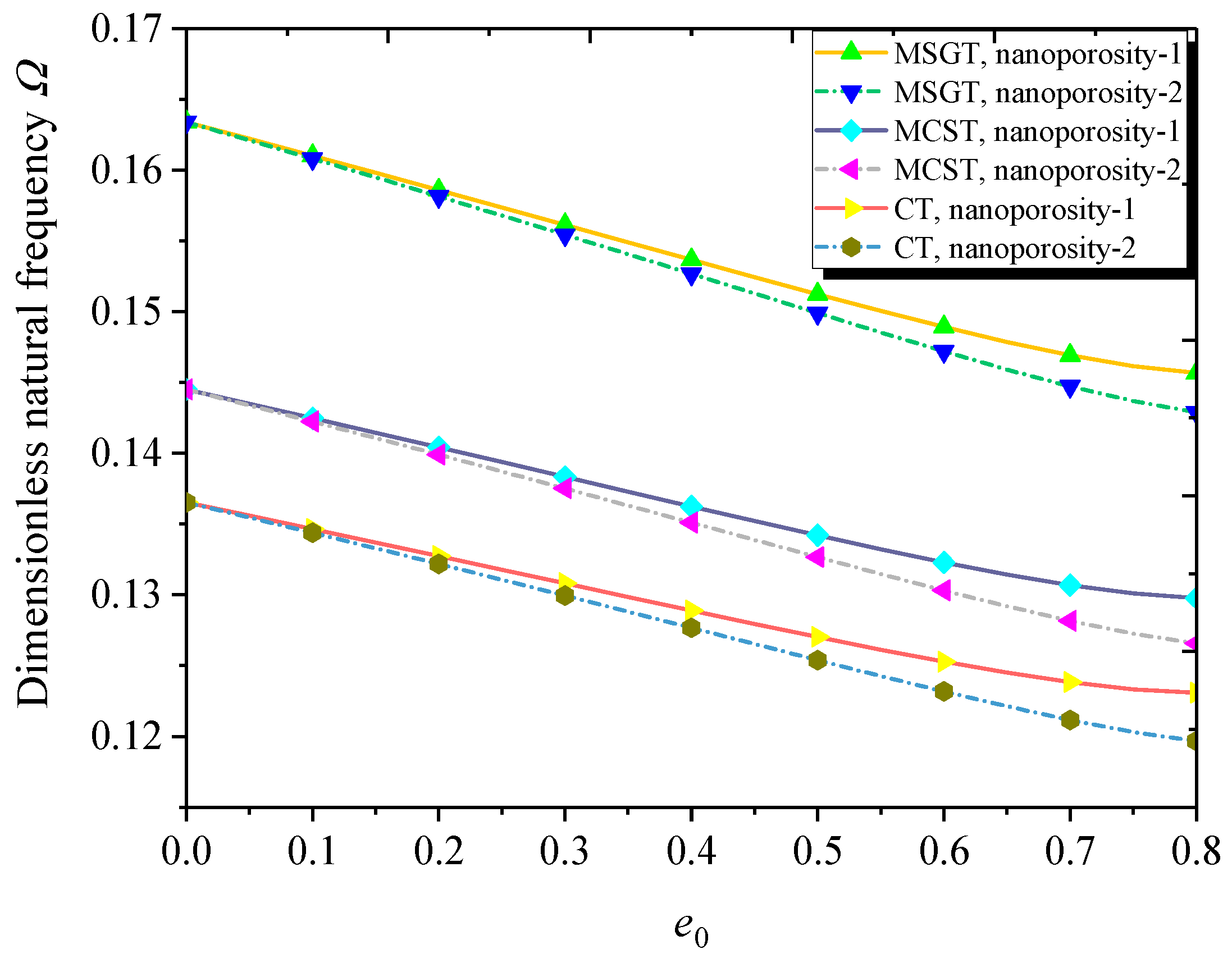
The dimensionless natural frequency versus nanoporosity coefficient for different theories and nanoporosity distributions is illustrated in Figure 4. Results show that the natural frequency decreases by increasing the nanoporosity coefficient, indicating that the nano-pores decrease the effective stiffness of the nanoshell. Furthermore, the nanoporosity-2 nanoshell has a lower natural frequency than its nanoporosity-1 counterpart. It is observed that the natural frequencies predicted by the MCST and MSGT are greater than the natural frequency predicted by the CT. In other words, the additional length scale parameter makes the FG NPMF nanoshell stiffer. This is due to the extra stiffness introduced in the MCST and MSGT.
Depicted in Figure 5 is the variation of the dimensionless natural frequency against the dimensionless length scale parameter. It is seen that the size effect on natural frequency is more pronounced when the thickness of the nanoshell is comparable to the length scale parameter. The dimensionless natural frequencies from the MCST and MSGT converge to the results from the CT for a large value of the dimensionless length scale parameter, indicating that the larger dimensionless length scale parameter diminishes the size effect on the natural frequency of the FG NPMF nanoshell.
Figure 6 plots the dimensionless natural frequency versus length-to-radius ratio with different theories and nanoporosity distributions. One can see that as the length-to-radius ratio increases, the dimensionless natural frequency decreases gradually. Compared to the MCST, the MSGT leads to more reasonable results due to the introduction of an additional deviatoric stretch gradient tensor and the dilatation gradient tensor in addition to the symmetric rotation gradient tensor.
Figure 7 illustrates the effect of the thickness-to-radius ratio on the dimensionless natural frequency of the FG NPMF nanoshell. As expected, the natural frequency of the FG NPMF nanoshell increases with the rise of thickness-to-radius. This is because the larger thickness-to-radius ratio results in the enhancement of the nanoshell stiffness. Moreover, the difference among the results obtained from the MCST, MSGT, and CT becomes more and more notable as the ratio of thickness-to-radius increases, indicating that the size effect is more significant at the larger thickness-to-radius ratio.
6.2. Buckling Analysis
The effect of the length scale parameter on the dimensionless buckling load is shown in Table 5. It is revealed that by increasing the dimensionless length scale parameter, the buckling load of the system decreases. Additionally, with the increase of circumferential wave number, the buckling load first decreases and then increases. It is noted that the critical buckling load occurs at n = 2.
Figure 8 plots the dimensionless critical buckling load versus nanoporosity coefficient for both nanoporosity distributions based on the MCST, MSGT, and CT. As can be observed, the larger nanoporosity coefficient results in a lower dimensionless critical buckling load. Moreover, the nanoporosity-1 nanoshell has a higher critical buckling load than its nanoporosity-2 counterpart. The difference between them tends to be significant with the increase of the nanoporosity coefficient. Furthermore, compared to the MCST, the MSGT leads to a more reasonable buckling load due to the introduction of an additional deviatoric stretch gradient tensor and dilatation gradient tensor in addition to the symmetric rotation gradient tensor.
Figure 9 compares the variation of the dimensionless critical buckling load with the dimensionless length scale parameter based on classical and non-classical shell models. It is noted that the critical buckling load decreases with the increasing dimensionless length scale parameter. In addition, the difference among the results from the three models (MCST, MSGT, and CT) is diminishing when the dimensionless length scale parameter tends to large, indicating that the size effect is only significant when the thickness of the nanoshell is comparable to the length scale parameter. This phenomenon was also found in microplates and microbeams [41,47,102].
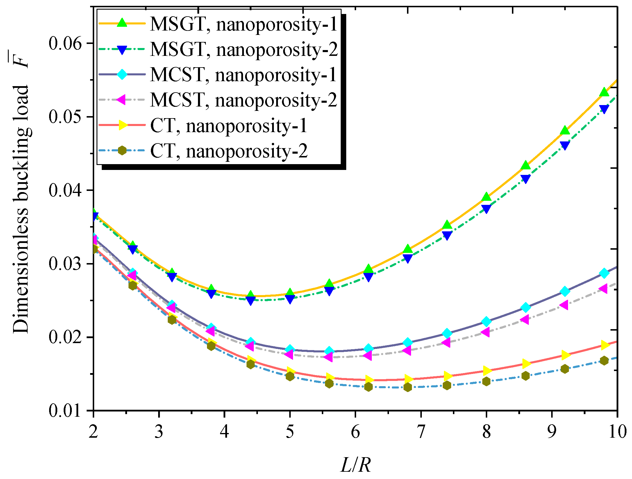
Depicted in Figure 10 is the variation of the dimensionless buckling load with the length-to-radius ratio for both kinds of nanoporosity distribution. It can be seen that with the increase of the length-to-radius ratio, the dimensionless buckling load first decreases and then increases. Moreover, the dimensionless buckling load obtained through the MSGT is greater than those predicted via the CT and MCST. The difference between the results obtained by the MCST, MSGT, and CT becomes more and more significant as the length-to-radius ratio rises.
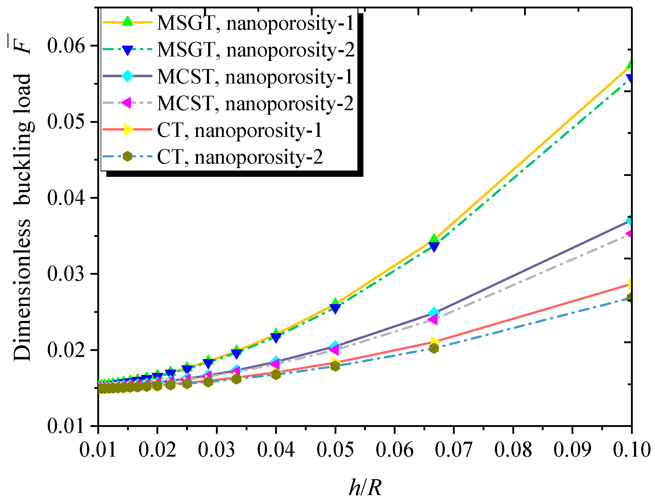
Figure 11 plots the dimensionless buckling load with respect to the thickness-to-radius ratio for both kinds of nanoporosity distribution. As can be seen, the increase in the thickness-to-radius ratio contributes to the higher buckling load of the FG NPMF nanoshell. This is due to the fact that the larger thickness-to-radius ratio enhances the stiffness of the FG NPMF nanoshell.
7. Conclusions
In this paper, size-dependent free vibration and buckling of FG NPMF cylindrical nanoshells are investigated based upon the FSD shell theory and general SGT. The symmetric and unsymmetric nanoporosity distributions are considered for the structural composition. Governing equations, as well as corresponding boundary conditions, are derived via Hamilton’s principle. Moreover, the Navier solution technique is employed to derive the analytical solutions for FG NPMF nanoshells with a simply supported boundary condition. The conclusions can be summarized as follows:
- (1)
- Nanoporosity distribution has a significant influence on the vibration and buckling characteristics of FG NPMF nanoshells. Natural frequencies and buckling loads of the nanoporosity-2 nanoshell are lower than those of the nanoporosity-1 nanoshell. As the nanoporosity coefficient increases, natural frequencies and buckling loads of the nanoshell decrease.
- (2)
- Natural frequencies of the FG NPMF nanoshells decrease with the increasing length-to-radius ratio. Additionally, the larger thickness-to-radius ratio leads to the higher natural frequency of the FG NPMF nanoshell.
- (3)
- Buckling loads decrease first and then increase with the increase of the length-to-radius ratio. Furthermore, buckling loads increase with the increasing thickness-to-radius ratio of the nanoshell.
- (4)
- When the nanoshell thickness is approximately equal to the length scale parameter, the MSGT is more appropriate than the CT and MCST for free vibration and buckling analysis of FG NPMF nanoshells.
Author Contributions
Conceptualization, Y.Z. and F.Z.; Methodology, F.Z.; Software, F.Z.; Validation, F.Z.; Formal Analysis, F.Z.; Investigation, F.Z.; Resources, Y.Z.; Data Curation, F.Z.; Writing-Original Draft Preparation, F.Z.; Writing-Review & Editing, Y.Z.; Visualization, F.Z.; Supervision, Y.Z.; Project Administration, Y.Z.; Funding Acquisition, Y.Z.
Funding
This research was funded by the National Natural Science Foundation of China (Grant no. 11672188).
Conflicts of Interest
The authors declare no conflict of interest.
Appendix A
The non-classical and classical resultant moments and forces in Equation (26) are:
Appendix B
The parameters in Equations (42)–(46) are given by:
Appendix C
The nonzero components in Equations (53)–(55) are:
References
- Wang, Y.; Ye, C.; Zu, J. Identifying the temperature effect on the vibrations of functionally graded cylindrical shells with porosities. Appl. Math. Mech. 2018, 39, 1587–1604. [Google Scholar] [CrossRef]
- Wang, Y.Q.; Zu, J.W. Nonlinear dynamics of a translational FGM plate with strong mode interaction. Int. J. Struct. Stab. Dyn. 2018, 18, 1850031. [Google Scholar] [CrossRef]
- Wang, Y.Q.; Wan, Y.H.; Zhang, Y.F. Vibrations of longitudinally traveling functionally graded material plates with porosities. Eur. J. Mech.-A/Solids 2017, 66, 55–68. [Google Scholar] [CrossRef]
- Wang, Y.Q.; Yang, Z. Nonlinear vibrations of moving functionally graded plates containing porosities and contacting with liquid: Internal resonance. Nonlinear Dyn. 2017, 90, 1461–1480. [Google Scholar] [CrossRef]
- Nejati, M.; Asanjarani, A.; Dimitri, R.; Tornabene, F. Static and free vibration analysis of functionally graded conical shells reinforced by carbon nanotubes. Int. J. Mech. Sci. 2017, 130, 383–398. [Google Scholar] [CrossRef]
- Wang, Y.Q.; Zu, J.W. Nonlinear dynamic thermoelastic response of rectangular FGM plates with longitudinal velocity. Compos. Part B Eng. 2017, 117, 74–88. [Google Scholar] [CrossRef]
- Wang, Y.Q.; Zu, J.W. Large-amplitude vibration of sigmoid functionally graded thin plates with porosities. Thin-Walled Struct. 2017, 119, 911–924. [Google Scholar] [CrossRef]
- Wang, Y.Q.; Zu, J.W. Porosity-dependent nonlinear forced vibration analysis of functionally graded piezoelectric smart material plates. Smart Mater. Struct. 2017, 26, 105014. [Google Scholar] [CrossRef]
- Wang, Y.; Zu, J. Nonlinear oscillations of sigmoid functionally graded material plates moving in longitudinal direction. Appl. Math. Mech. 2017, 38, 1533–1550. [Google Scholar] [CrossRef]
- Trinh, M.-C.; Kim, S.-E. Nonlinear thermomechanical behaviors of thin functionally graded sandwich shells with double curvature. Compos. Struct. 2018, 195, 335–348. [Google Scholar] [CrossRef]
- Wang, Y.Q.; Zu, J.W. Nonlinear dynamics of functionally graded material plates under dynamic liquid load and with longitudinal speed. Int. J. Appl. Mech. 2017, 9, 1750054. [Google Scholar] [CrossRef]
- Wang, Y.Q.; Zu, J.W. Speed-dependent nonlinear broadband vibrations of smart functionally graded piezoelectric material plates. J. Intell. Mater. Syst. Struct. 2018, 29, 1764–1776. [Google Scholar] [CrossRef]
- Wang, Y.Q.; Zu, J.W. Vibration characteristics of moving sigmoid functionally graded plates containing porosities. Int. J. Mech. Mater. Des. 2018, 14, 473–489. [Google Scholar] [CrossRef]
- Tornabene, F.; Fantuzzi, N.; Bacciocchi, M.; Viola, E. Effect of agglomeration on the natural frequencies of functionally graded carbon nanotube-reinforced laminated composite doubly-curved shells. Compos. Part B Eng. 2016, 89, 187–218. [Google Scholar] [CrossRef]
- Wang, Y.; Zu, J.W. Nonlinear dynamic behavior of inhomogeneous functional plates composed of sigmoid graded metal-ceramic materials. Sci. China Technol. Sci. 2018, 61, 1654–1665. [Google Scholar] [CrossRef]
- Fantuzzi, N.; Tornabene, F.; Bacciocchi, M.; Dimitri, R. Free vibration analysis of arbitrarily shaped Functionally Graded Carbon Nanotube-reinforced plates. Compos. Part B Eng. 2017, 115, 384–408. [Google Scholar] [CrossRef]
- Zhang, W.; Yang, J.; Hao, Y. Chaotic vibrations of an orthotropic FGM rectangular plate based on third-order shear deformation theory. Nonlinear Dyn. 2010, 59, 619–660. [Google Scholar] [CrossRef]
- Hao, Y.; Zhang, W.; Yang, J. Nonlinear dynamics of a FGM plate with two clamped opposite edges and two free edges. Acta Mech. Solida Sin. 2014, 27, 394–406. [Google Scholar] [CrossRef]
- Wang, Y.Q.; Zu, J.W. Nonlinear steady-state responses of longitudinally traveling functionally graded material plates in contact with liquid. Compos. Struct. 2017, 164, 130–144. [Google Scholar] [CrossRef]
- Zhang, W.; Hao, Y.; Guo, X.; Chen, L. Complicated nonlinear responses of a simply supported FGM rectangular plate under combined parametric and external excitations. Meccanica 2012, 47, 985–1014. [Google Scholar] [CrossRef]
- Wang, Y.Q.; Zu, J.W. Vibration behaviors of functionally graded rectangular plates with porosities and moving in thermal environment. Aerosp. Sci. Technol. 2017, 69, 550–562. [Google Scholar] [CrossRef]
- Zhang, W.; Hao, Y.; Yang, J. Nonlinear dynamics of FGM circular cylindrical shell with clamped–clamped edges. Compos. Struct. 2012, 94, 1075–1086. [Google Scholar] [CrossRef]
- Wang, Y.Q. Electro-mechanical vibration analysis of functionally graded piezoelectric porous plates in the translation state. Acta Astronaut. 2018, 143, 263–271. [Google Scholar] [CrossRef]
- Wang, Y.Q.; Wan, Y.H.; Zu, J.W. Nonlinear dynamic characteristics of functionally graded sandwich thin nanoshells conveying fluid incorporating surface stress influence. Thin-Walled Struct. 2019, 135, 537–547. [Google Scholar] [CrossRef]
- Hassani, A.; Habibolahzadeh, A.; Bafti, H. Production of graded aluminum foams via powder space holder technique. Mater. Des. 2012, 40, 510–515. [Google Scholar] [CrossRef]
- He, S.Y.; Zhang, Y.; Dai, G.; Jiang, J.Q. Preparation of density-graded aluminum foam. Mater. Sci. Eng. A 2014, 618, 496–499. [Google Scholar] [CrossRef]
- Hangai, Y.; Takahashi, K.; Utsunomiya, T.; Kitahara, S.; Kuwazuru, O.; Yoshikawa, N. Fabrication of functionally graded aluminum foam using aluminum alloy die castings by friction stir processing. Mater. Sci. Eng. A 2012, 534, 716–719. [Google Scholar] [CrossRef]
- Hangai, Y.; Saito, K.; Utsunomiya, T.; Kitahara, S.; Kuwazuru, O.; Yoshikawa, N. Compression properties of Al/Al–Si–Cu alloy functionally graded aluminum foam fabricated by friction stir processing route. Mater. Trans. 2013, 54, 405–408. [Google Scholar] [CrossRef]
- Pia, G.; Delogu, F. On the elastic deformation behavior of nanoporous metal foams. Scr. Mater. 2013, 69, 781–784. [Google Scholar] [CrossRef]
- Park, H.; Ahn, C.; Jo, H.; Choi, M.; Kim, D.S.; Kim, D.K.; Jeon, S.; Choe, H. Large-area metal foams with highly ordered sub-micrometer-scale pores for potential applications in energy areas. Mater. Lett. 2014, 129, 174–177. [Google Scholar] [CrossRef]
- Heydari, H.; Moosavifard, S.E.; Shahraki, M.; Elyasi, S. Facile synthesis of nanoporous CuS nanospheres for high-performance supercapacitor electrodes. J. Energy Chem. 2017, 26, 762–767. [Google Scholar] [CrossRef]
- Li, J.; Wang, S.; Xiao, T.; Tan, X.; Xiang, P.; Jiang, L.; Deng, C.; Li, W.; Li, M. Controllable preparation of nanoporous Ni3S2 films by sulfuration of nickel foam as promising asymmetric supercapacitor electrodes. Appl. Surf. Sci. 2017, 420, 919–926. [Google Scholar] [CrossRef]
- Fu, Y.; Du, H.; Zhang, S. Functionally graded TiN/TiNi shape memory alloy films. Mater. Lett. 2003, 57, 2995–2999. [Google Scholar] [CrossRef]
- Li, X.; Bhushan, B.; Takashima, K.; Baek, C.-W.; Kim, Y.-K. Mechanical characterization of micro/nanoscale structures for MEMS/NEMS applications using nanoindentation techniques. Ultramicroscopy 2003, 97, 481–494. [Google Scholar] [CrossRef]
- Moser, Y.; Gijs, M.A. Miniaturized flexible temperature sensor. J. Microelectromech. Syst. 2007, 16, 1349–1354. [Google Scholar] [CrossRef]
- Fleck, N.; Muller, G.; Ashby, M.; Hutchinson, J. Strain gradient plasticity: Theory and experiment. Acta Metall. Mater. 1994, 42, 475–487. [Google Scholar] [CrossRef]
- Lam, D.C.; Yang, F.; Chong, A.; Wang, J.; Tong, P. Experiments and theory in strain gradient elasticity. J. Mech. Phys. Solids 2003, 51, 1477–1508. [Google Scholar] [CrossRef]
- Miller, R.E.; Shenoy, V.B. Size-dependent elastic properties of nanosized structural elements. Nanotechnology 2000, 11, 139. [Google Scholar] [CrossRef]
- Xu, F.; Qin, Q.; Mishra, A.; Gu, Y.; Zhu, Y. Mechanical properties of ZnO nanowires under different loading modes. Nano Res. 2010, 3, 271–280. [Google Scholar] [CrossRef]
- Mindlin, R.D.; Eshel, N. On first strain-gradient theories in linear elasticity. Int. J. Solids Struct. 1968, 4, 109–124. [Google Scholar] [CrossRef]
- Wang, B.; Zhao, J.; Zhou, S. A micro scale Timoshenko beam model based on strain gradient elasticity theory. Eur. J. Mech.-A/Solids 2010, 29, 591–599. [Google Scholar] [CrossRef]
- Ansari, R.; Gholami, R.; Faghih Shojaei, M.; Mohammadi, V.; Sahmani, S. Size-dependent bending, buckling and free vibration of functionally graded Timoshenko microbeams based on the most general strain gradient theory. Compos. Struct. 2013, 100, 385–397. [Google Scholar] [CrossRef]
- Kong, S.; Zhou, S.; Nie, Z.; Wang, K. Static and dynamic analysis of micro beams based on strain gradient elasticity theory. Int. J. Eng. Sci. 2009, 47, 487–498. [Google Scholar] [CrossRef]
- Akgöz, B.; Civalek, Ö. Analysis of micro-sized beams for various boundary conditions based on the strain gradient elasticity theory. Arch. Appl. Mech. 2012, 82, 423–443. [Google Scholar] [CrossRef]
- Wang, B.; Zhou, S.; Zhao, J.; Chen, X. A size-dependent Kirchhoff micro-plate model based on strain gradient elasticity theory. Eur. J. Mech.-A/Solids 2011, 30, 517–524. [Google Scholar] [CrossRef]
- Movassagh, A.A.; Mahmoodi, M. A micro-scale modeling of Kirchhoff plate based on modified strain-gradient elasticity theory. Eur. J. Mech.-A/Solids 2013, 40, 50–59. [Google Scholar] [CrossRef]
- Akgöz, B.; Civalek, Ö. A microstructure-dependent sinusoidal plate model based on the strain gradient elasticity theory. Acta Mech. 2015, 226, 2277–2294. [Google Scholar] [CrossRef]
- Zeighampour, H.; Beni, Y.T. Cylindrical thin-shell model based on modified strain gradient theory. Int. J. Eng. Sci. 2014, 78, 27–47. [Google Scholar] [CrossRef]
- Ansari, R.; Gholami, R.; Norouzzadeh, A. Size-dependent thermo-mechanical vibration and instability of conveying fluid functionally graded nanoshells based on Mindlin’s strain gradient theory. Thin-Walled Struct. 2016, 105, 172–184. [Google Scholar] [CrossRef]
- Zeighampour, H.; Beni, Y.T.; Karimipour, I. Torsional vibration and static analysis of the cylindrical shell based on strain gradient theory. Arabian J. Sci. Eng. 2016, 41, 1713–1722. [Google Scholar] [CrossRef]
- Yang, F.; Chong, A.; Lam, D.C.C.; Tong, P. Couple stress based strain gradient theory for elasticity. Int. J. Solids Struct. 2002, 39, 2731–2743. [Google Scholar] [CrossRef]
- Barati, M.R.; Zenkour, A.M. Investigating post-buckling of geometrically imperfect metal foam nanobeams with symmetric and asymmetric porosity distributions. Compos. Struct. 2017, 182, 91–98. [Google Scholar] [CrossRef]
- Sahmani, S.; Aghdam, M.M.; Rabczuk, T. Nonlinear bending of functionally graded porous micro/nano-beams reinforced with graphene platelets based upon nonlocal strain gradient theory. Compos. Struct. 2018, 186, 68–78. [Google Scholar] [CrossRef]
- Wang, Y.Q.; Zhao, H.L.; Ye, C.; Zu, J.W. A Porous Microbeam Model for Bending and Vibration Analysis Based on the Sinusoidal Beam Theory and Modified Strain Gradient Theory. Int. J. Appl. Mech. 2018, 10, 1850059. [Google Scholar] [CrossRef]
- Wang, Y.; Guo, X.; Chang, H.; Li, H. Nonlinear dynamic response of rotating circular cylindrical shells with precession of vibrating shape—Part I: Numerical solution. Int. J. Mech. Sci. 2010, 52, 1217–1224. [Google Scholar] [CrossRef]
- Wang, Y.; Guo, X.; Chang, H.; Li, H. Nonlinear dynamic response of rotating circular cylindrical shells with precession of vibrating shape—Part II: Approximate analytical solution. Int. J. Mech. Sci. 2010, 52, 1208–1216. [Google Scholar] [CrossRef]
- Wang, Y.Q.; Liang, L.; Guo, X.H. Internal resonance of axially moving laminated circular cylindrical shells. J. Sound Vib. 2013, 332, 6434–6450. [Google Scholar] [CrossRef]
- Wang, Y.Q. Nonlinear vibration of a rotating laminated composite circular cylindrical shell: Traveling wave vibration. Nonlinear Dyn. 2014, 77, 1693–1707. [Google Scholar] [CrossRef]
- Wang, Y.; Guo, X.; Li, Y.; Li, J. Nonlinear traveling wave vibration of a circular cylindrical shell subjected to a moving concentrated harmonic force. J. Sound Vib. 2010, 329, 338–352. [Google Scholar] [CrossRef]
- Wang, Y.; Liang, L.; Guo, X.; Li, J.; Liu, J.; Liu, P. Nonlinear vibration response and bifurcation of circular cylindrical shells under traveling concentrated harmonic excitation. Acta Mech. Solida Sin. 2013, 26, 277–291. [Google Scholar] [CrossRef]
- Nejati, M.; Dimitri, R.; Tornabene, F.; Hossein Yas, M. Thermal buckling of nanocomposite stiffened cylindrical shells reinforced by functionally graded wavy carbon nanotubes with temperature-dependent properties. Appl. Sci. 2017, 7, 1223. [Google Scholar] [CrossRef]
- Baughman, R.H.; Cui, C.; Zakhidov, A.A.; Iqbal, Z.; Barisci, J.N.; Spinks, G.M.; Wallace, G.G.; Mazzoldi, A.; De Rossi, D.; Rinzler, A.G. Carbon nanotube actuators. Science 1999, 284, 1340–1344. [Google Scholar] [CrossRef] [PubMed]
- Wu, G.; Hu, Y.; Zhao, J.; Lan, T.; Wang, D.; Liu, Y.; Chen, W. Ordered and Active Nanochannel Electrode Design for High-Performance Electrochemical Actuator. Small 2016, 12, 4986–4992. [Google Scholar] [CrossRef] [PubMed]
- Raschke, G.; Brogl, S.; Susha, A.; Rogach, A.; Klar, T.; Feldmann, J.; Fieres, B.; Petkov, N.; Bein, T.; Nichtl, A. Gold nanoshells improve single nanoparticle molecular sensors. Nano Lett. 2004, 4, 1853–1857. [Google Scholar] [CrossRef]
- Hoseinzadeh, M.; Khadem, S. A nonlocal shell theory model for evaluation of thermoelastic damping in the vibration of a double-walled carbon nanotube. Phys. E Low-Dimens. Syst. Nanostruct. 2014, 57, 6–11. [Google Scholar] [CrossRef]
- Sahmani, S.; Aghdam, M.; Bahrami, M. Nonlinear buckling and postbuckling behavior of cylindrical nanoshells subjected to combined axial and radial compressions incorporating surface stress effects. Compos. Part B Eng. 2015, 79, 676–691. [Google Scholar] [CrossRef]
- Ansari, R.; Rouhi, H.; Sahmani, S. Thermal effect on axial buckling behavior of multi-walled carbon nanotubes based on nonlocal shell model. Phys. E Low-Dimens. Syst. Nanostruct. 2011, 44, 373–378. [Google Scholar] [CrossRef]
- Wang, Y.Q.; Li, H.; Zhang, Y.; Zu, J.W. A nonlinear surface-stress-dependent model for vibration analysis of cylindrical nanoscale shells conveying fluid. Appl. Math. Model. 2018, 64, 55–70. [Google Scholar] [CrossRef]
- Magnucki, K.; Stasiewicz, P. Elastic buckling of a porous beam. J. Theor. Appl. Mech. 2004, 42, 859–868. [Google Scholar]
- Jabbari, M.; Mojahedin, A.; Khorshidvand, A.; Eslami, M. Buckling analysis of a functionally graded thin circular plate made of saturated porous materials. J. Eng. Mech. 2013, 140, 287–295. [Google Scholar] [CrossRef]
- Wang, Y.Q.; Liang, C. Wave propagation characteristics in nanoporous metal foam nanobeams. Results Phys. 2019, 12, 287–297. [Google Scholar] [CrossRef]
- Wang, Y.Q.; Liang, C.; Zu, J.W. Examining wave propagation characteristics in metal foam beams: Euler–Bernoulli and Timoshenko models. J. Braz. Soc. Mech. Sci. Eng. 2018, 40, 565. [Google Scholar] [CrossRef]
- Wang, Y.; Zhang, Z. Non-local buckling analysis of functionally graded nanoporous metal foam nanoplates. Coatings 2018, 8, 389. [Google Scholar] [CrossRef]
- Wang, Y.Q.; Ye, C.; Zu, J.W. Nonlinear vibration of metal foam cylindrical shells reinforced with graphene platelets. Aerosp. Sci. Technol. 2019, 85, 359–370. [Google Scholar] [CrossRef]
- Chen, D.; Yang, J.; Kitipornchai, S. Elastic buckling and static bending of shear deformable functionally graded porous beam. Compos. Struct. 2015, 133, 54–61. [Google Scholar] [CrossRef]
- Chen, D.; Yang, J.; Kitipornchai, S. Free and forced vibrations of shear deformable functionally graded porous beams. Int. J. Mech. Sci. 2016, 108, 14–22. [Google Scholar] [CrossRef]
- Fleck, N.; Hutchinson, J. Strain gradient plasticity. Adv. Appl. Mech. 1997, 33, 296–361. [Google Scholar]
- Rahim, M.Z.; Ding, S.; Hu, B.; Mo, J. Crater size prediction in electrical discharge grinding (EDG) of polycrystalline diamond (PCD). Nonconv. Technol. Rev./Revista de Tehnologii Neconventionale 2014, 18, 92–97. [Google Scholar]
- Rezaiee-Pajand, M.; Pourhekmat, D.; Arabi, E. Thermo-mechanical stability analysis of functionally graded shells. Eng. Struct. 2019, 178, 1–11. [Google Scholar] [CrossRef]
- Mindlin, R.D. Micro-structure in linear elasticity. Arch. Ration. Mech. Anal. 1964, 16, 51–78. [Google Scholar] [CrossRef]
- Amabili, M. Nonlinear Vibrations and Stability of Shells and Plates; Cambridge University Press: Cambridge, UK, 2008. [Google Scholar]
- Leissa, A.W. Vibration of Shells; Scientific and Technical Information Office, National Aeronautics and Space Administration: Washington, DC, USA, 1973.
- Kamarian, S.; Salim, M.; Dimitri, R.; Tornabene, F. Free vibration analysis of conical shells reinforced with agglomerated Carbon Nanotubes. Int. J. Mech. Sci. 2016, 108, 157–165. [Google Scholar] [CrossRef]
- Kiani, Y.; Dimitri, R.; Tornabene, F. Free vibration study of composite conical panels reinforced with FG-CNTs. Polym. Compos. 2018, 172, 472–482. [Google Scholar] [CrossRef]
- Tornabene, F.; Bacciocchi, M.; Fantuzzi, N.; Reddy, J. Multiscale approach for three-phase CNT/polymer/fiber laminated nanocomposite structures. Polym. Compos. 2017. [Google Scholar] [CrossRef]
- Reddy, J.N. Mechanics of Laminated Composite Plates and Shells: Theory and Analysis; CRC Press: Boca Raton, FL, USA, 2004. [Google Scholar]
- Christoforou, A.; Swanson, S. Analysis of simply-supported orthotropic cylindrical shells subject to lateral impact loads. J. Appl. Mech. 1990, 57, 376–382. [Google Scholar] [CrossRef]
- Thai, H.-T.; Choi, D.-H. A simple first-order shear deformation theory for the bending and free vibration analysis of functionally graded plates. Compos. Struct. 2013, 101, 332–340. [Google Scholar] [CrossRef]
- Whitney, J.; Pagano, N. Shear deformation in heterogeneous anisotropic plates. J. Appl. Mech. 1970, 37, 1031–1036. [Google Scholar] [CrossRef]
- Kiani, Y.; Shakeri, M.; Eslami, M. Thermoelastic free vibration and dynamic behaviour of an FGM doubly curved panel via the analytical hybrid Laplace–Fourier transformation. Acta Mech. 2012, 223, 1199–1218. [Google Scholar] [CrossRef]
- Ke, L.-L.; Wang, Y.-S.; Yang, J.; Kitipornchai, S. Nonlinear free vibration of size-dependent functionally graded microbeams. Int. J. Eng. Sci. 2012, 50, 256–267. [Google Scholar] [CrossRef]
- Wang, Y.Q.; Huang, X.B.; Li, J. Hydroelastic dynamic analysis of axially moving plates in continuous hot-dip galvanizing process. Int. J. Mech. Sci. 2016, 110, 201–216. [Google Scholar] [CrossRef]
- Wang, Y.Q.; Liu, Y.F.; Zu, J.W. Analytical treatment of nonlocal vibration of multilayer functionally graded piezoelectric nanoscale shells incorporating thermal and electrical effect. Eur. Phys. J. Plus 2019, 134, 54. [Google Scholar] [CrossRef]
- Wang, Y.; Zu, J. Analytical analysis for vibration of longitudinally moving plate submerged in infinite liquid domain. Appl. Math. Mech. 2017, 38, 625–646. [Google Scholar] [CrossRef]
- Wang, Y.Q.; Zu, J.W. Instability of viscoelastic plates with longitudinally variable speed and immersed in ideal liquid. Int. J. Appl. Mech. 2017, 9, 1750005. [Google Scholar] [CrossRef]
- Wang, Y.; Du, W.; Huang, X.; Xue, S. Study on the dynamic behavior of axially moving rectangular plates partially submersed in fluid. Acta Mech. Solida Sin. 2015, 28, 706–721. [Google Scholar] [CrossRef]
- Wang, Y.Q.; Xue, S.W.; Huang, X.B.; Du, W. Vibrations of axially moving vertical rectangular plates in contact with fluid. Int. J. Struct. Stab. Dyn. 2016, 16, 1450092. [Google Scholar] [CrossRef]
- Wang, Y.Q.; Guo, X.H.; Sun, Z.; Li, J. Stability and dynamics of axially moving unidirectional plates partially immersed in a liquid. Int. J. Struct. Stab. Dyn. 2014, 14, 1450010. [Google Scholar] [CrossRef]
- Zhang, B.; He, Y.; Liu, D.; Shen, L.; Lei, J. Free vibration analysis of four-unknown shear deformable functionally graded cylindrical microshells based on the strain gradient elasticity theory. Compos. Struct. 2015, 119, 578–597. [Google Scholar] [CrossRef]
- Ghadiri, M.; SafarPour, H. Free vibration analysis of size-dependent functionally graded porous cylindrical microshells in thermal environment. J. Therm. Stress. 2017, 40, 55–71. [Google Scholar] [CrossRef]
- Loy, C.; Lam, K.; Reddy, J. Vibration of functionally graded cylindrical shells. Int. J. Mech. Sci. 1999, 41, 309–324. [Google Scholar] [CrossRef]
- Sahmani, S.; Ansari, R. On the free vibration response of functionally graded higher-order shear deformable microplates based on the strain gradient elasticity theory. Compos. Struct. 2013, 95, 430–442. [Google Scholar] [CrossRef]
Figure 1.
Schematic of a functionally graded (FG) nanoporous metal foam (NPMF) cylindrical nanoshell. (a) Coordinate system; (b) nanoporosity-1; (c) nanoporosity-2.
Figure 1.
Schematic of a functionally graded (FG) nanoporous metal foam (NPMF) cylindrical nanoshell. (a) Coordinate system; (b) nanoporosity-1; (c) nanoporosity-2.
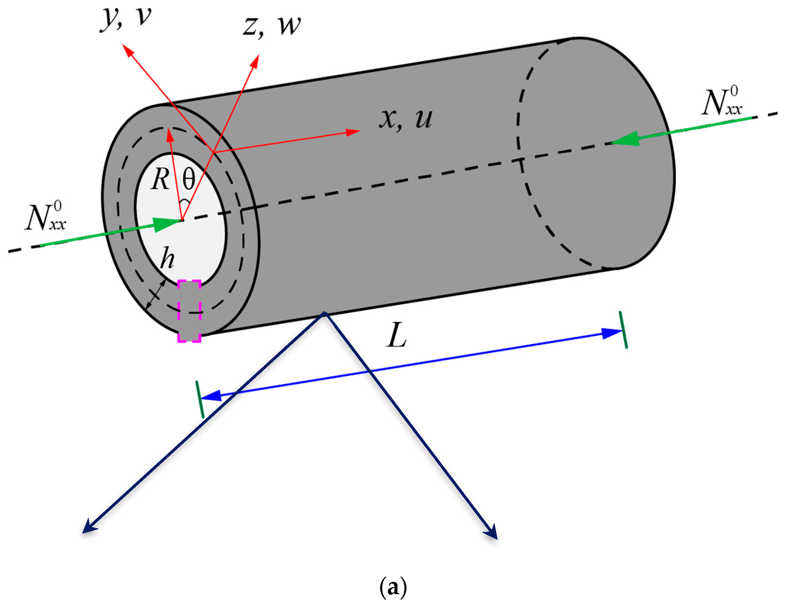

Figure 2.
Variation of mass density of FG NPMF nanoshell: (a) nanoporosity-1; (b) nanoporosity-2.
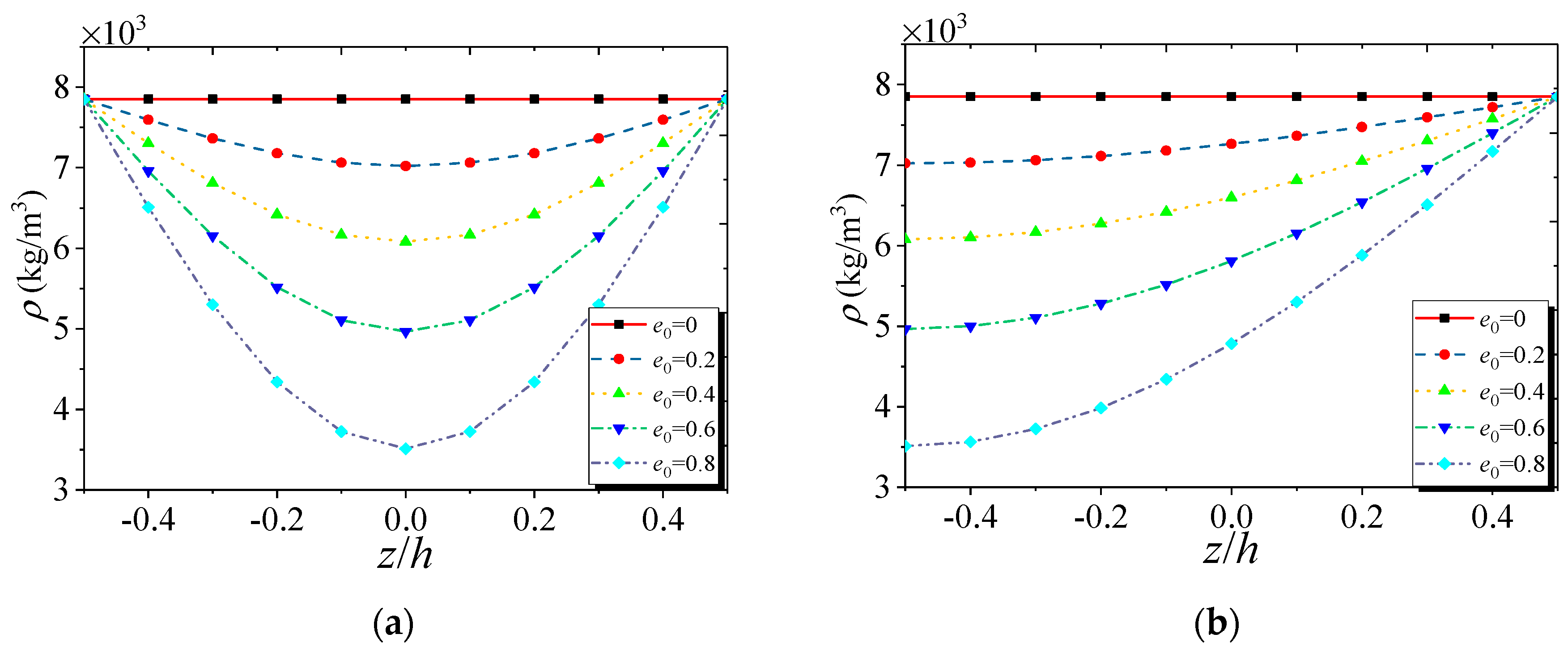
Figure 3.
Variation of Young’s modulus of FG NPMF nanoshell: (a) nanoporosity-1; (b) nanoporosity-2.
Figure 3.
Variation of Young’s modulus of FG NPMF nanoshell: (a) nanoporosity-1; (b) nanoporosity-2.
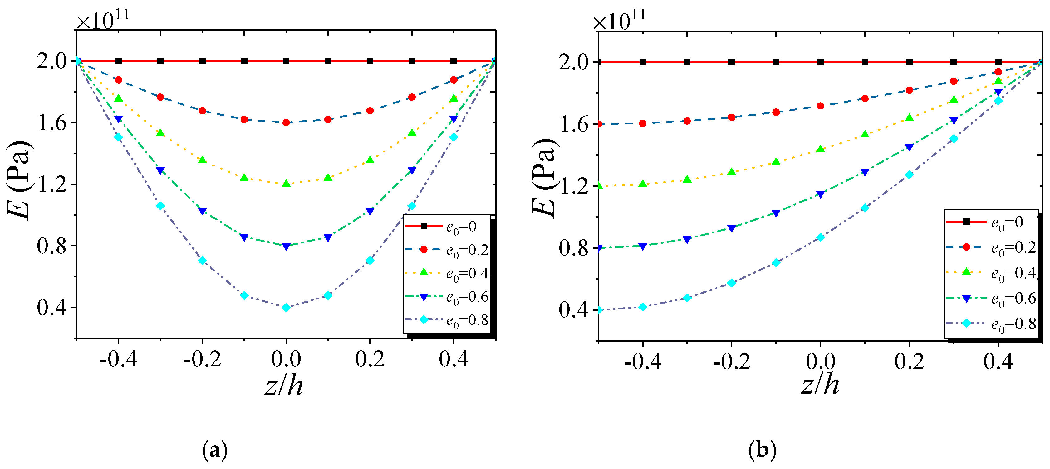
Figure 4.
Dimensionless natural frequency versus nanoporosity coefficient with different theories and nanoporosity distributions (m = 1, n = 2, h = 10 nm, R = 20 h, h = 2l, L = 4R).
Figure 4.
Dimensionless natural frequency versus nanoporosity coefficient with different theories and nanoporosity distributions (m = 1, n = 2, h = 10 nm, R = 20 h, h = 2l, L = 4R).

Figure 5.
Dimensionless natural frequency versus dimensionless length scale parameter with different theories and nanoporosity distributions (m = 1, n = 2, h = 10 nm, R = 20 h, L = 4R, e0 = 0.5).
Figure 5.
Dimensionless natural frequency versus dimensionless length scale parameter with different theories and nanoporosity distributions (m = 1, n = 2, h = 10 nm, R = 20 h, L = 4R, e0 = 0.5).
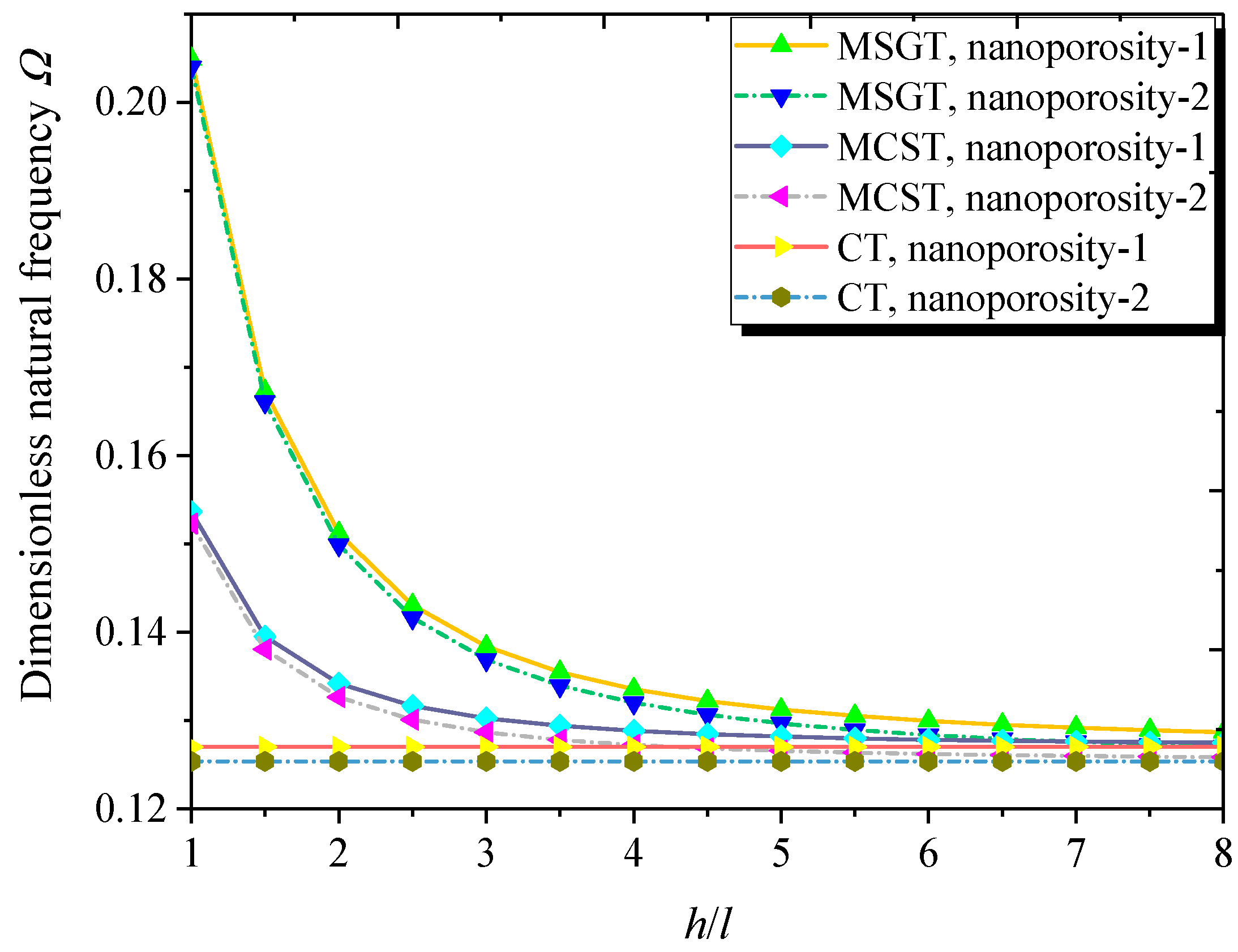
Figure 6.
Dimensionless natural frequency versus length-to-radius ratio with different theories and nanoporosity distributions (m = 1, n = 2, h = 10 nm, R = 20 h, h = 2l, e0 = 0.5).
Figure 6.
Dimensionless natural frequency versus length-to-radius ratio with different theories and nanoporosity distributions (m = 1, n = 2, h = 10 nm, R = 20 h, h = 2l, e0 = 0.5).
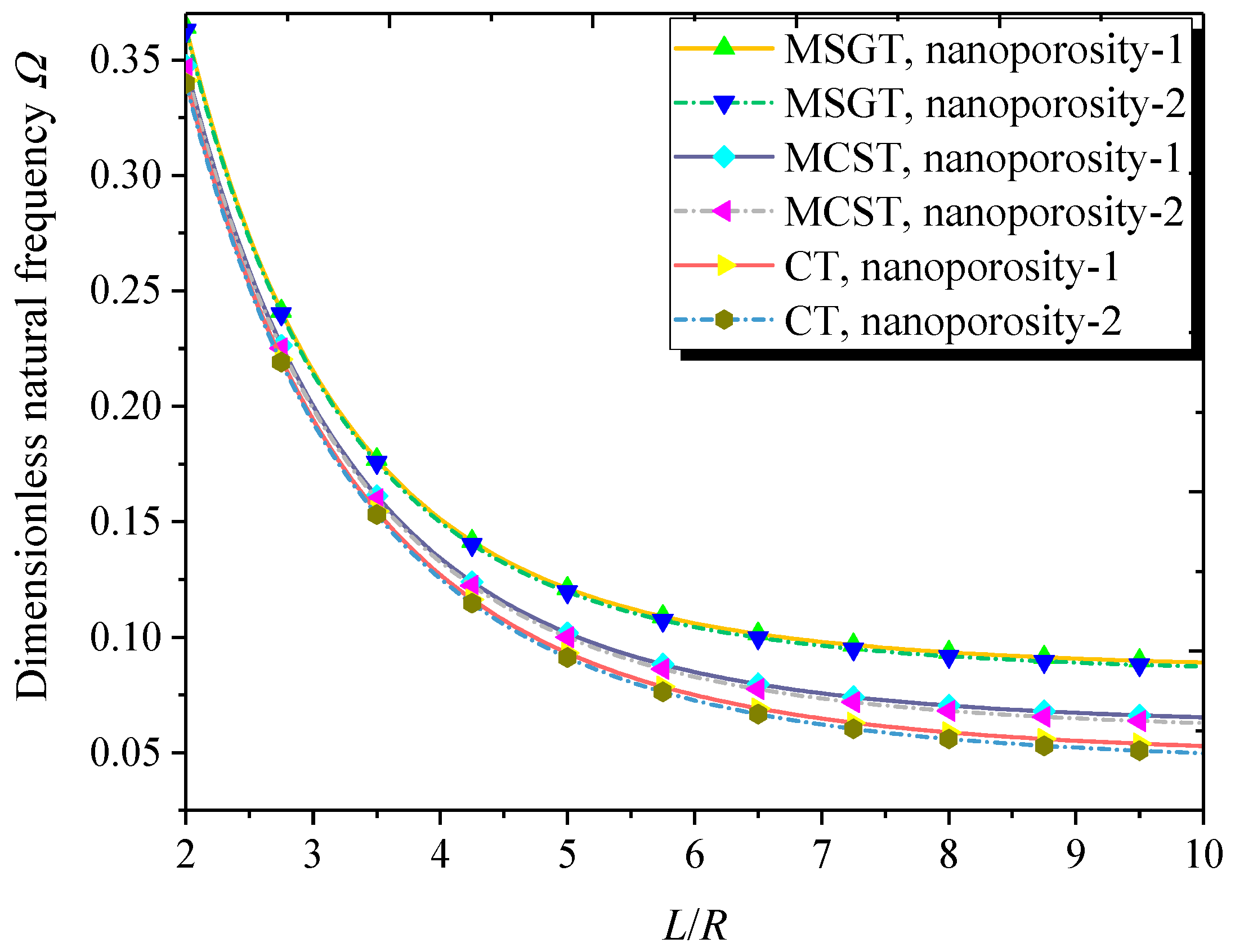
Figure 7.
Dimensionless natural frequency versus thickness-to-radius ratio with different theories and nanoporosity distributions (m = 1, n = 2, h = 10 nm, L = 4R, h = 2l, e0 = 0.5).
Figure 7.
Dimensionless natural frequency versus thickness-to-radius ratio with different theories and nanoporosity distributions (m = 1, n = 2, h = 10 nm, L = 4R, h = 2l, e0 = 0.5).
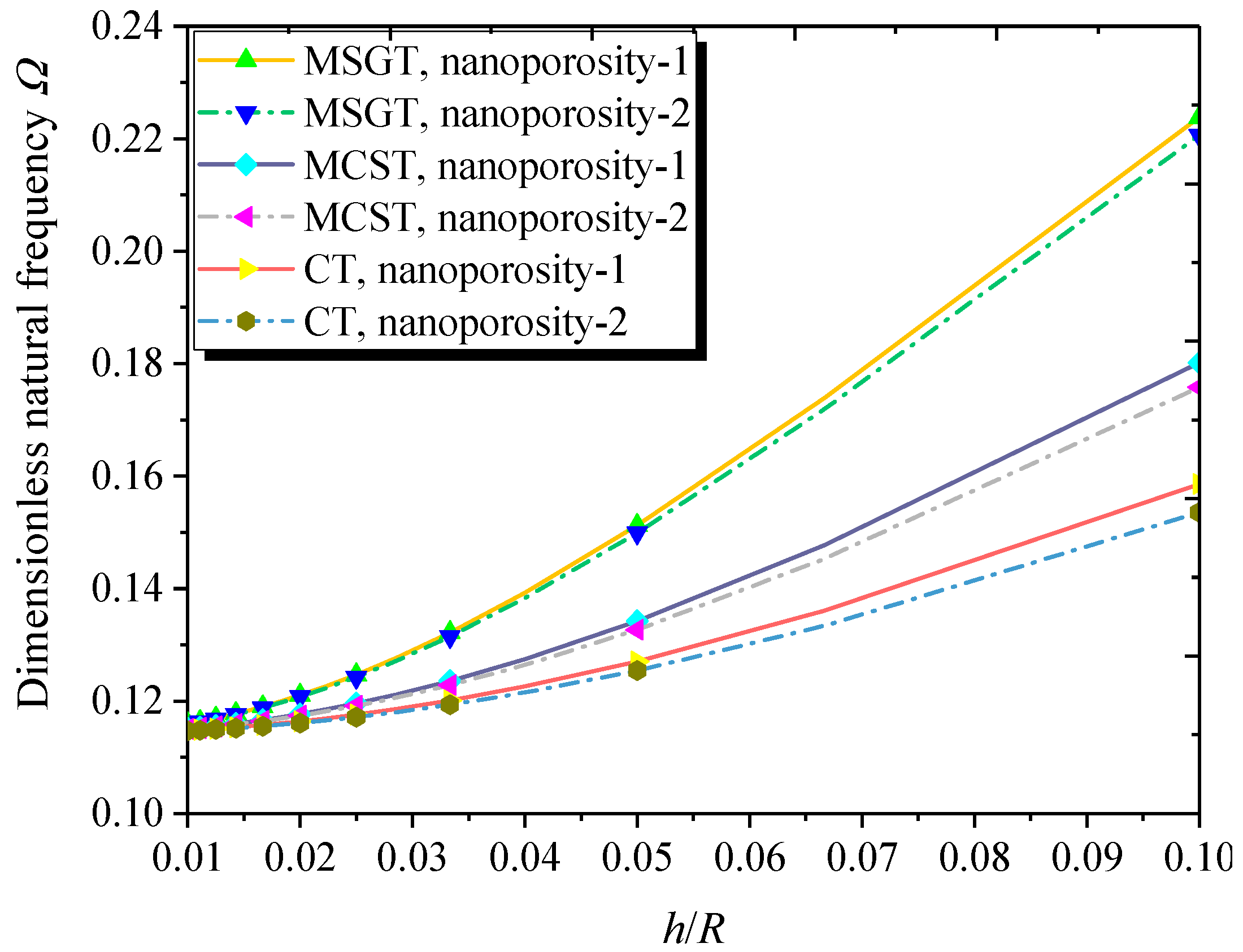
Figure 8.
Dimensionless critical buckling load versus nanoporosity coefficient (m = 1, n = 2, h = 10 nm, R = 20 h, L = 4R, h = 2l).
Figure 8.
Dimensionless critical buckling load versus nanoporosity coefficient (m = 1, n = 2, h = 10 nm, R = 20 h, L = 4R, h = 2l).
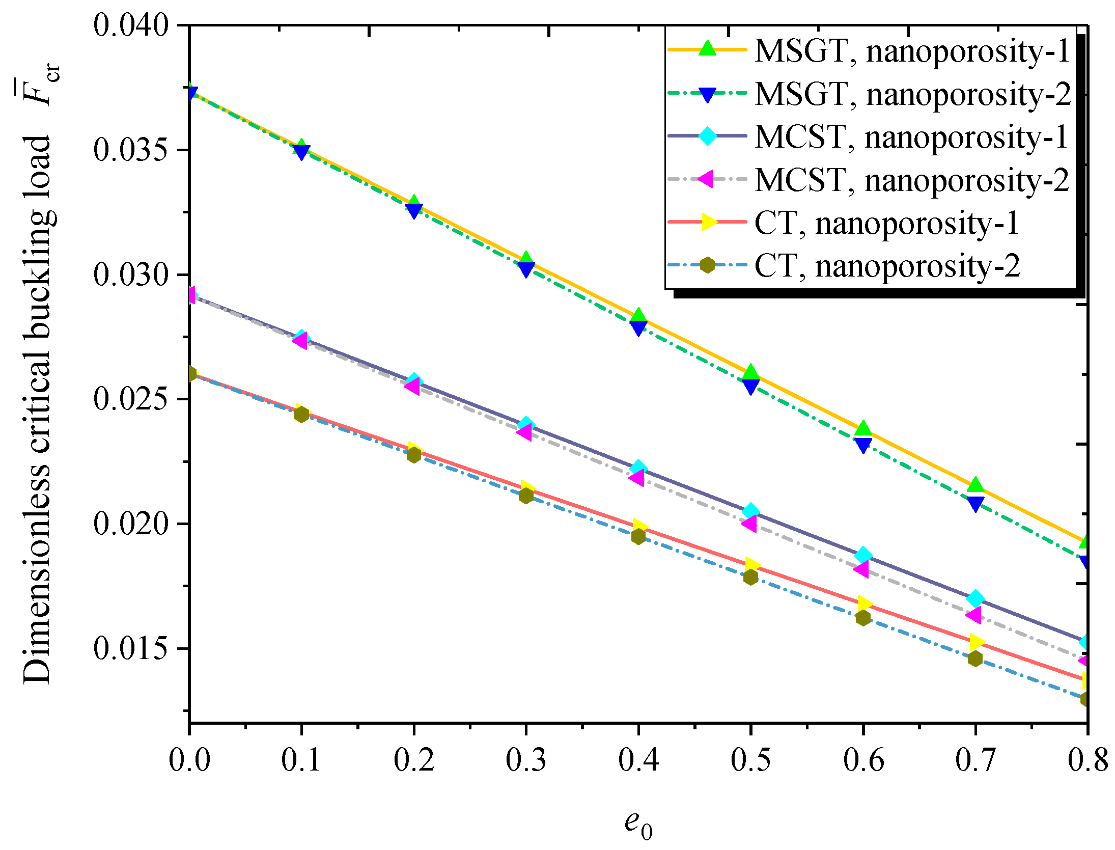
Figure 9.
Dimensionless critical buckling load versus dimensionless length scale parameter (m = 1, n = 2, h = 10 nm, R = 20 h, L = 4R, e0 = 0.5).
Figure 9.
Dimensionless critical buckling load versus dimensionless length scale parameter (m = 1, n = 2, h = 10 nm, R = 20 h, L = 4R, e0 = 0.5).
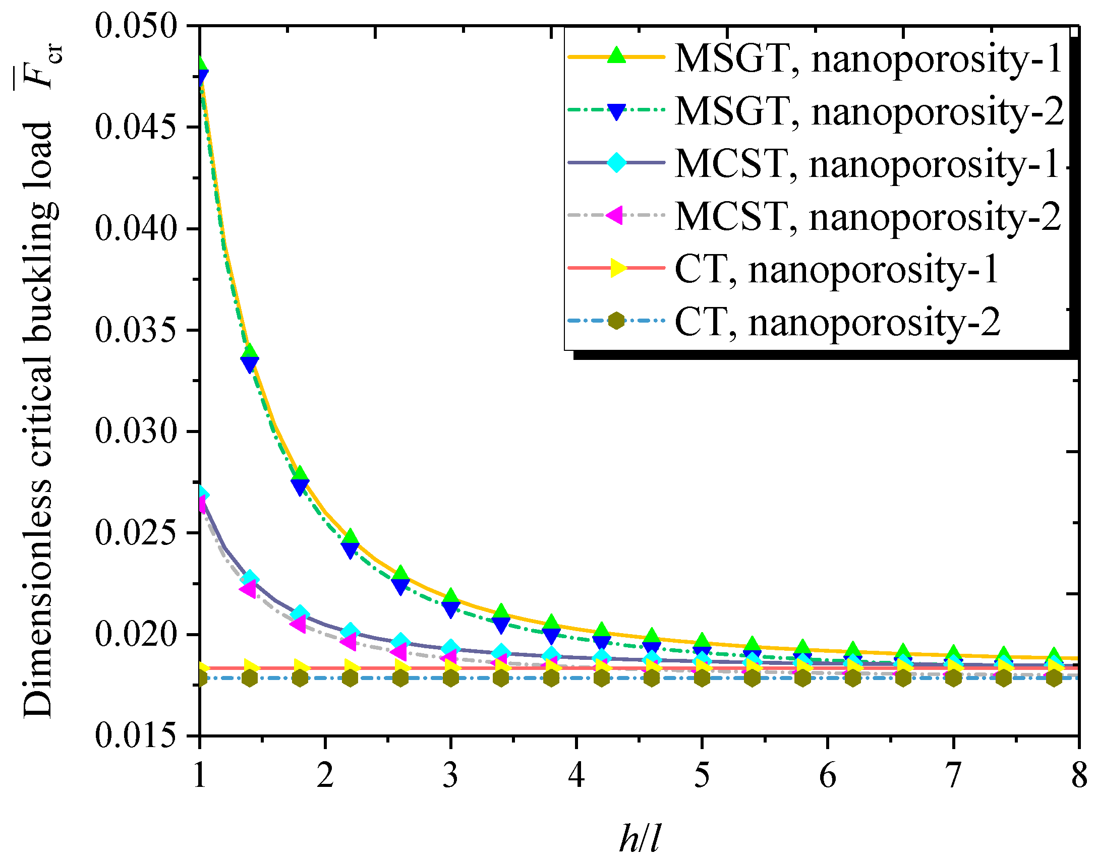
Figure 10.
Dimensionless buckling load versus length-to-radius ratio (m = 1, n = 2, h = 10 nm, R = 20 h, h = 2l, e0 = 0.5).
Figure 10.
Dimensionless buckling load versus length-to-radius ratio (m = 1, n = 2, h = 10 nm, R = 20 h, h = 2l, e0 = 0.5).

Figure 11.
Dimensionless buckling load versus thickness-to-radius ratio (m = 1, n = 2, h = 10 nm, L = 4R, h = 2l, e0 = 0.5).
Figure 11.
Dimensionless buckling load versus thickness-to-radius ratio (m = 1, n = 2, h = 10 nm, L = 4R, h = 2l, e0 = 0.5).

Table 1.
Comparison of dimensionless natural frequency for a homogeneous nanoscale cylindrical shell.
Table 1.
Comparison of dimensionless natural frequency for a homogeneous nanoscale cylindrical shell.
| (m,n) | h/R | l = 0 | l = h | ||||
|---|---|---|---|---|---|---|---|
| Zhang et al. [99] | Present | Error (%) | Zhang et al. [99] | Present | Error (%) | ||
| (1, 1) | 0.02 | 0.19536 | 0.19536 | 0.00 | 0.19595 | 0.19561 | 0.10 |
| 0.05 | 0.19542 | 0.19542 | 0.00 | 0.19908 | 0.19694 | 0.20 | |
| 0.1 | 0.19561 | 0.19564 | 0.01 | 0.20386 | 0.20148 | 1.17 | |
| (2, 2) | 0.02 | 0.25285 | 0.25271 | 0.05 | 0.27108 | 0.27004 | 0.30 |
| 0.05 | 0.25969 | 0.25885 | 0.30 | 0.35606 | 0.34641 | 0.96 | |
| 0.1 | 0.28080 | 0.27931 | 0.50 | 0.50626 | 0.50145 | 0.90 | |
| (3, 3) | 0.02 | 0.27627 | 0.27580 | 0.16 | 0.37783 | 0.37382 | 1.39 |
| 0.05 | 0.31667 | 0.31413 | 0.80 | 0.71543 | 0.69918 | 2.27 | |
| 0.1 | 0.40671 | 0.41916 | 2.97 | 1.08810 | 1.07892 | 0.84 | |
Table 2.
Comparison of dimensionless natural frequency Ω for a homogeneous cylindrical nanoshell (R = 2.32 nm and L/R = 5).
Table 2.
Comparison of dimensionless natural frequency Ω for a homogeneous cylindrical nanoshell (R = 2.32 nm and L/R = 5).
| h/R | (m, n) | l = 0 | l = h | ||||
|---|---|---|---|---|---|---|---|
| Ghadiri et al. [100] | Present | Error (%) | Ghadiri et al. [100] | Present | Error (%) | ||
| 0.02 | m = n = 1 | 0.19536215 | 0.19536215 | 0.00 | 0.19543206 | 0.19548050 | 0.01 |
| m = n = 2 | 0.25271274 | 0.25271274 | 0.00 | 0.25731258 | 0.25785715 | 0.09 | |
| m = n = 3 | 0.27580092 | 0.27580092 | 0.00 | 0.30621690 | 0.30717244 | 0.10 | |
| 0.05 | m = n = 1 | 0.19542305 | 0.19542305 | 0.00 | 0.19585782 | 0.19618570 | 0.16 |
| m = n = 2 | 0.25884786 | 0.25884786 | 0.00 | 0.28543902 | 0.28780026 | 0.80 | |
| m = n = 3 | 0.31407326 | 0.31407326 | 0.00 | 0.45457555 | 0.46000081 | 1.10 | |
Table 3.
Comparison of natural frequencies (Hz) for a simply supported FG cylindrical shell (n = 1, R = 1 m and L/R = 20).
Table 3.
Comparison of natural frequencies (Hz) for a simply supported FG cylindrical shell (n = 1, R = 1 m and L/R = 20).
| h/R | N | Loy et al. [101] | Present | ||||
|---|---|---|---|---|---|---|---|
| m = 1 | m = 2 | m = 3 | m = 1 | m = 2 | m = 3 | ||
| 0.002 | 0 | 13.548 | 4.5920 | 4.2633 | 13.548 | 4.5920 | 4.2633 |
| 0.5 | 13.321 | 4.5168 | 4.1911 | 13.321 | 4.5168 | 4.1911 | |
| 1 | 13.211 | 4.4800 | 4.1569 | 13.211 | 4.4800 | 4.1569 | |
| 2 | 13.103 | 4.4435 | 4.1235 | 13.103 | 4.4434 | 4.1234 | |
| 5 | 12.998 | 4.4068 | 4.0891 | 12.998 | 4.4068 | 4.0891 | |
| 0.05 | 0 | 13.572 | 33.296 | 93.001 | 13.572 | 33.242 | 92.634 |
| 0.5 | 13.345 | 32.702 | 91.319 | 13.345 | 32.645 | 90.943 | |
| 1 | 13.235 | 32.430 | 90.553 | 13.235 | 32.370 | 90.172 | |
| 2 | 13.127 | 32.170 | 89.828 | 13.127 | 32.111 | 89.451 | |
| 5 | 13.021 | 31.910 | 89.109 | 13.021 | 31.854 | 88.743 | |
Table 4.
Effect of length scale parameter on dimensionless natural frequencies Ω based on the MSGT (nanoporosity-1, m = 1, h = 10 nm, R = 20h, L/R = 4, e0 = 0.5).
Table 4.
Effect of length scale parameter on dimensionless natural frequencies Ω based on the MSGT (nanoporosity-1, m = 1, h = 10 nm, R = 20h, L/R = 4, e0 = 0.5).
| h/l = 1 | h/l = 1.5 | h/l = 2 | h/l = 3 | h/l = 4 | h/l = 5 | h/l = 10 | |
|---|---|---|---|---|---|---|---|
| n = 1 | 0.25824 | 0.25723 | 0.25687 | 0.25662 | 0.25653 | 0.25649 | 0.25643 |
| n = 2 | 0.20493 | 0.16730 | 0.15125 | 0.13840 | 0.13356 | 0.13125 | 0.12809 |
| n = 3 | 0.42938 | 0.31512 | 0.25919 | 0.20833 | 0.18683 | 0.17591 | 0.16009 |
| n = 4 | 0.76650 | 0.56684 | 0.46542 | 0.37079 | 0.32994 | 0.30894 | 0.27818 |
| n = 5 | 1.17537 | 0.88269 | 0.72927 | 0.58336 | 0.51961 | 0.48665 | 0.43816 |
| n = 6 | 1.64107 | 1.25206 | 1.04209 | 0.83851 | 0.74844 | 0.70162 | 0.63245 |
Table 5.
Effect of the length scale parameter on dimensionless buckling load based on the MSGT (nanoporosity-1, m = 1, h = 10 nm, R = 20h, L/R = 4, e0 = 0.5).
Table 5.
Effect of the length scale parameter on dimensionless buckling load based on the MSGT (nanoporosity-1, m = 1, h = 10 nm, R = 20h, L/R = 4, e0 = 0.5).
| h/l = 1 | h/l = 1.5 | h/l = 2 | h/l = 3 | h/l = 4 | h/l = 5 | h/l = 10 | |
|---|---|---|---|---|---|---|---|
| n = 1 | 0.12274 | 0.12167 | 0.12129 | 0.12101 | 0.12092 | 0.12087 | 0.12081 |
| n = 2 | 0.04801 | 0.03188 | 0.02603 | 0.02177 | 0.02027 | 0.01957 | 0.01864 |
| n = 3 | 0.18358 | 0.09853 | 0.06657 | 0.04297 | 0.03455 | 0.03062 | 0.02536 |
| n = 4 | 0.55614 | 0.30326 | 0.20422 | 0.12951 | 0.10252 | 0.08987 | 0.07285 |
| n = 5 | 1.27769 | 0.71906 | 0.49043 | 0.31364 | 0.24878 | 0.21820 | 0.17686 |
| n = 6 | 2.45989 | 1.43011 | 0.99029 | 0.64101 | 0.51065 | 0.44875 | 0.36462 |
© 2019 by the authors. Licensee MDPI, Basel, Switzerland. This article is an open access article distributed under the terms and conditions of the Creative Commons Attribution (CC BY) license (http://creativecommons.org/licenses/by/4.0/).
Share and Cite
MDPI and ACS Style
Zhang, Y.; Zhang, F. Vibration and Buckling of Shear Deformable Functionally Graded Nanoporous Metal Foam Nanoshells. Nanomaterials 2019, 9, 271. https://doi.org/10.3390/nano9020271
AMA Style
Zhang Y, Zhang F. Vibration and Buckling of Shear Deformable Functionally Graded Nanoporous Metal Foam Nanoshells. Nanomaterials. 2019; 9(2):271. https://doi.org/10.3390/nano9020271
Chicago/Turabian StyleZhang, Yufei, and Fei Zhang. 2019. "Vibration and Buckling of Shear Deformable Functionally Graded Nanoporous Metal Foam Nanoshells" Nanomaterials 9, no. 2: 271. https://doi.org/10.3390/nano9020271
Note that from the first issue of 2016, this journal uses article numbers instead of page numbers. See further details here.