Article

The Influence of Wire Electrical Discharge Machining Cutting Parameters on the Surface Roughness and Flexural Strength of ZrO2/TiN Ceramic Nanocomposites Obtained by Spark Plasma Sintering

by
Anton Smirnov
1,*,
Anton Seleznev
1,
Nestor Washington Solís Pinargote
1,
Yuri Pristinskiy
1,
Pavel Peretyagin
1 and
José F. Bartolomé
2,*
1
Moscow State University of Technology “STANKIN”, Vadkovsky per. 1, Moscow 127055, Russian
2
Instituto de Ciencia de Materiales de Madrid (ICMM), Consejo Superior de Investigaciones Científicas (CSIC), C/Sor Juana Inés de la Cruz 3, 28049 Madrid, Spain
*
Authors to whom correspondence should be addressed.
Nanomaterials 2019, 9(10), 1391; https://doi.org/10.3390/nano9101391
Submission received: 2 August 2019 / Revised: 17 September 2019 / Accepted: 26 September 2019 / Published: 28 September 2019

Abstract

:
In this work, we characterized the mechanical and electrical properties of zirconia-based ceramic nanocomposites reinforced with 30 and 40 vol. % TiN and fabricated by spark plasma sintering. In addition to their improved mechanical performance, these compositions have sufficient electrical conductivity to allow wire electrical discharge machining (WEDM). The influence of WEDM variables on the roughness and the mechanical strength of samples was analyzed after each cut. The experimental results showed that the roughness of machined surfaces can be reduced by variations in WEDM manufacturing regimes, and, consequently, a drastic drop in flexural strength of workpieces can be avoided. Furthermore, the composites with higher content and homogeneous distribution of the conductive phase exhibited better surface quality as well.

1. Introduction

The toughening effect induced by tetragonal to monoclinic transformation in yttria-stabilized tetragonal zirconia leads to increases in the crack propagation resistance [1]. Moreover, stabilized zirconia offers exceptional resistance to thermal shock as well as physical and chemical wear, making it an ideal material for the production of many difficult applications [2,3,4,5,6,7,8,9,10] where conventional materials often fail.
However, ceramics can contain many microstructural defects of various types, shapes and sizes. These defects are primarily created during fabrication and surface machining, and their presence is unavoidable. Moreover, the machining of ceramic parts is an expensive, difficult and time-consuming process, and diamond tools are often the only tools that can be used for these operations. In this context, electrochemical processes can act as a substitute for the conventional machining of ceramics; these include wire electrical discharge machining (WEDM), which is commonly used (especially for machining hard metals) to avoid expensive grinding and labor-intensive operations for high-quality finish machining operations of workpieces.
However, WEDM only works for electrically conductive materials. In order to be machinable by WEDM, the workpieces should have an electrical resistivity of less than 1–3 Ω·m [11,12,13]. Unfortunately, monolithic zirconia has a high electrical resistivity (>1010 Ω·cm) and, consequently, can only be machined using conventional machining processes.
The electrical conductivity of 3Y-TZP can be increased by the embedding of secondary electrically conductive phases (carbides, nitrides, and borides). In addition, these secondary phases can help to combat the natural brittleness of ceramics and increase their reliability. Moreover, this reinforcement is very important because machining problems can arise during electric discharge due to finish conditions, corrosion of the material and the effect of machining regimes on the surface damage [14,15,16,17,18,19]. This may lead to unintended effects such as cracking in the area between the melted part and the unaffected base material. Therefore, a critical factor in manufacturing ceramic components is to perform cost-effective manufacturing without negatively affecting the mechanical properties. Additionally, it is well known that the mechanical properties of ceramic vary depending on the grain size, which in turn depends on the sintering conditions, namely, temperature and time. For that reason, the spark plasma sintering (SPS) technique can be applied to minimize undesirable grain growth and consequently, the reduction in mechanical properties. Using this solidification technology allows for the rapid fabrication of uniform, fully dense compacts at a lower temperature than conventional sintering techniques, which should help counteract the main drawback of those conventional techniques, that is, the significant grain growth of materials obtained during the process [20,21,22,23,24,25].
The aim of this article is to study the evolution of the mechanical and electrical behavior of ZrO2-based ceramics containing 30 or 40 vol. % TiN. Moreover, the effect of WEDM cutting regimes on the surface quality of the machined samples, which is related to the composites’ bending strength, is evaluated.

2. Materials and Methods

2.1. Nanocomposite Preparation

For this work, commercial tetragonal zirconia (3Y-TZP, d50 = 260 ± 0.05 nm, Tosoh Corp., Tokyo, Japan) and TiN (d50 = 0.9 μm, Plasmotherm, Moscow, Russia, 99.9% purity) powders were used. Powders were wet-mixed for 24 h in a plastic container on a multidirectional mixer Turbula using isopropyl as liquid media. The suspensions were freeze-dried by means of the LabConco FreeZone2.5 freeze dry system (Kansas, MO, USA) at a shelf temperature of +21 ± 2 °C, pressure 0.02 ± 0.01 mBar and condenser temperature of −50 ± 2 °C. This technique is an efficient method to achieve homogeneous particles that are free from agglomerates of TiN inside the ZrO2 matrix as well as avoid a sieving step. Flat discs (50 mm diameter, 5 mm thickness) were produced using a H-HP D-25 SD spark plasma sintering (SPS, FCT Systeme GmbH, Rauenstein, Germany) furnace at 1400 °C under vacuum at 80 MPa axial pressure and 3 min dwell at the final temperature. Two compositions were used: Z30T and Z40T where the numbers show the TiN volume content.

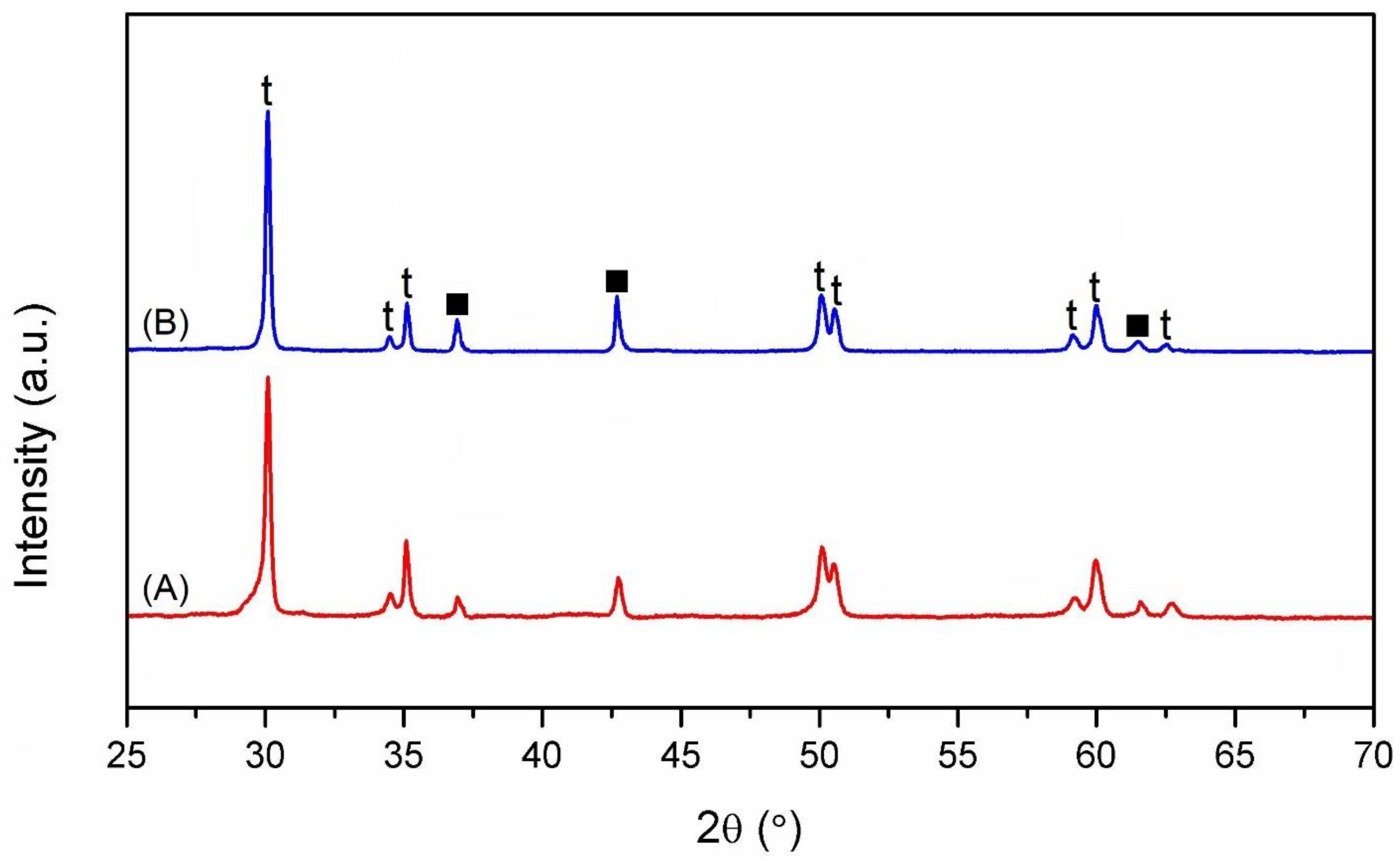
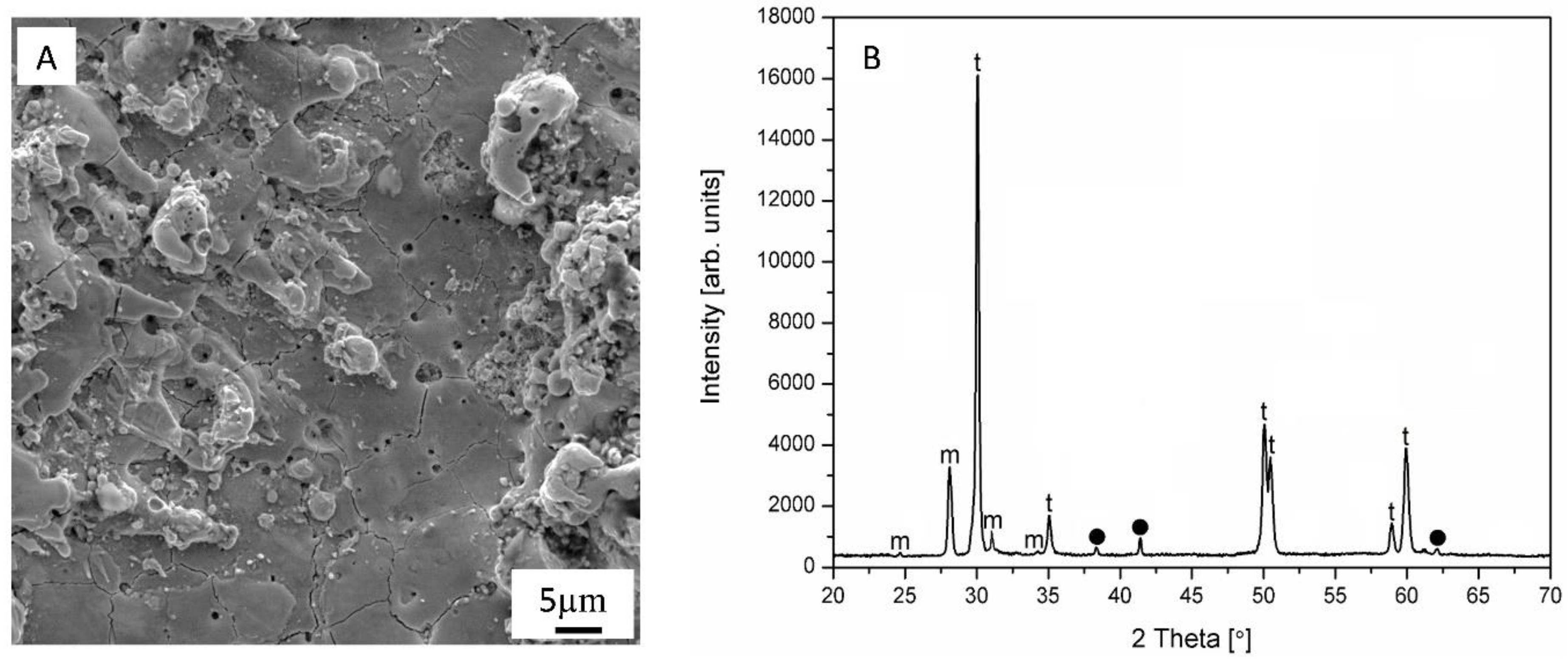
2.2. XRD Characterization

X-ray measurements were carried out using an Empyrean diffractometer (PANalytical, Almelo, Netherlands) with radiation source Cu–Kα (λ = 1.5405981Å) anode supplied with 60 kV and a current of 30 mA.

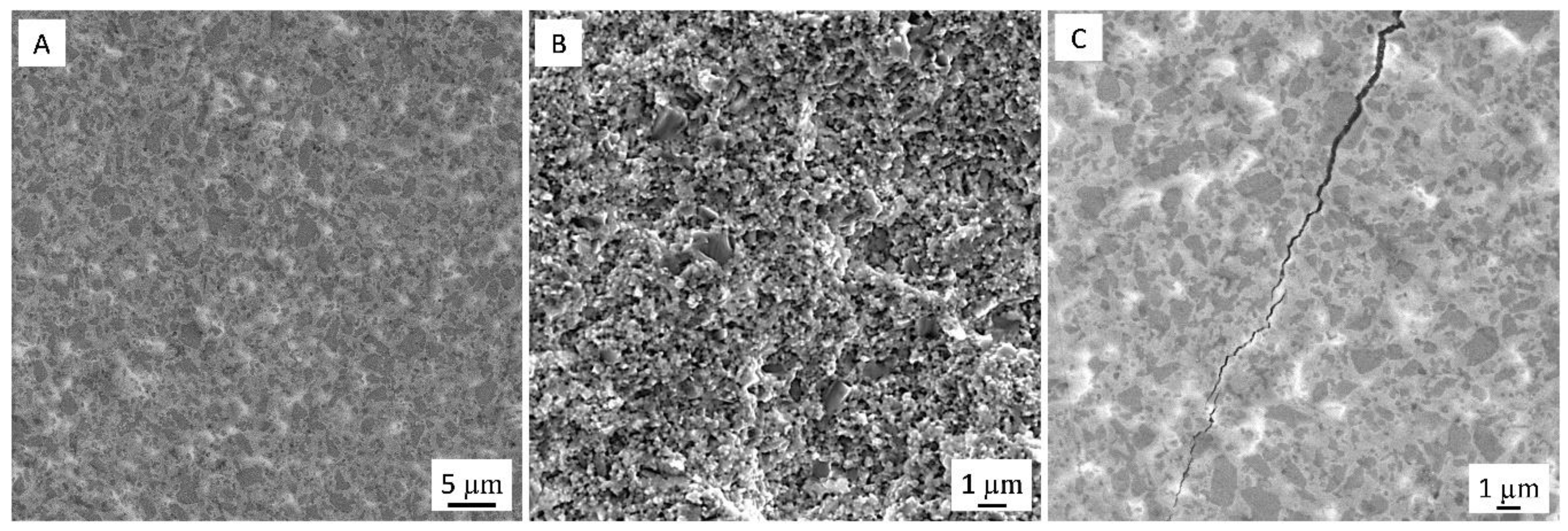
2.3. Microstructural Characterization

Scanning electron microscopy (SEM) characterization of the microstructure of samples polished down to 1 µm and as-machined samples was carried out using a VEGA 3 LMH (Tescan, Brno, Czech Republic) microscope equipped with an energy-dispersive X-ray (EDS) detector. The density (ρ) of the sintered specimens was determined via the Archimedes principle in distilled water. The Vickers hardness (HV) was calculated using the indenter load 9.8 N and 10 indents of each sample. Samples with dimensions of 3.0 × 4.0 × 45 mm3 were used to determine the fracture toughness (KIc) using a single edge notched beam. All tests were realized at ambient temperature using the AutoGraph AG-X (Shimadzu Corp., Kyoto, Japan) universal testing machine of 5 kN capacity with a crosshead speed of 0.5 mm/min and a span of 40 mm. This method and the formulas for calculating KIc have been reported elsewhere [26]. The same machine and specimens with the same dimensions were used for strength (σf) determination using the three-point bending scheme. For this test, as-cut off WEDM bars and traditionally prepared bars were used as bending test specimens. For the traditional preparation method, the sintered disc was firstly cut into prismatic shaped specimens by a diamond wheel and then polished with a 1 µm polycrystalline diamond suspension. The strength was determined according to the equation:
σ f = 3 F L 2 b h 2
where F is the failure load, L is the span, b is the width and h is the height. The strength results were averaged over 10 specimens.

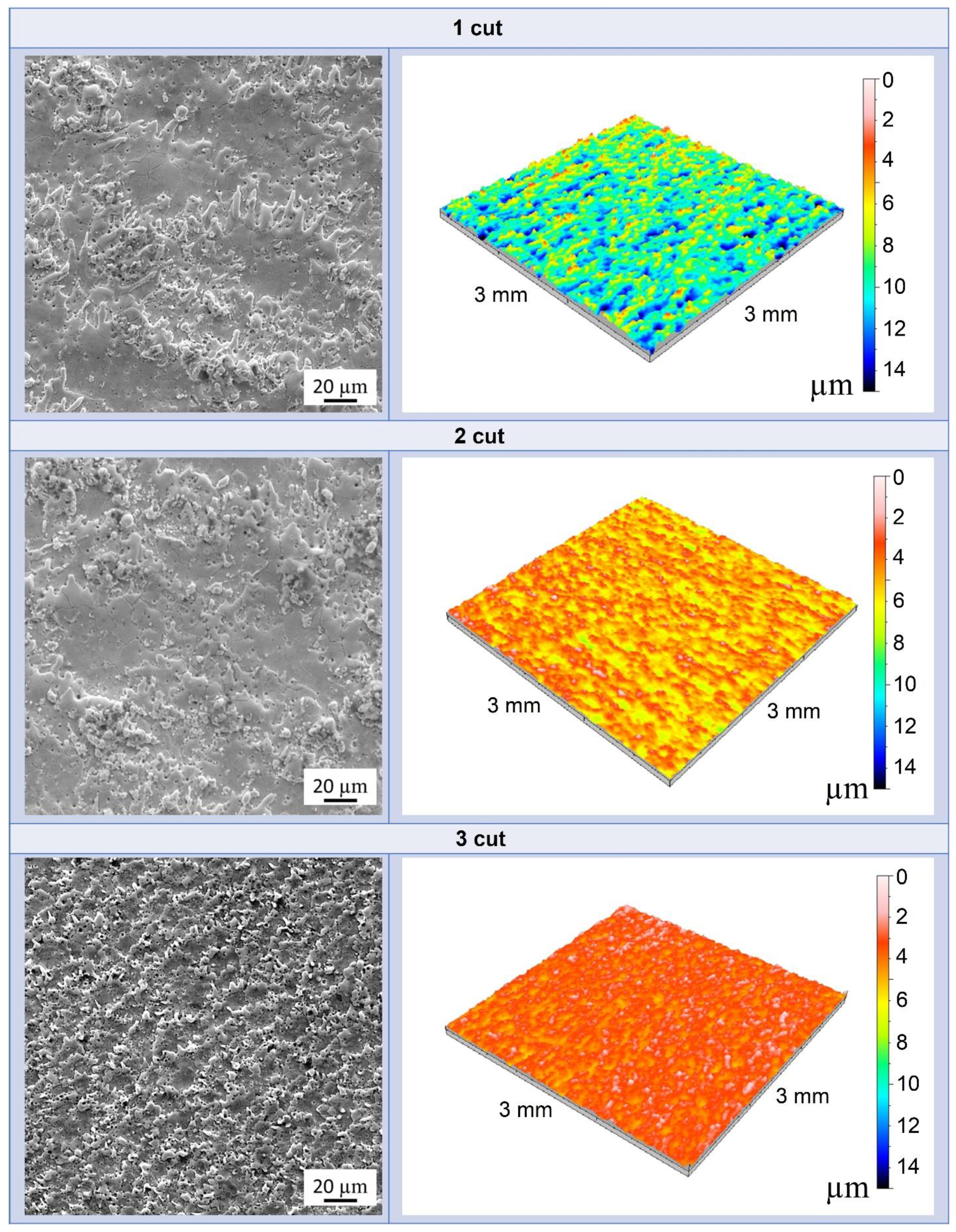
2.4. Determination of Electrical Properties and Wire-Electroerosion Machining (WEDM)

To determine the electrical characteristics of the studied materials, four probe methods with Keithley 6220 current source (Cleveland, OH, USA) and Keithley 2182A nanovoltmeter (Cleveland, OH, USA) were employed.
Specimens were machined by wire EDM (Seibu M500SG, Seibu Electric & Machinery Co., Koga, Japan) machine. Commercial brass wire (Osaka Brasscut A500, 0.25 mm diameter) and deionized water with a conductivity of 0.1 μS/cm were taken as WEDM tools and as a dielectric, respectively. Table 1 shows the three basic machining parameters that were chosen for analysis and optimization, while other settings remained constant. The surface roughness of the processed samples was analysed using a 3D contact profilometer Talysurf CLI 500 (Taylor Hobson, Leicester, UK).

3. Results and Discussion

The X-ray diffractograms of the sintered composites are shown in Figure 1, and reveal the absence of spontaneous martensitic transformation (t → m) of the zirconia particles during cooling.
Additionally, the presence of phases different to zirconia and titanium nitride was not apparent, hence, the possibility of additional compounds or contamination appearing due to processing has been discounted.
SEM images of the polished and fractured surfaces of ceramic composites are presented in Figure 2A,B.
The presence of pores was not observed in the microstructural investigation. Based on the theoretical values of density for ZrO2 and TiN, (6.05 and 5.43 g/cm3, respectively), we found that nearly fully dense (99% th.) composites were fabricated. Moreover, the powder mixing technique was appropriate, as confirmed by the uniform distribution of the second phase in the zirconia matrix.
The mechanical properties and electrical resistivity of the ceramic composites with varying TiN content were compared with the characteristics of monolithic zirconia and summarized in Table 2.
The composites exhibited a higher hardness value than monolithic zirconia, which can be attributed to the higher hardness of TiN (~ 18 GPa). The range of fracture toughness of the composites was 6–6.5 MPa·m1/2. Figure 2C shows the crack propagation on the polished surfaces of ZrO2/TiN composites produced by the Vickers indentation under a load of 9.8 N. The difference between the coefficient of thermal expansion of yttria-stabilized ZrO20–1000 °C = 12 × 10−6/°C) [27] and TiN (α0–1000 °C = 9.4 × 10⁻⁶/°C) [28] will cause compressive residual stresses on the TiN particles (Figure 2C) and tensile stresses on the ZrO2 phase that increase their transformability [26]. Both fracture toughening mechanisms can lead to a higher toughness value in the ZrO2/TiN composites.
The electrical conductivities of the composites were 1.08∙105 and 2.26∙105 S∙m−1 for Z30T and Z40T, respectively, which means the material is suitable for WEDM. This involves interactions between the workpiece and an electrode (gap), which creates thermoelectric energy. The unwanted material is removed from the workpiece through melting and vaporizing, when electric sparks occur between electrodes. Once the sparking cycle occurs, the plasma generates small craters in the neighborhood of the machined front. Additionally, there are regions of fused material caused by wire.
Figure 3 shows the SEM images and three-dimensional color topography of the WEDMed surface of Z40T composites after each cut.
The machined surfaces of both composites show splashes of re-solidified material and pores. The formation of such pores can be explained by the expansion of the nitrogen (N2) and hydrogen (H2) gases from the surface. Because water has been used as a dielectric liquid, it is likely that the formation of these gases occurs due to the oxidation of TiN to TiO2, as illustrated by the following equation:
2 TiN + 4 H 2 O 2 TiO 2 + 4 H 2 + N 2
The SEM image at higher magnification and the corresponding XRD spectrum image of the WEDM surface of Z40T nanocomposite after the third cut are presented in Figure 4A,B, respectively. As can be seen from the SEM image, there are many droplets left on the machined surface due to the high temperature achieved during WEDM, which contributes to material removal. The presence of these droplets suggests that the material removal mechanism is probably melting and evaporation.
Additionally, a network of cracks can be observed on the machined surface. The cracking process could be related to the field of tensile residual stresses, resulting from thermal effects due to the rapid heating and quenching cycles induced during the WEDM process. Furthermore, such cracking probably leads to the tetragonal-to-monoclinic transformation in zirconia and, consequently, to the presence of m-ZrO2 on the machined surface. XRD confirmed that, unlike the polished sintered samples (Figure 1), the WEDM surface layer consists not only of tetragonal and titanium nitride, but also of monoclinic zirconia (Figure 4B).
However, after the third cut a smoother surface and more homogeneous removal of material was observed. Figure 5 exhibits EDS maps of the WEDMed surface of ZrO2-40 vol.% TiN composites after the third cut, showing the homogeneous distribution of the elements throughout the sample.
The presence of Cu and Zn is due to the wire tool material; metal particles move from the electrode to the workpiece during machining and cannot be completely flushed out by the dielectric fluid. EDS was also used for the chemical microanalysis of the polished and machined surface after each cut. The concentration of the elements in the polished versus WEDM finished surface is given in Table 3. It is important to note that, although the EDS measurement error is high in the case of nitrogen and oxygen, the values of these elements on the polished surface are much higher (about 5 times greater) than the values corresponding to the WEDM surface, thus confirming Equation (2).
Table 4 summarizes the results obtained for the surface roughness and bending strength of WEDM specimens as a function of the machining conditions.
The surface roughness is directly related to the critical defect size on the surface of the material, and therefore to the mechanical strength value. The lower the roughness value, the higher the mechanical strength value. It is obvious that the polishing of the samples caused lower surface roughness than the wire electrical discharge machined bars. As would be expected, as a result of using this traditional method of preparation, the ZrO2-TiN materials have the highest bending strength: 1411 and 1423 MPa for Z30T and Z40T, respectively. However, it was revealed that the surface roughness for WEDM cut bars becomes more refined with a higher number of cuts. Therefore, the strength increases as the surface roughness decreases. In addition, the surface quality of the 40 vol. % TiN containing the composite was better after each cut compared to the 30 vol. % TiN composites due to changes in the material removal mechanism and the higher amount of secondary conductive phase.

4. Conclusions

The results obtained revealed that the addition of 30 and 40 vol % TiN phases to the zirconia ceramic matrix improved the mechanical performance and raised the conductivity to a level where wire electrical discharge machining is possible. Moreover, it should be noted that the electrical conductivity and surface quality were simultaneously enhanced in compositions with a higher content of TiN.
It was shown that, after WEDM, the strength is reduced due to the degradation of the surface quality of the machined ceramic nanocomposite. However, applying various cutting conditions allows for increasing the surface quality and, simultaneously, the strength of wire EDM bars to a value very close to that of the polished nanocomposites. These results show the possibility of developing novel conductive ceramic nanocomposites with enhanced mechanical properties that can be obtained by electrical discharge machining for the effective performance of many production activities. Understanding the relationship between cutting parameters, surface topology and their impact on the mechanical performance of a composite will enable the design and processing of zirconia-based ceramic parts with a complex shape.

Author Contributions

Conceptualization, A.S. (Anton Smirnov), J.F.B.; data curation, A.S. (Anton Seleznev), Y.P.; formal analysis, N.W.S.P., P.P.; funding acquisition, P.P.; investigation, P.P., A.S. (Anton Seleznev); methodology, A.S. (Anton Smirnov), J.F.B.; project administration, A.S. (Anton Smirnov), J.F.B.; resources, N.W.S.P., A.S. (Anton Seleznev); software, Y.P., N.W.S.P.; supervision, A.S. (Anton Smirnov), J.F.B.; validation, Y.P., A.S. (Anton Seleznev); visualization, P.P., N.W.S.P.; writing—original draft, A.S. (Anton Smirnov), J.F.B. All authors read and approved the final version of the manuscript.

Funding

We would like to thank the Ministry of Science and High Education of the Russian Federation for supporting this work under contract RFMEFI57718X0288.

Acknowledgments

The contributions of the Metrology Laboratory GIZ MSTU “STANKIN” in the surface roughness measurements are greatly appreciated.

Conflicts of Interest

The authors declare no conflict of interest.

References

  1. Hannink, R.H.J.; Kelly, P.M.; Muddle, B.C. Transformation toughening in zirconia-containing ceramics. J. Am. Ceram. Soc. 2000, 83, 461–487. [Google Scholar] [CrossRef]
  2. Bocanegra-Bernal, M.H.; De La Torre, S.D. Phase transitions in zirconium dioxide and related materials for high performance engineering ceramics. J. Mater. Sci. 2002, 37, 4947–4971. [Google Scholar] [CrossRef]
  3. Solís, N.W.; Peretyagin, P.; Torrecillas, R.; Fernández, A.; Menéndez, J.L.; Mallada, C.; Díaz, L.A.; Moya, J.S. Electrically conductor black zirconia ceramic by SPS using graphene oxide. J. Electroceram. 2017, 38, 119–124. [Google Scholar] [CrossRef]
  4. Kameo, K.; Friedrich, K.; Bartolome, J.F.; Diaz, M.; Lopez-Esteban, S.; Moya, J.S. Sliding wear of ceramics and cermets against steel. J. Eur. Ceram. Soc. 2003, 23, 2867–2877. [Google Scholar] [CrossRef]
  5. Pecharroman, C.; Lopez-Esteban, S.; Bartolome, J.F.; Moya, J.S. Evidence of nearest-neighbor ordering in wet-processed zirconia-nickel composites. J. Am. Ceram. Soc. 2001, 84, 2439–2441. [Google Scholar] [CrossRef]
  6. Sergo, V.; Lughi, V.; Pezzotti, G.; Lucchini, E.; Meriani, S.; Muraki, N.; Katagiri, G.; Nishida, T. The effect of wear on the tetragonal-to-monoclinic transformation and the residual stress distribution in zirconia-toughened alumina cutting tools. Wear 1998, 214, 264–270. [Google Scholar] [CrossRef]
  7. Chen, Z.D.; Myo, M.H.; Choy, C.M. Rapid manufacturing of Y-TZP ceramic punch using powder injection moulding technology. Mater. Sci. Forum 2003, 437, 415–418. [Google Scholar] [CrossRef]
  8. Bartolome, J.F.; Montero, I.; Diaz, M.; Lopez-Esteban, S.; Moya, J.S. Accelerated aging in 3-mol%-yttria-stabilized tetragonal zirconia ceramics sintered in reducing conditions. J. Am. Ceram. Soc. 2004, 12, 2282–2285. [Google Scholar] [CrossRef]
  9. McEntire, B.J.; Bal, B.S.; Rahaman, M.N.; Chevalier, J.; Pezzotti, G. Ceramics and ceramic coatings in orthopaedics. J. Eur. Ceram. Soc. 2015, 35, 4327–4369. [Google Scholar] [CrossRef]
  10. Moya, J.S.; Sanchez-Herencia, J.A.; Bartolome, J.F.; Tanimoto, T. Elastic modulus in rigid Al2O3/ZrO2 ceramic laminates. Scr. Mater. 1997, 37, 1095–1103. [Google Scholar] [CrossRef]
  11. Rodriguez-Suarez, T.; Bartolomé, J.F.; Smirnov, A.; Lopez-Esteban, S.; Díaz, L.A.; Torrecillas, R.; Moya, J.S. Electroconductive Alumina-TiC-Ni nanocomposites obtained by Spark Plasma Sintering. Ceram. Int. 2011, 37, 1631–1636. [Google Scholar] [CrossRef]
  12. Grigoriev, S.; Peretyagin, P.; Smirnov, A.; Solis, W.; Diaz, L.A.; Fernandez, A.; Torrecillas, R. Effect of graphene addition on the mechanical and electrical properties of Al2O3-SiCw ceramics. J. Eur. Ceram. Soc. 2017, 37, 2473–2479. [Google Scholar] [CrossRef]
  13. Grigoriev, S.; Volosova, M.; Peretyagin, P.; Seleznev, A.; Okunkova, A.; Smirnov, A. The Effect of TiC additive on mechanical and electrical properties of Al2O3 ceramic. Appl. Sci. 2018, 8, 2385. [Google Scholar] [CrossRef]
  14. Puertas, I.; Luis, C.J.; Álvarez, L. Analysis of the influence of EDM parameters on surface quality, MRR and EW of WC–Co. J. Mater. Process. Technol. 2004, 154, 1026–1032. [Google Scholar] [CrossRef]
  15. Khan, A.A.; Ali, M.; Shaffiar, M. Relationship of surface roughness with current and voltage during wire EDM. J. Appl. Sci. 2006, 6, 2317–2320. [Google Scholar]
  16. Díaz, L.A.; Solís, N.W.; Peretyagin, P.; Fernández, A.; Morales, M.; Pecharromán, C.; Moya, J.S.; Torrecillas, R. Spark plasma sintered Si3N4/TiN nanocomposites obtained by a colloidal processing route. J. Nanomater. 2016, 2016, 68. [Google Scholar] [CrossRef]
  17. Obara, H.; Satou, H.; Hatano, M. Fundamental study on corrosion of cemented carbide during wire EDM. J. Mater. Process. Technol. 2004, 149, 370–375. [Google Scholar] [CrossRef]
  18. Smirnov, A.; Peretyagin, P.; Bartolome, J.F. Wire electrical discharge machining of 3Y-TZP/Ta ceramic-metal composites. J. Alloys Compd. 2018, 739, 62–68. [Google Scholar] [CrossRef]
  19. Smirnov, A.; Peretyagin, P.; Bartolome, J.F. Processing and mechanical properties of new hierarchical metal-graphene flakes reinforced ceramic matrix composites. J. Eur. Ceram. Soc. 2019, 39, 3491–3497. [Google Scholar] [CrossRef]
  20. Rice, R.W. Effects of environment and temperature on ceramic tensile strength–grain size relations. J. Mater. Sci. 1997, 32, 3071–3087. [Google Scholar] [CrossRef]
  21. Eichler, J.; Rödel, J.; Eisele, U.; Hoffman, M. Effect of grain size on mechanical properties of submicrometer 3Y-TZP: Fracture strength and hydrothermal degradation. J. Am. Ceram. Soc. 2007, 90, 2830–2836. [Google Scholar] [CrossRef]
  22. Smirnov, A.; Kurland, H.-D.; Grabow, J.; Müller, F.A.; Bartolomé, J.F. Microstructure, mechanical properties and low temperature degradation resistance of 2Y-TZP ceramic materials derived from nanopowders prepared by laser vaporization. J. Eur. Ceram. Soc. 2015, 35, 2685–2691. [Google Scholar] [CrossRef]
  23. Viswanathan, V.; Laha, T.; Balani, K.; Agarwal, A.; Seal, S. Challenges and advances in nanocomposite processing techniques. Mater. Sci. Eng. Rep. 2006, 54, 121–185. [Google Scholar] [CrossRef]
  24. Smirnov, A.; Beltrán, J.I.; Rodriguez-Suarez, T.; Pecharromán, C.; Muñoz, M.C.; Moya, J.S.; Bartolomé, J.F. Unprecedented simultaneous enhancement in flaw tolerance and fatigue resistance of zirconia–Ta composites. Sci. Rep. 2017, 7, 44922. [Google Scholar] [CrossRef] [PubMed]
  25. Smirnov, A.; Peretyagin, P.; Solís Pinargote, N.W.; Gershman, I.; Bartolomé, J.F. Wear behavior of graphene-reinforced alumina–silicon carbide whisker nanocomposite. Nanomaterials 2019, 9, 151. [Google Scholar] [CrossRef] [PubMed]
  26. Smirnov, A.; Bartolomé, J.F.; Kurland, H.-D.; Grabow, J.; Müller, F.A. Design of a new zirconia-alumina-Ta micro-nanocomposite with unique mechanical properties. J. Am. Ceram. Soc. 2016, 99, 3205–3209. [Google Scholar] [CrossRef]
  27. Morrell, R. Handbook of Properties of Technical & Engineering Ceramics, an Introduction for Engineer and Designer, Part 1; Her Majesty’s Stationery Office (HMSO): London, UK, 1985; pp. 95–166. [Google Scholar]
  28. Pierson, H.O. Handbook of Refractory Carbides and Nitrides: Properties, Characteristics, Processing and Applications; William Andrew: Norwich, NY, USA, 1996; pp. 183–187. [Google Scholar]
Figure 1. XRD patterns of polished surfaces of ZrO2-TiN composites with 30 (A) and 40 (B) vol. % TiN content (labelling “t” and “■” denote tetragonal zirconia and TiN, respectively).
Nanomaterials 09 01391 g001
Figure 2. SEM micrographs of polished (A) and fractured (B) surface of zirconia-based composites with 40 vol. % TiC. (C) Vickers indentation crack induced on the surface of the Z40T composites. Dark phase on the micrographs is the TiN phase.
Nanomaterials 09 01391 g002
Figure 3. SEM images and 3D topographies corresponding to Z40T composites WEDMed surface with a depth scale (colored scale) as a function after each cut.
Nanomaterials 09 01391 g003
Figure 4. Topography (A) and corresponding XRD pattern (B) of the WEDMed surface of Z40T nanocomposite. The labels, “t” and “m” denote tetragonal and monoclinic zirconia, respectively. “●” marks TiN reflections.
Nanomaterials 09 01391 g004
Figure 5. The WEDMed surface of Z40T composite and X-ray element distribution maps.
Nanomaterials 09 01391 g005
Table 1. Wire electrical discharge machining parameters.
Machining Conditions
Average Working Voltage (V)Average Working Current (A)Off Time (μs)
1 cut1003.08
2 cut842.24
3 cut721.52
Table 2. Mechanical properties and electrical conductivity of ZrO2-TiN composites.
Specimen Density [%ρth] Elastic Modulus E [GPa]Hardness HV [GPa]Fracture Toughness KIc [MPa∙m1/2]Electrical Conductivity × 105 [S∙m−1]
3Y-TZP [22]99198 ± 513 ± 0.36.1 ± 0.3-
Z30T99237 ± 713.9 ± 0.46.3 ± 0.21.08
Z40T99252 ± 813.8 ± 0.36.5 ± 0.32.26
Percent theoretical density.
Table 3. Elemental analysis of polished surface vs. WEDM surface of Z40T composite.
ElementPolished SurfaceWEDM Surface
Cut 1Cut 2Cut 3
Wt.%Atm.%Wt.%Atm.%Wt.%Atm.%Wt.%Atm.%
N16.3520.472.575.102.9505.262.784.95
O27.2444.2127.1444.4727.8445.69827.4345.42
Ti17.1611.8617.6212.1017.4811.9817.5312.06
Y1.210.492.030.622.140.822.090.78
Zr38.0422.9738.5823.7238.1723.4738.3623.58
Cun.a.n.a.4.243.623.893.244.153.34
Znn.a.n.a.1.651.152.081.442.021.09
Aln.a.n.a.0.280.310.230.290.260.35
Cn.a.n.a.5.898.915.227.525.388.43
Table 4. The WEDM cutting parameters influence on surface roughness and strength values.
Z30TZ40T
Machining Conditions
Traditional Preparation1 Cut2 Cut3 CutTraditional Preparation1 Cut2 Cut3 Cut
Surface roughness, Sa (μm)0.21 ± 0.023.08 ± 0.082.11 ± 0.051.1 ± 0.030.22 ± 0.022.84 ± 0.051.73 ± 0.03 0.89 ± 0.02
Flexural strength, σf (MPa)1411 ± 321226 ± 1021287 ± 611319 ± 371423 ± 291267 ± 871323 ± 431373 ± 31

