Optical Boundaries for LED-Based Indoor Positioning System


1
School of Engineering and Built Environment, Glasgow Caledonian University, Glasgow G4 0BA, UK
2
Institute for Digital Communications, University of Edinburgh, Edinburgh EH9 3JL, UK
*
Author to whom correspondence should be addressed.
Computation 2019, 7(1), 7; https://doi.org/10.3390/computation7010007
Submission received: 17 December 2018
/
Revised: 5 January 2019
/
Accepted: 9 January 2019
/
Published: 14 January 2019
(This article belongs to the Special Issue Optical Wireless Communication Systems)
Abstract
:Overlap of footprints of light emitting diodes (LEDs) increases the positioning accuracy of wearable LED indoor positioning systems (IPS) but such an approach assumes that the footprint boundaries are defined. In this work, we develop a mathematical model for defining the footprint boundaries of an LED in terms of a threshold angle instead of the conventional half or full angle. To show the effect of the threshold angle, we compare how overlaps and receiver tilts affect the performance of an LED-based IPS when the optical boundary is defined at the threshold angle and at the full angle. Using experimental measurements, simulations, and theoretical analysis, the effect of the defined threshold angle is estimated. The results show that the positional time when using the newly defined threshold angle is 12 times shorter than the time when the full angle is used. When the effect of tilt is considered, the threshold angle time is 22 times shorter than the full angle positioning time. Regarding accuracy, it is shown in this work that a positioning error as low as 230 mm can be obtained. Consequently, while the IPS gives a very low positioning error, a defined threshold angle reduces delays in an overlap-based LED IPS.
1. Introduction
Indoor positioning forms an integral part in the development of future technologies and its importance in daily activities cannot be overemphasized. Application areas for indoor positioning systems range from smart monitoring of people and facilities in an indoor location to enhanced search and rescue operations during emergencies [1,2]. As a result, indoor positioning has been the subject of increasing research interest over the past decade. The central idea behind the design of an indoor positioning system is to establish a ‘transmitter-receiver communication’ link and use a signal parameter to determine the location of the receiver [3]. Using radio frequency (RF) communication channels, ZigBee, Bluetooth, ultra-wideband, and WiFi have all been used to develop indoor positioning systems [4]. However, the possibility of multipath reflections and interference with other RF-based devices makes RF unsuitable for indoor positioning [5]. The use of magnetic or induction-based systems and ultrasound systems has been investigated for indoor positioning, but these systems come with high installation costs [6,7]. In addition, magnetic systems can interfere with other sensitive electromagnetic signals (such as those in hospitals).
Light emitting diodes (LEDs) have been receiving attention recently in the context of positioning due to their cost, lighting characteristics, and ability to communicate. LED-based positioning has been extensively investigated with major techniques such as received signal strength (RSS) [8], proximity [9], fingerprinting [10], arrival techniques (which include angle of arrival (AoA) [11], time of arrival (ToA), time difference of arrival (TDoA), phase difference of arrival (PDoA), and image-based positioning [3]. The proximity technique has the simplest positioning algorithm and is the most inexpensive to implement, however the accuracy of such systems is usually low [12]. RSS, AoA, fingerprinting, and image based techniques are also popular forms of LED-based indoor positioning with a very high accuracy [13,14]. Despite the high accuracy these techniques promise, LED-based indoor positioning and indoor positioning in general has been reported as a problem yet to be solved [5]. This is because these highly accurate positioning techniques have been approached with a view to increasing accuracy alone. However, in real life situations, the complexity of the receiver (or mobile unit), the size (weight and volume) of the deployed hardware, the wearability of the receiver, and the positioning time are equally important factors. Ignoring these factors leads to systems that have complex algorithms which are computationally intensive and very expensive to implement [5]. When implemented, the receiver requires hardware of a large size which requires high amounts of electrical power for their operation. Previous works on LED-based positioning which implement their algorithms are presented in Table 1. By the use of heavy and large receiver systems, it can be observed that the wearability of the receiver system has not been properly considered in various indoor positioning system (IPS) design techniques.
From Table 1, the simplest algorithm is the proximity method but this technique has the highest amount of errors. Methods to improve the accuracy of this system have been investigated but all solutions make the system much more complex. An advanced overlap-based proximity technique called the multiple LED estimation model (MLEM) is chosen as a motivation for further research in an attempt to improve the performance of proximity based IPS while keeping the complexity and cost of the system low [66].
Although smart phones have been used as mobile receivers, holding a phone round the clock for the sole purpose of positioning might not be convenient. To the best of the author’s knowledge, wearable receivers for indoor positioning were first demonstrated in Reference [66]. The system uses the proximity technique of LED-based positioning due to its simple algorithm. However, since the optical power from LEDs follows a Lambertian distribution, the performance of the IPS is observed to change when the receiver moves towards the edges of the LED beam, which are called the optical boundaries. As a mobile receiver moves from the region of one LED to another, it crosses optical boundaries where the optical power is drastically reduced (almost to zero).
There has not been much emphasis on optical boundaries affecting optical wireless communication (OWC) because the focus has been placed on meeting high data-rate demands [67,68,69]. Conditions that provide sufficient optical power for OWC have been used for investigations to achieve higher data rates. In situations where the receiver is subject to harsh channel models, optical link budget analysis or advanced optical modulation techniques are used to design the optical system. Short distance investigations in Reference [70,71,72] with stationary receivers have been used for indoor measurements, while for outdoor investigations, lasers or collimating lenses have been used [73,74]. Although collimated light beams have their advantages in long distance optical signal propagation, the dispersed light beams from off-the-shelf LEDs are a better choice for the low data rates needed in indoor positioning systems. On a horizontal plane, the region covered by the dispersed beam from an LED, called the optical footprint, does not have a well-defined boundary. Information on the LED footprint has always been communicated in terms of the angle at half power from various manufacturer datasheets. However, as is shown in this work, this information suffices for the use of such LEDs in optical wireless communication, but not in optical proximity-based positioning. This is because, in optical proximity positioning, the LED footprint is very important in determining the accuracy of the positioning. In addition, a moving person may bend toward or away from the LED transmitter. This bending that turns the receiver away from the transmitter is known as receiver tilt.
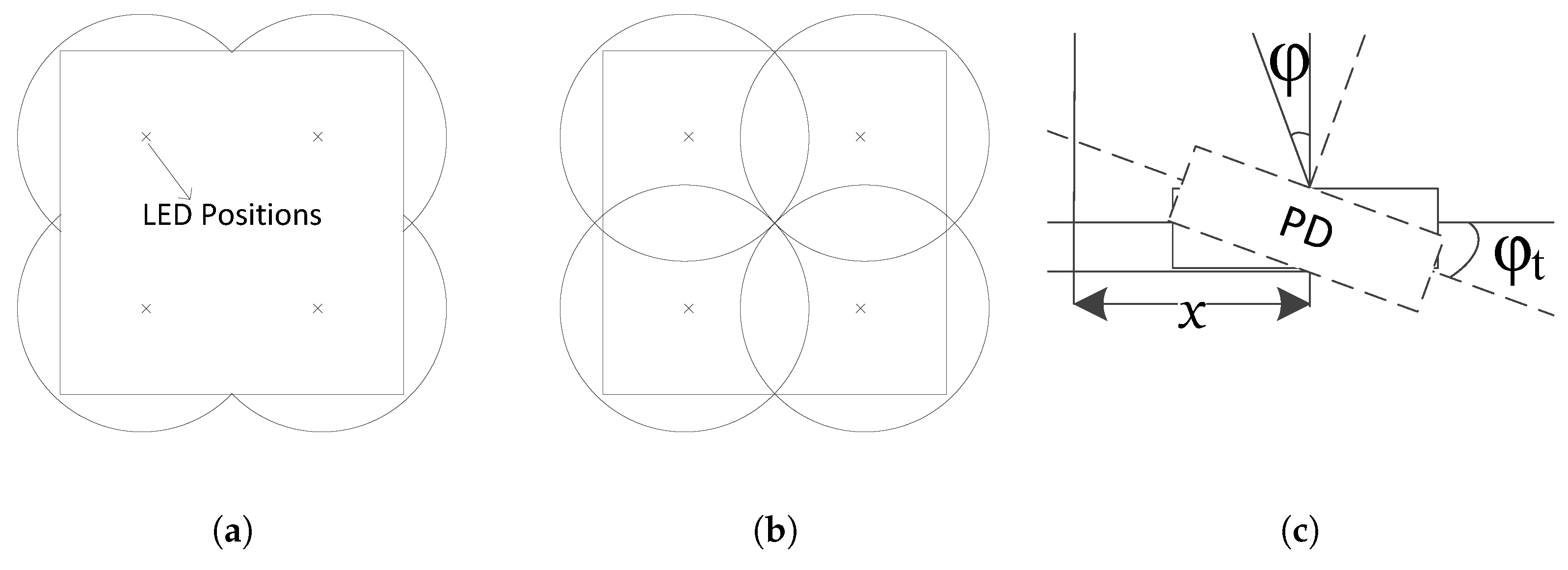
Optical proximity-based IPS determines the location of an object based on the signal information received [16]. A mobile receiver can only receive this information if the receiver is within the LED footprint. The accuracy of positioning is dependent on the size of the footprint of the LED. Proximity-based indoor positioning systems have been shown to improve accuracy with the use of overlapping LED beams in a MLEM while keeping the receiver wearable [19,75]. By uniquely programming each LED, more identifiable regions are created as illustrated in Figure 1a,b. Figure 1a shows the conventional proximity LED IPS which only identifies a room [16,76]. Figure 1b shows the use of MLEM, with seven additional identifiable regions which are used to increase the positioning accuracy [77]. However, this model has the possibility of LED data packet collisions in the overlap regions. By using packet duration multiplexing (PDM), the collision can be reduced [75,78]. However, Ref. [12,16] this assumes that an LED beam with a definite cut-off angle is used to define overlap conditions for an increase in positioning accuracy.In practice, this is not so. Moreover, when the receiver is tilted as illustrated in Figure 1c, the optical boundaries change.
This paper investigates the performance of transmitted optical signals at the optical boundaries and its effect on LED-based positioning. This effect is quantified by measuring the positioning time, which is the time required to know a position. The effect of considering optical boundaries on positioning accuracy is also examined. Investigations of the effect of encoding design and receiver tilts on positioning near the optical boundaries are also carried out and suggestions are given for LED positioning protocol designs based on the results of these investigations.
The rest of the paper is organized as follows: in Section 2, the system model showing the problem is described. The derivation of the threshold angle for defining optical boundaries is presented in Section 3. Investigation of the effects of encoding protocol design, and the effects of overlap and receiver tilt in the optical boundaries on positioning are explained in Section 4. The results and discussion are given in Section 5. Finally, in Section 6, the conclusions are presented.
2. System Model
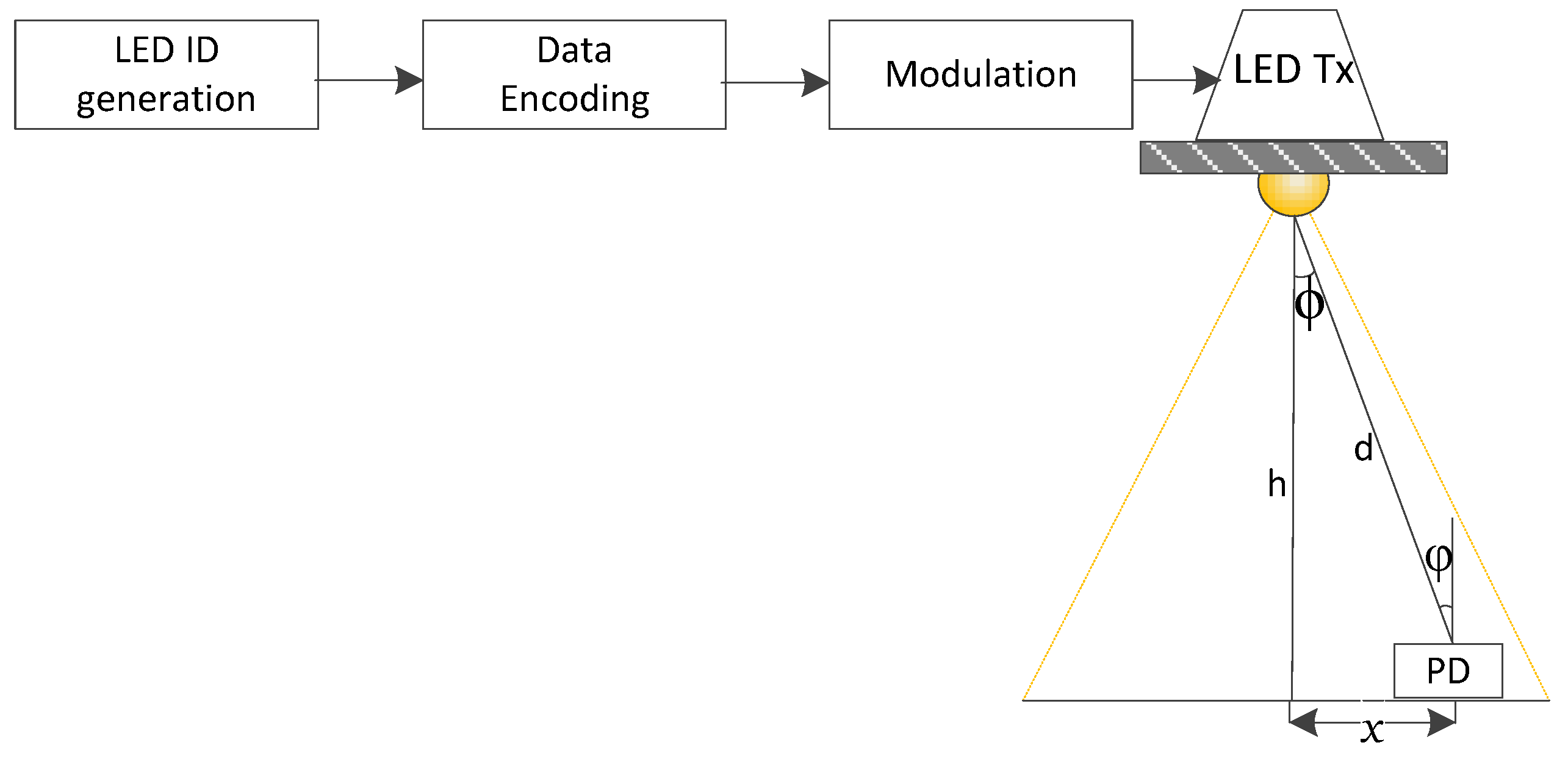
The system model for investigating the optical boundaries is developed based on the transmitter front end as shown in Figure 2.
Considering a typical room size of dimensions 5 m × 5 m × 3.5 m, where the receiver is on a horizontal plane at a distance of h m from the transmitter. The power received at a location in the room is given by , where is the optical power transmitted from the LED, and is the DC channel gain for directed line of sight (LOS) given in Reference [34,79,80] as
where A is the physical area of the PD, d is the LOS distance between the transmitter and the receiver, is the angle of irradiance with respect to the transmitter’s perpendicular axis, and is the angle of incidence with respect to the receiver axis. is the transmission of the optical filter and is assumed to be in unity for this work as this assumption does not affect generality [81], is the field of view of the receiver, is the gain of the optical concentrator given as a function of the refractive index n as
m is the order of the Lambertian source and is
where is the half angle of the LED transmitter.
In this work, the received optical power as the mobile receiver moves along the horizontal plane is expressed in terms of the angle of irradiance at the receiver with respect to the transmitter’s perpendicular axis. On the basis of Figure 2, the horizontal displacement x can be evaluated from this figure as .
Problem Description
In this section, the problems with indoor positioning at the boundaries of the LED footprints are identified. Given that the distance between the transmitter and receiver plane h is 3 m, the plots of the normalized received optical power of two LEDs (OSRAM SFH 4554 and VISHAY TSFF 5510 called LED and LED) with the properties given in Table 2 are shown in Figure 3. The normalized received optical power is the ratio of the received optical power to the peak received optical power. Taking the region beyond which the optical power is not detectable as the optical boundary. Peak optical power is received at the angle of incidence point for both LEDs. The received optical power starts to reduce, as the mobile receiver moves towards the half angle. At the half angle, the optical power is still sufficiently high to give accurate positioning. Therefore, this angle is not suitable in defining the optical boundary for indoor positioning. At the full angle, which is twice the half angle ( for LED and for LED), the normalized optical power for LED is , while that for LED is almost 0. These inconsistencies around the half- or full-angle-based boundaries of the LED cause a mobile receiver to perform inconsistently when it is in the boundary region. In addition, wearable mobile receivers are subject to tilting. The received optical power as the PD moves along the horizontal plane is presented in Figure 4 for when the PD in Figure 2 is tilted at , , , and to the right of LED. The boundary for positioning is seen to vary with the angle of tilt for a receiver. Consequently, neither the half angle nor full angle is enough to determine the boundary of proximity-based IPS. In view of this, a threshold angle, based on the receiver design, which suffices in determining the boundaries for positioning is defined in this work.
3. Optical Boundary Definition
In this section, the optical boundary of the system in Section 2 is defined in terms of the positioning system parameters. The optical boundary depends on two major sets of design parameters. First are the physical system parameters, which are derived from the transmitter properties, receiver properties, and receiver orientation. These parameters are given in Table 2 and their effects are quantified using the channel model (1). The second sets of parameters are the communication system parameters which are determined by the positioning communication protocol design. The effect of the encoding scheme design on the optical boundaries is estimated in Section 4.1.
3.1. Noise Determination for the System Model
To determine the effect of the aforementioned design parameters on positioning for the system model considered, the bit error rate (BER) is required. The BER is derived from the relationship between the BER and signal to noise ratio (SNR). The SNR is given in Reference [82] by
where is the responsivity of the photodetector, and is the total noise in the receiver system which is given as
where and are the shot noise and thermal noise, respectively, as described in Reference [82]. On-off keying (OOK) modulation is used to determine the total noise value in this system experimentally by computing the Q-factor given in Reference [83] by
where and are the on and off voltage levels and and are the noise deviation at the on and off voltage levels of the OOK modulated pulse. Laboratory measurements of , , , and are taken at height h to compute Q. From the value of Q, the BER is calculated by
3.2. Threshold Angle for Optical Boundary
The boundary of LED footprints varies for different optical transmitter and receiver orientations as illustrated in Figure 4. In order to establish a common ground for designs, a threshold angle is defined as the angle where a minimum number of transmitted packets are received. Therefore, the threshold angle occurs when the packet delivery ratio (PDR), which is the ratio of the number of packets received to the number of packets transmitted, is greater than or equal to a specified value . Given there are independent bits in a packet and that for successful packet reception all of these bits must be received without error, the PDR is defined in terms of BER as
therefore the required BER to yield is given by
On the basis of the relationship between the BER, SNR, and defined in (4) and (1), the threshold angle is given as
Therefore, given number of bits in a designed positioning protocol and the minimum required PDR , the threshold angle can be evaluated.
4. Investigations Showing the Effect of Defined Optical Boundaries
Three investigations which are carried out to show the effects of receiver-based optical boundaries are explained in this section. First is the effect of positioning protocol design for a single LED transmitter, next is the effect of overlap for multiple LED transmitters in an overlap region, and then, the effect of tilt in the overlap region. Finally, the effect of all these on positioning accuracy is quantified.
4.1. Boundary Based Positioning Protocol
The three major modules which describe the transmitter are LED ID generation, data encoding, and modulation as shown in Figure 2. For investigation purposes in this section, the LED ID is generated using normal random variables with equal probability of ones and zeros. The generated binary data is encoded and then modulated to a 38 kHz frequency. The optical energy content in the signal is dependent on the encoding protocol and type of modulation scheme used. Encoding not only marks start and stop bits for frame synchronization, it also maps ones and zeros to pulses of different high and low duration depending on the scheme used. In the design of an encoding protocol for a frame, pulses of duration L are used to encode the data such that a one in bi-phase coding (BPC) as explained in Reference [85] is a high pulse of duration L followed by the zero of duration L, and a zero is encoded as a low pulse of duration L followed by a high pulse of duration L. With pulse width modulation (PWM) based encoding, three different relationships can be established between the representation of ones and the representation of zeros. They can be additive, where the widths of pulses are designed to be in linear increments of L. For instance, one is represented by L and zero by . Pulses can also be designed to operate in gains, where the widths of pulses are designed to be in multiplicative increments. Finally, pulses can be represented in exponents where the widths are in the form L and . If and are two orthonormal basis functions, a signal space representation for each of the above-mentioned schemes can be written as represented in Table 3.
To show the effects of pulse duration on BER and PDR, the BPC in Table 3 is used to form packets for the transmission of positional information. The packets are transmitted considering the Lambertian channel model for LEDs as described in (1), where the transmitted power is based on the energy signal. Noise from Section 3.1 is used to calculate the SNR, and the BER is calculated using (9). The effect of the encoded pulse duration L on the BER and delay in positioning is estimated in Section 5.4.
4.2. Quantifying Effect of Full Angle Positioning Boundary
In this section, the process of examining the effect of the conventional full angle positioning boundary on an IPS with single and overlapping LED beams is explained. In the full angle positioning boundary, a receiver in the boundary region takes a longer time to determine its position due to the low SNR in the region. This is because low SNR causes a higher BER which leads to reduced PDR. Since packets with error are discarded, the receiver waits for a longer time to receiver errorless packets. This wait increases positioning time. Consequently, analysis to show the effect of the full angle boundary on positioning is done by determining the average positioning time (APT) when the full angle is used as the LED beam region and repeating the process using the threshold angle.
Considering an untilted receiver at an incidence angle from the transmitter, if the BER at this point is BER for a single LED transmitting bits in a packet, given the pulse duration L and the PDR from (11) PDR, the positioning time is computed as
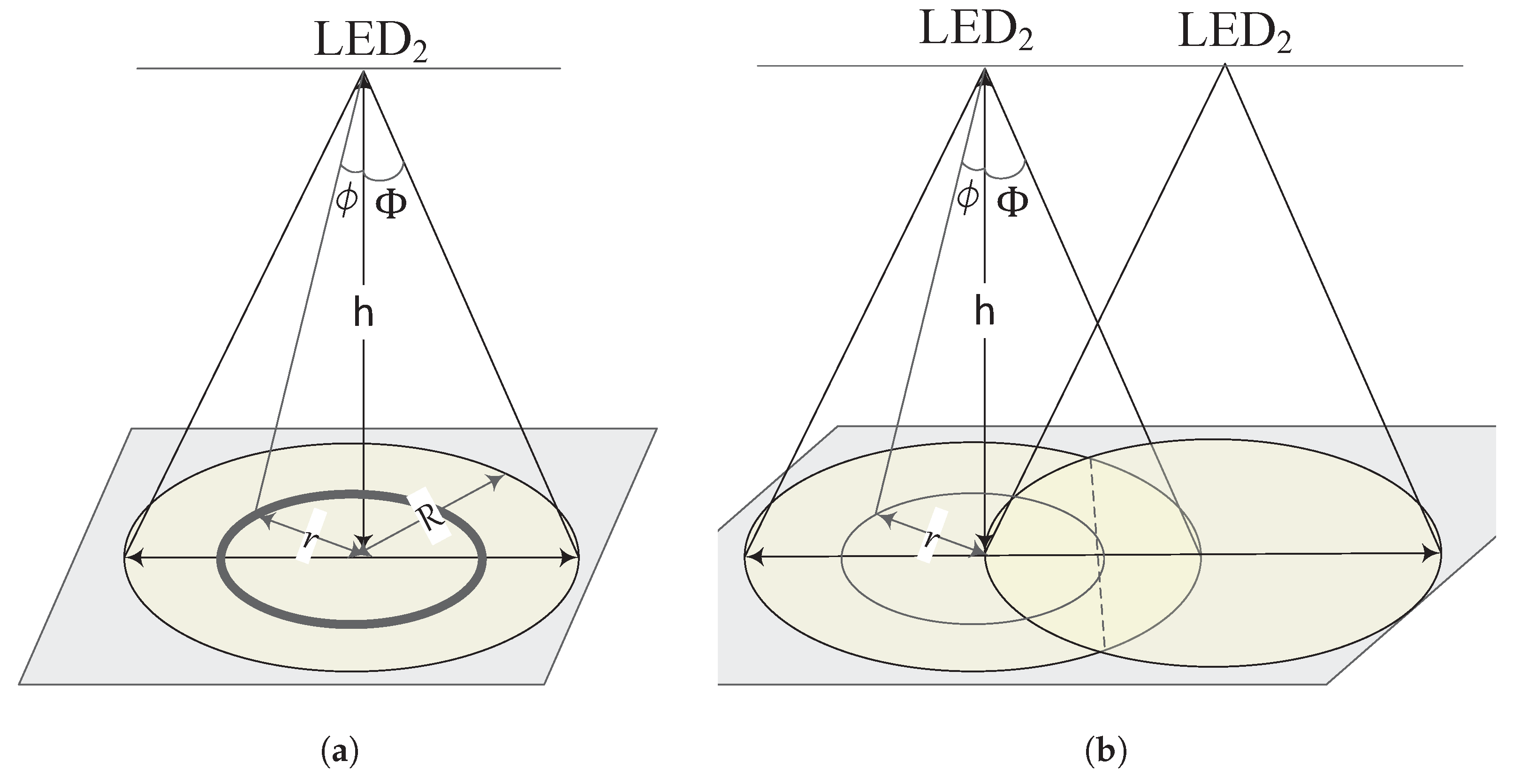
For a single LED positioning system illustrated in Figure 5a with the radius of beam being R at the full angle of LED, if the positioning time at a point with incidence angle is , the positioning time of all points on a circle at the radius r is given as . By geometry, . Therefore, the positioning time for all points in the LED beam is given as
The APT is the ratio of the total positioning time to the total number of points given by the area of the beam. Therefore the APT is
Given that , can be written as
For the system with two overlapping LED beams, a probabilistic PDM process is introduced in Reference [66,75] to handle collisions. In the region where two LED beams meet, the positioning time is taken as the time to receive packets from one of the LEDs twice. As a result of the stochastic nature of PDM, packet collision may or may not occur. If there are no collisions in transmitted packets, the positioning time at , varies between and , where is the PDM-based transmission cycle time and is the encoded packet duration. By taking the average, the positioning time when no collision occurs is estimated as
If collisions occur, the positioning time can be written
where is the number of cycles required to guarantee that a packet is received without collision and is given as to guarantee a 99.99% chance that a packet is received given the probability of collision for two LEDs in the overlap region is , where is the transmission duty cycle given as . Therefore, the overall APT at a point with an angle of incidence from the transmitter is given as
Using a similar method for the system with a single LED, considering the area of overlap between the two LED beams is given as , the APT for the overlapping circles illustrated in Figure 5b, is given as
where for conventional systems and for the boundary defined system.
4.3. Positioning Delay Due to Tilt
The study of the effect of tilt plays a vital role in positioning as it covers practical scenarios encountered when the IPS is used in real life. The method used to analyze the effect of tilt is discussed in this section. Tilt is considered as being a direction away from the incident ray of the LED as illustrated in Figure 1 Therefore, when the receiver is tilted, the new angle of incidence at the receiver is . By substituting this value into (13), is computed as
within the limits because the incident rays fall outside the field of view of the receiver for . In order to determine the positioning delay when tilt occurs, the difference in positioning times using and is computed using a similar analysis as presented in Section 4.2. To observe the effect of an increasing amount of tilt, is increased and the positioning delay recomputed as explained in Section 5.6.
4.4. Accuracy of the Positioning System
In this section, the effect of a defined optical boundary on the positioning accuracy for a given MLEM-based system is presented in terms of positioning error. To show the effect of the optical boundary on positioning error, a Monte Carlo simulation is used to calculate the positioning error of the overlap-based proximity technique introduced in Reference [75] and the process is presented in Algorithm 1.
Firstly, one LED is used in the room, next, two LEDs are used for the investigation, and then, by replacing each LED with four LEDs uniformly distributed across the length and width of the room, the process is repeated and the results are presented in Section 5.2. Therefore, the number of LEDs increase in the progression , and for presenting the curves, an LED exponent factor is defined as
The radius of minimal positioning error is computed from the algorithm and this is used to determine the desired threshold angle of an LED given by
| Algorithm 1 Computation of positioning error. |
|
5. Results and Discussions
In this section, the experimental noise measurements, simulation, and analytical results for the investigations carried out in this work are presented. It starts with experimental measurements used to estimate the noise in the system under consideration. This noise value is used to determine the threshold angle given in (13), which is used to define LED boundaries in subsequent investigation.
5.1. Estimation of Total Receiver Noise
The total receiver noise is measured by the experimental setup shown in Figure 6 using LED with the parameters given in Table 2. The transmitter uses ATMEG 32 microntrollers to implement the processes illustrated in Figure 2 for the transmission of positional information. The receiver is a TSOP 38238 detector with an ATMEG 32 microcontroller. The experimental setup is used to measure the values of , , , and using an (Agilent) oscilloscope. The measured parameters are used to compute the value of Q by (6). Without loss of generality, we assume unity of receiver responsivity coefficient, and using the values from the experimental measurements as presented in Table 4, the total receiver noise is computed as V.
Using the values in Table 4, the SNR is estimated at 20 dB. However, as the receiver moves towards the half angle, the SNR drops to 8 dB, and as the distance between the transmitter and the receiver is increased from 1 m to 3 m, the SNR further drops to about 1 dB. This fluctuation in SNR is compensated by the automatic gain controller (AGC) in the receiver circuitry [86]. This ensures that the received signal is amplified based on the displacement of the receiver from the transmitter so that the positioning information is always received. Towards the optical boundaries as the strength of the optical signal is reduced, the receiver bit error increases. The effect of this increase in bit error on positioning time is subsequently quantified.
5.2. Effect of Optical Boundaries on Positioning Error
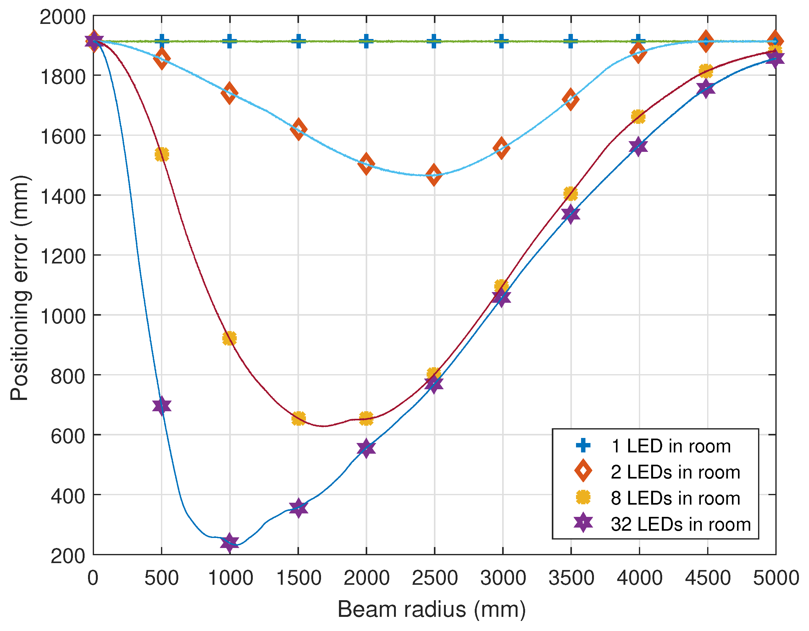
Using Algorithm 1, the variation of positioning error for increasing beam radius and number of LEDs is presented in Figure 7. It is observed that the error in positioning is reduced by increasing the number of LEDs. For , the minimum positioning error is 1907.2 mm, 1460.5 mm, 626.44 mm, and 230.99 mm, respectively. The characteristics plot in Figure 7 shows an optimal point for performance between regions of low beam radius and regions of high beam radius. This is because, at low beam radius, there are no overlaps between the LED beams and the probability that the receiver is outside the region of coverage of the beams is higher. As the low beam radius increases, this probability reduces, so the positioning error also reduces. As the overlap starts, the positioning error reduces further until the performance is optimal. However, as the beam radius continues to increase, the overlap regions also keep increasing and the non-overlapping regions reduce until every part on the room is identified as one single overlap region and the positioning error is high.
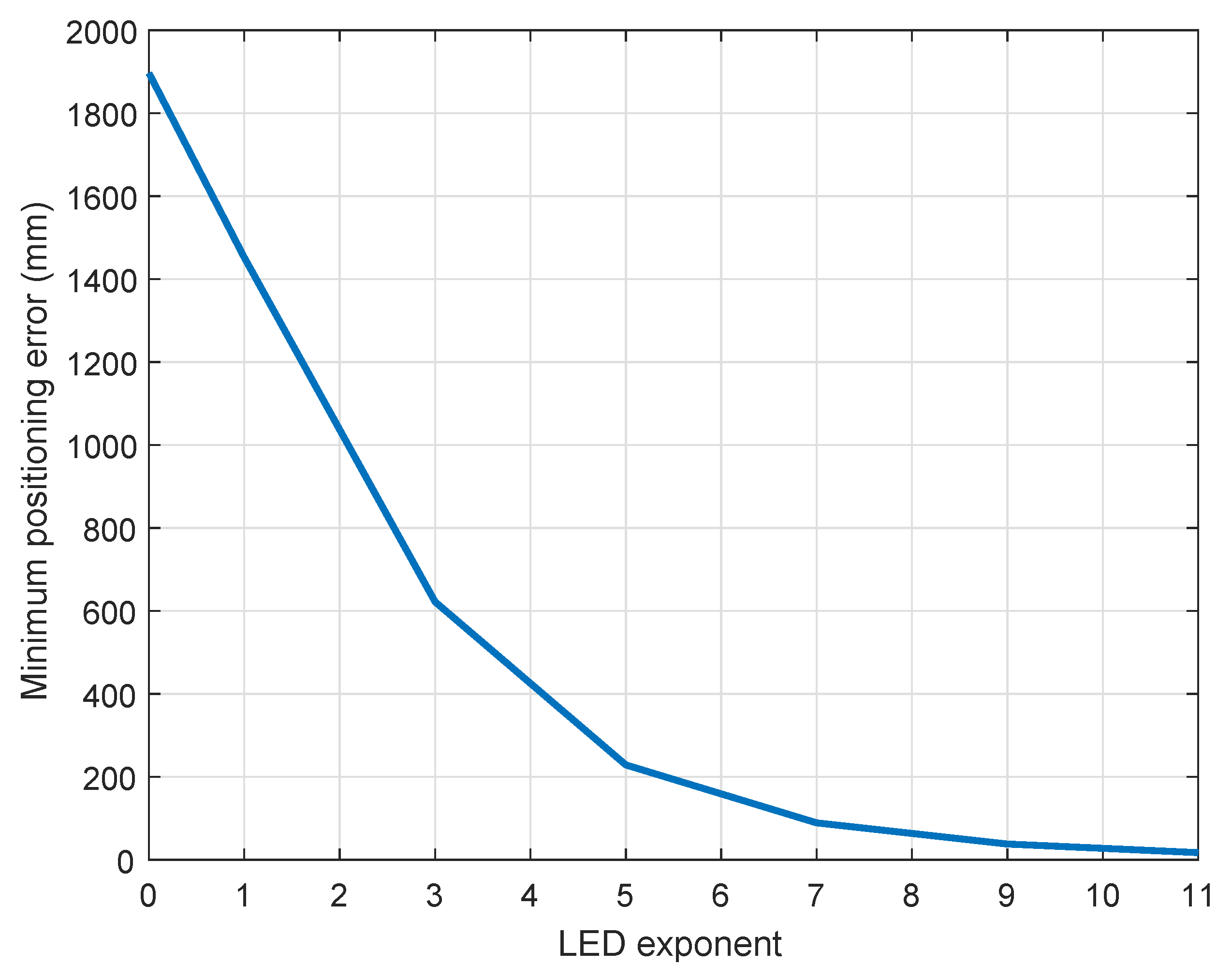
The trend in Figure 8 shows that the minimum positioning error reduces as the number of LEDs represented as the LED exponent increases. It is deduced that the positioning error reduces to 27.6 mm at an LED exponent of 10 which corresponds to 1024 LEDs in the room. Perhaps in some scenarios, installing 1024 uniquely identifiable LEDs in a room is not feasible and will increase installation cost. This increased installation cost is prevented by choosing the desired accuracy based on specific applications. For instance, for human positioning, since the average shoulder breadth of a person is between 450 mm and 600 mm [87], a system with this range of positioning error will prove accurate enough. Therefore, from Figure 8, the number of LEDs required for accurate human positioning is between 8 and 16, which is not only feasible but also keeps the system inexpensive.
The information related to the number of LEDs and beam radius that provide the desired positioning accuracy, given in Figure 7 and Figure 8, is used to estimate the correct threshold angle using (24) for minimal positioning delays. For practical purposes, this threshold angle value is used to determine the desired half angle for an LED using (13). In the design of an LED-based indoor positioning system, the available number of LEDs and desired positioning error can be maintained while the LED type is selected based on the desired threshold angle that prevents delays as presented in subsequent sections.
5.3. PDR vs. BER Relationship
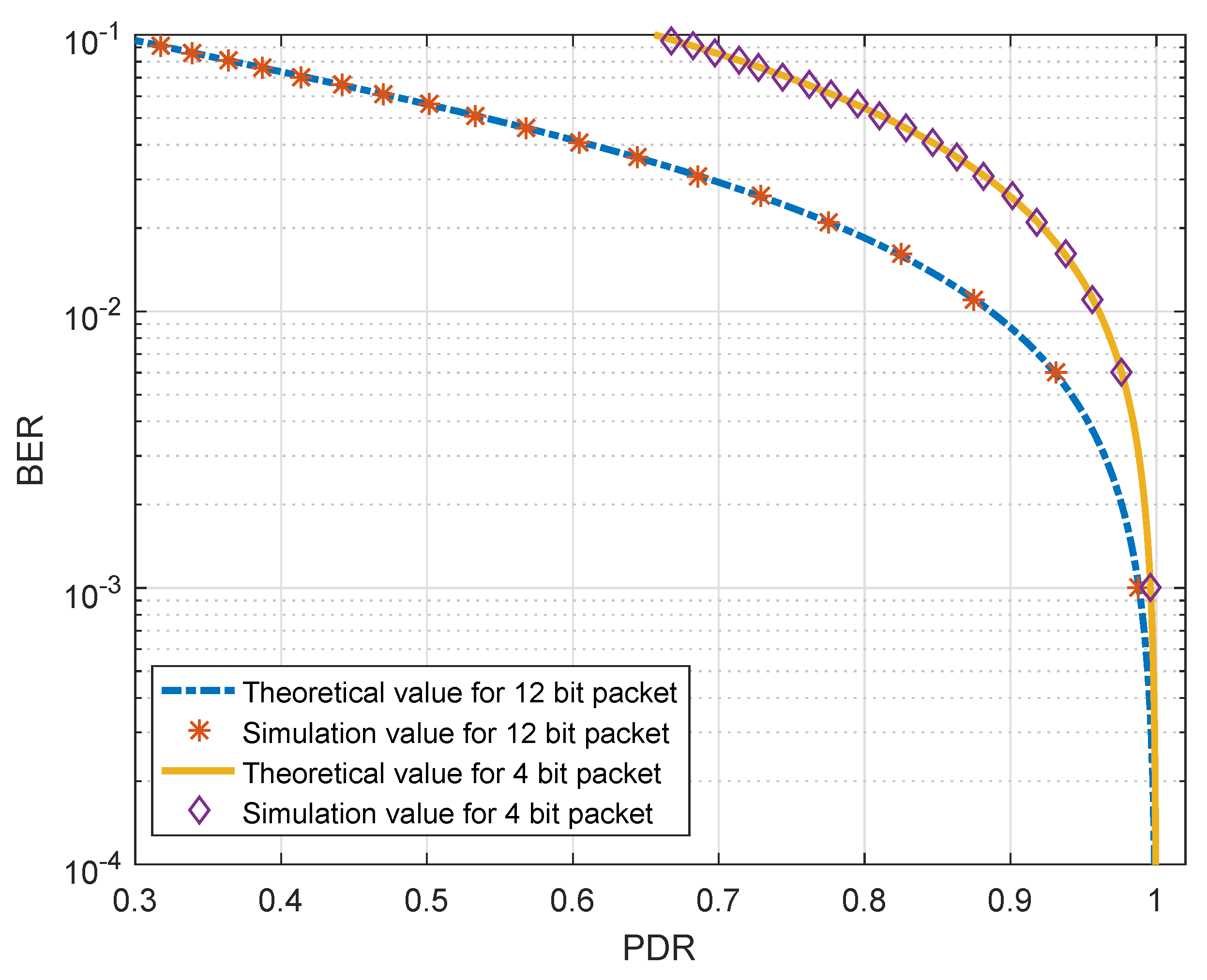
Here we present a validation of the PDR and BER relationship proposed in (11). This is done by comparing the theoretical performance of the system with the performance using the simulation. By varying BER between and with steps of , and substituting the values in (11), the theoretical curve shown in Figure 9 is plotted. The simulation values are derived using the values of the BER with increments of as the probability of bits in error in an optical channel using MATLAB software. Five hundred thousand packets are sent and the number of uncorrupted packets received is counted, the PDR is calculated as the ratio of the number of uncorrupted packets received to the total number of packets transmitted.
This takes account of the packet-based synchronization protocol which is implemented in hardware such that any packet which is not received correctly is discarded [85]. The illustration of the comparison is presented in the semi-logarithmic plot of Figure 9.
The simulation is done using the popular 12-bit Sony infrared packet [88] and a novel 4-bit packet designed in Reference [85]. In both cases, the curves validate the relationship between BER, PDR, and the number of bits in a packet as presented in (11). In terms of the performance of the packets, by comparing the two curves in Figure 9, the 4-bit packets provide a higher PDR for high BER values. Therefore, it has a faster rate of determining positioning. The 12-bit curve has low PDR values at high BER which implies that packets are easily discarded under conditions which result in high BER. Examples of these conditions are low SNR at optical boundaries and tilted receivers. Therefore, indoor positioning protocols are to be designed with the lowest possible number of bits to avoid unnecessary delays due to packet loss under the conditions. Another way to avoid the delay is to define minimum PDR conditions at the receiver. This results in a receiver-defined optical boundary as discussed in Section 3.2 and the effect is quantified in Section 5.5.
5.4. Effect of Encoding Duration on BER
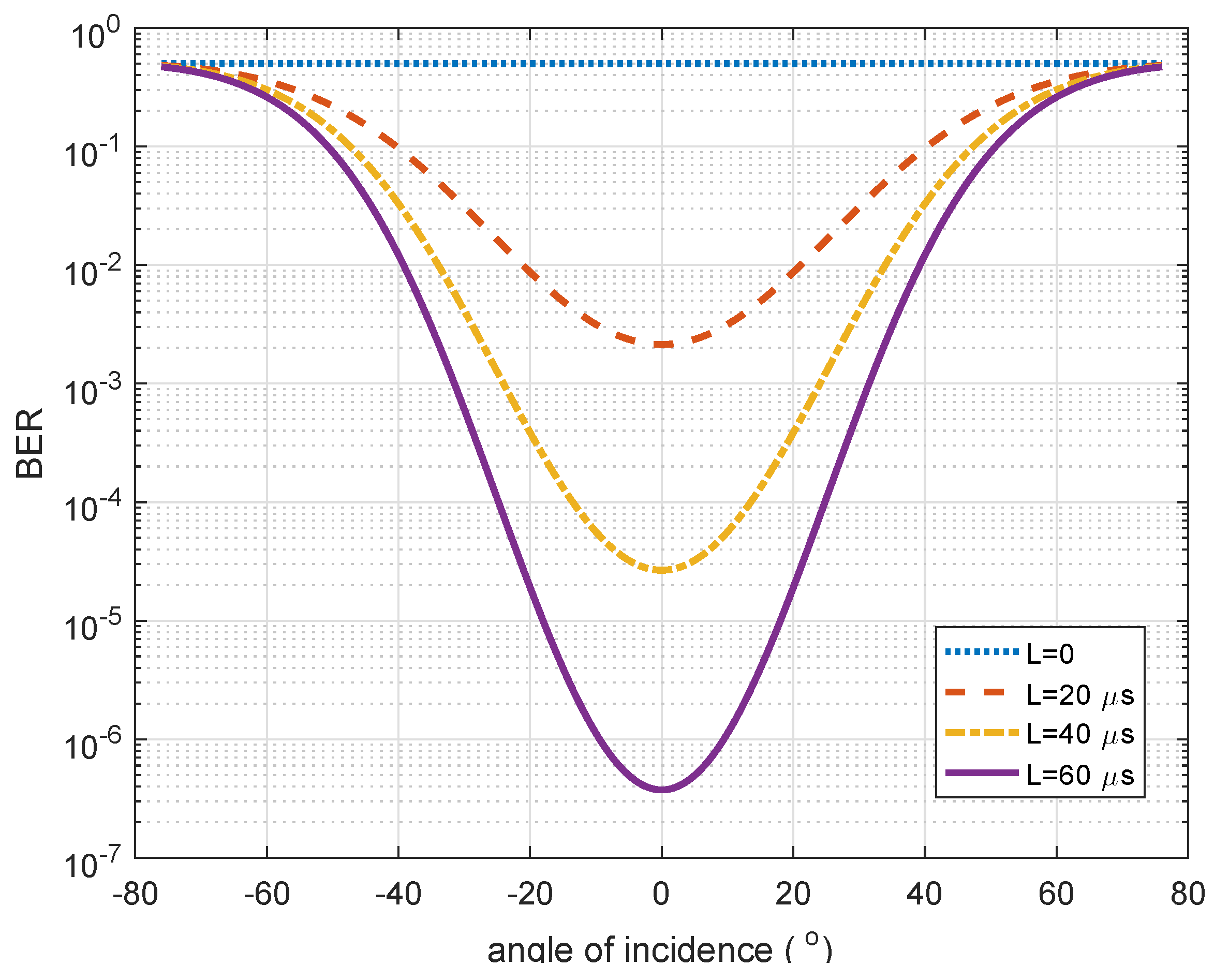
By maintaining the receiver noise at the value obtained in Section 5.1, and as the receiver moves on a horizontal plane (Figure 2), the LED data is encoded using BPC for various values of pulse duration L. As L is increased from 0 to 60 s, the BER increases as the mobile receiver moves from an incidence angle of to as shown in Figure 10. Two key pieces of information are drawn from the Figure 10. The first is the effect of the encoding duration on BER. As the value of L increases, the minimum BER also reduces and the range of incidence angles for which is an acceptable BER increases. The second piece of information is about the range of incident angles with acceptable BER values. From Figure 10, if no threshold is defined at the receiver, as the mobile receiver moves towards regions where the angle of incidence is above , the BER value becomes greater than and the PDR is less than 1 (see Figure 9). Therefore according to (14), the positioning time is increased. As the mobile receiver approaches the full angle (), the BER increases further, which causes much more of a delay in positioning time. To address this delay, a desired PDR value which corresponds to an optical threshold angle is set. For explanation purposes, let a minimum PDR value be selected such that when packets starts getting discarded (say two out of every 10 so that ), the receiver defines a boundary. A plot of the incidence angle above which the BER does not meet the conditions set out in Section 5.3 is presented in Figure 11.
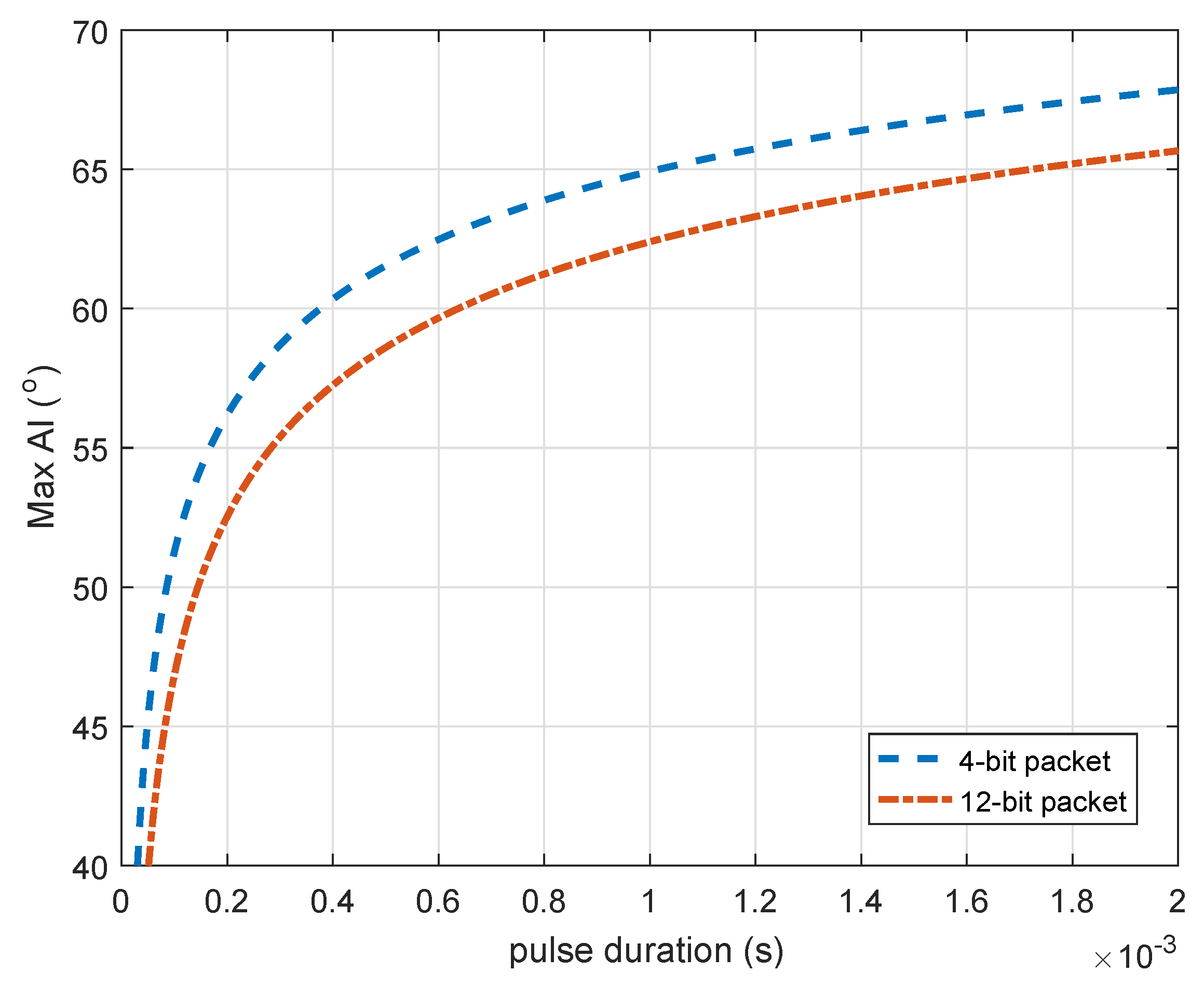
The result in Figure 11 shows the maximum angular displacement of the receiver from the transmitter at different encoded pulse durations to keep the PDR above 0.8. For a pulse duration of s, a threshold angle of about gives a PDR above 0.8 and for a pulse duration of s, the threshold angle for the same PDR is for the 12-bit protocol and for the 4-bit protocol. By using this strategy in the design of the positioning system, the positioning time is defined according to (14) thereby reducing positioning delays.
5.5. Defined Threshold Angle to Reduce for Positioning Delay
In this section, the effect of a defined threshold angle is presented in terms of positioning time. This is because the positioning time presents information on the practicability of the positioning system. Given that the average walking rate of a person is about 1 m/s [89], the desired range of positioning time will be below 1 s.
For a single LED transmitting packets where bits are encoded with a pulse length L between 0 to 1 ms, the APTs are presented in Figure 12. It shows the APT when optical boundaries are defined at the threshold angle and the APT when they are defined at the full angle as explained in Section 4.2 using 4-bit and 12-bit packets in (17). The results show that the APT generally increases with an increase in encoding pulse duration. However, for the 12-bit packet, the APT is initially very high as a result of the high BER when the pulse duration is low. At s, the APT for the threshold angle defined optical boundary system is 11 ms for 12-bit packets and 3 ms for 4-bits packets, and for the conventional system it is s for 12-bit packets and 40 ms for 4-bit packets.
When a two-LED overlap region is considered, for a cycle time of 72 ms where the minimum APT occurs, the boundary defined receiver maintains the positioning time of the 4-bit packets at ms instead of ms, and for the 12-bit packets it is maintained at s instead of 388 s as presented in Figure 13 and Figure 14. The implication of this is that the conventional full angle cannot be used to define boundaries for the overlap based system. Delays of over 1 s (of about 5 s and 388 s) renders the positioning technique unusable. Therefore, a receiver based threshold angle must be implemented with the IPS. This is because the use of threshold angle prevents the receiver from persistent delays caused by high BER, where PDR falls below the acceptable rate .
5.6. Defining Optical Boundaries to Compensate for Receiver Tilt
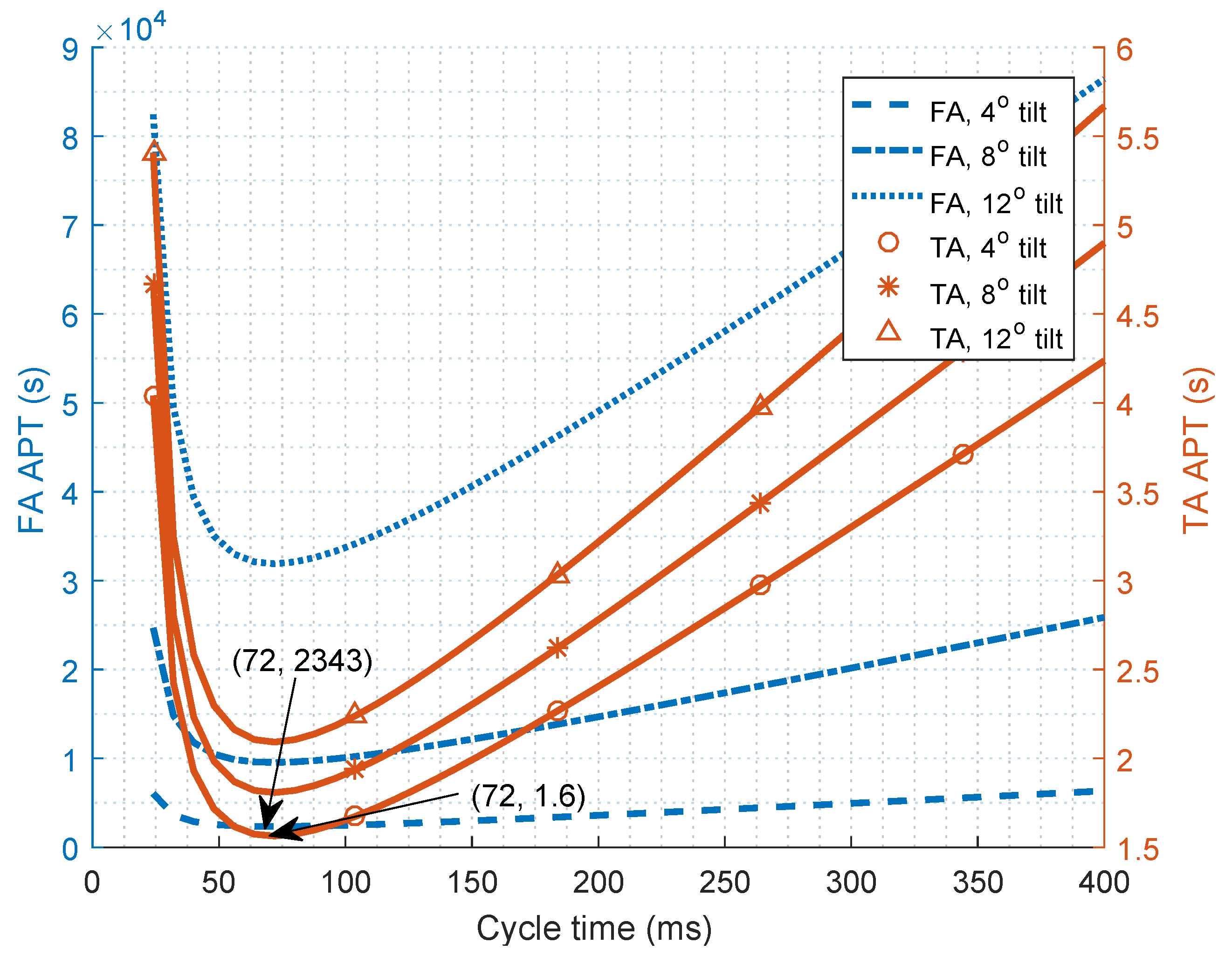
The results in Section 5.5 consider a horizontal receiver in parallel to the plane of the transmitter. However, in reality, the receiver could be tilted. When tilt occurs, the BER, especially at the boundary region, worsens. At the full angle, this poor BER causes a greater delay in receiving packets which carry positioning information and thereby causes a delay in the positioning time. Repeating the process of Section 5.5 and including , , and angle of tilt in the angle of incidence according to (22), the positioning times are presented in Figure 15 and Figure 16 for the 4-bit and 12-bit packets.
The characteristics plots in Figure 13, Figure 14 and Figure 15 show optimal cycle times for low APT between regions of low cycle times and high cycle times. This is due to two occurrences. Firstly, at very low cycle times, packets are not adequately separated to allow for pseudo-orthogonality using PDM [66]. The probability of collision in this region is high, and the average positioning time is high in this region due to packets lost in collisions. However, if the cycle times are significantly increased (at very high cycle times), there is a long wait before the packets are received. The trade-off between the delay caused by high probability of collisions at low cycle times and the delay caused by long waits at high cycle times lead to the optimal cycle times.
The effect of tilt in terms of positioning time shows that by defining the optical boundary, for a tilt which is expected in a person walking, the APT is s for the 4-bit and s for the the 12-bit packets. Whereas, if the conventional full angle is used, the APT increases to s for the 4-bit packets and 2343 s for the 12-bit packets. This shows a large amount of positioning time delay when boundary conditions are not specified at the optical receiver. For a angle of tilt, using the 4-bit packet, the positioning time is s, which still meets the criteria for human positioning. Therefore, defining the threshold angle based optical boundary makes the receiver robust and resistant to little tilts which could be experienced in practical scenarios.
6. Conclusions
The boundary of LED footprints plays a vital role in position estimation of proximity LED-based IPS. In this work, the boundary of an LED footprint is defined based on the properties of a mobile receiver. This technique can be used in RSS, AoA, and fingerprinting positioning systems that involve overlap of LED beams and use the PDM multiplexing technique. This work shows that by properly defining the optical boundary, unnecessary delays in positioning time can be prevented. It first establishes and validates a relationship between the BER and PDR of packets received at the receiver and then shows the effect of encoding protocol design on the BER. These relationships are used to show how signal quality deterioration due to undefined optical boundary affects the positioning time of the IPS. For a single LED transmitter, the defined optical boundary reduced the positioning delay by a factor of 13 for a 4-bit packet and by 230 for 12-bit packets. When overlap, which is used to improve positioning accuracy, is considered, the defined optical boundary reduces the positioning delay by a factor of 12 and 287 for 4-bit and 12-bit packets, respectively. The effect of a tilted receiver is also studied, and this work shows that for a tilt, the positioning time is improved by a factor of 22 and 1464 for 4-bit and 12-bit packets, respectively. In conclusion, full angle boundaries waste positioning time, and hence are not usable for LED based positioning. In terms of positioning accuracy, the use of a threshold angle maintains a systems positioning accuracy by changing the number of LEDs required. With 32 LEDs, a positioning error of mm is achieved, and the error reduces as the number of LEDs increases. This work has shown that a desired positioning accuracy can be achieved while using a receiver based threshold angle in the positioning system design to reduce positioning delay significantly. This facilitates the design of a simple lightweight wearable receiver for indoor positioning.
For future work, the effect of using other encoding schemes to design the positioning protocol will be determined.
Author Contributions
Conceptualization, O.R.P. and S.S.; Formal analysis, O.R.P., S.S., W.O.P. and R.R.-I.; Funding acquisition, S.S.; Investigation, O.R.P., S.S., W.O.P. and R.R.-I.; Methodology, O.R.P., S.S., W.O.P. and R.R.-I.; Project administration, S.S., W.O.P. and R.R.-I.; Resources, O.R.P.; Software, O.R.P.; Supervision, S.S., W.O.P. and R.R.-I.; Validation, O.R.P.; Visualization, O.R.P.; Writing original draft, O.R.P.; Writing review and editing, S.S., W.O.P. and R.R.-I.
Funding
This research received no external funding.
Acknowledgments
The authors would like to appreciate the support for this research work from the School of Engineering and Built Environment of Glasgow Caledonian University through the University sponsored research studentship.
Conflicts of Interest
The authors declare no conflict of interest.
Abbreviations
The following abbreviations are used in this manuscript:
| LED | Light emitting diode |
| IPS | Indoor positioning system |
| RF | Radio frequency |
| RSS | Received signal strength |
| AoA | Angle of arrival |
| ToA | Time of arrival |
| TDoA | Time difference of arrival |
| PDoA | Phase difference of arrival |
| ES | Experimental setup |
| APD | Avalanche photo-diode |
| TIA | Trans-impedance amplifier |
| LNA | Low noise amplifier |
| PC | Personal computer |
| OWC | Optical wireless communication |
| MLEM | Multiple LED estimation model |
| PDM | Packet duration multiplexing |
| PD | Photo detector |
| BER | Bit error rate |
| SNR | signal-to-noise ratio |
| OOK | On-off keying |
| PDR | Packet delivery ratio |
| PWM | Pulse width modulation |
| BPC | Biphase coding |
| APT | Average positioning time |
References
- Hwang, I.; Jang, Y.J. Process Mining to Discover Shoppers? Pathways at a Fashion Retail Store Using a WiFi-Base Indoor Positioning System. IEEE Trans. Autom. Sci. Eng. 2017, 14, 1786–1792. [Google Scholar] [CrossRef]
- Rantakokko, J.; Rydell, J.; Strömbäck, P.; Händel, P.; Callmer, J.; Törnqvist, D.; Gustafsson, F.; Jobs, M.; Gruden, M. Accurate and reliable soldier and first responder indoor positioning: Multisensor systems and cooperative localization. IEEE Wirel. Commun. 2011, 18, 10–18. [Google Scholar] [CrossRef]
- Zhuang, Y.; Hua, L.; Qi, L.; Yang, J.; Cao, P.; Cao, Y.; Wu, Y.; Thompson, J.; Haas, H. A survey of positioning systems using visible LED lights. IEEE Commun. Surv. Tutor. 2018, 20, 1963–1988. [Google Scholar] [CrossRef]
- Correa, A.; Barcelo, M.; Morell, A.; Vicario, J.L. A review of pedestrian indoor positioning systems for mass market applications. Sensors 2017, 17, 1927. [Google Scholar] [CrossRef] [PubMed]
- Fang, J.; Yang, Z.; Long, S.; Wu, Z.; Zhao, X.; Liang, F.; Jiang, Z.L.; Chen, Z. High-speed indoor navigation system based on visible light and mobile phone. IEEE Photonics J. 2017, 9, 1–11. [Google Scholar] [CrossRef]
- Rabadan, J.; Guerra, V.; Rodríguez, R.; Rufo, J.; Luna-Rivera, M.; Perez-Jimenez, R. Hybrid visible light and ultrasound-based sensor for distance estimation. Sensors 2017, 17, 330. [Google Scholar] [CrossRef] [PubMed]
- Wu, F.; Liang, Y.; Fu, Y.; Geng, C. A New Indoor Positioning System Using Artificial Encoded Magnetic Fields. J. Navig. 2018, 71, 299–316. [Google Scholar] [CrossRef]
- Kim, H.S.; Kim, D.R.; Yang, S.H.; Son, Y.H.; Han, S.K. An indoor visible light communication positioning system using a RF carrier allocation technique. J. Lightw. Technol. 2013, 31, 134–144. [Google Scholar] [CrossRef]
- Nakajima, M.; Haruyama, S. New indoor navigation system for visually impaired people using visible light communication. EURASIP J. Wirel. Commun. Netw. 2013, 2013, 1–10. [Google Scholar] [CrossRef]
- Vongkulbhisal, J.; Chantaramolee, B.; Zhao, Y.; Mohammed, W.S. A fingerprinting-based indoor localization system using intensity modulation of light emitting diodes. Microw. Opt. Technol. Lett. 2012, 54, 1218–1227. [Google Scholar] [CrossRef]
- Cossu, G.; Presi, M.; Corsini, R.; Choudhury, P.; Khalid, A.M.; Ciaramella, E. A visible light localization aided optical wireless system. In Proceedings of the IEEE GLOBECOM Workshops (GC Wkshps), Houston, TX, USA, 5–9 December 2011; pp. 802–807. [Google Scholar]
- Del Campo-Jimenez, G.; Perandones, J.M.; Lopez-Hernandez, F.J. A VLC-based beacon location system for mobile applications. In Proceedings of the IEEE International Conference on Localization and GNSS (ICL-GNSS), Turin, Italy, 25–27 June 2013; pp. 1–4. [Google Scholar]
- Xu, W.; Wang, J.; Shen, H.; Zhang, H.; You, X. Indoor positioning for multiphotodiode device using visible-light communications. IEEE Photonics J. 2016, 8, 1–11. [Google Scholar] [CrossRef]
- Zhou, Z.; Kavehrad, M.; Deng, P. Indoor positioning algorithm using light-emitting diode visible light communications. Opt. Eng. 2012, 51, 085009. [Google Scholar] [CrossRef]
- Luo, J.; Fan, L.; Li, H. Indoor Positioning Systems Based on Visible Light Communication: State of the Art. IEEE Commun. Surv. Tutor. 2017, 19, 2871–2893. [Google Scholar] [CrossRef]
- Dividis, K. Design and Prototyping of a Visible Light Indoor Positioning System; Stan Ackermans Institute: Delft, The Netherlands, 2007. [Google Scholar]
- Zhang, W.; Kavehrad, M. A 2-D indoor localization system based on visible light LED. In Proceedings of the IEEE Photonics Society Summer Topical Meeting Series, Seattle, WA, USA, 9–11 July 2012; pp. 80–81. [Google Scholar]
- Sertthin, C.; Tsuji, E.; Nakagawa, M.; Kuwano, S.; Watanabe, K. A switching estimated receiver position scheme for visible light based indoor positioning system. In Proceedings of the 4th IEEE International Symposium on Wireless Pervasive Computing (ISWPC), Melbourne, Australia, 11–13 February 2009; pp. 1–5. [Google Scholar]
- Lee, Y.U.; Kavehrad, M. Long-range indoor hybrid localization system design with visible light communications and wireless network. In Proceedings of the IEEE Photonics Society Summer Topical Meeting Series, Seattle, WA, USA, 9–11 July 2012; pp. 82–83. [Google Scholar]
- Jung, S.Y.; Hann, S.; Park, S.; Park, C.S. Optical wireless indoor positioning system using light emitting diode ceiling lights. Microw. Opt. Technol. Lett. 2012, 54, 1622–1626. [Google Scholar] [CrossRef]
- Lim, J. Ubiquitous 3D positioning systems by LED-based visible light communications. IEEE Wirel. Commun. 2015, 22, 80–85. [Google Scholar] [CrossRef]
- Kail, G.; Maechler, P.; Preyss, N.; Burg, A. Robust asynchronous indoor localization using LED lighting. In Proceedings of the IEEE International Conference on Acoustics, Speech and Signal Processing (ICASSP), Florence, Italy, 4–9 May 2014; pp. 1866–1870. [Google Scholar]
- Wang, C.; Wang, L.; Chi, X.; Liu, S.; Shi, W.; Deng, J. The research of indoor positioning based on visible light communication. China Commun. 2015, 12, 85–92. [Google Scholar] [CrossRef]
- Kim, B.Y.; Cho, J.S.; Park, Y.; Kim, K.D. Implementation of indoor positioning using LED and dual PC cameras. In Proceedings of the 4th IEEE International Conference on Ubiquitous and Future Networks (ICUFN), Phuket, Thailand, 4–6 July 2012; pp. 476–477. [Google Scholar]
- Biagi, M.; Vegni, A.M.; Little, T.D. LAT indoor MIMO-VLC Localize, access and transmit. In Proceedings of the IEEE International Workshop on Optical Wireless Communications (IWOW), Pisa, Italy, 22 Octobet 2012; pp. 1–3. [Google Scholar]
- Vegni, A.M.; Biagi, M. An indoor localization algorithm in a small-cell LED-based lighting system. In Proceedings of the IEEE International Conference on Indoor Positioning and Indoor Navigation (IPIN) 2012, Sydney, Australia, 13–15 November 2012; pp. 1–7. [Google Scholar]
- Yang, S.H.; Kim, D.R.; Kim, H.S.; Son, Y.H.; Han, S.K. Indoor positioning system based on visible light using location code. In Proceedings of the IEEE Fourth International Conference on Communications and Electronics (ICCE), Hue, Vietnam, 1–3 August 2012; pp. 360–363. [Google Scholar]
- Yoshino, M.; Haruyama, S.; Nakagawa, M. High-accuracy positioning system using visible LED lights and image sensor. In Proceedings of the IEEE Radio and Wireless Symposium, Orlando, FL, USA, 22–24 January 2008; pp. 439–442. [Google Scholar]
- Tanaka, T.; Haruyama, S. New position detection method using image sensor and visible light LEDs. In Proceedings of the Second IEEE International Conference on Machine Vision (ICMV), Dubai, UAE, 28–30 December 2009; pp. 150–153. [Google Scholar]
- Rahman, M.S.; Haque, M.M.; Kim, K.D. Indoor positioning by LED visible light communication and image sensors. Int. J. Electr. Comput. Eng. 2011, 1, 161–170. [Google Scholar] [CrossRef]
- Xu, Y.; Zhao, J.; Shi, J.; Chi, N. Reversed Three-Dimensional Visible Light Indoor Positioning Utilizing Annular Receivers with Multi-Photodiodes. Sensors 2016, 16, 1254. [Google Scholar] [CrossRef]
- Nasar, A.W.; Sohail, M.; Bokhari, S.M.A.; Kasi, J.K.; Kasi, A.K. Implementation of visible light communication based system for indoor positioning. MATTER Int. J. Sci. Technol. 2017, 3, 67–80. [Google Scholar] [CrossRef]
- Peng, Q.; Guan, W.; Wu, Y.; Cai, Y.; Xie, C.; Wang, P. Three-dimensional high-precision indoor positioning strategy using Tabu search based on visible light communication. Opt. Eng. 2018, 57, 016101. [Google Scholar] [CrossRef]
- Jung, S.Y.; Hann, S.; Park, C.S. TDOA-based optical wireless indoor localization using LED ceiling lamps. IEEE Trans. Consum. Electron. 2011, 57, 1592–1597. [Google Scholar] [CrossRef]
- Do, T.H.; Yoo, M. TDOA-based indoor positioning using visible light. Photonic Netw. Commun. 2014, 27, 80–88. [Google Scholar] [CrossRef]
- Choi, Y.H.; Park, I.H.; Kim, Y.H.; Kim, J.Y. Novel LBS technique based on visible light communications. In Proceedings of the IEEE International Conference on Consumer Electronics (ICCE), Las Vegas, NV, USA, 13–16 January 2012; pp. 576–577. [Google Scholar]
- Nah, J.; Parthiban, R.; Jaward, M. Visible light communications localization using TDOA-based coherent heterodyne detection. In Proceedings of the 4th IEEE International Conference on Photonics (ICP), Melaka, Malaysia, 28–30 October 2013; pp. 247–249. [Google Scholar]
- Panta, K.; Armstrong, J. Indoor localisation using white LEDs. Electron. Lett. 2012, 48, 228–230. [Google Scholar] [CrossRef]
- Kuo, Y.S.; Pannuto, P.; Hsiao, K.J.; Dutta, P. Luxapose: Indoor positioning with mobile phones and visible light. In Proceedings of the 20th Annual International Conference on Mobile Computing and Networking, Maui, HI, USA, 7–11 September 2014; pp. 447–458. [Google Scholar]
- Lee, S.; Jung, S.Y. Location awareness using angle-of-arrival based circular-PD-array for visible light communication. In Proceedings of the 18th Asia-Pacific Conference on Communications (APCC), Jeju Island, Korea, 15–17 October 2012; pp. 480–485. [Google Scholar]
- Liu, X.; Makino, H.; Maeda, Y. Basic study on indoor location estimation using visible light communication platform. In Proceedings of the 30th IEEE Annual International Conference of the Engineering in Medicine and Biology Society, Vancouver, BC, Canada, 20–25 August 2008; pp. 2377–2380. [Google Scholar]
- Kim, H.S.; Kim, D.R.; Yang, S.H.; Son, Y.H.; Han, S.K. Inter-cell interference mitigation and indoor positioning system based on carrier allocation visible light communication. In Proceedings of the 5th International Conference on Signal Processing and Communication Systems (ICSPCS), Honolulu, HI, USA, 12–14 December 2011; pp. 1–7. [Google Scholar]
- Arafa, A.; Dalmiya, S.; Klukas, R.; Holzman, J.F. Angle-of-arrival reception for optical wireless location technology. Opt. Express 2015, 23, 7755–7766. [Google Scholar] [CrossRef] [PubMed]
- Yang, S.H.; Jung, E.M.; Han, S.K. Indoor location estimation based on LED visible light communication using multiple optical receivers. IEEE Commun. Lett. 2013, 17, 1834–1837. [Google Scholar] [CrossRef]
- Luo, P.; Zhang, M.; Zhang, X.; Cai, G.; Han, D.; Li, Q. An indoor visible light communication positioning system using dual-tone multi-frequency technique. In Proceedings of the 2nd International Workshop on Optical Wireless Communications (IWOW), Newcastle upon Tyne, UK, 21 October 2013; pp. 25–29. [Google Scholar]
- Jung, S.Y.; Choi, C.K.; Heo, S.H.; Lee, S.R.; Park, C.S. Received signal strength ratio based optical wireless indoor localization using light emitting diodes for illumination. In Proceedings of the IEEE International Conference on Consumer Electronics (ICCE), Las Vegas, NV, USA, 11–14 January 2013; pp. 63–64. [Google Scholar]
- Li, L.; Hu, P.; Peng, C.; Shen, G.; Zhao, F. Epsilon: A visible light based positioning system. In Proceedings of the 11th USENIX Symposium on Networked Systems Design and Implementation (NSDI 14), Seattle, WA, USA, 2–4 April 2014; pp. 331–343. [Google Scholar]
- Zhang, W.; Chowdhury, M.S.; Kavehrad, M. Asynchronous indoor positioning system based on visible light communications. Opt. Eng. 2014, 53, 045105. [Google Scholar] [CrossRef]
- Rahaim, M.; Prince, G.B.; Little, T.D. State estimation and motion tracking for spatially diverse VLC networks. In Proceedings of the IEEE Globecom Workshops (GC Wkshps), Anaheim, CA, USA, 3–7 December 2012; pp. 1249–1253. [Google Scholar]
- Aminikashani, M.; Gu, W.; Kavehrad, M. Indoor positioning with OFDM visible light communications. In Proceedings of the 13th IEEE Annual Consumer Communications & Networking Conference (CCNC), Las Vegas, NV, USA, 9–12 January 2016; pp. 505–510. [Google Scholar]
- Yamaguchi, S.; Mai, V.V.; Thang, T.C.; Pham, A.T. Design and performance evaluation of VLC indoor positioning system using optical orthogonal codes. In Proceedings of the IEEE Fifth International Conference on Communications and Electronics (ICCE), Danang, Vietnam, 30 July–1 August 2014; pp. 54–59. [Google Scholar]
- Kim, Y.; Hwang, J.; Lee, J.; Yoo, M. Position estimation algorithm based on tracking of received light intensity for indoor visible light communication systems. In Proceedings of the Third International Conference on Ubiquitous and Future Networks (ICUFN), Dalian, China, 15–17 June 2011; pp. 131–134. [Google Scholar]
- Gu, W.; Zhang, W.; Wang, J.; Kashani, M.; Kavehrad, M. Three dimensional indoor positioning based on visible light with gaussian mixture sigma-point particle filter technique. In Proceedings of the Broadband Access Communication Technologies IX, San Francisco, CA, USA, 7–12 February 2015. [Google Scholar]
- Gu, W.; Aminikashani, M.; Deng, P.; Kavehrad, M. Impact of multipath reflections on the performance of indoor visible light positioning systems. J. Lightw. Technol. 2016, 34, 2578–2587. [Google Scholar] [CrossRef]
- Jeong, E.M.; Yang, S.H.; Kim, H.S.; Han, S.K. Tilted receiver angle error compensated indoor positioning system based on visible light communication. Electron. Lett. 2013, 49, 890–892. [Google Scholar] [CrossRef]
- Luo, Z.; Zhang, W.; Zhou, G. Improved Spring Model-Based Collaborative Indoor Visible Light Positioning; Springer: Berlin, Germany, 2016; Volume 23, pp. 479–486. [Google Scholar]
- Pergoloni, S.; Mohamadi, Z.; Vegni, A.M.; Ghassemlooy, Z.; Biagi, M. Metameric Indoor Localization Schemes Using Visible Lights. J. Lightw. Technol. 2017, 35, 2933–2942. [Google Scholar] [CrossRef]
- Zhang, R.; Zhong, W.D.; Kemao, Q.; Zhang, S. A Single LED Positioning System Based on Circle Projection. IEEE Photonics J. 2017, 9, 1–9. [Google Scholar] [CrossRef]
- Nakazawa, Y.; Makino, H.; Nishimori, K.; Wakatsuki, D.; Komagata, H. Indoor positioning using a high-speed, fish-eye lens-equipped camera in visible light communication. In Proceedings of the IEEE International Conference on Indoor Positioning and Indoor Navigation (IPIN), Montbeliard-Belfort, France, 28–31 October 2013; pp. 1–8. [Google Scholar]
- Yang, Z.; Wang, Z.; Zhang, J.; Huang, C.; Zhang, Q. Wearables can afford: Light-weight indoor positioning with visible light. In Proceedings of the 13th Annual International Conference on Mobile Systems, Applications, and Services, Florence, Italy, 18–22 May 2015; pp. 317–330. [Google Scholar]
- Hossan, M.; Chowdhury, M.Z.; Islam, A.; Jang, Y.M. A novel indoor mobile localization system based on optical camera communication. Wirel. Commun. Mob. Comput. 2018, 2018, 9353428. [Google Scholar] [CrossRef]
- Zhang, R.; Zhong, W.D.; Qian, K.; Wu, D. Image Sensor Based Visible Light Positioning System with Improved Positioning Algorithm. IEEE Access 2017, 5, 6087–6094. [Google Scholar] [CrossRef]
- Chen, L.W.; Chen, C.R.; Chen, D.E. VIPS: A video-based indoor positioning system with centimeter-grade accuracy for the IoT. In Proceedings of the IEEE International Conference on Pervasive Computing and Communications Workshops (PerCom Workshops), Kona, HI, USA, 13–17 March 2017; pp. 63–65. [Google Scholar]
- Lin, B.; Ghassemlooy, Z.; Lin, C.; Tang, X.; Li, Y.; Zhang, S. An Indoor Visible Light Positioning System Based on Optical Camera Communications. IEEE Photonics Technol. Lett. 2017, 29, 579–582. [Google Scholar] [CrossRef]
- Zheng, Y.; Shen, G.; Li, L.; Zhao, C.; Li, M.; Zhao, F. Travi-navi: Self-deployable indoor navigation system. IEEE/ACM Trans. Netw. 2017, 25, 2655–2669. [Google Scholar] [CrossRef]
- Popoola, O.R.; Sinanovic, S. Design and Analysis of Collision Reduction Algorithms for LED-based Indoor Positioning with Simulation and Experimental Validation. IEEE Access 2018, 6, 10754–10770. [Google Scholar] [CrossRef]
- Di Renzo, M.; Haas, H.; Ghrayeb, A.; Sugiura, S.; Hanzo, L. Spatial modulation for generalized MIMO: Challenges, opportunities, and implementation. Proc. IEEE 2014, 102, 56–103. [Google Scholar] [CrossRef]
- Winzer, P.J.; Essiambre, R.J. Advanced optical modulation formats. Proc. IEEE 2006, 94, 952–985. [Google Scholar] [CrossRef]
- Zeng, L.; O’Brien, D.C.; Le Minh, H.; Faulkner, G.E.; Lee, K.; Jung, D.; Oh, Y.; Won, E.T. High data rate multiple input multiple output (MIMO) optical wireless communications using white LED lighting. IEEE J. Sel. Areas Commun. 2009, 27, 10754–10770. [Google Scholar] [CrossRef]
- Jalajakumari, A.V.; Xie, E.; McKendry, J.; Gu, E.; Dawson, M.D.; Haas, H.; Henderson, R.K. High-speed integrated digital to light converter for short range visible light communication. IEEE Photonics Technol. Lett. 2017, 29, 118–121. [Google Scholar] [CrossRef]
- Uysal, M.; Miramirkhani, F.; Narmanlioglu, O.; Baykas, T.; Panayirci, E. IEEE 802.15. 7r1 reference channel models for visible light communications. IEEE Commun. Mag. 2017, 55, 212–217. [Google Scholar] [CrossRef]
- Islim, M.S.; Ferreira, R.X.; He, X.; Xie, E.; Videv, S.; Viola, S.; Watson, S.; Bamiedakis, N.; Penty, R.V.; White, I.H.; et al. Towards 10 Gb/s orthogonal frequency division multiplexing-based visible light communication using a GaN violet micro-LED. Photonics Res. 2017, 5, A35–A43. [Google Scholar] [CrossRef]
- Fletcher, A.S.; Hamilton, S.A.; Moores, J.D. Undersea laser communication with narrow beams. IEEE Commun. Mag. 2015, 53, 49–55. [Google Scholar] [CrossRef]
- Zafar, F.; Bakaul, M.; Parthiban, R. Laser-Diode-Based Visible Light Communication: Toward Gigabit Class Communication. IEEE Commun. Mag. 2017, 55, 144–151. [Google Scholar] [CrossRef]
- Popoola, O.; Ogunkoya, F.; Popoola, W.; Ramirez-Iniguez, R.; Sinanović, S. Indoor localization based on multiple LEDs position estimation. In Proceedings of the 17th IEEE International Workshop on Signal Processing Advances in Wireless Communications (SPAWC), Edinburgh, UK, 3–6 July 2016; pp. 1–6. [Google Scholar]
- Lee, Y.U.; Kavehrad, M. Two hybrid positioning system design techniques with lighting LEDs and ad-hoc wireless network. IEEE Trans. Consum. Electron. 2012, 58, 1176–1184. [Google Scholar] [CrossRef]
- Ajmani, M.; Sinanović, S.; Boutaleb, T. Optical Wireless Communication Based Indoor Positioning Algorithms: Performance Optimisation and Mathematical Modelling. Computation 2019, 7, 1. [Google Scholar] [CrossRef]
- Popoola, O.R.; Popoola, W.O.; Ramirez-Iniguez, R.; Sinanovic, S. Optimization of duty cycles for LED based indoor positioning system. In Proceedings of the IEEE International Conference for Students on Applied Engineering (ICSAE), Newcastle upon Tyne, UK, 20–21 October 2016; pp. 368–372. [Google Scholar] [CrossRef]
- Gu, W.; Zhang, W.; Kavehrad, M.; Feng, L. Three-dimensional light positioning algorithm with filtering techniques for indoor environments. Opt. Eng. 2014, 53, 107107. [Google Scholar] [CrossRef]
- Ghassemlooy, Z.; Popoola, W.; Rajbhandari, S. Optical Wireless Communications: System and Channel Modelling with MATLAB®; CRC Press: Boca Raton, FL, USA, 2012. [Google Scholar]
- Dimitrov, S.; Haas, H. Principles of LED Light Communications: Towards Networked Li-Fi; Cambridge University Press: Cambridge, UK, 2015. [Google Scholar]
- Kahn, J.M.; Barry, J.R. Wireless infrared communications. Proc. IEEE 1997, 85, 265–298. [Google Scholar] [CrossRef] [Green Version]
- Freude, W.; Schmogrow, R.; Nebendahl, B.; Winter, M.; Josten, A.; Hillerkuss, D.; Koenig, S.; Meyer, J.; Dreschmann, M.; Huebner, M.; et al. Quality metrics for optical signals: Eye diagram, Q-factor, OSNR, EVM and BER. In Proceedings of the 14th IEEE International Conference on Transparent Optical Networks (ICTON), Coventry, UK, 2–5 July 2012; pp. 1–4. [Google Scholar]
- Ibrahim, M.H.; Shaban, H.A.; Aly, M.H. Effect of different weather conditions on BER performance of single-channel free space optical links. Opt.-Int. J. Light Electron Opt. 2017, 137, 291–297. [Google Scholar] [CrossRef]
- Popoola, O.R.; Popoola, W.O.; Ramirez-Iniguez, R.; Sinanović, S. Design of improved IR protocol for LED indoor positioning system. In Proceedings of the 13th International Wireless Communications and Mobile Computing Conference (IWCMC), Valencia, Spain, 26–30 June 2017; pp. 882–887. [Google Scholar]
- Semiconductors, V. Data Fotmats for IR Remote Control; Vishay: Malvern, PA, USA, 2013; pp. 7–11. [Google Scholar]
- Masson, A.E.; Hignett, S.; Gyi, D.E. Anthropometric Study to Understand Body Size and Shape for Plus Size People at Work. Procedia Manuf. 2015, 3, 5647–5654. [Google Scholar] [CrossRef] [Green Version]
- Augmented, S.L. Application Note: Implementation of Transmitters and Receivers for Infrared Remote Control Protocols with MCUs of the STM32F0 and STM32F3 Series. 2016. Available online: www.st.com (accessed on 11 November 2017).
- Albrecht, H.; Wötzel, C.; Erasmus, L.; Kleinpeter, M.; König, N.; Pöllmann, W. Day-to-day variability of maximum walking distance in MS patients can mislead to relevant changes in the Expanded Disability Status Scale (EDSS): Average walking speed is a more constant parameter. Mult. Scler. 2001, 7, 105–109. [Google Scholar] [CrossRef]
Figure 1.
Illustration of top view of room showing the overlap of LED beams and tilted receiver tilting away from the transmitter where is the angle of incidence and x is the horizontal displacement. (a) four similar LEDs, (b) four unique LEDs, (c) illustration of angle of tilt .
Figure 1.
Illustration of top view of room showing the overlap of LED beams and tilted receiver tilting away from the transmitter where is the angle of incidence and x is the horizontal displacement. (a) four similar LEDs, (b) four unique LEDs, (c) illustration of angle of tilt .

Figure 2.
Optical positioning system with LED transmitter and photo-detector (PD) receiver.

Figure 3.
Normalized received optical power for LEDs with a half angle of 10 and and a horizontally moving receiver on a plane at a distance 3 m from the transmitter.
Figure 3.
Normalized received optical power for LEDs with a half angle of 10 and and a horizontally moving receiver on a plane at a distance 3 m from the transmitter.

Figure 4.
Received optical power from LED for a horizontally moving receiver when tilted at , , , and .
Figure 4.
Received optical power from LED for a horizontally moving receiver when tilted at , , , and .

Figure 5.
Set-ups to show the effect of full angle on positioning. (a) Effect in a single LED positioning system, (b) the effect in the overlap system with two identical LEDs.
Figure 5.
Set-ups to show the effect of full angle on positioning. (a) Effect in a single LED positioning system, (b) the effect in the overlap system with two identical LEDs.

Figure 6.
Experimental setup for noise determination. A: Transmitter electronic module, B: Transmitter LED on stand, C: Power supply unit, D: Oscilloscope for measurement, E: Receiver electronics module, F: Receiver PD on stand.
Figure 6.
Experimental setup for noise determination. A: Transmitter electronic module, B: Transmitter LED on stand, C: Power supply unit, D: Oscilloscope for measurement, E: Receiver electronics module, F: Receiver PD on stand.

Figure 7.
Positioning error as the beam radius and the number of LEDs in a room are increased.

Figure 8.
Representation of minimal positioning error for increasing number of LEDs presented as the LED exponent factor as defined in (23)
Figure 8.
Representation of minimal positioning error for increasing number of LEDs presented as the LED exponent factor as defined in (23)

Figure 9.
Validation of the packet delivery ratio (PDR) and bit error rate (BER) relationship in (11) using 4 bit and 12 bit protocols.
Figure 9.
Validation of the packet delivery ratio (PDR) and bit error rate (BER) relationship in (11) using 4 bit and 12 bit protocols.

Figure 10.
BER vs. angle of incidence for increasing BPC pulse length L and a minimum PDR of 0.8.

Figure 11.
Maximum angle of incidence (Max AI) for encoding pulse duration between 0 and 2 ms.

Figure 12.
Reduction of the average positioning time (APT) by the use of receiver defined threshold angle (TA) instead of the conventional full angle (FA) in (17).
Figure 12.
Reduction of the average positioning time (APT) by the use of receiver defined threshold angle (TA) instead of the conventional full angle (FA) in (17).

Figure 13.
Reduction of APT in the overlap region through the use of a receiver defined threshold angle (TA) instead of the conventional full angle (FA) for 4-bit packets in (21).
Figure 13.
Reduction of APT in the overlap region through the use of a receiver defined threshold angle (TA) instead of the conventional full angle (FA) for 4-bit packets in (21).

Figure 14.
Reduction of APT in the overlap region through the use of receiver defined threshold angle (TA) instead of the conventional full angle (FA) for 12-bit packets in (21).
Figure 14.
Reduction of APT in the overlap region through the use of receiver defined threshold angle (TA) instead of the conventional full angle (FA) for 12-bit packets in (21).

Figure 15.
Reduction of the effect of receiver tilt on APT in 4-bit packets through the use of receiver defined threshold angle (TA) instead of the conventional full angle (FA).
Figure 15.
Reduction of the effect of receiver tilt on APT in 4-bit packets through the use of receiver defined threshold angle (TA) instead of the conventional full angle (FA).

Figure 16.
Reduction of the effect of receiver tilt on APT in 12-bit packets through the use of receiver defined threshold angle (TA) instead of the conventional full angle (FA).
Figure 16.
Reduction of the effect of receiver tilt on APT in 12-bit packets through the use of receiver defined threshold angle (TA) instead of the conventional full angle (FA).


Table 1.
Summary of light emitting diode (LED)-based positioning techniques. Adapted from [15]. Exp: Experimental, Sim: Simulation, APD: Avalanche photo-detector
Table 1.
Summary of light emitting diode (LED)-based positioning techniques. Adapted from [15]. Exp: Experimental, Sim: Simulation, APD: Avalanche photo-detector
| Algorithm | Reference | Accuracy | Complexity | Receiver System | |
|---|---|---|---|---|---|
| Exp Results | Sim Results | ||||
| Proximity | [9] | 1–2 m | Low | Mobile phone | |
| [16] | m | Medium | Exp-Setup, dsPIC Board | ||
| [12] | 4.5 m | Medium | MSP 430 | ||
| [17] | 0.01–0.48 m | Low | |||
| [18] | 0.3–0.6 m | Medium | |||
| [19] | 0.4 m | Medium | Exp-Setup, RF, LED | ||
| Fingerprinting | [20] | 5 cm | Low | Exp-Setup + E4832A | |
| [21] | 10 cm | Medium | |||
| [22] | 10 cm | Low | |||
| [10] | 15–20 cm | Medium | Exp-Setup, Covered | ||
| [23] | 10 cm | Medium | |||
| [24] | 85 cm | Medium | |||
| [25] | 1–2 cm | Medium | |||
| [26] | 20–80 cm | Low | |||
| [27] | 1.69 cm | Medium | |||
| [28] | 7 cm | Low | |||
| [29] | 5 cm | Medium | Camera, Robot | ||
| [30] | 5 cm | High | Exp-Setup | ||
| [31] | 1.3 cm | High | Exp-Setup, mobile robot | ||
| [32] | 10 cm | Medium | |||
| [33] | 10 cm | Medium | |||
| TDoA | [34] | 2–5 cm | High | ||
| [35] | 1 cm | High | |||
| [36] | 3.9 cm | Medium | |||
| [37] | 0.3 cm | Medium | |||
| [38] | 2 cm | High | |||
| [6] | - cm | ||||
| AoA | [11] | 1–2 m | Medium | Exp-Setup, 5331 APD | |
| [39] | 0.3 m | Medium | Mobile phone | ||
| [40] | 5–30 cm | High | |||
| [41] | 10 cm | High | Tripod, protractor, PC | ||
| [42] | 8 cm | High | |||
| [43] | 5 cm | Medium | |||
| RSS | [44] | 1.5 cm | Medium | Exp-Setup, S6801, TIA, LNA | |
| [34] | 5 cm | Medium | |||
| [45] | 5 cm | Medium | |||
| [46] | 1.12 cm | Low | |||
| [8] | 2.4 cm | Medium | Exp-Setup | ||
| [47] | 0.4 cm | Medium | Mobile phone | ||
| [48] | 5.9 cm | Low | |||
| [49] | 5 cm | Medium | |||
| [50] | 0.3–20 cm | Medium | |||
| [51] | 0.08 cm | Low | |||
| [52] | 30 mm | Medium | |||
| [13] | 9 cm | Low | Si APD S5343, Exp-Setup | ||
| [53] | 90 cm | Low | |||
| [54] | 6 cm | Medium | |||
| [55] | 1.66 cm | Low | No information | ||
| [14] | 0.5–7.3 cm | Medium | Camera | ||
| [17] | 5 cm | Low | |||
| [56] | 6 cm | Medium | |||
| [57] | 0.0001 m | ||||
| [58] | 25.12 cm | ||||
| Image | [28] | 7 cm | Medium | ||
| [59] | 10 cm | High | |||
| [29] | 5 cm | High | 9 | ||
| [39] | 10 cm | High | |||
| [60] | 30 cm | Medium | |||
| [30] | 1.5 cm | Medium | |||
| [61] | 10 cm | High | Smartphone | ||
| [62] | 14 cm | High | Exp-Setup, Mobile phone | ||
| [63] | m | ||||
| [64] | 6.6 cm | High | Mobile camera | ||
| [65] | 9 steps | High | Camera, Mobile phones | ||
Table 2.
Parameters for simulation.
| Light Emitting Diode (LED) | SFH 4554 | TSFF 5510 |
|---|---|---|
| Half angle | ||
| Peak wavelength | 860 nm | 870 nm |
| Total radiant power | 70 mW | 55 mW |
| Rise and fall time , | 12 ns | 15 ns |
| Photodetector (PD) | TSOP 38238 | |
| Peak wavelength | 950 nm | |
| Minimum irradiance | mW/m2 | |
| Detector physical area A | 1 cm2 | |
| Refractive index n | ||
| Field of View | ||
Table 3.
Signal space parameters for encoding schemes.
| Scheme | Modifier | Symbol 1 | Symbol 0 |
|---|---|---|---|
| BPC | - | ||
| PWM | Additive | ||
| PWM | Gain | ||
| PWM | Power |
Table 4.
Experimental data for receiver noise estimation.
| Variable | Value |
|---|---|
| vn − vf | 4.575 V |
| σn | 281.28 mV |
| σf | 175 mV |
| h | 1 m |
| Pr | 10.23 μW |
| ϕ | 0° |
© 2019 by the authors. Licensee MDPI, Basel, Switzerland. This article is an open access article distributed under the terms and conditions of the Creative Commons Attribution (CC BY) license (http://creativecommons.org/licenses/by/4.0/).
Share and Cite
MDPI and ACS Style
Popoola, O.R.; Sinanović, S.; Popoola, W.O.; Ramirez-Iniguez, R. Optical Boundaries for LED-Based Indoor Positioning System. Computation 2019, 7, 7. https://doi.org/10.3390/computation7010007
AMA Style
Popoola OR, Sinanović S, Popoola WO, Ramirez-Iniguez R. Optical Boundaries for LED-Based Indoor Positioning System. Computation. 2019; 7(1):7. https://doi.org/10.3390/computation7010007
Chicago/Turabian StylePopoola, Olaoluwa Rotimi, Sinan Sinanović, Wasiu O. Popoola, and Roberto Ramirez-Iniguez. 2019. "Optical Boundaries for LED-Based Indoor Positioning System" Computation 7, no. 1: 7. https://doi.org/10.3390/computation7010007
Note that from the first issue of 2016, this journal uses article numbers instead of page numbers. See further details here.