1. Introduction
The development of modern power distribution grids is attended by the increase of electric load, changes in energy consumption patterns, and the emergence of new types of consumers and power sources. Industrial and domestic consumers are beginning to pay more attention to cost savings and more efficient use of electricity, applying smart electrical control systems and installing distributed energy sources [
1,
2,
3]. This leads to changes of load curves and the redistribution of power flows through the grid.
On the other hand, modern electrical receivers are sensitive to power quality. Violations of regulatory requirements often result in the failure of such equipment.
To date, the concept and technologies of smart electricity consumers have been developed in homes, factories and cities. The introduction of these technologies allows us to automate most of our routine work, but at the same time makes people more dependent on electricity. Power supply failure or the deviation of power quality indices from the permissible values lead to more serious consequences than they used to in the past.
Poor power quality is one of the limiting factors for the implementation of smart technologies for consumers as it requires the installation of additional stabilizing and backup equipment, i.e., entails substantial additional costs.
All this sets new challenges for regime control in distribution grids. Nowadays, control means used in the distribution grids are not sufficient to fully provide the desired voltage level for all consumers [
4,
5,
6,
7].
At the present time, voltage control in the distribution grids is carried out at the primary substation. Power consumers with different load profiles are connected to one primary substation. These consumers have different requirements for voltage regulation. Non-coordination of voltage control and actual requirements of consumers lead to the fact that in many parts of the grid, voltage is outside of the permissible range.
Daily voltage regulation in distribution grids of 6–20 kV is performed by on-load tap changers (OLTCs) of the power transformers installed on the primary substations. OLTCs are controlled by an automatic voltage regulator (AVR), which commands them to change tap position.
The AVR determines the new tap position as a result of the voltage measurement at 6–20 kV at transformer side of the primary substation and load currents of the outgoing lines or the total transformer current [
8,
9].
Since voltage control is performed on the basis of voltage and current measurements at the primary substation, consumers’ actual voltage levels are not taken into account. Therefore, results of voltage control may not meet the requirements of consumers.
On this basis the actual problem emerges—to ensure the required voltage level at the connection points of end consumers through smart management of existing means of voltage regulation.
To solve this problem, the information-technical system is offered which implements the functions of monitoring and analysis of the actual voltage levels at the connection points of consumers, predicting their profiles and creating preventive control actions for control devices.
3. System for Smart Voltage Control
The system for smart voltage control (SSVC) monitors grid regimes and controls voltage levels at the connection points of the end customers by means of OLTCs [
3,
4].
The system consists of interconnected blocks which implement the following functions:
voltage level monitoring at the connection points of end consumers;
generation of an archive of voltages in the load nodes;
voltage forecast in load nodes;
producing the control actions based on the actual and predicted voltage levels in the load nodes;
implementation of control actions.
Functions 1–3 are provided by installation of intelligent measuring devices at the control points of the grid. These devices are called “a measurement point”.
Function 4 is performed in the computer center (CC), connected to other devices by the Internet.
Function 5 is performed directly in the OLTC control unit.
The record of phase voltage values is made at each measurement point. On the basis of these values the fundamental direct sequence voltage is calculated, which is controlled [
12].
The received values of the basic frequency direct sequence voltage are averaged over one-minute intervals, and then are processed and added to the archive. Data verification is held, accidental perturbations and errors of registration are eliminated. Subsequently, data are adjusted in a way such that the load profile would not contain the results of the regulating influences. The received values reflect the dependence of the node voltage of the grid from the load variation of customers. The admissible control actions are defined on the basis of this information.
The Control unit generate inquiries to the measurement points and process received information. For a reduction of requirements to an information channel, only information about admissible ranges of transformer tap positions is transferred through the network.
These ranges are calculated for the actual and expected values of the voltage. All control points transfer these lists at the demand from the computer center.
The choice of tap position is carried out by analysis of the actual voltage at the control points and the forecast of its change. If few regimes are within the required voltage range, then one is chosen which requires fewer control actions.
Mathematically it can be described as a minimization problem of the objective function:
where
is the objective function;
is the OLTC tap position;
is a deviation of the current tap position from the desirable one for i measurement point. It is calculated on the basis of the actual voltage level;
is a deviation of the current tap position from the desirable one for i measurement point. It is calculated on the basis of the predicted voltage level;
is the current tap position;
is the upper limit acceptable tap position for i measurement point calculated on the basis of the actual voltage level;
is the lower limit acceptable tap position for i measurement point calculated on the basis of the actual voltage level;
is the upper limit acceptable tap position for i measurement point calculated on the basis of the predicted voltage level;
is the lower limit acceptable tap position for i measurement point calculated on the basis of the predicted voltage level;
is the weight coefficient for the actual current level;
is the weight coefficient for the predicted voltage level;
is the weight coefficient for the number of control actions.
The greatest weight coefficient corresponds to the current voltage level. Thus, first of all, the regulation for the normalization of the existing violations of the voltage level is performed. If in the current regime the voltage is within admissible range, then it checks the possibility for voltage violation in the future on the basis of the forecast and implements a predictive regulation.
The short-term forecast is implemented by means of neuron networks, as it has proved itself as the most effective for such tasks.
The neural network of a multilayered perceptron type with three layers is constituted for each measurement point. The layers are entrance, hidden and output.
The forecast is performed for the hour ahead on the basis of voltage values in the last two hours, averaged by one-minute intervals.
Thus, the neural network contains 120 neurons in the input layer and 60 neurons in the output layer. The best results of forecasting become available with the hidden layer, consisting of 10 neurons. Training of a network is carried out by the particle swarm method. The constant check of the error level of forecasting is carried out when the neural network operates. In case of the excess of the 2% error level, the added training of the network is carried out.
4. Experiments and Results
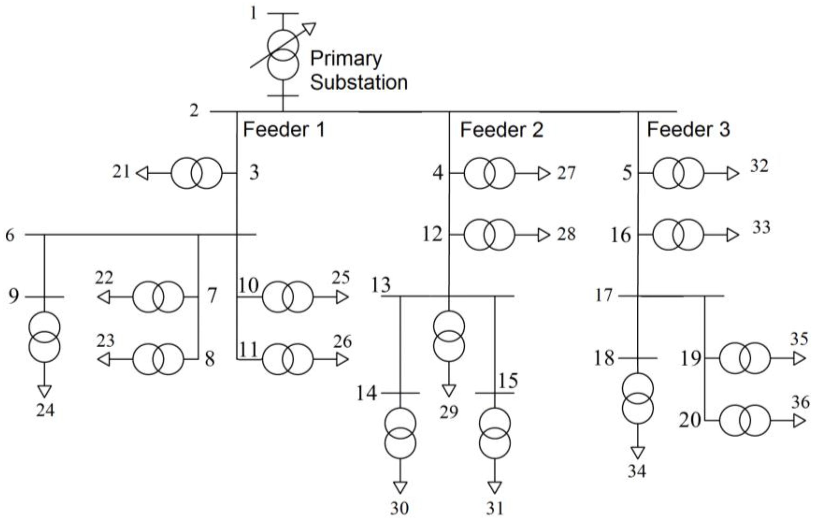
The test grid for this work was developed on the basis of analysis of existing distribution networks in the Moscow region. The fragments of the network were reduced for the compact form of representation. The resulting scheme is shown in
Figure 1.
Load of the nodes is modeled by week (7 days) profiles of active and reactive power, averaged over one-minute intervals.
Regime control in the distribution networks is aimed at providing a desirable voltage level at the connection points of consumers; at the same time, voltage levels are monitored on the low voltage side of the distribution transformers.
The local and international power quality standards (IEEE Std. 1159:1995, IEEE Std. 1346:1998, EN 50160:2010, GOST 32144:2013) define different voltage limits on supply terminals.
In the Russian local standard (GOST 32144:2013), the limit voltage overdeviation and underdeviation are equal to 10%. Voltage drop in the distribution networks does not exceed 5%. Thus, for support of the lower admissible limit of the most distant customers, the voltage on the side 0.4 kV of the distribution transformers should not be lower than 95% of the rated value. The closest customers can be directly connected to the distribution transformers; therefore, the upper voltage limit on the side 0.4 kV of distribution transformers should not be greater than 110% of the rated value.
Consequently,
- −
the upper limit is defined by the closest customers and is equal to 110% of the rated voltage;
- −
the lower limit is defined by the most distant customers and is equal to 95% of rated voltage.
The goal of the voltage regulation system is to provide a voltage level on the side 0.4 kV of distribution transformers in the range of 0.95–1.10 Un.
In spite of a broad range of admissible values, these requirements are often violated. It is typical for long-length distributive grids to have a large number of heterogeneous loads.
A traditional approach to the voltage regulation in distributive grids by means of OLTCs is based on local measurements of current and voltage at a primary substation.
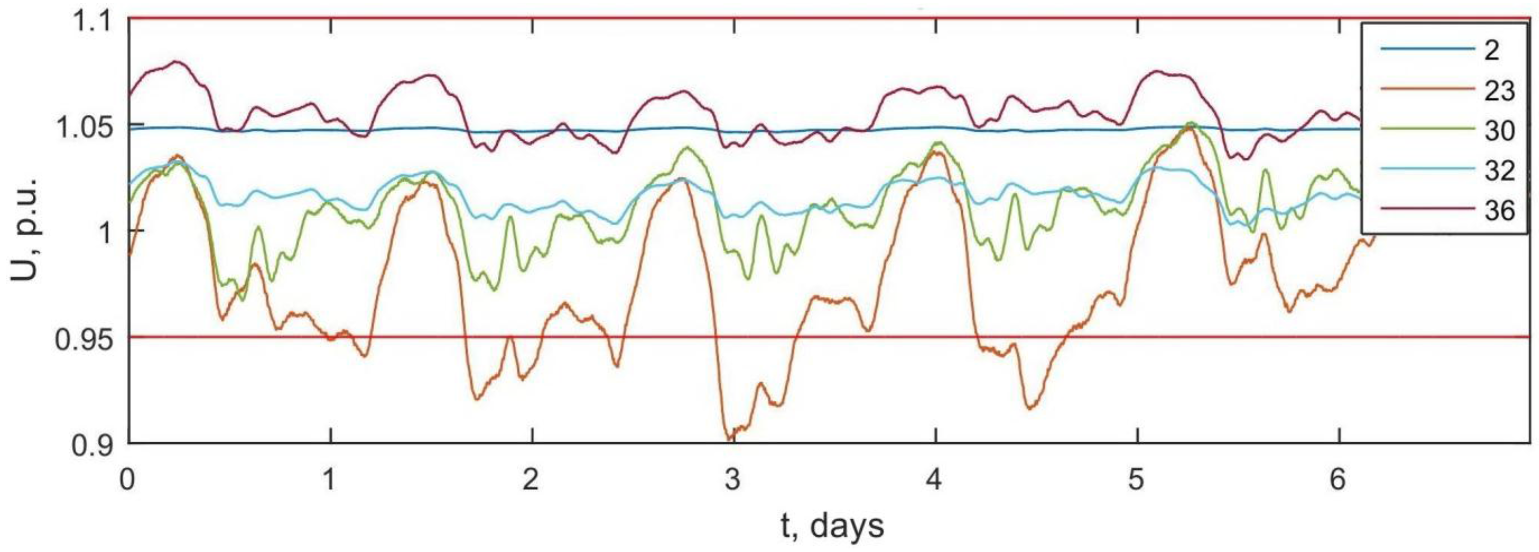
In the domestic distribution grids, the most common type of regulation is voltage stabilizing when the voltage on the low voltage side of the primary substation maintains a constant level.
Voltage diagrams of the most specific nodes of the grid in the case of voltage stabilization at the primary substation are represented in
Figure 2. These diagrams are plotted for the 0.4 kV side of distribution transformers 10/0.4 kV.
Figure 2 shows that there are number of customers with unacceptable voltage levels.
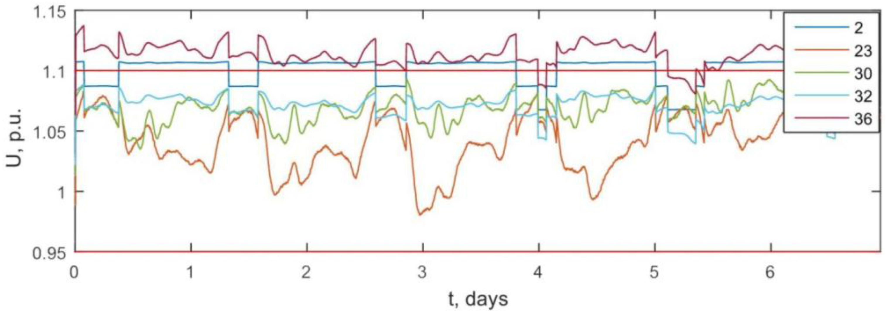
In the case of opposite regulation, the voltage level at the primary substation varies proportionally to the total current through the transformer. Application of the opposite regulation method considerably reduces the number of voltage violations in the network. Voltage diagrams in the case of opposite voltage regulation are represented in
Figure 3.
The effectiveness of opposite voltage regulation depends on the accuracy of the initial setup which includes the choice of coefficients of proportionality between the current through the transformer and the voltage level on the low voltage side of the primary substation. As a rule, the results of week measurements are not enough for the correct setup of a control system on the basis of the opposite regulation method; therefore, this method is seldom used in practice.
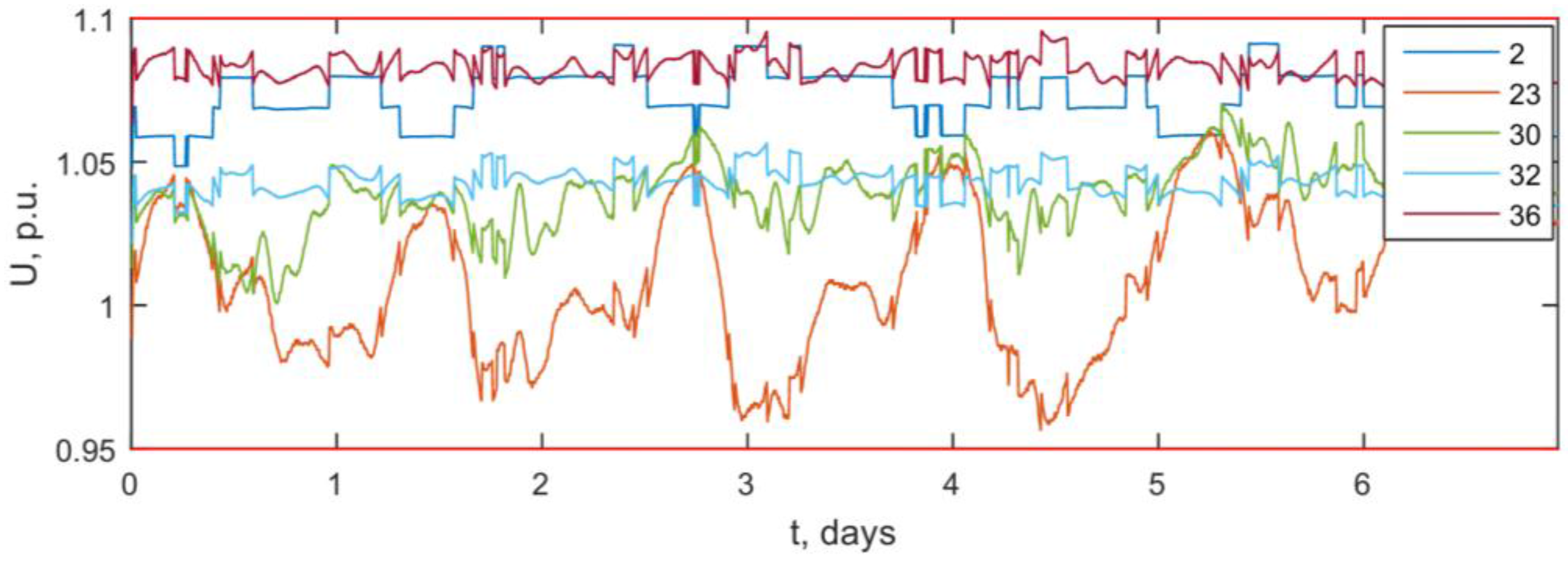
Figure 4 shows voltage profiles in the network with SSVC. In this case, voltage regulation is based on the described approach.
The information about the actual consumers’ voltage requirements makes it possible to optimize OLTC switching to meet the power demand for the maximum number of consumers.
Figure 4 shows that the voltage levels of all network nodes are within the required range.
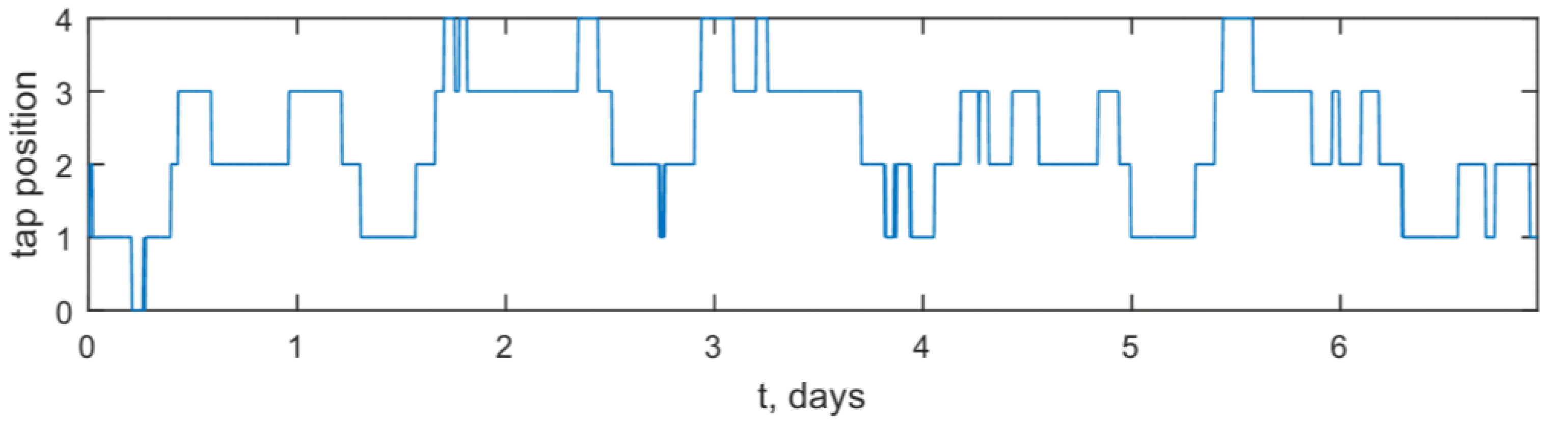
The schedule of the tap changer switching on the main substation with SSVC is shown in
Figure 5.
The graphs above show that the SSVC operates the control devices to the fullest extent. That means that equipment is used effectively.
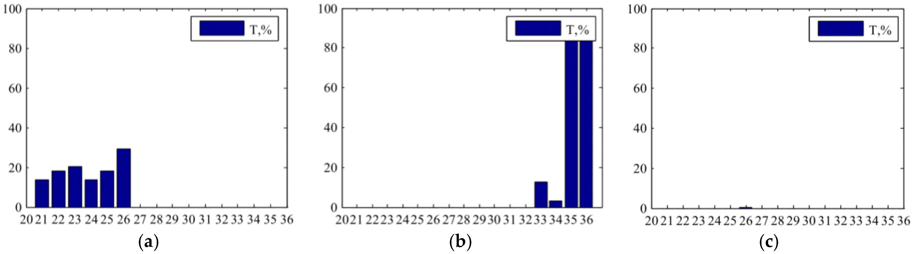
Figure 6 shows the relative time of the output voltage limit exceeded at all nodes of the range.
Configuration of the local voltage control equipment settings (no-load tap changer, booster transformer, reactive power compensator) is required in the case of the output voltage being out of range and it indicates the engineering incapability of normalizing stress in the power network.


