1. Introduction
The wireless access for vehicular environment (WAVE) is a recently developed wireless communication technology that enables the instant update of traffic information to vehicles. Vehicular communication systems can be effectively used to enhance the traffic efficiency and to reduce traffic congestion [
1,
2].
The ubiquitous intelligent system is used to develop an intelligent vehicle communication technology on the basis of the advanced WAVE wireless vehicle communication technology for improving the functionality and reducing the risk of accidents [
3].
Systems with an efficient WAVE or multiple-input multiple-output (MIMO) antenna for a ubiquitous intelligent system are found to offer increased road efficiency in the case of high traffic conditions; these systems provide alternative routes to vehicles during high traffic conditions on the basis of the obtained traffic information, as well as providing improved communication services with Internet access [
4,
5].
Further, WAVE communication systems with a high frequency range for vehicle-to-vehicle (V2V) communication and for vehicle-to-infrastructure (V2I) communication have attracted considerable attention owing to the fact that these systems are likely to achieve a high communication rate because of a wide bandwidth and low attenuation of radio propagation by the atmosphere [
6,
7].
Typically, WAVE communication systems operate in the 5.850–5.925 GHz frequency band assigned by the Federal Communication Commission (FCC) [
8]. Further, these systems adopt the advanced orthogonal frequency division multiplexing (OFDM) scheme to achieve high-speed data rates up to 6–27 Mbps. These characteristics make the WAVE communication system an attractive physical layer scheme with a high-efficiency antenna for a ubiquitous intelligent system.
These systems consist of on-board units (OBUs) placed on vehicles and road-side units (RSUs) placed on infrastructures [
9]. To maintain seamless communication among fast-moving vehicles, the antennas usually exhibit an elliptical beam pattern in the vertical cross-section of the azimuth. In cases where the antennas do not exhibit an elliptical beam pattern, the accessible distance for vehicular communication will be reduced owing to unnecessary radiations. Therefore, it is important for the OBU antennas to exhibit an elliptical beam pattern with a suitable bandwidth.
Numerous studies have been conducted on antennas for WAVE communication systems. Most of these studies have only considered the frequency band and the omnidirectional beam pattern of OBU WAVE antennas. These OBU antennas exhibit an omnidirectional beam pattern suited to a WAVE communication system.
Printed antennas were described with an omnidirectional beam pattern [
10]. Further, other research showed the pattern characteristics of the printed antennas using a micro-strip patch and an etched-upon microwave substrate layer; from the results of their study, it was found that the printed antennas exhibit an appropriate omnidirectional beam pattern suited to global positioning system (GPS) satellite receiving systems [
11]. However, it should be noted that printed antennas are not the most suitable antennas for our purpose, which require V2V/V2I (V2X) communication.
We proposed the rectangle array patch antennas structure to increase the performance of the antenna by reducing the return loss and the side-lobs waves of unnecessary radiation.
2. Antenna Design
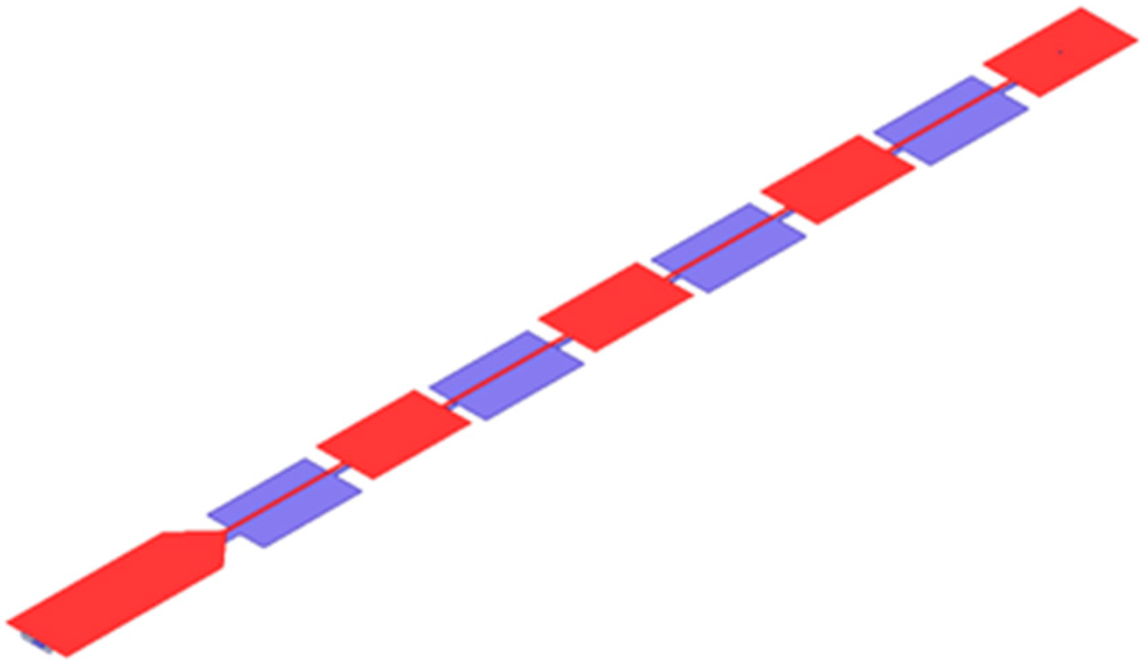
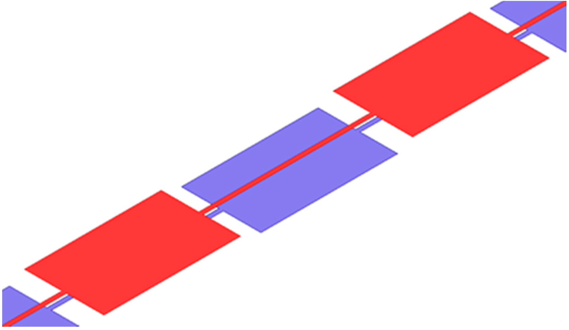
It is critical for vehicular antennas for WAVE communication systems to exhibit a high gain over the field of view (FOV) of the beam pattern, with a low return loss. To satisfy these two main objectives, we designed an array antenna structure, as shown in
Figure 1. This structure consists of four small rectangular segments that are used to generate the required resonant frequency.
Figure 1.
Proposed antenna structure.
To achieve high efficiency and to ensure the radiation of an elliptical beam pattern, an array structure with four elements, with an area of 15.5 × 8.5 mm
2 per rectangular patch, is used in the ground plane and the feed plane, as shown in
Figure 2.
Figure 2.
Structure of the proposed antenna model with a ground layer and a feed layer.
Table 1 lists the characteristics of the WAVE antenna structure that are determined experimentally to obtain an optimal beam pattern while maintaining the resonant frequency.
Table 1.
Characteristics of the proposed wireless access for vehicular environment antenna structure.
| Characteristic | Parameter |
|---|
| Base Material | Teflon |
| Permittivity [ ε ] | 2.2 |
| Thickness | 0.8 mm |
| Width | 9.6 mm |
| Length | 169 mm |
3. Results and Analysis
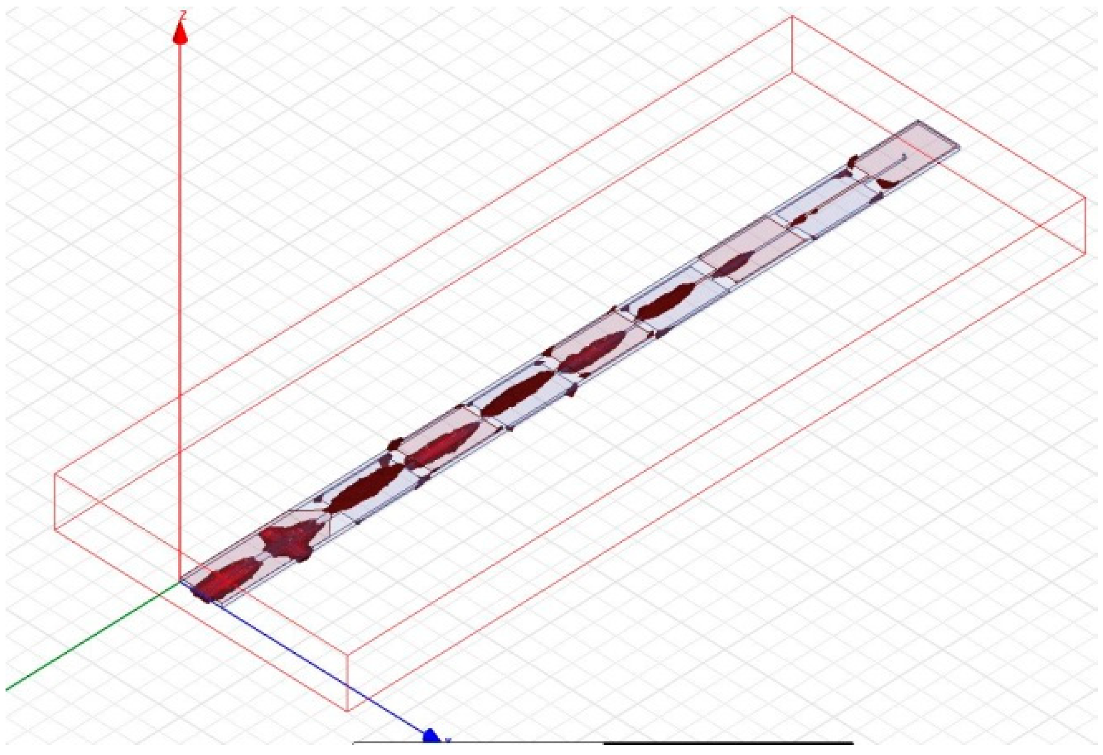
In this study, an orthogonally configured array antenna has been simulated on the roof of a vehicle. To achieve high polarization efficiency, the E and H plane pattern performance of the proposed antenna must track in both amplitude and phase over the required FOV. The cross-polarized response shows that the polarization efficiency is inversely proportional to the unwanted energy. The simulation results are calculated using the High Frequency Structure Simulator (HFSS).
Figure 3 shows the simulated near-field radiation of the proposed WAVE antenna.
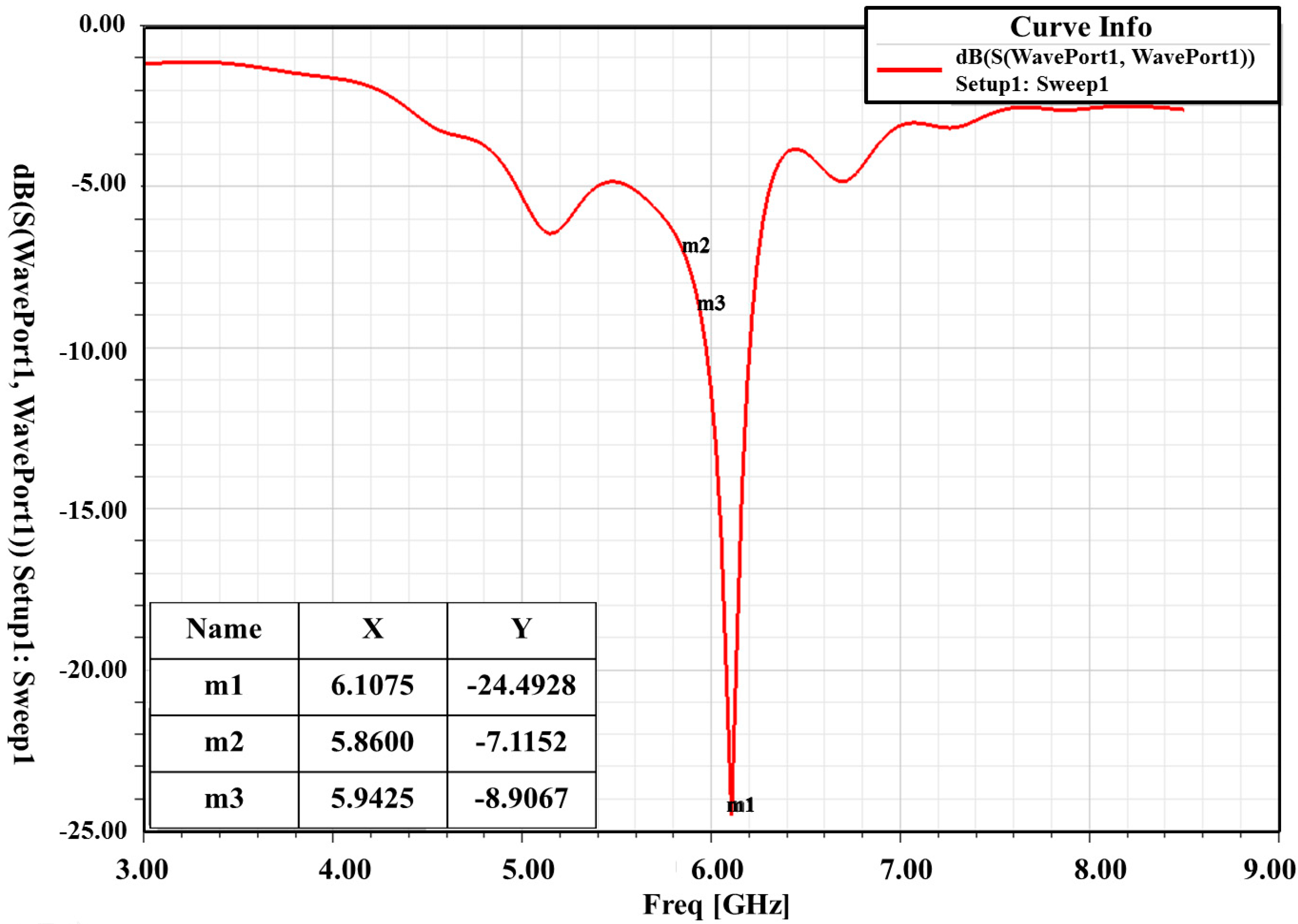
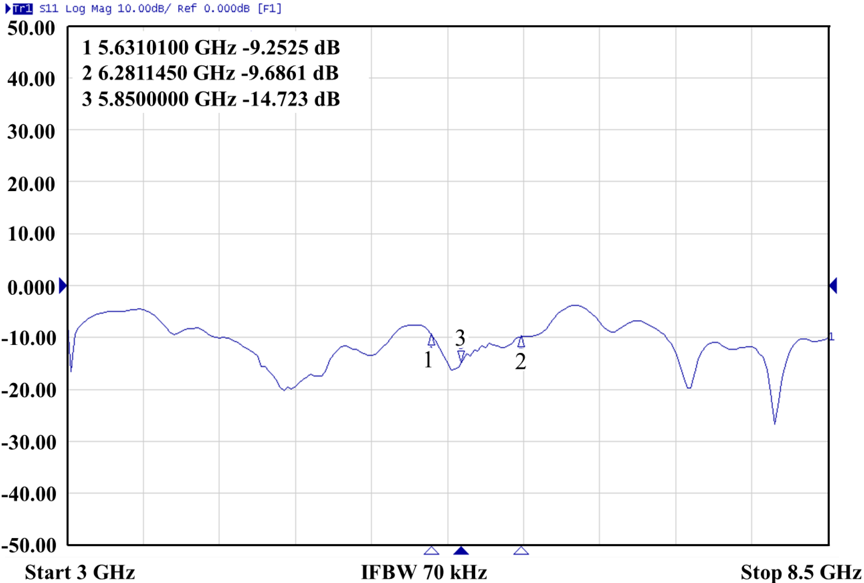
The FOV requirements differ for WAVE communication systems. Further, it is essential for the return loss of the WAVE communication systems to exhibit a minimum value of −24.47 dB over the FOV. The FOV for WAVE communication systems is elevated at an angle of 15° above the edge to center. However, only an omnidirectional FOV is required by consumers.
Figure 4 shows the simulated return loss of the proposed WAVE antenna. The simulation results show that the proposed array antenna model improves the return loss from −24.47 dB to −19.70 dB.
Figure 3.
Simulation result of near-field radiation.
Figure 4.
Simulation result of return loss.
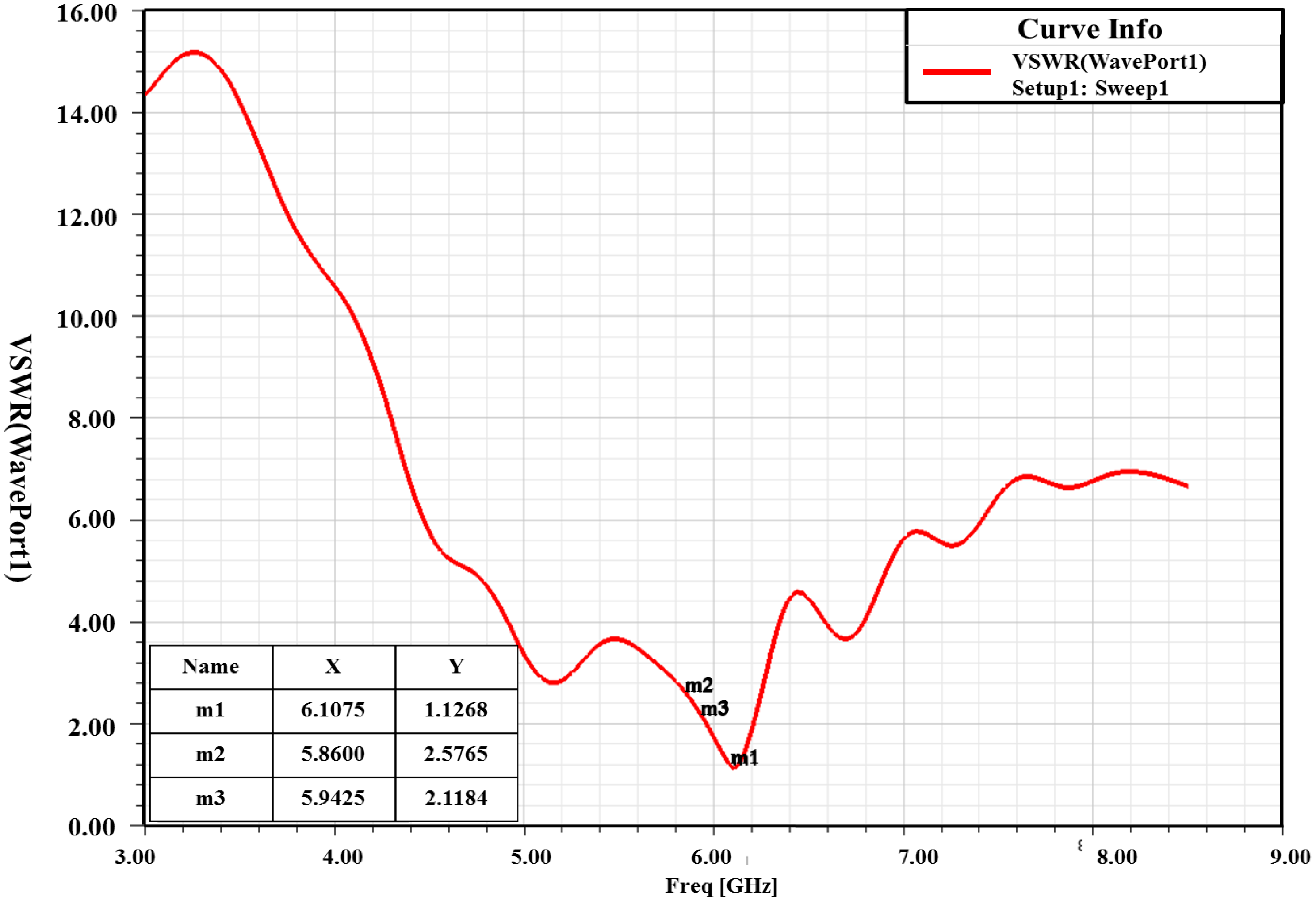
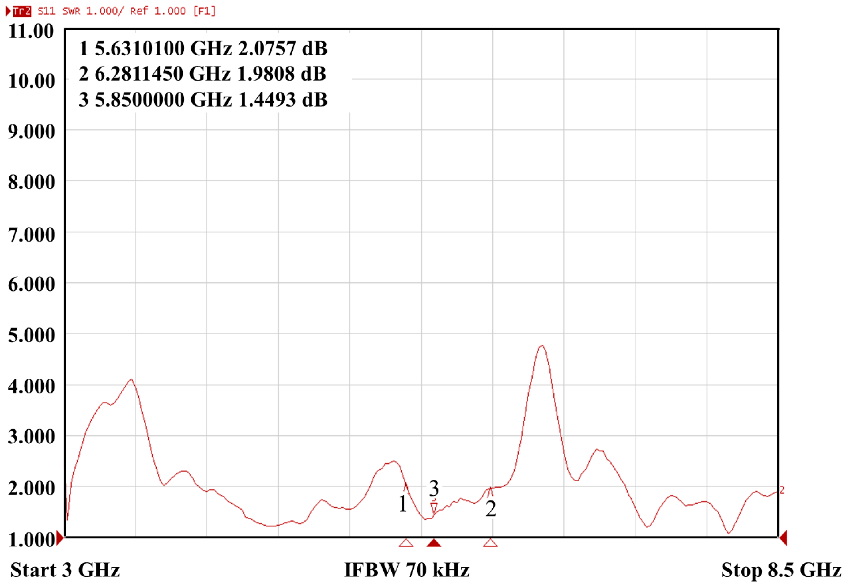
Figure 5 shows the simulation result for the voltage standing wave ratio (VSWR) for WAVE communication systems. As shown in this figure, the array antenna model exhibits a sufficient VSWR of 1.18 for the WAVE bandwidth.
Figure 5.
Simulation result of voltage standing wave ratio (VSWR).
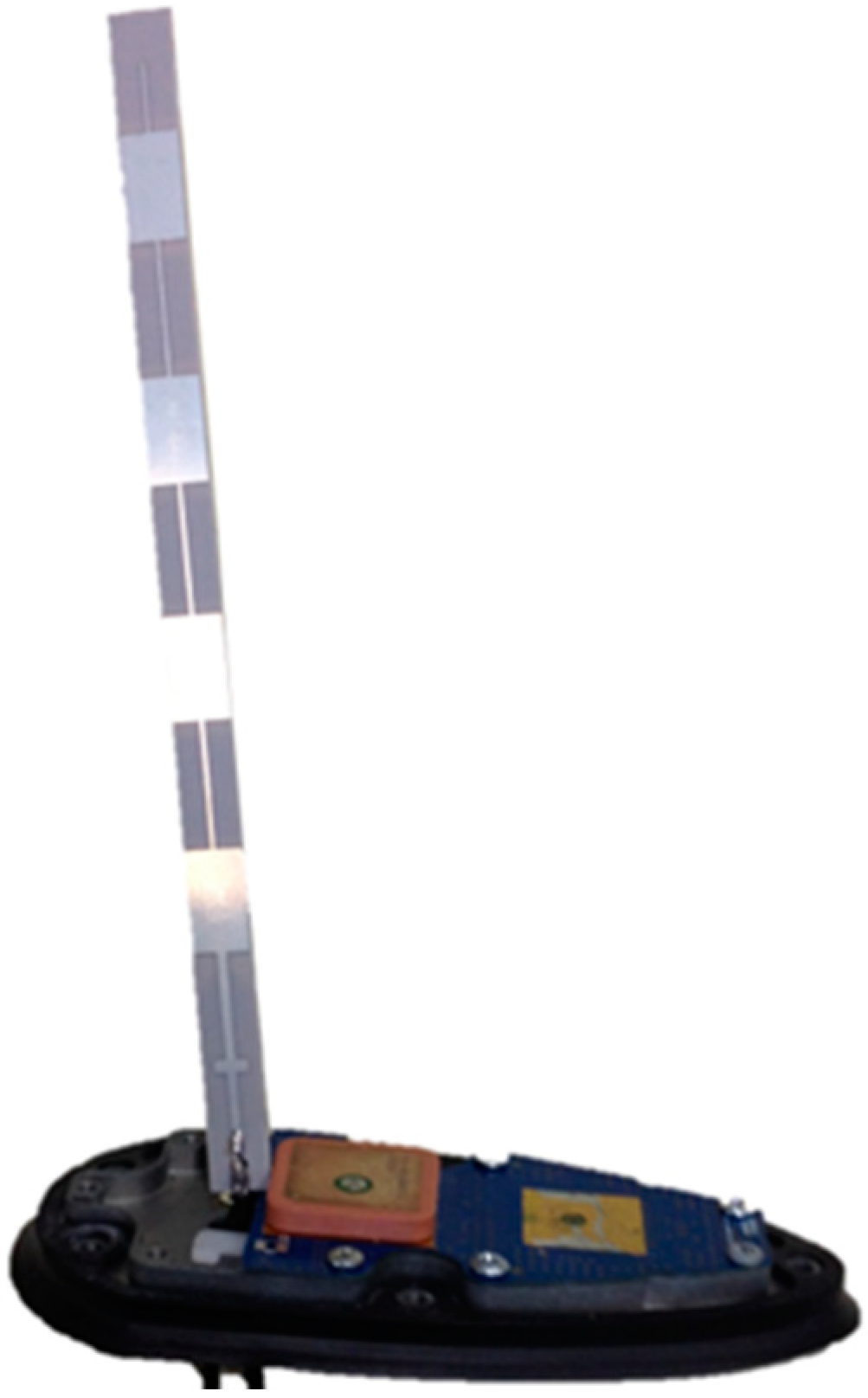
Figure 6 shows the proposed vehicular WAVE antenna. This antenna comprises a WAVE band patch antenna, microwave printed circuit substrates, discrete RF components, a ceramic patch for the GPS satellite, and digital audio broadcasting (DAB).
Figure 6.
Proposed vehicular antennas model with GPS and DAB.
From the results of the measurement, it can be inferred that in most cases, the simulated results are not in good agreement with the results obtained with the vehicular antenna, despite the fact that the same vehicular antenna meets the same specifications on a ground plane in an anechoic chamber. During a special test drive, the performance of the proposed antenna has been evaluated by placing the antenna on different points on the roof of a vehicle.
Figure 7 shows the measured return loss of the proposed WAVE antenna.
Figure 7.
Measurement result of return loss.
From the results of the measurement, it is found that the array antenna model has a VSWR of 1.44 for the WAVE bandwidth, as shown in
Figure 8.
Figure 8.
Measurement result of VSWR.
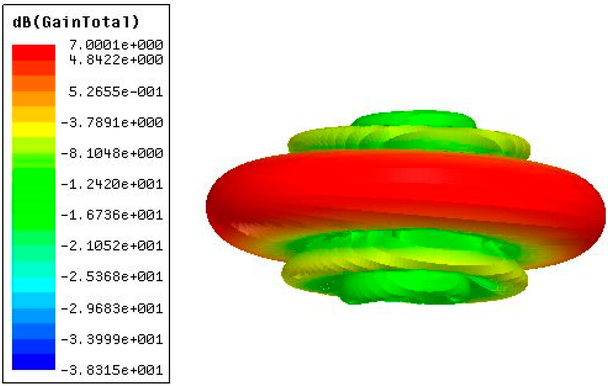
Figure 9 and
Figure 10 show the radiation beam patterns of the antenna vertically located on the roof of a vehicle. The proposed array antenna exhibits a gain of up to 3 dB over the FOV, as compared with a shark fin type omnidirectional antenna model.
From the results of the simulation and measurement of the implemented prototype models, the radiation pattern of the WAVE array patch antenna is analyzed for an actual vehicle. The far-field radiation pattern of the proposed antenna was analyzed in two different ways to compare the results of the ground test with those of the anechoic chamber test.
Figure 9.
Simulation result showing the top view of the radiation beam pattern.
Figure 10.
Simulation result showing the side view of the radiation beam pattern.
The analytical solution of the array in space shows a gain of 7 dBi for the radiation component. This reference value is used to analyze the following high-frequency structure simulation systems.
The results of the measurement analysis show that the surface current is distributed on the metallic parts of the vehicle body. The intensity of this current is expressed in terms of the azimuth and elevation angles.
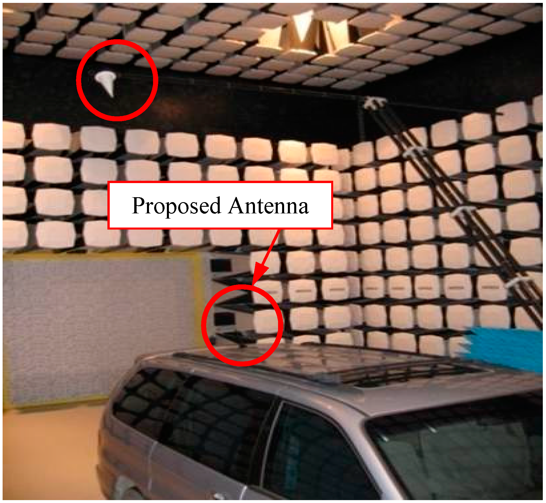
Figure 11 shows the excited antenna measurement equipment in the backlight of the vehicle.
The radiation beam pattern attributed to an elevated FOV varies only slightly, and the radiation power density is high for a low value of radiation power and azimuth radiation. Further, the radiation power concentrates near the edges and gaps in a large FOV.
The proposed array antenna is mounted on the roof of a vehicle. High-frequency structure measurement system was analyzed around the vicinity of the patch antenna and the near-field components were determined. The geometry of the vehicle body and the excitation of the array antenna on the roof were combined for the high-frequency measurements. The measurement of the far-field radiation pattern of the proposed antenna takes about few hours in an anechoic chamber. The results of this measurement must be validated with those obtained using the antenna measurement equipment at Korea Automotive Technology Institute (KATECH), Cheonan-si, Korea.
Figure 11 shows the electromagnetic anechoic chamber in KATECH.
Figure 11.
Anechoic chamber in KATECH for antenna measurements.
The maximum communication range for the intelligent transportation systems (ITS) operation is determined on the basis of the spacing between roadside beacons [
12]. A spacing of 1 km implies a maximum operating range of 500 m to the nearest beacon; A link budget with 10 dB margin over 500 m range. If a high gain antenna with an elliptical directivity of 7 dBi was used for the vehicular antenna, to possibly enhance coverage, then the beacon antenna would require a directivity > 40 dBi.
The antenna must also enable communication with nearby vehicles, by possibly forming a local area network for the transfer of data. This requirement for all-round coverage, which is free of radiation pattern nulls, conflicts with the requirement for a focused beam communicating with the access beacon. The antenna pattern must also be shaped such that the antenna gain is adjusted on the basis of the distance between the vehicle and the beacon. It is important to validate the abovementioned results against the results of the ground test. The high speed proving ground for the WAVE communication test is shown in
Figure 12.
Figure 12.
Proving ground for vehicle-to-vehicle and vehicle-to-infrastructure (V2X) communication measurement with the proposed antenna.

