
Research on the Tensile Mechanical Properties of a Braided Corrugated Hose and Its Axial Stiffness Model

School of Mechanical Engineering, Southeast University, Nanjing 211189, China
*
Author to whom correspondence should be addressed.
J. Mar. Sci. Eng. 2021, 9(9), 1029; https://doi.org/10.3390/jmse9091029
Submission received: 15 August 2021
/
Revised: 13 September 2021
/
Accepted: 14 September 2021
/
Published: 18 September 2021
(This article belongs to the Section Ocean Engineering)
Abstract
:Braided corrugated hoses are widely used in displacement compensation and vibration absorption environments due to their excellent flexibility and energy dissipation properties; however, the axial stiffness has rarely been discussed before as an important physical property of braided corrugated hoses. In this paper, the theoretical axial stiffness model for braided corrugated hoses is established based on the energy method and the theory of the curved beam. The influences of the braiding parameters of the metallic braided tube and the structural parameters of the bellows on the axial stiffness are also discussed. Through finite element tensile testing, the axial stiffness curves of the braided corrugated hose under different braiding angles and different wire diameters are obtained. The theoretical axial stiffness model is in good agreement with the simulation experiment, which reflects the nonlinear effects of the braiding angle and wire diameter on the braided corrugated hose. This paper provides an accurate method and basis for the design of braided corrugated hoses in the future.
1. Introduction
Braided corrugated hoses are important connection components in pressure vessels and pipeline systems, providing compensation displacement, vibration absorption, and noise reduction. They are widely used in petrochemical, aerospace, automotive, marine, and other fields [1,2]. The performance of a braided corrugated hose directly affects the normal work of the pipeline system and is vital to its reliability.
A braided corrugated hose is composed of metal bellows and a metallic braided tube. Over the years, there have been many studies on the axial mechanical properties of metal bellows. Anderson [3] used the simple beam approximation method to obtain the displacement and stress solutions for U-shaped bellows by decomposing the asymptotic integral, then further derived the approximate formulae on this basis. Based on the theory of having a thin annular shell, Qian [4] calculated the stress and strain for C-shaped bellows under internal pressure and axial force with the given calculation formula, which can be used in engineering design. They also obtained an accurate linear analytical solution for U-shaped bellows based on the exact solution of the annular shell. Huang [5] obtained the numerical solution for C-shaped bellows using the initial numerical integration parameters and improved the calculation accuracy for the stress and deformation under axial force and uniform distribution pressure using an extrapolation formula. Laupa [6] used the energy method to analyze the mechanical properties of the U-shaped bellows under axial load and external force and obtained the load–displacement and load–stress expressions.
Many researchers have also used the finite element method to analyze the mechanical properties of bellows. Chen [7] established the finite element analysis model for U-shaped bellows. The results of the analysis using the finite element analysis showed that this method can simulate the load–stress response of U-shaped bellows well. Yang [8] carried out a finite element analysis on multilayer bellows and found that this method can better simulate the characteristics of multi-layer bellows by comparing the results with the experimental values. Zhu [9] established a finite element model of multi-layer U-shaped bellows with sandwich damping. The simulation results were compared with the EJMA formula to verify the rationality of the model. Zhou [10] used ABAQUS to establish an axisymmetric finite element model of the bellows with different numbers of layers and simulated the axial stiffness and stress–strain distribution of the multi-layer U-shaped bellows. The results showed that the stiffness of the bellows decreased significantly with the increase in the number of layers at constant thickness, while the overall stiffness of the bellows changed significantly under large deformation, which was divided into elastic and plastic stiffness.
Regarding braided tubes, many researchers have tried to investigate the structural and mechanical properties. Brunnschweiler [11] first derived the structural parameters of the diamond-shaped woven mesh and described the practical method used to derive the mechanical properties. Hristov [12] investigated the mechanical behavior of a woven mesh sleeve without an inner core under axial tension. A predictive model of the mechanical response of the braids based on the constituent yarn characteristics and machine parameters was also developed. Phoenix [13] established a response for a braided tube with an elastic inner core and found that the braiding angle, crimp angle, modulus of the inner core, and Poisson’s ratio all affect the mechanical properties of the entire braided tube.
Many researchers have used the energy method to analyze the mechanical properties of braided tubes. Grosberg [14] first established the energy equation for a plain weave fabric, which was found to be a good description of the mechanical properties of woven meshes via experimentation. Hearle [15] studied the basic theory of the energy method and discussed the elastic responses of plain weave fabrics. Dabiryan [16] used the energy method to analyze the mechanical properties of the diamond braid, deduced the equivalent elastic moduli of the different stages, and verified the reliability of the model through experiments.
Overall, the mechanical properties of metal bellows and braids have been widely researched separately, although the mechanical properties of braided corrugated hoses have rarely been studied. The axial stiffness and tensile properties of braided corrugated hoses are very important in determining their service range and life; therefore, in this paper we adopt a method involving curved beam element analysis to establish an axial stiffness model for the metal bellows, while for the metallic braided tube, the energy method is used to establish the axial stiffness model. For the nonlinear phenomenon of the metallic braided tube, the Taylor series expansion is used to fit the axial stiffness. Finally, the axial stiffness model of the metal hose is established by combining the two models. The accuracy of the model is verified through experiments.
2. Mathematic Model of Braided Corrugated Hose
2.1. The Structure of the Metallic Braided Tube
The structure of the metallic braided tube is shown in Figure 1. The braided corrugated hose is made up of an external metallic braided tube and internal metal bellows. The metallic braided tube is made up of two sets of metal fibers, which are interwoven in opposite directions, with the model geometry parameters shown in Figure 1b. The key geometrical parameters are the diameter of the metal wire (d), the inner diameter of the metal braided tube (D) (also the outer diameter of the bellows), the equivalent diameter of the metallic braided tube (), and the braiding angle (α). The diamond trellis structure (ABCD) shown in Figure 2 can be obtained by unrolling the braided tube along the axial direction. AC is the axis direction of the braided tube and x is the spacing of the one plait. When the braided tube is stretched or compressed, x increases or decreases, respectively, while the braiding angle decreases or increases accordingly. The braiding angle can be defined by the pitch or the length of one side of the diamond trellis (q).
where N is the number of filaments.
The spacing of one plait x can be defined as:
In Figure 2, p is the projection of the strand length normal to the direction of crossing strands, while θ is the angle between p and q. Figure 3 shows a projection of section EE’ of the braid normal to the plane. The crimp of the braid thread will be defined as the difference in length between the actual length of the thread in diamond trellis unit (BC) and the length of its projection on the plane (B′C). The crimp c can be defined as:
The crimp angle of the yarns in the braid structure can be given by:
BB′ is approximately equal to the yarn diameter (d) and B′C is approximately equal to the straight line, hence:
2.2. The Mechanical Properties of Wires under Tensile Load
We assume that the metallic braided tube is subjected to an axial force, . As shown in Figure 4, the load acting on each wire can be expressed as:
where n is number of wires in the braid structure and is in the direction of the braid axis.
To analyze the mechanical behavior of metallic braided tube, the unit cell of the 1/1 pattern is considered, as Figure 5 shows. The wires are assumed to have the following properties:
- (1)
- Assuming that the wire has a circular cross-section, the diameter and cross-section of the wire are unaffected by the applied load;
- (2)
- The wire elongation is based on Hooke’s law, , where σ is the stress in the wire, E is the modulus of elasticity of the wire, and ε is the strain in the wire;
- (3)
- The bending of the filament is based on the theory , where M is the moment, κ is the yarn curvature, and .
In its normal state, the wire is woven in a spiral around the axis. According to Brunnschweiler’s theory [17], the wire in the unit cell is an arc, the length of which can be obtained by elliptic integrals, which makes the calculation considerably more difficult. To simplify the calculation, the length in the unit cell is simplified to the length of the line BC, as Figure 3 shows. It is assumed that the internal force and the contact force of the wires are ignored and the strain energy is mainly generated under the action of the external force . The strain energy of the unit cell can be expressed as:
where is the total strain energy of the unit cell, is the extension energy of the unit cell, and is the bending energy of the unit cell.
Since the deformation of the wire is elastic, the tensile strain energy and the bending strain energy can be calculated using the following formula.
where T is the tension force of the unit cell, q is the length of the wire in the unit cell, E is the Young’s modulus of the wire, and I is the cross-sectional moment of inertia.
where f is the force along the wire plane (COB).
As such, the strain energy for the AB’ part can be derived as follows:
where and , while d is the diameter of the wire.
The total strain energy of the unit cell is as follows:
For the unit cell, the external force and the force in the unit cell are shown in Figure 4 and the relationship between them can be expressed as follows:
For the metallic braided tube, the relationship between the total tensile force and the tensile force on the unit cell is:
where n is the total wires in the metallic braided tube and is the wire packing factor, defined as the ratio of the fiber volume to the yarn volume. According to the study by Hachemi [18], this can be expressed as:
According to the principle of the virtual work, the work done by the unit cell under axial load should be equal to the total internal strain energy. The work done by the unit cell and the total internal energy can be expressed as below:
where is the axial deformation of the unit cell.
The force–deformation relationship for the entire metallic braided tube can be obtained by putting the into .
The axial stiffness of the entire metallic braided tube can then be expressed as:
When the metallic braided tube is subjected to the axial load, the volume of the metallic braided tube changes with axial elongation and the metal wires rub and contact each other, meaning the axial stiffness of the metallic braided tube presents nonlinear characteristics. According to the theories of previous scholars [19,20,21], the axial stiffness of the metallic braided tube can be expanded by repeating the Taylor series three times, as shown below:
By adding the correction coefficients , , and , the nonlinear equation of the metallic braided tube under axial loading can be obtained as follows:
The correction coefficients , , and can be obtained from the experiment results.
2.3. The Stiffness of the Bellows
The structure of the bellows is shown in Figure 6. Here, D is the out diameter, is the inner diameter, is the radius of the crest, is the radius of the trough, w is the pitch of convolution, and t is the thickness of the bellows. As the bellows have a periodic structure, it is sufficient to consider only half waves in the study of their deformation law. The wave height of the bellows and the radius of the circular shell section are very small, so the curved beam with a width of one is intercepted along the circumference [22], which is subjected to external forces and each internal force component, as shown in Figure 7.
We assume that point H is supported and point K can move along the direction of the force but cannot rotate. Relative to point K, the rotation and the vertical displacement of point J are shown in Equations (26) and (27), respectively:
where E is the modulus of elasticity and J is the moment of inertia.
Relative to point H, the rotation angle of point K and the vertical displacement are as follows:
According to the principle of deformation coordination, the and can be expressed as:
The axial deformation of a single wave can be obtained by:
By subbing Equations (27), (29) and (30) into Equation (31), the single-wave stiffness formula of the bellows can be obtained as follows:
As such, the stiffness of the bellows for m waves is:
When and the wave height , Equation (33) can be written as:
where , while the relationship between force and deformation can be expressed as follows:
2.4. The Axial Stiffness of the Braided Corrugated Hose
The braided corrugated hose is made of a metallic braided tube and metal bellows arranged in parallel. The stiffness of the braided corrugated hose can be superimposed from the stiffness of the metallic braided tube and the metal bellows. The relationship between the axial force and the deformation can be expressed by the following equation:
3. Numerical Experiment with the Braided Corrugated Hose
3.1. The Material and Structure of the Braided Corrugated Hose
The braided corrugated hose used in the numerical simulation is shown in Figure 8, while the material used for the bellows and the metallic braided tube was 304 stainless steel. The wires in the metallic braided tube underwent a cold-drawing treatment, while the physical properties of the 304 stainless steels are shown in Table 1. The structural parameters of the metallic braided tube and the bellows are shown in Table 2 and Table 3, respectively. In order to explore the effects of the braiding angle and wire diameter on the axial stiffness of the braided corrugated hose, three different braiding angles and two different wire diameters of the braided corrugated hose model were assessed in this experiment.
3.2. Simulation Setup
The bellows model was meshed as the shell element (SHELL 181) and the braid model was meshed as the beam element (BEAM 188). The meshed model is shown in Figure 9, containing 110,564 nodes and 104,164 elements. The contact between the bellows and the metallic braided tube was frictional with a coefficient 0.2. The right side of the braided corrugated hose was constrained in six degrees of freedom and fixed. The left side was constrained in five degrees of freedom and could move along the axis, as shown in Figure 10.
3.3. Numerical Results and Analysis
It can be seen from Figure 11 that the stretching deformation of the braided corrugated hose occurs in three stages. The first stage is linear stage, involving very little displacement. At the beginning of the stretching period, the metallic braided tube undergoes slight axial deformation. The axial stiffness of the braided corrugated hose is mainly provided by the metal bellows. The second stage is the soft characteristic stage, with the increase in the tensile force, the deformation of the metallic braided tube occurs as the geometry transition. The diamond trellis changes from slight deformation (first stage) to large deformation, whereby the braiding angle also changes. During this process, the friction between the wires and the change of the braiding angle cause nonlinear phenomena. The third stage is also a linear stage. After the second stage, the diamond trellis and braiding angle do not change with increases in the tensile force. The elongation of the metallic braided tube mainly results from elongation of the metal wires under tensile force. The third stage is determined mainly by the characteristics of the wire.
Figure 12 shows the axial stiffness values of the different braiding angles. It can be seen that the different braiding angles cause different levels of axial stiffness in the braided corrugated hose. The first stage of axial stiffness, involving different braiding angles, is almost the same. The greatest difference is in the second stage, whereby a critical braiding angle is assumed to exist between the second and third stages. When suffering under tensile force, a small braiding angle will achieve this critical braiding angle faster than a larger braiding angle and will enter the third stage earlier, meaning the axial stiffness will be larger than that with a larger braiding angle. When the diameter of the wire changes from 0.6 mm to 0.3 mm, the axial stiffness of the braided corrugated hose decreases significantly. This shows that the diameter of the wire is also an important factor affecting the nonlinear phenomenon.
4. Model Validation
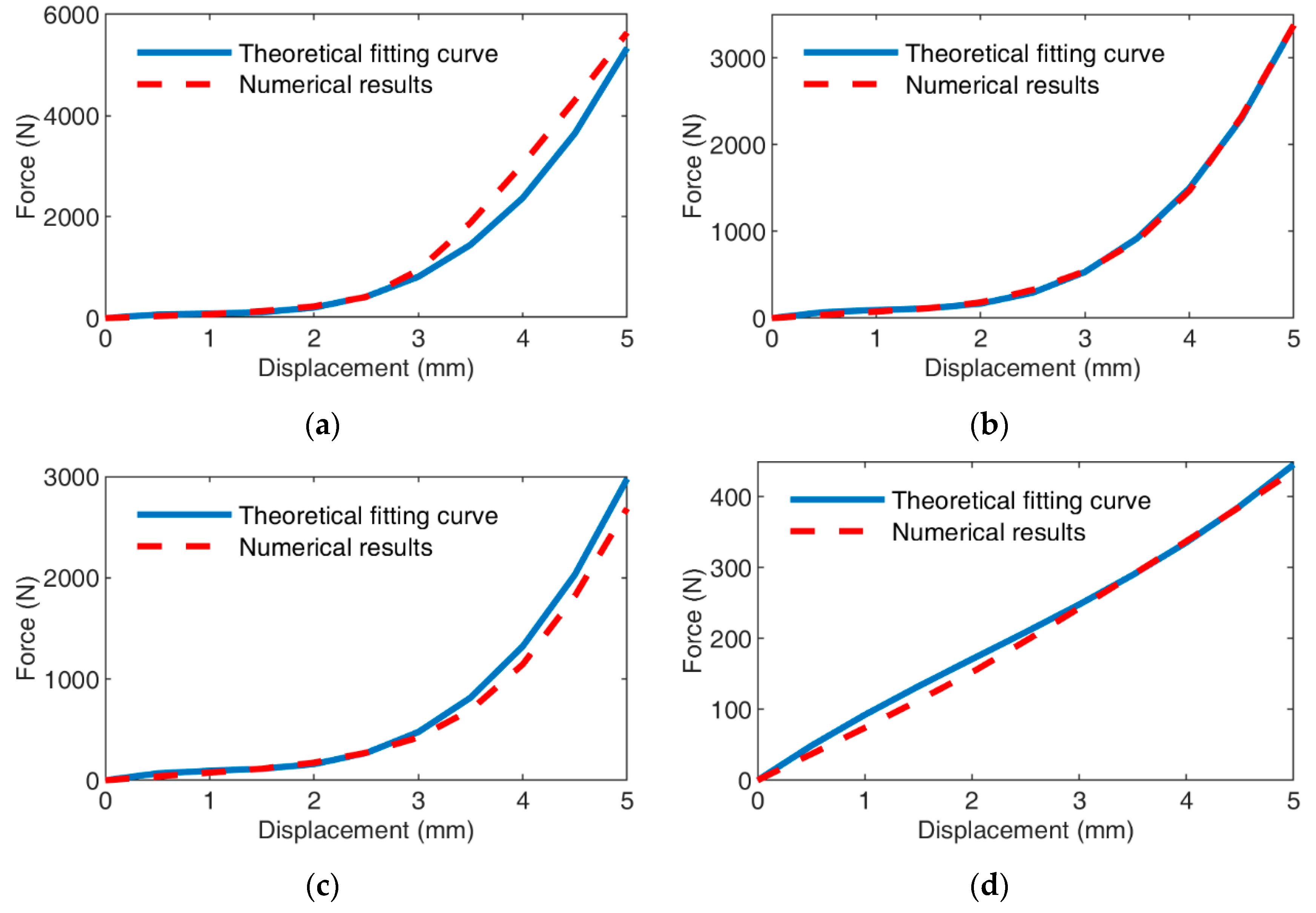
In order to verify the correctness of the axial stiffness model for the braided corrugated hose, data from sample B were selected for identification of the model parameters (as Table 4 shows) and the coefficients of the cubic polynomial were fitted using the least squares method. The parameters obtained from the fit were used with the other sample data for comparison. A comparison of the numerical experimental values with the values calculated by the theoretical model is shown in Figure 13.
With braiding angles of , , and , the theoretical fitting curves matched the numerical results well. Some points did not match exactly; the maximum error occurred at the braiding angle of , which was 21.9%. The reasons for the errors were due to changes in the diameter of the metal wire when subjected to tensile load, although it was assumed that the diameter of the wire remained constant. When the diameter of the wire was 0.3 mm, the theoretical fitting curve also matched the numerical results well. Some errors were caused by not considering the radial variation of the wire.
5. Conclusions
In this paper, a nonlinear axial stiffness model of a braided corrugated hose is established based on the energy method and the curved beam model. The simulation experimental results are used to fit the established axial stiffness model of the braided corrugated hose and the fitting coefficients are determined. The theoretical fitting curve and the simulation curve show good agreement, while the established axial stiffness model can describe the nonlinear mechanical properties of the braided corrugated hose well. In addition, the established axial stiffness model of the braided corrugated hose can also reflect the influence of the braiding angle, wire diameter, and other related parameters on its nonlinear mechanical properties, thereby allowing prediction of the structural stiffness, providing a theoretical basis for the production and design of the braided corrugated hose. These results will have important significance, guiding practical applications in pipeline engineering.
Author Contributions
This study was initiated and designed by D.H. The numerical simulations, data analysis, and writing of the paper were completed by D.H., while J.Z. provided suggestions regarding the research design and writing of the paper. All authors have read and agreed to the published version of the manuscript.
Funding
This research was funded by the National Key Research and Development Plan, grant number no. 2019YFB2006402.
Institutional Review Board Statement
Not applicable.
Informed Consent Statement
Not applicable.
Data Availability Statement
The data are part of an ongoing project.
Conflicts of Interest
The authors declare that they have no potential conflict of interest with respect to the research, authorship, and publication of this article.
References
- Huang, D.; Zhang, J. Numerical Simulation and Experimental Study on Axial Stiffness and Stress Deformation of the Braided Corrugated Hose. Appl. Sci. 2021, 11, 4709. [Google Scholar] [CrossRef]
- Pierce, S.O.; Evans, J.L. Failure analysis of a metal bellows flexible hose subjected to multiple pressure cycles. Eng. Fail. Anal. 2012, 22, 11–20. [Google Scholar] [CrossRef]
- Anderson, W.F. Analysis of Stresses in Bellows. Part I. Design Criteria and Test Results. Technical Report Archive & Image Library; UNT Digital Library: Denton, TX, USA, 1964. [Google Scholar]
- Chien, W. Calculations for semi-Circular Arc Type Corrugated Tube-Application of the Theory of Slender Ring Shells. J. Tsinghua Univ. 1979, 1, 84–99. [Google Scholar]
- Chien, H. Calculation of Stresses and Deformations of Bellows by Initial parameter Method of Numerical Integation. Appl. Math. Mech. 1982, 3, 101–112. [Google Scholar] [CrossRef]
- Laupa, A.; Weil, N.A. Analysis of u-shaped expansion joints. J. Appl. Mech. Trans. ASME 1960, 29, 115–123. [Google Scholar] [CrossRef]
- Chen, Y.; Li, Y.; Gu, B. The finite element analysis to the U-shape bellows by the ANSYS program. Press. Vessel. Technol. 2000, 17, 34–36. [Google Scholar]
- Yang, Y.; Wang, X. Nonlinear finite element analysis of the multiply bellows. Press. Vessel. Technol. 2003, 20, 13–16. [Google Scholar]
- Zhu, J.; Ma, W.; Liu, Y. Finite element analysis of high-damped multilayer U-shaped bellows’ axial equivalent stiffness. Press. Vessel. Technol. 2011, 28, 28–32. [Google Scholar]
- Zhou, L.; Li, L.; Zhao, C.Y. Performance analysis of the multi U-shaped bellows based on CAE. Mater. Sci. Forum 2014, 800–801, 390–393. [Google Scholar] [CrossRef]
- Brunnschweiler, D. Braids and braiding. J. Text. Inst. Proc. 1953, 44, P666–P686. [Google Scholar] [CrossRef]
- Hristov, K.; Armstrong-Carroll, E.; Dunn, M.; Pastore, C.; Gowayed, Y. Mechanical Behavior of Circular Hybrid Braids Under Tensile Loads. Text. Res. J. 2004, 74, 20–26. [Google Scholar] [CrossRef]
- Phoenix, S.L. Mechanical Response of a Tubular Braided Cable with an Elastic Core. Text. Res. J. 1978, 48, 81–91. [Google Scholar] [CrossRef]
- Grosberg, P. The Mechanical Properties of Woven Fabrics Part II: The Bending of Woven Fabrics. Text. Res. J. 1966, 36, 205–211. [Google Scholar] [CrossRef]
- Hearle, J.W.S.; Potluri, P.; Thammandra, V.S. Modelling Fabric Mechanics. J. Text. Inst. 2001, 92, 53–69. [Google Scholar] [CrossRef]
- Dabiryan, H.; Johari, M.S. Analysis of the tensile behavior of tubular braids using energy method, part I: Theoretical analysis. J. Text. Inst. 2016, 107, 553–561. [Google Scholar] [CrossRef]
- Brunnschweiler, D. 5—The structure and tensile properties of braids. J. Text. Inst. Trans. 1954, 45, T55–T77. [Google Scholar] [CrossRef]
- Hachemi, H.; Kebir, H.; Roelandt, J.M.; Wintrebert, E. A study of the braided corrugated hoses: Behavior and life estimation. Mater. Des. 2011, 32, 1957–1966. [Google Scholar] [CrossRef]
- Fu, H.; Hua, Z.; Zou, L.; Wang, Y.; Ye, J. Combined stiffness characteristic of metal rubber material under vibration loads. Proc. Inst. Mech. Eng. Part C J. Mech. Eng. Sci. 2019, 233, 6076–6088. [Google Scholar] [CrossRef]
- Yu, H.; Xu, Y.; Liu, W. The comparison of common static stiffness theory model of metal rubber. Gongneng Cailiao/J. Funct. Mater. 2017, 48, 11141–11146. [Google Scholar] [CrossRef]
- Zou, G.P.; Liu, Z.; Chang, Z.L.; Li, Y.L. Constitutive relation of metal-net rubber. Hangkong Dongli Xuebao/J. Aerosp. Power 2016, 31, 2318–2324. [Google Scholar] [CrossRef]
- Gao, X.; Chen, Q.; Teng, H.D. Stiffness estimation of corrugated-pipe elements for vibration isolator design. Zhendong Gongcheng Xuebao/J. Vib. Eng. 2011, 24, 280–286. [Google Scholar]
Figure 1.
Parametric model of the braided corrugated hose: (a) top view; (b) side view.
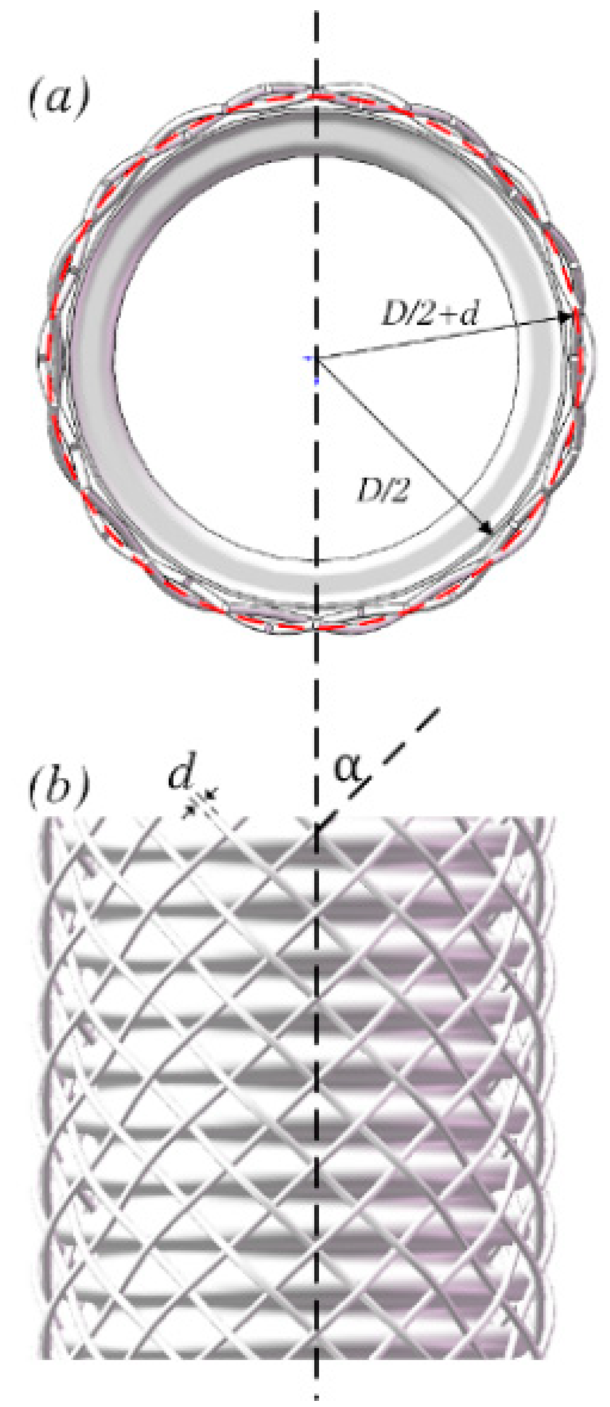
Figure 2.
Diamond trellis.
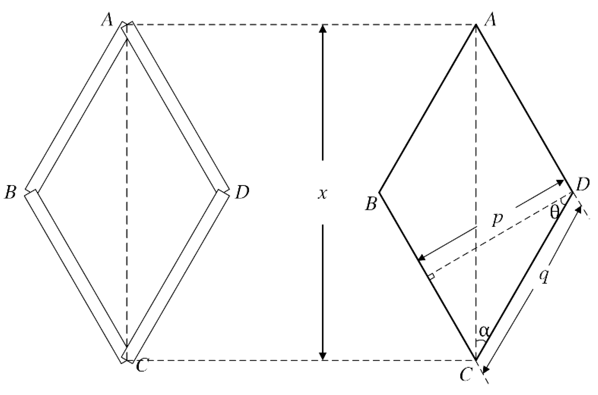
Figure 3.
Cross-section of EE’.
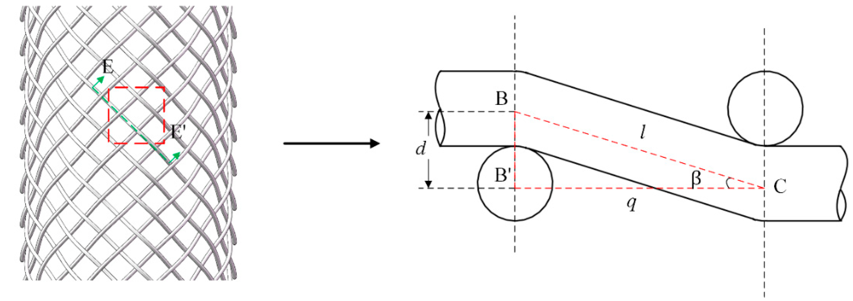
Figure 4.
Tubular braid under axial load.
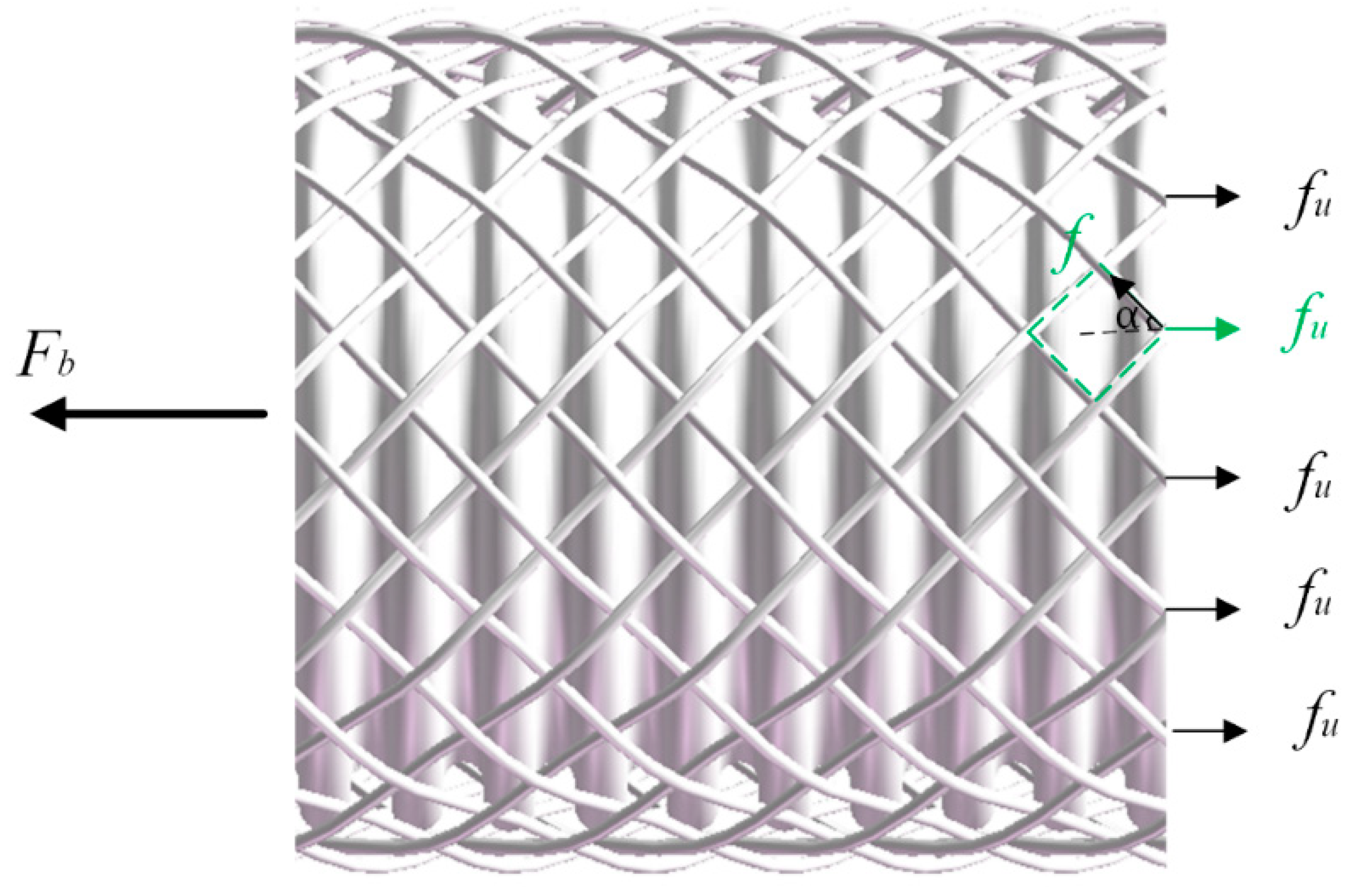
Figure 5.
Diagram of the unit cell.
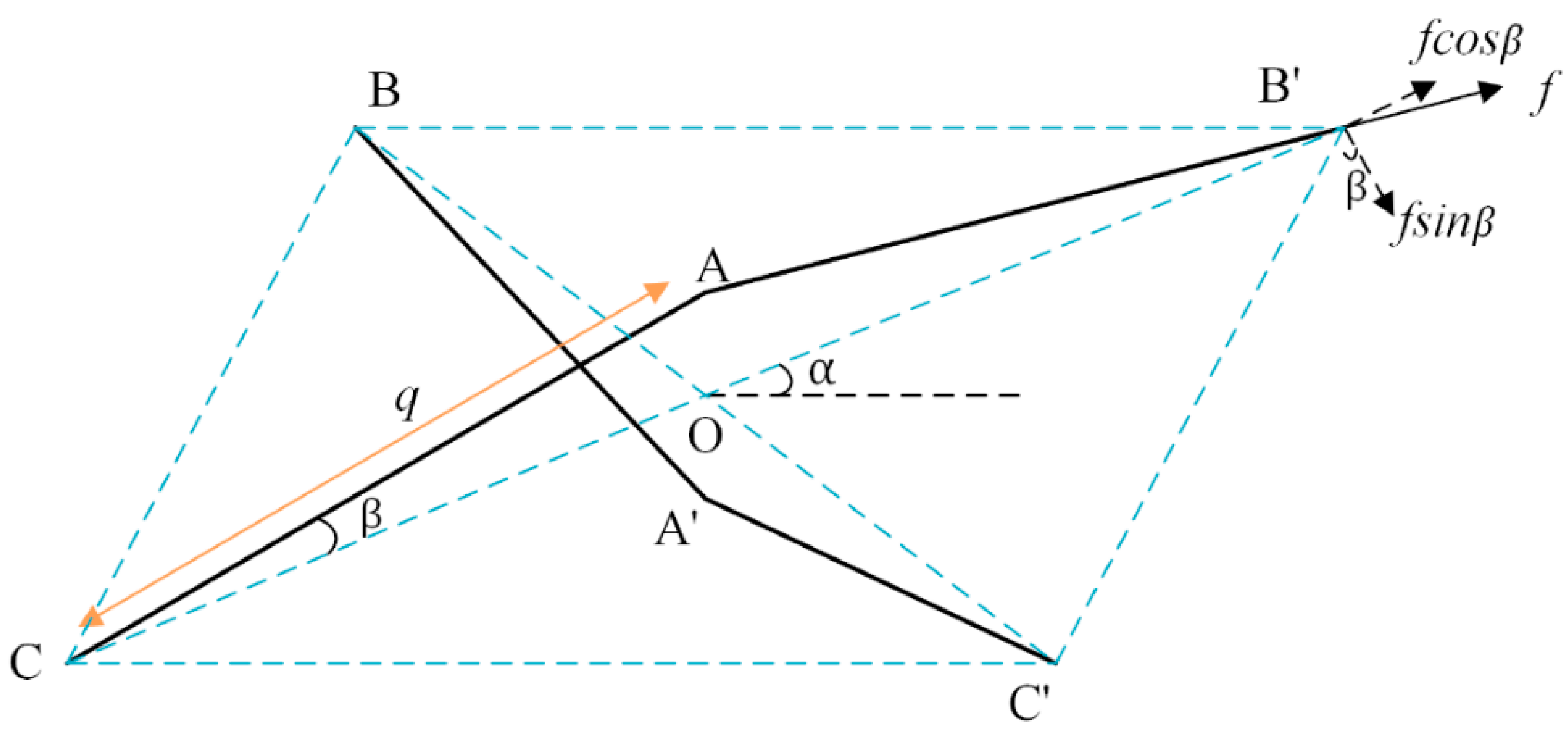
Figure 6.
The longitudinal section of the U-shaped bellows.

Figure 7.
Force diagram of the half wave.
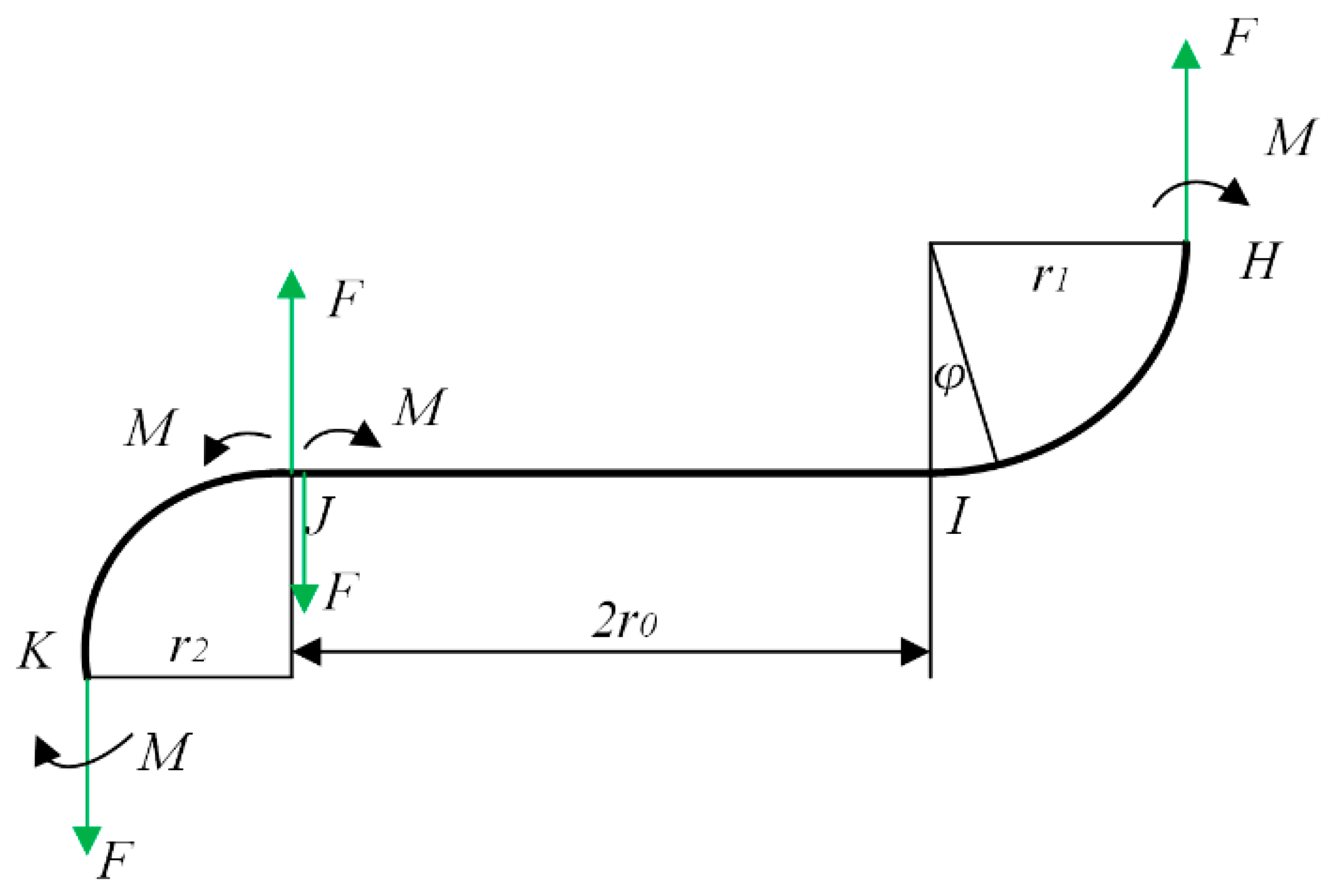
Figure 8.
The geometry of the braided corrugated hose.
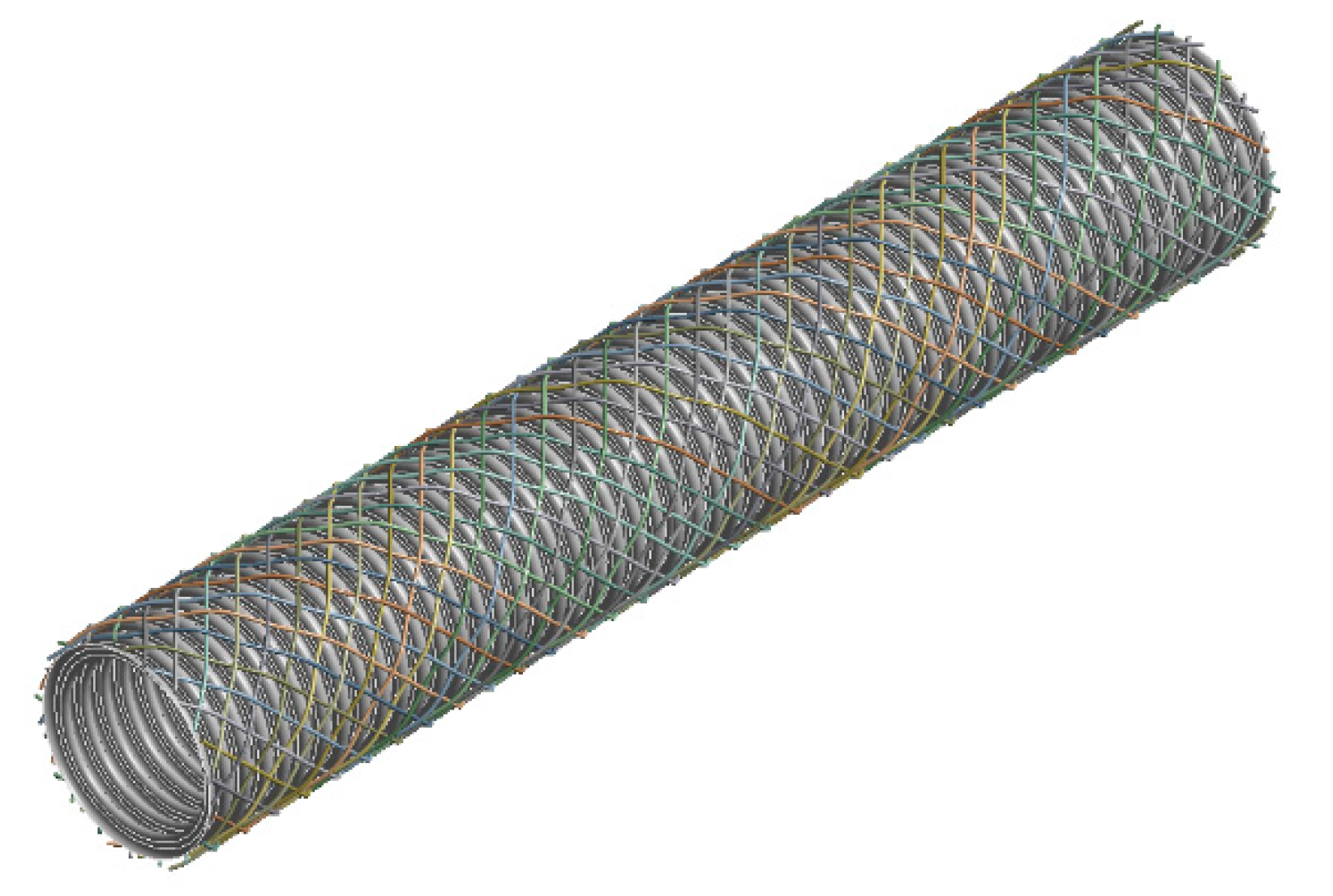
Figure 9.
Finite element model.
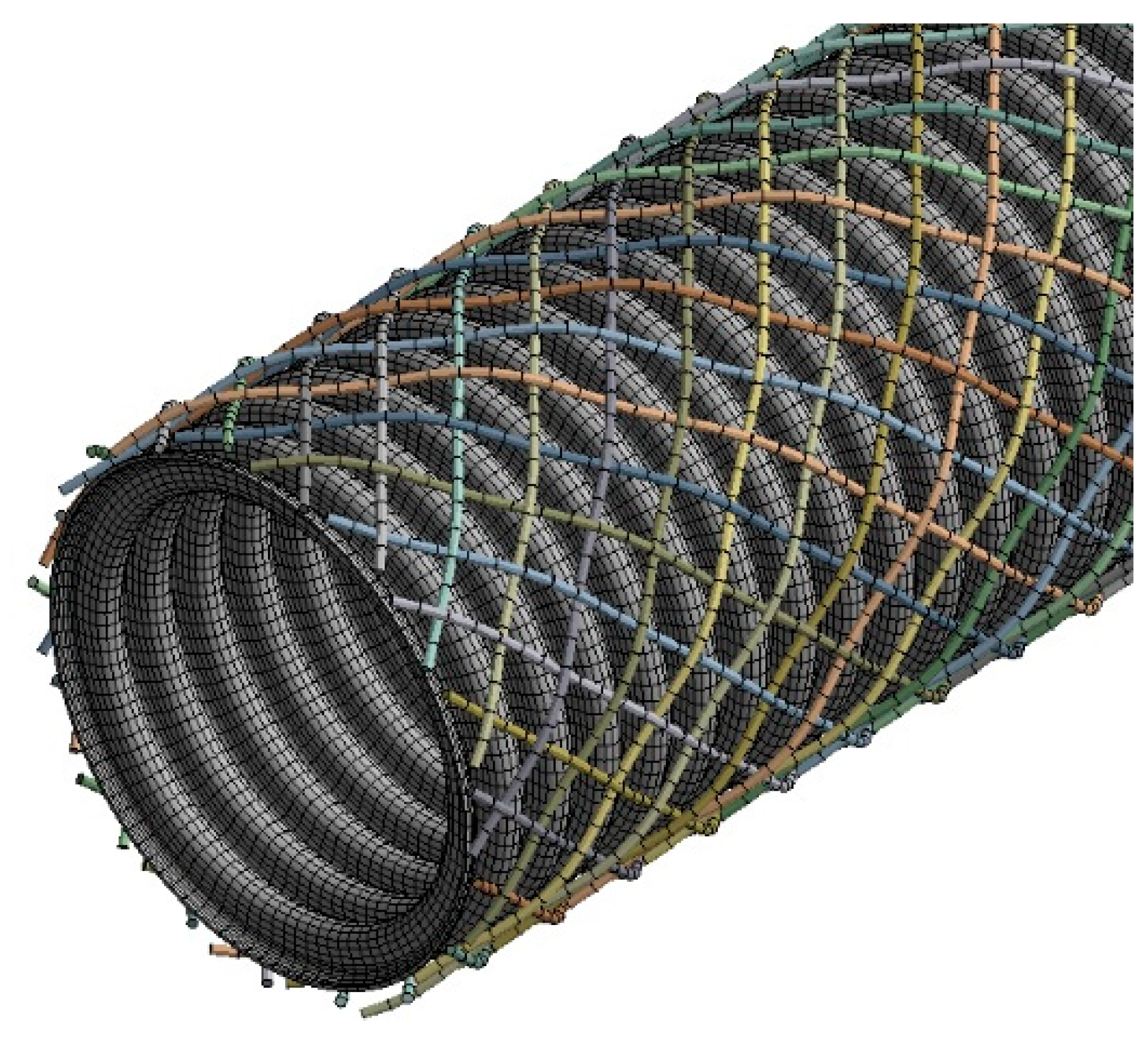
Figure 10.
Experimental boundary conditions.
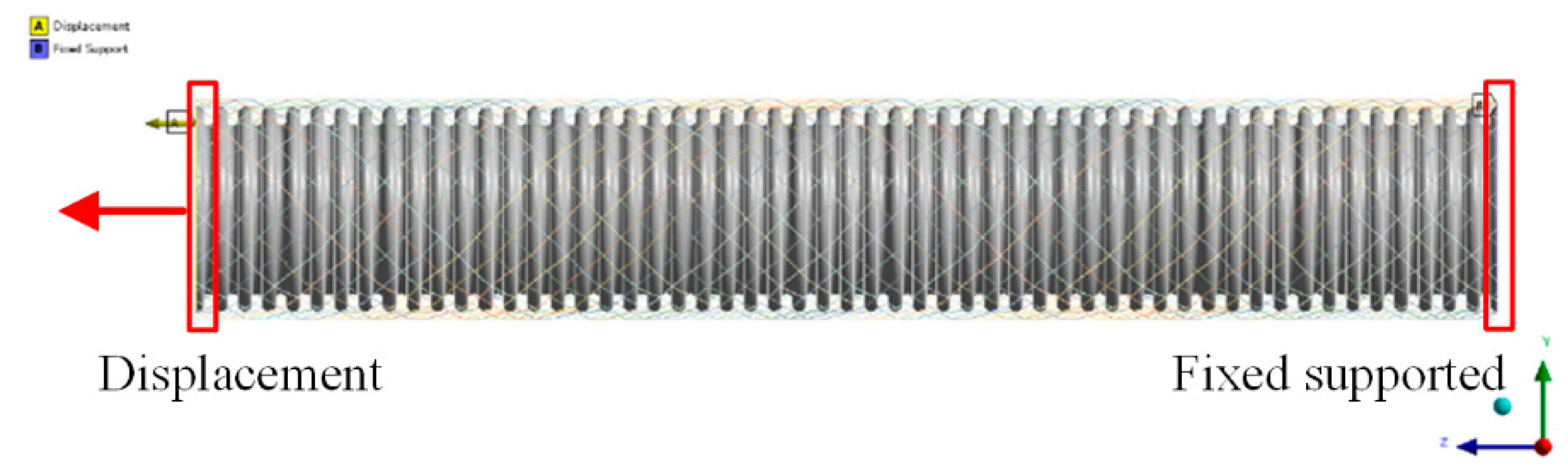
Figure 11.
Load–deformation curve.
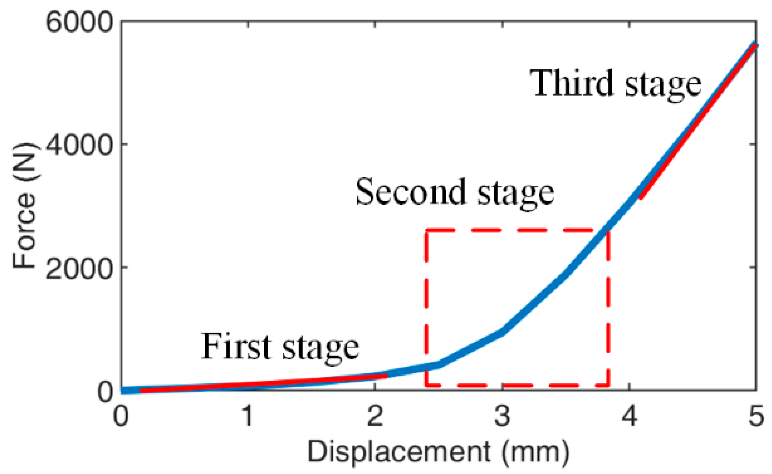
Figure 12.
Load–deformation curves for different braiding angles.
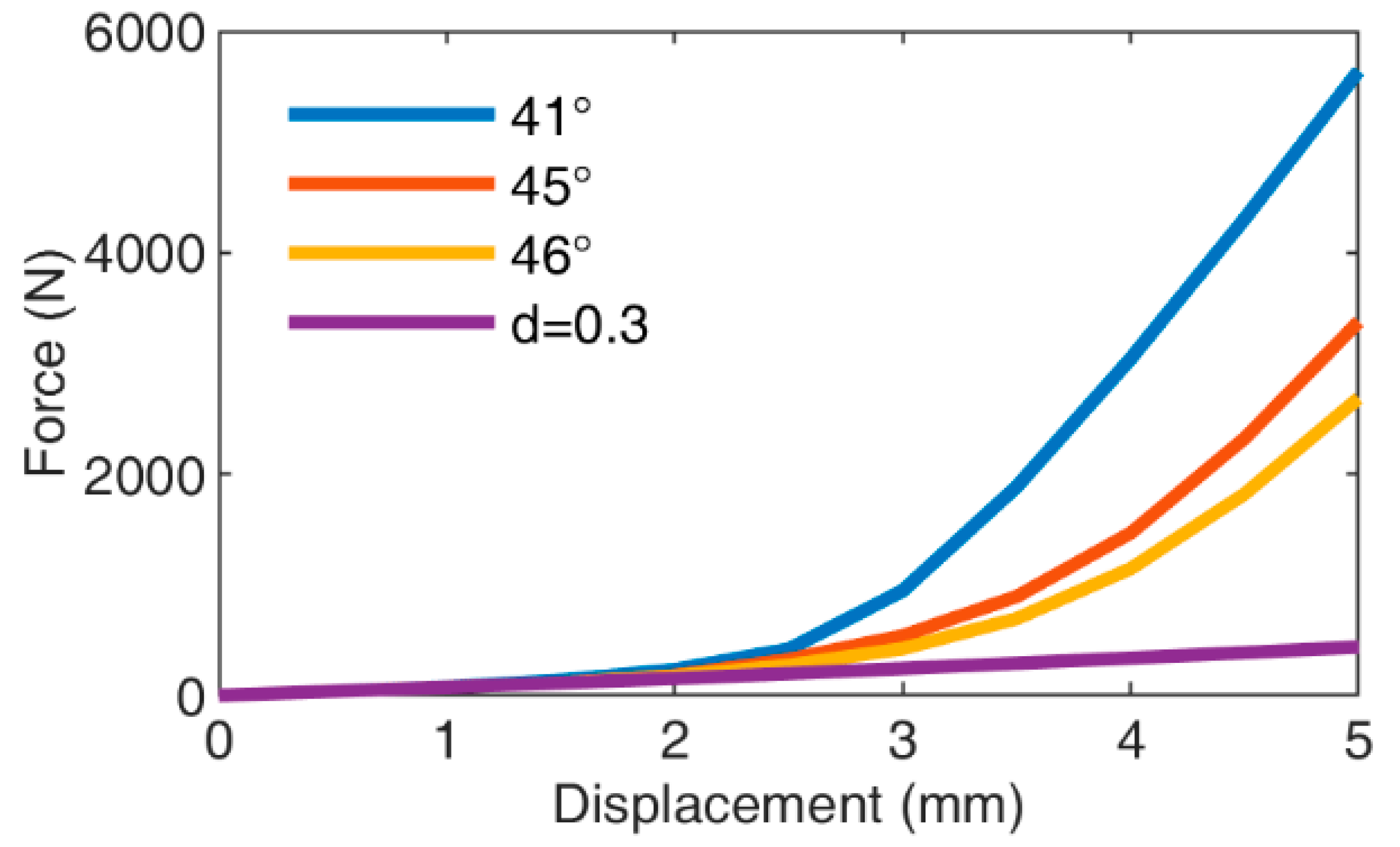
Figure 13.
Fitting curves for the braided corrugated hose: (a); (b); (c); (d) d = 0.3.

Table 1.
Physical properties of 304 stainless steel.
| Young’s Modulus /MPa | Poisson’s Ration | |||
|---|---|---|---|---|
| 0.3 |
Table 2.
Structural parameters of the metallic braided tube.
| Number | Number of Strands | Wires per Strand | Braiding Angle | Diameter of Wire /mm | Length of Unit Cell /mm |
|---|---|---|---|---|---|
| A | 36 | 1 | 41° | 0.6 | 4.4109 |
| B | 36 | 1 | 45° | 0.6 | 4.0855 |
| C | 36 | 1 | 46° | 0.6 | 4.0077 |
| D | 36 | 1 | 45° | 0.3 | 4.0855 |
Table 3.
Structural parameters of the metal bellows.
| Outer Diameter /mm | Inner Diameter /mm | Pitch of Wave /mm | Wave Height /mm | Radius of Wave Trough/mm | Radius of Wave Crest /mm | Thickness /mm | Length/mm |
|---|---|---|---|---|---|---|---|
| 31.5 | 25.4 | 3.7 | 2.8 | 0.8 | 0.8 | 0.25 | 200 |
Table 4.
Parameters of the correction coefficients in Equation (37).
| Coefficients | |||
|---|---|---|---|
| Value | 0.4578 | 0.001728 | 0.000001763 |
Publisher’s Note: MDPI stays neutral with regard to jurisdictional claims in published maps and institutional affiliations. |
© 2021 by the authors. Licensee MDPI, Basel, Switzerland. This article is an open access article distributed under the terms and conditions of the Creative Commons Attribution (CC BY) license (https://creativecommons.org/licenses/by/4.0/).
Share and Cite
MDPI and ACS Style
Huang, D.; Zhang, J. Research on the Tensile Mechanical Properties of a Braided Corrugated Hose and Its Axial Stiffness Model. J. Mar. Sci. Eng. 2021, 9, 1029. https://doi.org/10.3390/jmse9091029
AMA Style
Huang D, Zhang J. Research on the Tensile Mechanical Properties of a Braided Corrugated Hose and Its Axial Stiffness Model. Journal of Marine Science and Engineering. 2021; 9(9):1029. https://doi.org/10.3390/jmse9091029
Chicago/Turabian StyleHuang, Dacheng, and Jianrun Zhang. 2021. "Research on the Tensile Mechanical Properties of a Braided Corrugated Hose and Its Axial Stiffness Model" Journal of Marine Science and Engineering 9, no. 9: 1029. https://doi.org/10.3390/jmse9091029
Note that from the first issue of 2016, this journal uses article numbers instead of page numbers. See further details here.