Article

Optimum Arrangement Design of Mastic Ropes for Membrane-Type LNG Tanks Considering the Flatness of Thermal Insulation Panel and Production Cost

1
Department of Naval Architecture and Ocean Engineering, Seoul National University, Seoul 08826, Korea
2
Research Institute of Marine Systems Engineering, Seoul National University, Seoul 08826, Korea
3
Department of the Naval Architecture and Marine Engineering, Changwon National University, Changwon 51140, Korea
*
Author to whom correspondence should be addressed.
These authors contributed equally to this work.
J. Mar. Sci. Eng. 2020, 8(5), 353; https://doi.org/10.3390/jmse8050353
Submission received: 10 April 2020 / Revised: 12 May 2020 / Accepted: 14 May 2020 / Published: 16 May 2020
(This article belongs to the Special Issue Computer-Aided Marine Structures’ Design)

Abstract

:
Thermal insulation panels are installed on the inner walls of liquefied natural gas (LNG) tanks of an LNG carrier to maintain the cryogenic temperature. Mastic ropes are used to attach thermal insulation panels to the inner walls and to fill the gap between the walls and panels. Because the inner walls of the LNG tanks can be corrugated owing to production errors, a large amount of mastic ropes are required to maintain the flatness of the thermal insulation panels. Therefore, in this study, an optimization method is proposed to minimize the total amount of mastic ropes for satisfying the flatness criterion of thermal insulation panels. For this purpose, an optimization problem is mathematically formulated. An objective function is used to minimize the total amount of mastic ropes considering constraints to flatten the thermal insulation panels. This function is applied to the design of membrane-type LNG tanks to verify the effectiveness and feasibility of the proposed method. Consequently, we confirm that the proposed method can provide a more effective arrangement design of mastic ropes compared with manual design.

Graphical Abstract

1. Introduction

1.1. Research Background

A liquefied natural gas (LNG) carrier is a tank ship designed for transporting LNG. LNG tanks are the most important aspect in the design stage of LNG carriers. Because an LNG carrier transports low-temperature LNG, thermal insulation panels are attached to the inner walls of the LNG tank to maintain the temperature of the LNG. If the thermal insulation panels are not flat owing to the corrugation of the inner hull of the LNG tank, the thermal insulation panels may be vulnerable to impact, and the insulation efficiency may deteriorate. Therefore, wedges are placed on the vertices of the thermal insulation panels, known as studs, to flatten the thermal insulation panels. The empty space between the insulation panel and the inside hull of the LNG tank is filled with mastic ropes. The excessive use of mastic rope increases production costs. Meanwhile, using insufficient mastic ropes will not satisfy the flatness criterion.
Minimized total amount of mastic ropes and flat thermal insulation panels cannot be satisfied simultaneously because those two objectives conflict with each other. Manual designs are focused only on the flatness of the thermal insulation panels. Occasionally, workers overuse mastic ropes without guidelines. Therefore, new approaches based on optimization are required to achieve both objectives simultaneously.

1.2. Related Studies

Various studies have been performed regarding the insulation efficiency of thermal insulation panels. Jeon et al. [1] investigated a heat transfer model considering the temperature distribution of the outer hull of an LNG tank under cryogenic conditions. They discovered the effects of thermal insulation panel layers, which maintained cryogenic conditions inside the LNG tank.
Furthermore, studies have been conducted regarding the fatigue strength inside the hull of an LNG tank when the flatness of the thermal insulation panel is uneven. For example, Chun et al. [2] investigated the dynamic strength characteristics of the LNG insulation system of a membrane-type LNG tank under impact loads. They developed a custom-built-type dry drop test facility to measure the performance of the LNG insulation system, and the results can be used for the robust design and verification of numerical analyses of LNG insulation systems. Kim et al. [3] tested the fatigue strength of a membrane-type LNG tank for three different locations at room temperature, considering the sloshing impact loading condition. Consequently, they discovered the limit fatigue strength of the thermal insulation panel according to the amount of mastic ropes. Similarly, Graczyk and Moan [4] and Kim et al. [5] investigated the structural response of the inner walls of an LNG tank and the corrugation by pressure resistance through finite element analysis; they discovered the effect and importance of the flexibility of thermal insulation panels by deflection and bending.
Several studies have been performed regarding the design of LNG tanks and the cost reduction of LNG storage. Caprace et al. [6] proposed a multi-objective optimization problem for an LNG carrier considering production cost, weight, and stiffness. Furthermore, they obtained Pareto frontiers using the weighted sum of the factors and validated the results with the Bureau Veritas rules. Salarkia et al. [7] designed an LNG bi-lobe tank using finite elements, a genetic algorithm, and a neural network to suggest the maximum capacity and minimum cost of the LNG bi-lobe tank. They first used a genetic algorithm with an objective function, including the results of finite element simulation, the weight of the LNG bi-lobe tank, and the volume of the LNG bi-lobe tank.
Furthermore, they used a neural network to optimize the design parameters of the entire continuous region of the LNG bi-lobe tank. Barclay et al. [8] presented a critical study of the effects of LNG storage capacity and insulation quality. They suggested a marginal cost that involved a tradeoff between insulation quality and capital cost.
When we investigated previous studies, there are few studies closely related to mastic rope optimization. Few studies have suggested guidelines for the requirement of mastic ropes considering insulation efficiency, effect to the hull of the LNG tank, and design cost of the LNG tank. Therefore, guidelines regarding the total amount of mastic ropes considering the flatness criterion of the thermal insulation panel are proposed herein.
This paper is organized as follows. Section 2 describes the method for the optimal arrangement design of mastic ropes. Section 3 describes the application of the proposed method to the inner walls of the LNG tank; in addition, a discussion is presented with the results obtained from the application. Section 4 presents the overall results of this study and discussions of future studies.

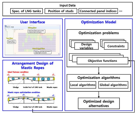
2. Arrangement Design Method of Mastic Ropes

2.1. LNG Tank Description

Figure 1 shows the overall shape and the name of each side of the membrane-type LNG tank used in this study. The membrane-type LNG tank was shaped like an octagonal prism, as shown in Figure 1.
The names of all 10 inner walls (simply, walls) were determined by the regulation. The tetragonal top and bottom sides were denoted walls A and C, respectively. The two octagonal walls were denoted wall B for the front side and wall D for the backside of the LNG tank. The other tetragon sides were denoted walls E, F, G, K, J, and H clockwise from wall B.
The octagonal LNG tank comprised 24 edges and 16 points. The name of each edge was defined with the name of the two sides that were connected with the edge. For example, the name of the edge connecting walls A and B is edge BA. The number of each vertex is shown in Figure 1, which starts from the top-left vertex counterclockwise on wall B to the top-left vertex on wall D.
To ensure that no gap exists between panels and increase the insulation efficiency, the exact specifications of each wall should be measured. Supposed that four vertices of each wall are on one plane, the X and Y positions of each vertex and the length of each edge and diagonal were measured. After measuring the specifications, reference lines were drawn horizontally and vertically with respect to the centroid of each wall. In each wall, the horizontal and vertical reference lines should be perpendicular to each other, and the reference lines divide the wall to minimize the difference of the individual area. After defining the reference lines of each wall, the stud lines were defined at equal intervals from the reference line. The point at which the stud lines intersected was known as a stud, and a wedge was installed at each stud to support the vertices of the panel, as shown in Figure 2. Because of the torsion of the inside hull, the initial height at each stud was uneven and the panel was tilted. Therefore, the initial height at each stud was measured from the reference laser plane, which was at a certain height from the floor. The wedge height at each stud was defined considering the initial heights, and the empty space under the thermal insulation panel was defined using the wedge height. Because the wedge heights differed, each panel had a different space size under the panel, and mastic ropes were used to fill the space between the panel and the inside hull of the LNG tank, as shown in Figure 3.
Figure 3 shows the manufacturing process of the LNG tank. In this figure, the inside hull of the LNG tank is located in the bottom, and the thermal insulation panels are located on the inside hull of the LNG tank. To fasten the thermal insulation panels, the wedges are located on the vertices of the thermal insulation panels and the mastic ropes are used to fill the space.
If space is enlarged, then more mastic ropes are used to fill the space, which increases the total cost. Therefore, we must optimize the wedge heights considering both the flatness of the panels and the total cost of the mastic ropes.

2.2. Formulation of the Optimization Problem

The optimization problem is composed of design variables, the objective function, and constraints. In this study, the purpose of the optimization problem is to minimize the total amount of mastic ropes while satisfying the flatness criterion; furthermore, the optimization problem is mathematically formulated. Each component of the optimization problem is described in the subsequent subsections.

2.2.1. Input Information

In this study, the X and Y positions and the initial height (P = {p1, p2, p3, …, pn}, pi = (xi, yi, zi)) at each stud was set as the input information. In particular, the initial height at each stud was defined as the distance between the inside hull of the LNG tank and the reference laser plane. The reference laser plane is the imaginary plane over the inside hull parallel with the XY-plane, as shown in Figure 4. In this figure, to calculate the initial height at each stud, it is needed to define the stud lines, and the X and Y positions of each stud, as explained in Section 2.1.
Additionally, the connected panel index (N = {N1, N2, N3, …, Nn}) at each stud was the input information.

2.2.2. Design Variables

Hundreds of studs exist in the wall of the inside hull of an LNG tank, and each stud has a wedge to support the vertices of the panel. Because the initial height of each stud was different, the wedge height at each stud must be determined to flatten the panel. Therefore, the design variables of the optimization problem were the wedge heights (X = {h1, h2, h3, …, hn}) at the studs. To determine the wedge heights, the input information of the problem must be defined. To calculate the corrugation at each stud and the slope, the X and Y positions and the initial height (P = {p1, p2, p3, …, pn}, pi = (xi, yi, zi)) at each stud were the input information.
After defining the input information, the wedge heights were determined considering the final height and slope at each stud. The wedge height increased discretely in 0.5 mm increments between 4 and 25 mm. Figure 5 shows an example with 3 × 2 thermal insulation panels and 12 studs. In the example, the input information was a set of pi for 12 studs and a set of Nj for six thermal insulation panels. The design variables of the example were the wedge heights, which were a set of hi for 12 studs.
As shown in Figure 6, the initial height at each stud was determined as the distance between the reference laser plane and the hull of the LNG tank at each stud. Because the wedge height at each stud was determined as the design variables, the final height at each stud was calculated with the difference between the initial and wedge heights at the stud, as shown in Equation (1). The zi and hi in Equation (1) denote the initial height from the reference laser plane and the wedge height at each stud, respectively.
d z i = z i h i

2.2.3. Objective Functions

In this study, the primary target of the optimization problem is to decrease the total amount of mastic ropes. As shown in Figure 7, all panels are flat in the ideal flatness condition. However, in the ideal flatness condition, more mastic ropes are used. Therefore, we can minimize the total amount of mastic ropes by maintaining the slope of the thermal insulation panels within the flatness criterion.
We optimized the wedge heights and decreased the total amount of mastic ropes based on the mastic rope optimization conditions. Five types of mastic ropes exist according to the radius or sectional area of the mastic rope. The mastic ropes were spread under the panel, and a single type of mastic rope was used in one panel. A panel comprised four wedges for four vertices, and the type of mastic rope to be used was decided by the maximum height (e) of the wedges according to the mastic rope reference shown in Table 1.
The panel was a rectangle measuring 3 m × 1 m, and the mastic ropes were spread widthwise at intervals of 100 mm. Therefore, the total length of the mastic ropes was 30 m in one panel, and the amount of mastic ropes in one panel was calculated with the total length of 30 m and the sectional area, which was decided based on Table 1.
H 1 ( X ) = 30 · ( n 1 · S 1 + n 2 · S 2 + n 3 · S 3 + n 4 · S 4 + n 5 · S 5 )
In Equation (2), H1(X) is the total amount of mastic ropes; ni and Si are the number of panels and the sectional area of type-i mastic ropes, respectively. Therefore, the objective function of the optimization problem minimizes the total amount of mastic ropes.
In addition, it is important to not only decrease the total amount of mastic ropes but also to flatten the thermal insulation panels in this study. Therefore, the objective function can be changed to flatten the thermal insulation panels. For this purpose, two types of additional objective functions are proposed instead of minimizing the total amount of mastic ropes. First, to minimize the difference between the final heights of adjacent studs, an objective function H2(X) was used. This objective function is used to flatten the thermal insulation panels with a local side.
H 2 ( X ) = | d z j d z i x j x i | + | d z k d z i y k y i |
Considering studs i and j are adjacent to the y-axis, which mean that studs i and j are placed on the same line on the y-axis, and stud k is adjacent to the x-axis. Therefore, The first term of H2(X) means the gradient of two adjacent studs on the x-axis, the second term of H2(X) means the gradient of two adjacent studs on the y-axis. The second objective function H3(X) minimizes the standard deviation of the final heights of all studs. This objective function is used to flatten the thermal insulation panels with a global side.
H 3 ( X ) = S T D E V ( d z i )
The standard deviation of the final heights of all studs is calculated with Equation (5). In this equation, μ is the average of the final heights of all studs, and the number N is the total number of studs.
S T D E V ( d z i ) = i = 1 N ( d z i μ ) 2 N ,    μ = i = 1 N d z i N
The purpose of two objective functions, H2(X) and H3(X), is to consider not only the economics of the LNG tank but also the quality of the LNG tank in terms of insulation efficiency and strength. Here, the objective function H2(X) is considering the flatness of the thermal insulation panels in view of the local side. In comparison, the H3(X) is considering the flatness of the thermal insulation panels in view of the global side of the whole wall.

2.2.4. Constraints

Although the primary target of the optimization problem is to decrease the total amount of mastic ropes, the flatness criterion must be satisfied as well. Three types of constraints pertaining to the gradients of the wedges and panels were used in this study. First, the gradient between two adjacent studs in the x- and y-directions is a constraint. The constraint related to the gradient between two adjacent studs can be calculated using Equation (6) for the x- and y-directions.
| d z j d z i x j x i | < ε 1 ,    | d z k d z i y k y i | < ε 1
Considering studs i and j are adjacent to the y-axis, which mean that studs i and j are placed on the same line on the y-axis, and stud k is adjacent to the x-axis. Therefore, two inequalities mean the gradient constraints to x- and y-direction, similar to the objective function H2(X). In Equation (6), the maximum gradient should be less than the criterion ε1, and the value of ε1 is 3 mm per 1 m in this study.
Next, the twist of each panel is a constraint as well. Even though the gradient between two adjacent studs is satisfied with the first constraint, the panels can be twisted because no constraints exist between diagonal studs. The twist of the panel can be calculated as the difference between the maximum and minimum values of the final height at four studs in a panel, as shown in Equation (7).
| max ( d z ) min ( d z ) | p a n e l < ε 2
In Equation (7), dz means the set of stud heights that supports one panel, and it is composed of four studs for four vertices of the panel. The max(dz) is the maximum value, and the min(dz) is the minimum value of the final height at the four studs in one panel. Therefore, this equation means that the difference between the maximum and minimum values of the final height at the four studs should be less than that of criterion ε2, and the value of ε2 was 4 mm in this study.
Finally, the difference between two adjacent gradients for the x- and y-directions is a constraint as well, as shown in Equation (8).
| d z l d z j x l x j d z j d z i x j x i | < ε 3 ,    | d z m d z k y m y k d z k d z i y k y i | < ε 3
In Equation (8), studs i, j, and l are adjacent to the y-axis, and stud j is the middle stud between studs i and l. Meanwhile, studs i, k, and m are adjacent to the x-axis, centering around stud k. In this equation, the difference between two adjacent gradients should be less than that of criterion ε3, and the value of ε3 was 3 mm per 1 m, i.e., the same as that of ε1 in this study.
The first and second constraints are related to the slope or twist in one panel; however, the slope between panels must be considered as well. Therefore, the last constraint represents the slope between panels adjacent to the x- and y-directions. If no constraint exists regarding the slope between panels, then the panels cannot maintain the flat condition. Therefore, this optimization problem is a type of constrained optimization problem that comprises many design variables, one objective function, and three forms of inequality constraints.
With the example based on the 3 × 2 panels and 12 studs as shown in Figure 5, 15 constraints exist for the gradient between two adjacent studs, nine constraints for the x-direction, and six constraints for the y-direction. Furthermore, because each panel has a constraint for the twist, six constraints exist for the six panels. Finally, six constraints exist for the x-direction and three constraints for the y-direction for the slope between two adjacent panels.

2.3. Optimization Algorithm

Generally, optimization algorithms comprise two types of algorithms: global and local optimization algorithms. A few types of local optimization algorithms, including sequential linear programming [9], sequential quadratic programming [10], and a method for feasible directions [11] can be used to obtain the optimum solution effectively. However, if the problem contains many design variables and becomes complicated, the local optimization algorithms obtain a local optimum that is relatively close to the starting point.
To overcome the limitation of local optimization, we used the nondominated sorting genetic algorithm (NSGA)-II [12] global optimization algorithm, which is a well-known and proven genetic algorithm [13,14]. The NSGA-II algorithm shows good performance to find the global optimal solution for non-linear optimization problems. Generally, the genetic algorithm starting from a random initial population selects the best solution set in the current generation and obtains the optimum solution via crossover and mutation [15,16,17]. However, because the mastic rope optimization problem involves many design variables and constraints, it is difficult to obtain the optimum solution that satisfies all constraints from the random initial population. Therefore, the seed solution that is calculated from the last optimization and satisfies all constraints was used as one of the initial solutions; this is known as a seed-based genetic algorithm [18]. In this study, hundreds of design variables and thousands of constraints exist in the wall of the LNG tank. Therefore, a seed that satisfies all constraints at the minimum was used to obtain the global optimum effectively for the optimization problem having many design variables and constraints. The minimum condition seed is based on an approach to minimize the total amount of mastic ropes. Figure 8 shows the overall process of the seed-based genetic algorithm.

2.4. Summary of the Proposed Method for Mastic Rope Optimization

As described previously, the optimization problem for mastic ropes can be summarized as follows:
Find X = { h 1 , h 2 , h 3 , , h n } : Design variables
Minimize H 1 ( X ) = 30 · ( n 1 · S 1 + n 2 · S 2 + n 3 · S 3 + n 4 · S 4 + n 5 · S 5 ) ,
H 2 ( X ) = | d z j d z i x j x i | + | d z k d z i y k y i | ,
and H 3 ( X ) = S T D E V ( d z i )
: Objective functions
Subject to | d z j d z i x j x i | < ε 1 ,    | d z k d z i y k y i | < ε 1 ,
| max ( d z ) min ( d z ) | p a n e l < ε 2 ,
and | d z l d z j x l x j d z j d z i x j x i | < ε 3 ,    | d z m d z k y m y k d z k d z i y k y i | < ε 3
: Constraints
Herein, the optimization problem is proposed to decrease the total amount of mastic ropes satisfying the flatness criterion of thermal insulation panels for the design of a membrane-type LNG tank.
The design variables of the optimization problem are the heights of the wedges that support and decrease the slope of the panels. The objective function minimizes the total amount of mastic ropes, and three types of constraints exist regarding the gradient of two adjacent studs, the twist of panels, and the difference between the two adjacent gradients. To solve the constrained optimization problem, the seed-based genetic algorithm with NSGA-II, which is one of the global optimization algorithms, was used.

3. Applications of the Proposed Method

To solve the mastic rope optimization problem, we developed a prototype program based on the proposed method. To verify the feasibility and applicability of the program, we applied it to wall A of the membrane-type LNG tank and compared the results with the manual design.

3.1. Prototype Program for the Proposed Method

The prototype program is composed of the LNG tank generation module, the optimization module, and a user interface. The prototype program is an in-house program developed using the C# language in the Microsoft Visual Studio 2017 environment. Using the program, the user can easily perform mastic rope optimization and review the results. Figure 9 shows a screenshot of the prototype program.
In the prototype program, the user interface comprised four types of views. First, the ribbon and tree views generate the LNG tank and import or export the results. Next, the data view shows the specifications of each stud, including the wedge number, initial height, final height, wedge height, and connected panel number. Finally, the panel view shows the visualization of the result of mastic rope optimization, and the color of each panel represents the type of mastic rope that is used on the panel. Gray, blue, green, yellow, and red panels represent mastic ropes of types C1, C2, C3, C4, and C5, respectively.

3.2. Definition of Various Cases with the Proposed Method

The prototype program demands the specifications of each stud, including the location, stud number, initial height, and connected panel number, as input data. The test case that is the tetragonal wall A of the membrane-type LNG tank contains 360 panels, 418 studs (design variables), and 1910 constraints.
As explained in Section 2, the objective function of this study can be changed for the optimization problem. In this study, to compare the difference in the optimization result based on various purposes, we performed several cases of changing the objective function. The cases are divided into three according to objective functions as following:
-
Case 1: H1(X), to minimize the total amount of mastic ropes
-
Case 2: H2(X), to minimize the difference between the final heights of the adjacent studs
-
Case 3: H3(X), to minimize the standard deviation of the final heights of all studs
First, Case 1 contained the H1(X) objective function to minimize the total amount of mastic ropes. In Cases 2 and 3, the objective function was changed to H2(X) and H3(X), respectively, to minimize the difference between the final heights of the adjacent studs and to minimize the standard deviation of the final heights of all studs. As explained in Section 2, each objective function H2(X) and H3(X) represents the local and global sides of the flatness of the thermal insulation panels, respectively. Therefore, the total amount of mastic ropes and the flatness of the thermal insulation panels were compared according to the objective function for Cases 1, 2, and 3.

3.3. Result and Discussion

In Table 2, the number of Ci type (i = 1 to 5) is the number of panels that use the Ci-type mastic rope. For example, two panels use the C1-type mastic ropes; 214 panels use the C2-type mastic ropes; and 86, 43, 5 panels use the C3-, C4-, and C5-type mastic ropes in the manual design, respectively. However, 246 panels were used in the proposed method. Because the manual design is focused on the flatness between the panels, the proposed method decreases the total amount of mastic ropes by reducing the usage of the C3 type, which has a larger sectional area compared with the C2 type. This means that the total amount of mastic ropes will be increased if mastic ropes of types C3, C4, and C5 (green, yellow, and red panels, respectively) are increased.
Furthermore, we compared the average wedge height between the manual design and the proposed method, because the decrease in the average wedge height can increase the available capacity of the LNG tank because the panels would be closer to the hull of the LNG tank, as shown in Figure 10. From this comparison with the manual design, we can see that the proposed method can increase the capacity of the LNG tank; furthermore, it can increase the economics of the LNG tank.
Table 2 shows the detailed results of the proposed method. In this study, the primary target of the proposed method was H1(X), which means to minimize the total amount of mastic ropes. The relative and total amounts of mastic ropes between the proposed method and the manual design are compared in Figure 11.
In Case 1, the total amount of mastic ropes decreased by approximately 3%, and the average wedge height decreased by approximately 8% compared with the manual design. The result of Case 1 shows the greatest decreased rate for both the total amount of mastic ropes (H1(X)) and average wedge height. This means that a higher capacity can be set for the LNG tank with a lower cost in Case 1. Furthermore, the height difference between adjacent studs (H2(X)) and the standard deviation of all studs (H3(X)) decreased by approximately 2% in Case 1 compared with the manual design. This means that the mastic rope optimization shows more flatness of the thermal insulation panels than the manual design. Therefore, the maximized economical design of the LNG tank can be obtained in Case 1.
Because the purpose of Cases 2 and 3 is to decrease the slope between two adjacent panels, the total amount of mastic ropes (H1(X)) increased only slightly compared with the manual design because the number of panels using C3-, C4-, and C5-type mastic ropes increased. However, in both cases, the average wedge height decreased compared with the manual design. Furthermore, the height difference between adjacent studs (H2(X)) and the standard deviation of all studs (H3(X)) decreased significantly in Case 2, i.e., approximately 23% and 15%, respectively; and approximately 12% and 29%, respectively, compared with the manual design. Therefore, the flatness of the thermal insulation panels increased in Cases 2 and 3 without decreasing the economics of the LNG tank significantly. This means that Cases 2 and 3 can be used to consider both the economics and flatness of the thermal insulation panels. Figure 12 shows a visualization of the result of mastic rope optimization for all cases.
Figure 12 shows the visualization of the optimization results of Case 1, 2, and 3. We can see that the larger number of C2-type matric ropes is used, the smaller amount of mastic ropes is used. Case 1, 2, and 3 uses 247, 232, and 202 of C2-type mastic ropes, respectively. Therefore, the smallest amount of mastic ropes was used for Case 1, whereas the largest amount was used for Case 3.

4. Conclusions and Future Work

In this study, an efficient method for mastic rope optimization, considering both the total amount of mastic ropes and the flatness of the thermal insulation panels, was mathematically formulated as an optimization problem. With the input information of studs, the set of wedge height at each stud was considered as the design variable, and the total amount of mastic ropes was used as the objective function to minimize the amount of mastic ropes. In the process, three types of constraints were defined in relation to the slope between adjacent studs and the twist of panels to satisfy the flatness criterion. To solve the complicated optimization problem with the numbers of design variables and constraints, the initial solution set that satisfied all constraints was used as the seed for the genetic algorithm. Consequently, the total amount of mastic ropes decreased by approximately 3%, and the average wedge height decreased by approximately 8% compared with the manual design. The cost of mastic ropes could be calculated with the price per unit volume of the mastic ropes. The decrease in the total amount of mastic ropes leads to a reduction in the total cost of mastic ropes. Also, the reduction in the average wedge height results in an increase in the available capacity of the LNG tank. As a result, these improvements will bring us hundreds of thousands of dollars in savings. These results indicated that the proposed method provided an efficient arrangement design of mastic ropes in terms of the economics of the LNG tank.
Furthermore, with the various purposes of mastic rope optimization, the objective function was changed to minimize the difference between the final heights of adjacent studs and minimize the standard deviation of the final heights of all studs. By changing the objective function, the proposed method required a slightly increased total amount of mastic ropes, but the average wedge height decreased compared with that of the manual design. Therefore, the results demonstrated that the proposed method can select the objective function based on the purpose, the most economical arrangement design, or both the economics and quality of the LNG tank.
In the future, other global optimization algorithms will be performed to compare the results and the computation time of mastic rope optimization. Using various global optimization algorithms [19,20,21] and tools [22,23], we expect that we can find a better solution than that of this study. Furthermore, the proposed method will also be applied to the problems for different types of LNG tanks to enhance the usability of the proposed method.

Author Contributions

Conceptualization, D.-H.C., M.-I.R. and S.-H.H.; methodology, D.-H.C. and M.-I.R.; software, D.-H.C. and S.-H.H.; validation, D.-H.C. and M.-I.R.; formal analysis, D.-H.C. and M.-I.R.; investigation, D.-H.C. and S.-H.H.; resources, M.-I.R. and S.-H.H.; data curation, D.-H.C. and S.-H.H.; writing—original draft preparation, D.-H.C., M.-I.R. and S.-H.H.; writing—review and editing, D.-H.C., M.-I.R. and S.-H.H.; visualization, D.-H.C., M.-I.R. and S.-H.H.; supervision, M.-I.R.; project administration, M.-I.R.; funding acquisition, M.-I.R. All authors have read and agreed to the published version of the manuscript.

Funding

This work was partially supported by (a) Hyundai Heavy Industries, Co., Ltd., Republic of Korea, (b) BK21 Plus, Education & Research Center for Offshore Plant Engineers (COPE) of Seoul National University, Republic of Korea, and (c) Research Institute of Marine Systems Engineering of Seoul National University, Republic of Korea.

Conflicts of Interest

The authors declare no conflict of interest. The funders had no role in the design of the study; in the collection, analyses, or interpretation of data; in the writing of the manuscript, or in the decision to publish the results.

References

  1. Jeon, S.J.; Jin, B.M.; Kim, Y.J.; Chung, C.H. Consistent thermal analysis procedure of LNG storage tank. Struct. Eng. Mech. 2007, 25, 445–466. [Google Scholar] [CrossRef]
  2. Chun, M.S.; Kim, M.H.; Kim, W.S.; Kim, S.H.; Lee, J.M. Experimental investigation on the impact behavior of membrane-type LNG carrier insulation system. J. Loss Prev. Process Ind. 2009, 22, 901–907. [Google Scholar] [CrossRef]
  3. Kim, M.H.; Lee, S.M.; Lee, J.M.; Noh, B.J.; Kim, W.S. Fatigue strength assessment of MARK-III type LNG cargo containment system. Ocean Eng. 2010, 37, 1243–1252. [Google Scholar] [CrossRef]
  4. Graczyk, M.; Moan, T. Structural response to sloshing excitation in membrane LNG tank. J. Offshore Mech. Arct. Eng. 2010, 133, 021103. [Google Scholar] [CrossRef]
  5. Kim, B.C.; Yoon, S.H.; Lee, D.G. Pressure resistance of the corrugated stainless steel membranes of LNG carriers. Ocean Eng. 2011, 38, 592–608. [Google Scholar]
  6. Caprace, J.D.; Bair, F.; Rigo, P. Scantling multi-objective optimisation of a LNG carrier. Mar. Struct. 2010, 23, 288–302. [Google Scholar] [CrossRef]
  7. Salarkia, M.; Golabi, I.; Amirsalari, B. Optimum Design of Liquified Natural Gas Bi-lobe Tanks using Finite Element, Genetic Algorithm and Neural Network. J. Appl. Comput. Mech. 2020, in press. [Google Scholar] [CrossRef]
  8. Barclay, J.A.; Corless, A.J.; Nelson, E.H. Optimized LNG Storage Tanks for Fleet-Size Refueling Stations with Local LNG Liquefiers. Adv. Cryog. Eng. 1998, 1199–1206. [Google Scholar]
  9. Fletcher, R.; de la Maza, E.S. Nonlinear programming and nonsmooth optimization by successive linear programming. Math. Program. 1989, 43, 235–256. [Google Scholar] [CrossRef]
  10. Arora, J. Introduction to Optimum Design; Elsevier: Amsterdam, The Netherlands, 2012. [Google Scholar]
  11. Vanderplaats, G.N. Numerical Optimization Techniques for Engineering Design: With Applications; McGraw-Hill: New York, NY, USA, 1984. [Google Scholar]
  12. Deb, K.; Pratap, A.; Agarwal, S.; Meyarivan, T. A fast and elitist multiobjective genetic algorithm: NSGA-II. IEEE Trans. Evol. Comput. 2002, 6, 182–197. [Google Scholar] [CrossRef] [Green Version]
  13. Goldberg, E.D. Genetic Algorithms in Search, Optimization, and Machine Learning; Addison-Wesley: Boston, MA, USA, 1989. [Google Scholar]
  14. Davis, L. Handbook of Genetic Algorithms; Van Nostrand Reinhold: New York, NY, USA, 1991. [Google Scholar]
  15. Lee, K.-Y.; Roh, M.-I. An Efficient Genetic Algorithm Using Gradient Information for Ship Structural Design Optimization. J. Ship Technol. Res. 2001, 48, 161–170. [Google Scholar]
  16. Lee, K.-Y.; Roh, M.-I. A Hybrid Optimization Method for Multidisciplinary Ship Design. J. Ship Technol. Res. 2000, 47, 181–185. [Google Scholar]
  17. Lee, K.-Y.; Roh, M.-I.; Cho, S.H. An Efficient Global-Local Hybrid Optimization Method Using Design Sensitivity Analysis. Int. J. Veh. Des. 2002, 28, 300–317. [Google Scholar] [CrossRef]
  18. Lee, S.-M. A Study on the Method of Simultaneous Determination of Path and Speed for Ship Route Planning. Master’s Thesis, Seoul National University, Seoul, Korea, 2017. [Google Scholar]
  19. Kaur, G.; Arora, S. Chaotic Whale Optimization Algorithm. J. Comput. Des. Eng. 2018, 5, 275–284. [Google Scholar] [CrossRef]
  20. Kohli, M.; Arora, S. Chaotic Grey Wolf Optimization Algorithm for Constrained Optimization Problems. J. Comput. Des. Eng. 2018, 5, 458–472. [Google Scholar] [CrossRef]
  21. Kyuncu, H.; Ceylan, R. A PSO Based Approach: Scout Particle Swarm Algorithm for Continuous Global Optimization Problems. J. Comput. Des. Eng. 2019, 6, 129–142. [Google Scholar] [CrossRef]
  22. Jakica, N.; Zanelli, A. Knowledge based Expert System Tool for Optimization of the Complex Glass BIPV System Panel Layout on the Cable Net Structural Skin. Energy Procedia 2015, 78, 2226–2231. [Google Scholar] [CrossRef] [Green Version]
  23. Cucinotta, F.; Raffaele, M.; Salmeri, F. A Topology Optimization of a Motorsport Safety Device. In International Conference on Design, Simulation, Manufacturing: The Innovation Exchange; Springer: Cham, Switzerland, 2019; pp. 400–409. [Google Scholar]
Figure 1. Overall shape of the membrane-type liquefied natural gas (LNG) tank.
Jmse 08 00353 g001
Figure 2. Overall mastic rope optimization of LNG tank.
Jmse 08 00353 g002
Figure 3. Manufacturing process of LNG tank with thermal insulation panels and mastic ropes.
Jmse 08 00353 g003
Figure 4. Elevation view of the inside hull of LNG tank and reference laser plane.
Jmse 08 00353 g004
Figure 5. Example of input information and design variables.
Jmse 08 00353 g005
Figure 6. Elevation view of the inside hull of LNG tank and calculation of final height at each stud.
Jmse 08 00353 g006
Figure 7. Difference between ideal flatness and mastic rope optimization.
Jmse 08 00353 g007
Figure 8. Overall process of the seed-based genetic algorithm.
Jmse 08 00353 g008
Figure 9. Screenshot of the prototype program for mastic rope optimization.
Jmse 08 00353 g009
Figure 10. Increasing the capacity of LNG tank by decreasing the average wedge height.
Jmse 08 00353 g010
Figure 11. Graphs of the relative and total amounts of mastic ropes.
Jmse 08 00353 g011
Figure 12. Visualization of the results of all cases by using the proposed method.
Jmse 08 00353 g012
Table 1. Mastic rope reference table.
Maximum Wedge Height (mm)Type of Mastic RopeSectional Area (mm2)
e < 7C1200
7 < e < 12C2350
12 < e < 15C3430
15 < e < 20C4580
20 < e < 25C5720
Table 2. Result of the proposed method for all cases.
ItemManual DesignCase 1Case 2Case 3
Number of C1 types2---
Number of C2 types214246232202
Number of C3 types86716393
Number of C4 types43274146
Number of C5 types54127
Total amount of mastic ropes (H1(X))3895.36 L3784.76 L (3% decreased)3939.88 L (1% increased)3987.48 L (2% increased)
Height difference between adjacent studs (H2(X))1.62 mm1.58 mm (2% decreased)1.25 mm (23% decreased)1.41 mm (12% decreased)
Standard deviation of all studs (H3(X))8.337.24 (2% decreased)7.06 (15% decreased)5.89 (29% decreased)
Average wedge height10.7 mm9.9 mm (8% decreased)10.2 mm (5% decreased)10.4 mm (3% decreased)

