Article

Hybrid Model Predictive Control of a Two-Body Wave Energy Converter with Mechanically Driven Power Take-Off

1
Institute of Marine Science and Technology, Shandong University, Qingdao 266237, China
2
School of Mechanical Engineering, Key Laboratory of High-Efficiency and Clean Mechanical Manufacture of Ministry of Education, National Demonstration Center for Experimental Mechanical Engineering Education, Shandong University, Jinan 250061, China
*
Authors to whom correspondence should be addressed.
These authors contributed equally to this work.
J. Mar. Sci. Eng. 2023, 11(8), 1618; https://doi.org/10.3390/jmse11081618
Submission received: 2 July 2023 / Revised: 7 August 2023 / Accepted: 16 August 2023 / Published: 18 August 2023
(This article belongs to the Section Marine Energy)

Abstract

:
In this paper, a variable damper is proposed to regulate the efficiency of a two-body wave energy converter (WEC) with mechanically driven power take-off (PTO). The variable damper introduces logic constraints into the WEC system, which can be translated into a mixed logical dynamical form with the dynamics of real-valued variables, the dynamics of logic variables, and their interactions. A hybrid model predictive control (MPC) method is used to determine the control inputs, which has the capacity to handle various constraints. The performance is assessed through simulations to evaluate the effectiveness of the proposed method. The achievable performance improvements of the proposed hybrid MPC are shown by means of comparative analysis with uncontrolled WEC devices. The results show that the proposed hybrid MPC has a high requirement on the lower bound of the variable damper and the maximum damping is used only at low relative velocities to achieve the optimum phase, like latching control. The hybrid MPC performs exceptionally well under wave conditions with a small significant wave height and long wave period, improving the power generation of the uncontrolled system up to 22.5%. And, the prediction error has a significant effect on hybrid MPC performance, especially for long prediction horizon.

1. Introduction

Among renewable energy resources, ocean wave energy has the advantages of high energy density and continuous power supply [1,2]. The tremendous potential of wave energy has attracted much research interest to wave energy conversion technologies. While the breadth of knowledge and technologies has become quite large, the commercial exploitation of wave energy is still non-operational due to the high levelized cost of energy (LCOE).
The implementation of an advanced control strategy is an efficient way to improve conversion efficiency and lower the LCOE of WECs. An ideal control technique is the reactive control method, also known as complex conjugate control, which calls for the system to function as a motor in order to achieve the optimum phase and amplitude of WEC oscillation velocity [3]. It is desirable that the PTO machinery has high energy conversion efficiency to return some energy during part of the oscillation cycle [4]. However, returning the necessary amount of energy is difficult for PTO machinery, which means that reactive control cannot be implemented in practice. Budal and Falnes [5] proposed a latching control method, which can only be applied to devices with a resonant period shorter than the dominant wave period [6]. The latching control is implemented by locking the PTO for certain time intervals to lower the resonant frequency of the device to match the incident wave frequency. Declutching control is a counterpart to latching control, which is suitable for devices with a resonant period longer than the dominant wave period [7]. The declutching control method is implemented by bypassing the PTO mechanism for certain time intervals to increase the resonant frequency of the device to match the incident wave frequency. Both latching control and declutching control are not optimal control strategies for WEC devices since they simply seek to reach the ideal phase conditions while ignoring the optimum amplitude. A combination of latching control and declutching control that can switch between power generation, latching mode, and declutching mode was proposed by Feng and Kerrigan [8]. The latching–declutching control can extend the range of wave periods to make the WEC generate more electricity. These control methods are easily implemented in idealized cases for monochromatic waves and inactive physical constraints. However, they are too complicated to be implemented in realistic scenarios because the device performance is difficult to be evaluated in terms of the requirements of the method [9] and the latching or declutching time is difficult to be determined for various sea states.
The development of advanced control strategies for constrained WECs is necessary to improve the energy harvest as much as possible while maintaining safe operation. The energy maximization for WEC devices can be regarded as a constrained optimal control problem, which is noncausal [10] and needs to be combined with a wave excitation force prediction algorithm. MPC is suitable for the WEC control problem since various constraints can be easily handled, and the prediction of wave excitation can be explicitly incorporated. Lin and Huang [11] proposed a reactive rollout MPC formulation that introduces a terminal value function and a terminal constraint set to improve the energy extraction of WEC by taking into account additional future wave information. The proposed method has significant superiority over the traditional MPC, especially in the case of a short optimization horizon. To improve the accuracy of the WEC model and reduce the computational burden, Li et al. [9] proposed an improved MPC with sliding mode control, where the sliding mode control is employed to compensate for the model mismatch. The improved MPC is widely feasible for different processers and sea conditions by adjusting the proper parameters while maintaining high energy conversion efficiency. Sergiienko et al. investigated [12] the effect of MPC parameters, including prediction horizon and control force penalties, on the design of a PTO system. Approximate control force penalty terms can significantly reduce the requirements for peak control force and slew rate. Faedo et al. [13] provided a critical comparison of the MPC and MPC-like algorithms, while the MPC algorithms within the broader context of other “optimal” control schemes were presented.
In the previously mentioned investigations, it is assumed that the PTO force is controllable, and the PTO force is usually regarded as the optimization variable in the optimal control problem of WEC. However, there are differences in how accurately forces can be achieved for the wide range of PTO systems. The hydraulic PTO system is frequently employed in the design of WEC due to its advantages of having high technology maturity and a huge power load capacity [14]. However, hydraulic leakage, which is the primary concern for the marine environment, and the costly regular maintenance as a result of the complexity of hydraulic transmission are the drawbacks of the hydraulic PTO system [15]. Another type of PTO system is the pneumatic air turbine, mainly used in oscillating water column devices. The fact that key components of the air turbine PTO system are situated above water significantly enhances the reliability and maintainability of the WEC device. However, the main drawbacks come from the challenges associated with the compressibility of the air and the directional airflow, which make the system less efficient in energy conversion [16]. The hydraulic motor and pneumatic air turbine transmission systems require a fluid power transfer medium to accomplish the energy conversion, which is inevitably accompanied by energy loss. The direct mechanical drive system converts the mechanical energy directly into electricity with up to 97% efficiency [17]. Li et al. [18] designed a self-reactive WEC based on a ballscrew PTO. Martin et al. [19] analyzed and validated a two-body WEC with a ballscrew using numerical methods and wave tank testing. A key component of a mechanically driven PTO is the mechanical motion rectifier, which can convert bidirectional wave motion into a unidirectional input at the generator shaft. However, one main drawback of the mechanical drive PTO is that it is difficult to be controlled. Yang et al. [20] proposed a new PTO based on an active mechanical motion rectifier, which can achieve the controllability of the WEC device while guaranteeing unidirectional transmission. Li et al. [21] proposed a variable inertia flywheel to directly manipulate the equivalent mass of the WEC device with the aim of altering the system resonance frequency and power absorption bandwidth. The numerical studies showed that the variable inertia wheel has the capacity to adapt to various wave conditions and increase power output. Yang et al. [22] investigated the meshing and overrunning phases due to the introduction of a variable inertia flywheel with a passive configuration and verified through experiments that the variable inertia wheel is beneficial in improving energy conversion efficiency.
In this study, the realistic feasibility of the control of the WEC is considered and a hybrid MPC method is proposed. The control mechanism is a variable damper, which has proven applications in various industries and is placed in parallel with the PTO in the WEC system. In order to verify the superiority of the proposed method, the hybrid MPC method and no-control WEC are simulated and analyzed under different wave conditions. Additionally, the control performances under various parameter conditions are compared to explore the influence and function of parameters in the proposed strategy on the two-body WEC.
The rest of the paper is organized as follows. In Section 2, the forces on the two-body WEC are analyzed, and the state-space model is established. Section 3 introduces the proposed hybrid MPC method. Section 4 investigates the effects of constraints and parameters in the proposed method on the two-body WEC. Section 5 concludes the research.

2. Wave Energy Converter Model

2.1. Structure

The two-body point absorber WEC considered in this paper is shown in Figure 1. It consists of a float, a reaction section, a PTO system, and a control system. The reaction section consists of a spar and a heave plate. The PTO system consists of a ballscrew, a ballscrew nut, a gearbox, and a generator. The relative motion between the float and reaction section, driven by incident waves, is converted into rotation motion of the PTO system through the inverse driven mode of the ballscrew and ballscrew nut. The rotation motion is amplified by the gearbox and drives a generator to generate electricity into the battery. The control system changes the internal damping of the WEC through a variable damper, which is placed in parallel with the PTO system.
Only the heave motion of WEC is considered in this study. The equations of motion for the WEC can be expressed as follows [23]:
m 1 x ¨ 1 = F e x c 1 + F r a d 11 + F r a d 12 + F b 1 + F p t o + F u m 2 x ¨ 2 = F e x c 2 + F r a d 21 + F r a d 22 + F b 2 F p t o F u
where subscripts “1” and “2” represent the float and reaction section, respectively; m is the dry mass; x is the heave displacement with respect to the equilibrium position; Fexc represents the wave excitation force; Fradij is the radiation force imposed on the body i by the oscillation of the body j; Fb is the net buoyancy restoring force; Fpto is the PTO force; and Fu is the control force. The wave excitation force Fexc, radiation force Frad, and net buoyancy restoring force Fb are hydrodynamic forces, which can be calculated using hydrodynamic coefficients provided by frequency-domain boundary element method (BEM) solvers, such as WAMIT, AQWA, and NEMOH.

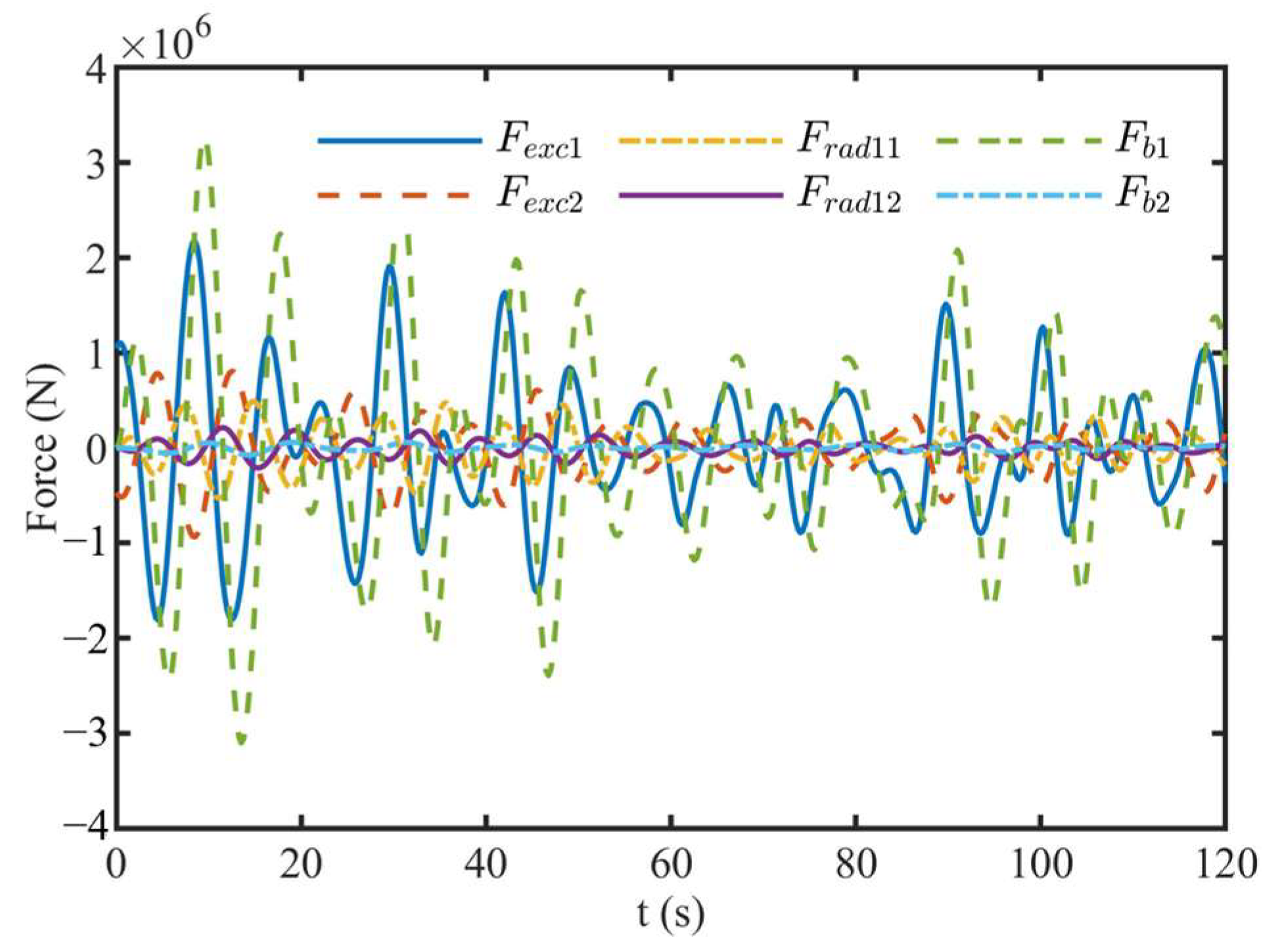
2.2. Hydrodynamic Force

The regular wave excitation force can be represented as follows:
F e x c ( t ) = [ H 2 F e x c ( ω ) e i ω t ]
where denotes the real part of the formula; H is the wave height; and F e x c ( ω ) is the frequency-dependent complex amplitude of the wave excitation force. The dependence of F e x c ( ω ) on the wave direction is neglected, considering the symmetry of the WEC device.
The irregular wave excitation force can be calculated as the superposition of regular wave excitation across all wave frequencies, as follows:
F e x c ( t ) = [ j = 1 N A j F e x c ( ω j ) e i ( ω j t + ϕ j ) ]
where Aj is the wave amplitude at angular frequency ω j , which can be obtained from the wave spectrum; ϕ j is the randomized phase angle at angular frequency ω j , and N is the number of frequency bands selected to discretize the wave spectrum. The Pierson–Moskowitz (PM) spectrum was chosen to describe incident waves in this paper.
S P M ( f ) = H s 2 4 ( 1.057 f p ) 4   f 5 exp [ 5 4 ( f p f ) 4 ]
A j = H j 2 = 2 S ( ω j ) d ω j
where f is the frequency of the PM spectrum; Hs is the significant wave height; fp is the peak frequency; and j is the frequency interval.
The radiation force can be represented as follows [23]:
F r a d i j ( t ) = μ i j x ¨ j 0 t K r i j ( t τ ) x ˙ j ( τ ) d τ
where μij is the added mass at infinite frequency and Krij is the radiation impulse response function. To improve the computing efficiency, a state-space approximation of the convolution term in Equation (6) is needed. It is constructed as follows:
q ˙ = A r q + B r x ˙ 0 t K r ( t τ ) x ˙ d τ = C r q + D r x ˙
where Ar is the system matrix, the dimension of which depends on the accuracy of approximation representation; Br is the input matrix; Cr is the output matrix; Dr is the feedthrough matrix, which is assumed to be zero to maintain the causality of the system and will be omitted in the following equations; and q and q ˙ are the system state and its derivative, respectively. The system input is the heave speed of the corresponding body. Figure 2 shows the impulse response functions and their state-space realizations. The approximate accuracies of all state-space realizations are above 95%. The dimensions of all system matrices are 2 × 2 .
The net buoyancy restoring force can be represented as follows:
F b = ρ g S x = K H x
where ρ is the seawater density; g is the gravity acceleration; S is the water plane area of the body; and KH is the hydrostatic stiffness coefficient.

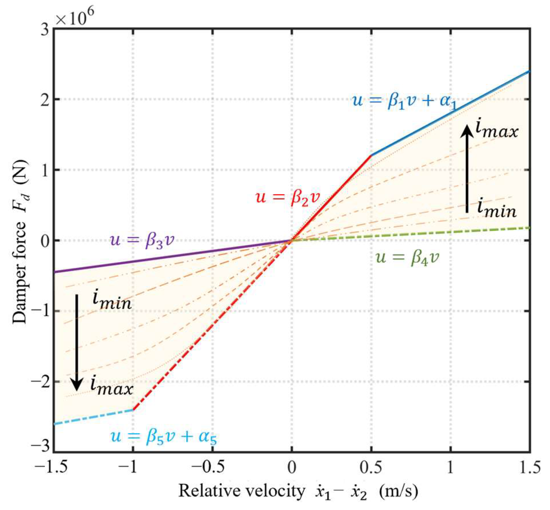
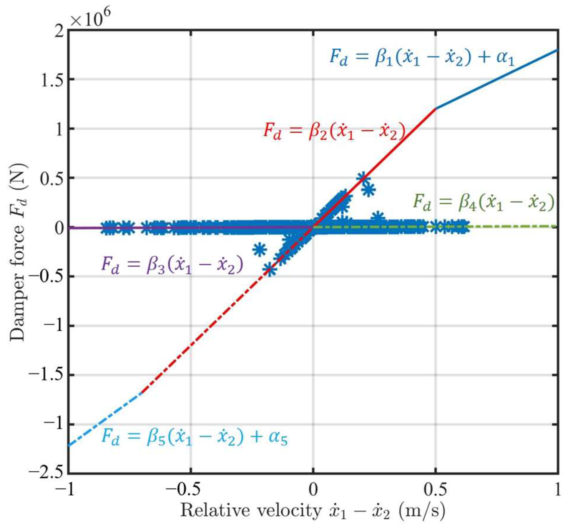
2.3. Power Take-Off Force
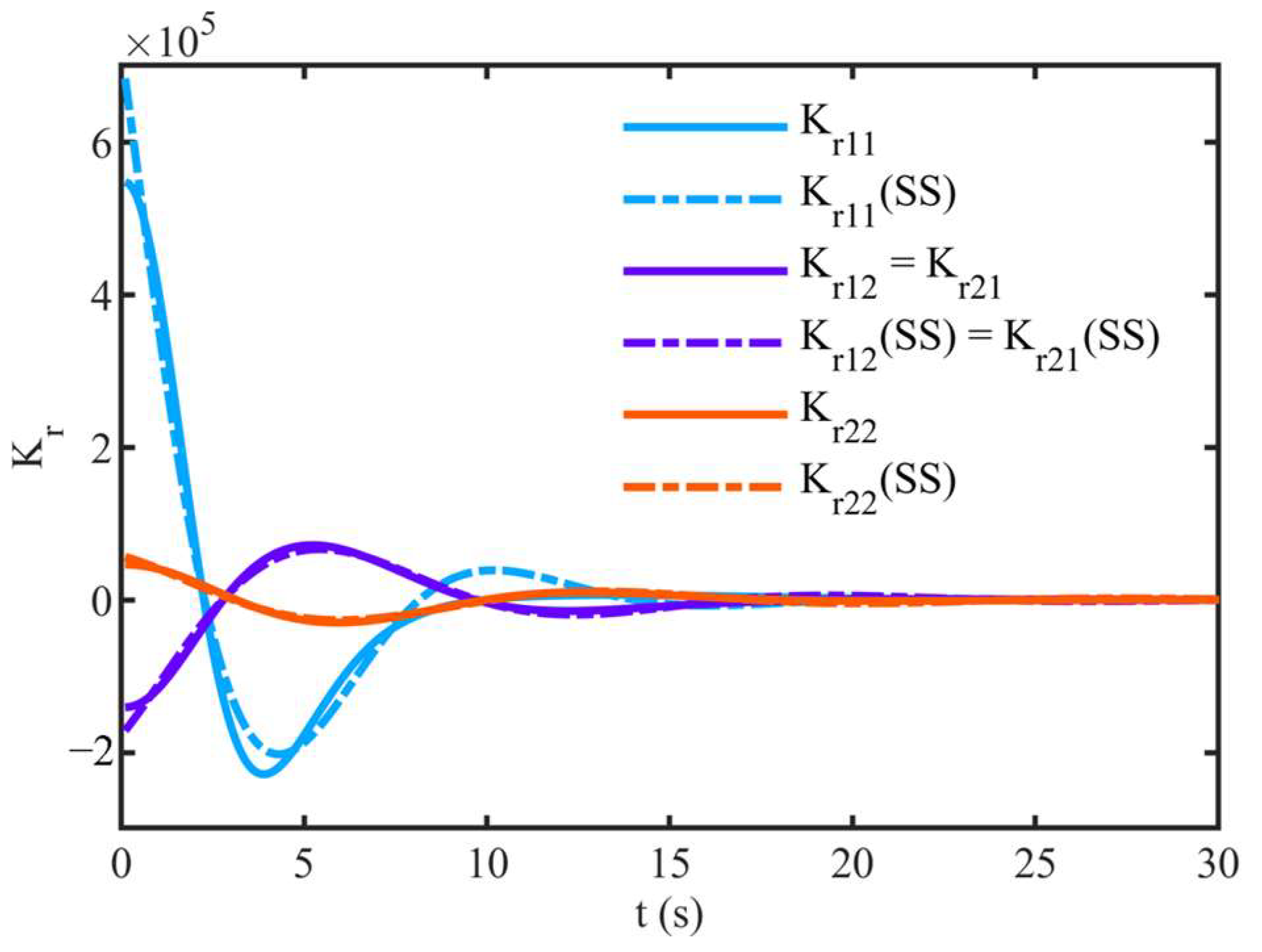
The transmission of the PTO system consists of three main parts, the translation of linear motion to rotational motion, rotation speed amplification, and electricity generation. The dynamics of the ballscrew can be considered as follows:
ω = 2 π x ˙ 1 x ˙ 2 L
where ω is the ballscrew angular speed, that is, the input angular speed of the gearbox; x ˙ 1 x ˙ 2 is the relative heave speed between the float and reaction section; and L is the ballscrew lead. The relation between PTO force and the input moment of the gearbox can be described as follows:
M i = F p t o 2 π L
where Mi is the input moment of the gearbox, and the transmission ratio of the gearbox is denoted as ng. The angular speed and input moment of the generator are calculated as follows:
ω g = n g ω M g = 1 n g M i
where ωg is the angular speed of the generator, and Mg is the input shaft moment of the generator, which is the sum of the electric torque load and the torque induced by the inertia of the generator.
M g = M r + I g ω ˙ g
where Mr is the electric moment induced by the current in the energy harvesting circuit, and Ig is the moment of inertia of the generator.
M r = k t i = k t V R i + R o = k t k e R i + R o ω g
where kt is the torque constant of the generator; i is the output current of the generator; V is the output voltage of the generator; Ri is the internal resistance (motor armature resistance) in the circuit; and Ro is the external resistance (passive load) in the circuit [24,25,26].
Substituting Equations (11)–(13) into Equation (10), the PTO force can be calculated as follows.
n g 2 I g 4 π 2 L 2 ( x ¨ 1 x ¨ 2 ) + 4 π 2 n g 2 k t k e L 2 ( R i + R o ) ( x ˙ 1 x ˙ 2 ) = F p t o
The PTO mechanism can be represented as a linear mass-spring-damper system, where the PTO force is given by the following equation.
F p t o = m p t o ( x ¨ 1 x ¨ 2 ) c p t o ( x ˙ 1 x ˙ 2 ) k p t o ( x 1 x 2 )
where mpto is the mass of the PTO system; cpto is the damping of the PTO system; and kpto is the stiffness of the PTO system. By putting together Equations (14) and (15), it can be deduced as follows.
{ m p t o = n g 2 I g 4 π 2 L 2 c p t o = 4 π 2 n g 2 k t k e L 2 ( R i + R o ) k p t o = 0

2.4. Control Force

In the proposed controller, the control force changes with the variable damping, and the damper force can be represented as follows:
F u = β ( x ˙ 1 x ˙ 2 )
where β is the controllable damping coefficient. Variable damping can be obtained via an electrohydraulic damper, whereby the concept of which is depicted in Figure 3.
Compared to the classical passive hydraulic damper, the electrohydraulic damper comprises electronic valves instead of passive valves. The required damping coefficient can be achieved by adjusting the opening aperture of electronic valves appropriately, controlled by the current i of the servo mechanisms. The energy consumed in obtaining an appropriate damping coefficient is relatively small or negligible. A typical force–current map for an electrohydraulic damper is shown in Figure 4. It should be noted that the positive direction of damper force Fd is opposite to that of the control force F u , i.e., Fd = −Fu.
It can be seen that the damper force non-linearly depends on the relative velocity between rod, cylinder, and current, and is constrained within a shadow-bounded region consisting of five straight lines.
{ u = β 1 v + α 1 u = β 2 v u = β 3 v u = β 4 v u = β 5 v + α 5
The required control current for driving the variable damper system is based on calculated control force Fu and relative velocity x ˙ 1 x ˙ 2 at each time, which can be described as a non-linear inverse function of the damper force, as follows:
{ F d = f ( i , x ˙ 1 x ˙ 2 ) i = f 1 ( F d , x ˙ 1 x ˙ 2 )
The detailed function can be obtained experimentally based on a numerical model, such as a polynomial model [27]. In this study, we focus more on the design of the control strategy, and so the primitive function and inverse function are assumed to be known.

2.5. State-Space Model

To control the WEC device via advanced control strategies, a discrete state-space representation for the WEC system is necessary. The state-space formulation of the convolution integral term in radiation force representation for the two-body WEC system was constructed, which can be formulated as follows.
[ q ˙ 11 q ˙ 12 q ˙ 21 q ˙ 22 ] q ˙ = [ A r 11 0 0 0 0 A r 21 0 0 0 0 A r 21 0 0 0 0 A r 22 ] A r [ q 11 q 12 q 21 q 22 ] q + [ B r 11 0 0 B r 12 B r 21 0 0 B r 22 ] B r [ x ˙ 1 x ˙ 2 ] x ˙ [ F r a d 1 c F r a d 2 c ] = [ C r 11 C r 12 0 0 0 0 C r 21 C r 22 ] C r q
where F r a d 1 c and F r a d 2 c are the radiation forces (convolution integral term) loading in the float and reaction section, respectively. q i j , i , j { 1 , 2 } is the system state of the state-space realization for the convolution term of radiation forces F r a d i j .
F r a d 1 c = 0 t K r 11 ( t τ ) x ˙ d τ + 0 t K r 12 ( t τ ) x ˙ d τ F r a d 2 c = 0 t K r 21 ( t τ ) x ˙ d τ + 0 t K r 22 ( t τ ) x ˙ d τ
Substituting Equations (6), (8), (15) and (21) into Equation (1), the dynamic equation can be restated as follows:
M x ¨ = [ F r a d 1 c F r a d 2 c ] c p t o N x ˙ ( K H + k p t o N ) x + [ F e x c 1 F e x c 2 ] F e x c + [ F u F u ]
where,
M = [ μ 11 μ 12 μ 21 μ 22 ] + [ m 1 0 0 m 2 ] + m p t o N K H = [ K H 1 0 0 K H 2 ] ,   N = [ 1 1 1 1 ]
It can be assumed that the state vector is chosen as p = [ x 1 x 2 x ˙ 1 x ˙ 2 q T ] T ; then, the continuous state-space model can be obtained by substituting Equation (20) into Equation (22).
p ˙ = A p + B e F e x c + B u F u A = [ 0 I 0 M 1 ( c p t o N + K H ) M 1 ( c p t o N ) M 1 C r 0 B r A r ] B e = [ 0 M 1 0 ] ,   B u = [ 1 1 ] B e
Finally, the state-space model is discretized by zero-order hold (ZOH) with sampling time Ts (Ts = 0.25 s in this study) to obtain the discrete state-space representation for the WEC system.
p ( k + 1 ) = A d p ( k ) + B d e F e x c ( k ) + B d u F u ( k ) = A d p ( k ) + B d e F e x c ( k ) B d u F d ( k )
where,
A d = e A T s B d e = 0 T s e A T s B e d t B d u = 0 T s e A T s B u d t

3. Hybrid MPC Problem Formulation

3.1. Hybrid Dynamical Model

As mentioned in Section 2.4, the damper force must lay in the shadow-bounded region in the force–current map. This non-linear constraint can be translated into a set of thresholds and logic conditions by introducing a binary variable δv.
[ δ v = 1 ] [ x ˙ 1 x ˙ 2 0 ]
where the connective “ ” means “if and only if”. This mixed logic continuous relation can be translated into linear constraints involving the logical variable δv.
x ˙ 1 x ˙ 2 v l ( 1 δ v ) x ˙ 1 x ˙ 2 ε + ( v u ε ) δ v
where vl and vu are lower and upper bounds to the function x ˙ 1 x ˙ 2 , respectively; ε > 0 is a small tolerance, typically the machine precision.
The constraints for damper force can be written in a more detailed form, as follows [28]:
z 1 = { β 2 ( x ˙ 1 x ˙ 2 ) + α 2 F d ,   if   x ˙ 1 x ˙ 2 0 F d β 2 ( x ˙ 1 x ˙ 2 ) α 2 ,   otherwise z 2 = { β 1 ( x ˙ 1 x ˙ 2 ) + α 1 F d ,   if   x ˙ 1 x ˙ 2 0 F d β 5 ( x ˙ 1 x ˙ 2 ) α 5 ,   otherwise z 3 = { F d β 4 ( x ˙ 1 x ˙ 2 ) α 4 ,   if   x ˙ 1 x ˙ 2 0 β 3 ( x ˙ 1 x ˙ 2 ) + α 3 F d ,   otherwise
where z1, z2, and z3  are continuous auxiliary variables, which are imposed constraints.
z 1 , z 2 ,   z 3 0
A generic if–then–else construct of the form is as follows:
IF   δ   THEN   z = a 1 x + b 1 u + f 1         ELSE   z = a 2 x + b 2 u + f 2
where δ { 0 , 1 } , z , x n , u m , a1, a2, b1, b2, f1, and f2 are constants with approximate dimensions, which can be translated into integer linear inequalities of the form.
( f 2 F 1 ) δ + z a 2 x + b 2 u + c 2 ( f 1 F 2 ) δ z a 2 x b 2 u c 2 ( f 1 F 2 ) ( 1 δ ) + z a 1 x + b 1 u + c 1 ( f 2 F 1 ) ( 1 δ ) z   a 1 x b 1 u c 1
where fi and Fi are lower and upper bounds to a i x + b i u + c i , i { 1 , 2 } . Each if–then–else equation in Equation (29) can be translated into four linear inequality constraints.
Relative displacement and speed constraints are other issues that need to be considered for WEC devices.
x m i n x 1 x 2 x m a x x ˙ m i n x ˙ 1 x ˙ 2 x ˙ m a x
where xmin and xmax are the maximum and minimum relative displacement that the system can achieve. x ˙ m i n and x ˙ m a x are the maximum and minimum relative velocity. The relative displacement constraint represents a finite stroke limit of the WEC device, which prevents the PTO hardware and the surrounding structure from impulsive loads [29].
The discrete-time dynamic system (25) with constraints (28), (30), (32) and (33) can be modeled as a mixed logical dynamical (MLD) system in HYSDEL (a high-level modeling language for the specification of hybrid systems) [30]. It should be noted that the relative velocity constraints are only used to guarantee the operation of HYSDEL.
p ( k + 1 ) = A d p ( k ) B d u F d ( k ) + B d δ δ v ( k ) + B d z z ( k ) + B d e F e x c E 2 δ v ( k ) + E 3 z ( k ) E 1 F d ( k ) + E 4 p ( k ) + E 5
In this paper, p 12 is the state vector; F d is the control input; δ v { 0 , 1 } is the logic variable; z 3 is the vector of continuous auxiliary variables; F e x c is the wave excitation force vector, which can be seen as the disturbances of the state update equation; Ad, Bdu, and Bde are the discrete system matrices from the original state-space Equation (25); B and Bdz are the zero matrices in our case; and E2, E3, E1, E4, and E5 are matrices of suitable dimensions.

3.2. Hybrid MPC Problem

The objective of control in WEC is to maximize the power generation over the prediction horizon, which can be described as a receding horizon optimal problem. The objective function can be written as follows:
max u   i = k k + N p c p t o [ x ˙ 1 ( i ) x ˙ 2 ( i ) ] 2
For convenience, the objective function can be written as a cost function (and thus is a minimization problem) of the form.
min u   i = k k + N p c p t o p T ( i ) Q p ( i )
where Np is the optimization horizon length.
Q = N T N N = [ 0 0 1 1 0 T ]
Based on the hybrid logic constraints, the hybrid MPC can be formulated as follows:
min u i = k k + N p c p t o p T ( i ) Q p ( i ) s . t . { p ( k + 1 ) = A d p ( k ) B d u F d ( k ) + B d δ δ v ( k ) + B d z z ( k ) + B d e F e x c E 2 δ v ( k ) + E 3 z ( k ) E 1 F d ( k ) + E 4 p ( k ) + E 5

4. Numerical Investigation and Result

4.1. Case Study

In this section, a case of hybrid MPC for the two-body WEC is simulated. The key physical specifications for the WEC system are given in Table 1 (the parameters are from Reference Model 3 [31]). The seawater density ρ takes the value of 1025 kg/m3 and the gravity acceleration takes the value of 9.81 m/s2.
Under the assumption that the future wave excitation force is known, the hybrid MPC was applied in the two-body WEC with Tp = 8 s and Hs = 2.5 m wave input. The spectrum and corresponding wave elevation are shown in Figure 5. The prediction horizon Np = 32 (8 s). The entire simulation time is 120 s.
The same PTO mechanism was used for all simulations. The parameters of the PTO system can be found in Table 2. The boundary coefficients of damper force are shown in Table 3, and the relative displacement and velocity constraints are summarized in Table 4.
The hydrodynamic coefficients used in this study were provided by AQWA 2022. The wave excitation forces, radiation forces, and buoyancy restoring forces under no control and hybrid MPC are shown in Figure 6 and Figure 7, respectively. It should be noted that the wave excitation forces are the same under uncontrolled and hybrid MPC, due to the limitations of the BEM software.
Figure 8 shows the time history curves of the relative displacement and velocity of the WEC. It can be seen that the motion response of the two-body WEC is dramatically oscillatory. The result of the oscillatory period will be neglected in the following sections. Moreover, we can see that the relative displacement and velocity oscillate around zero and do not exceed the relative displacement and velocity constraints.
Figure 9 shows the damper force corresponding to the relative velocity. All damper forces are constrained to the bounded region. It can be found that maximum damping is seldom used and only at low relative velocities. The possible reason is that the latching happens at the instant when the device velocity becomes zero or very small. At zero or small relative velocity instants, the hybrid MPC has the same function with latching control, i.e., locking the PTO for certain time intervals to achieve the optimum phase. Furthermore, it can be found that most of the damper force lies on the constraint boundary. So, the boundary coefficients of the damper force significantly affect the hybrid MPC, which will be discussed in the next section.

4.2. Control Force Constraint

In Section 2.4, the method of obtaining variable damping was discussed. It must be noted that the opening aperture of the electronic valves is not unlimited due to hardware size limitations, which also leads to the damper coefficient not being infinitely small, i.e., the parameters β3 and β4 cannot be zero. To investigate the effect of parameters β3 and β4 on the performance of hybrid MPC, we assumed that β3 is equal to β4 and the wave excitation force prediction is exact. The average power P ¯ over the horizon length Ns in terms of the number of samples can be calculated as follows:
P ¯ = 1 N s t = 1 N s c p t o [ x ˙ 1 ( t ) x ˙ 2 ( t ) ] 2
The average generated power and power improvement percentage relative to uncontrolled power generation under different parameters β3 and β4 are listed in Table 5. The simulated result is under the wave condition of Tp = 8 s and Hs = 2.5 m, and the prediction horizon Np is 32 (8 s). The average generated power of uncontrolled WEC is 76.808 kW.
It can be seen that the average generated power of hybrid MPC with zero β3 and β4 is maximum. The power generation gradually decreases as the coefficients β3 and β4 increase, and there is a critical value βc (104 < βc < 105); the power generation will be less than the case of no control when the boundary coefficients are greater than this value. The variable damper is placed in parallel with the PTO so that the captured energy by WEC is converted into PTO energy and hydraulic energy, with the former being subsequently converted into available electricity and the latter being converted into thermal energy dissipation. The energy converted via internal damping can be improved by adjusting the damper in a small interval of damping coefficient when less energy is dissipated by the variable damper, and most energy is converted into electrical energy. However, a too-large damping coefficient will result in too much energy being dissipated by the damper, reducing the improved performance of variable damping. In reality, a minor boundary coefficient of the electrohydraulic damper is challenging to obtain due to the limitations of the openings, and so a larger boundary coefficient (β3 = β4 = 1 × 10⁴ Ns/m) was applied in subsequent studies.

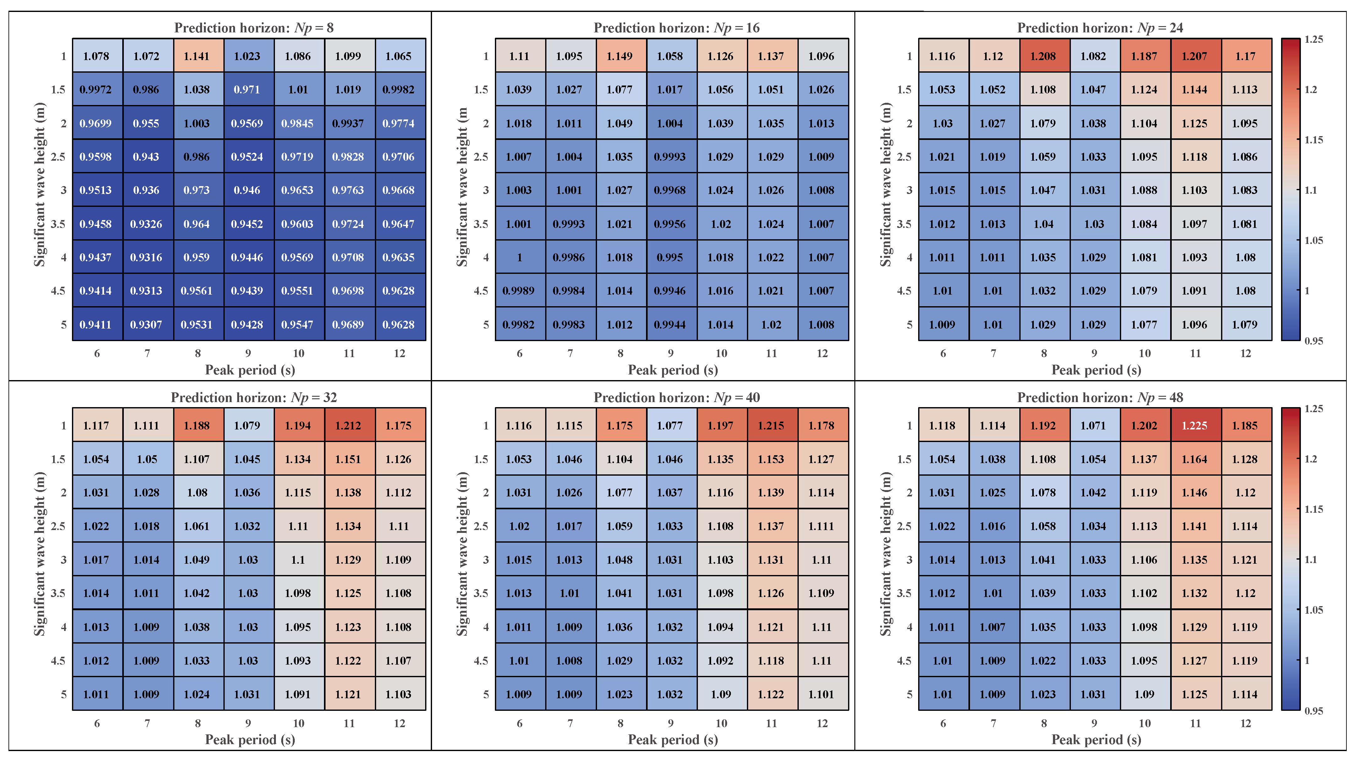
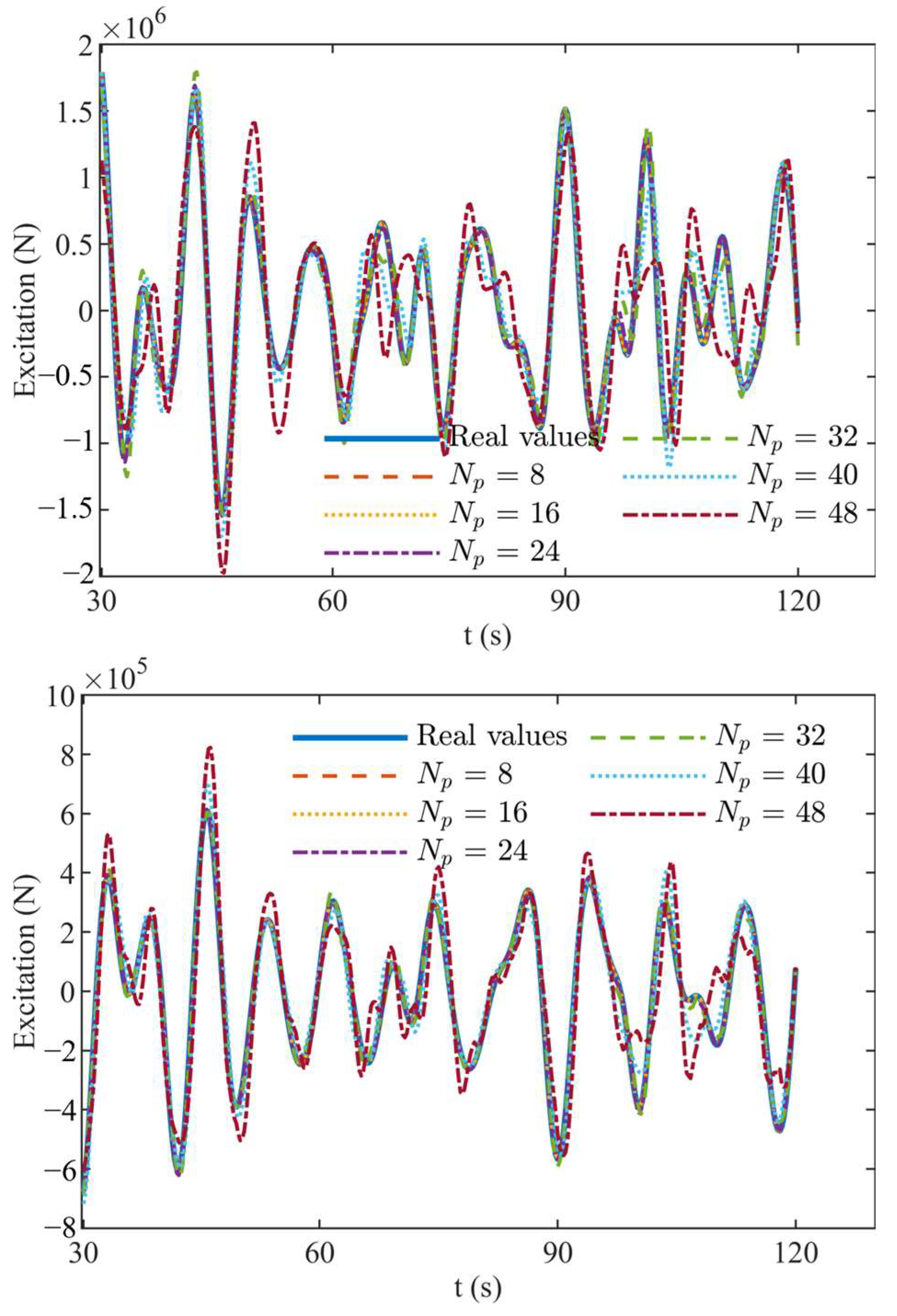
4.3. Prediction Horizon and Wave Condition

The power ratio heatmaps of different prediction horizons under various wave conditions are shown in Figure A1. Each wave state has the same random wave phase. The simulation results are the ratios of generation power of the hybrid MPC system to uncontrolled output power in each wave state. The Hs and Tp of irregular waves range from 1~5 m to 6~12 s, respectively, which cover most of the possible sea conditions.
As can be seen from Figure A1, the hybrid MPC has a negative effect on power generation in a large portion of the wave conditions when the prediction horizon is short Np ≤ 16 (4 s). With the increase in prediction horizon Np ≥ 32 (8 s), the power improvement percentage tends to be steady, and the effect of increasing the prediction horizon on power stops being apparent. This indicates that the proposed hybrid MPC has a high requirement for the prediction capability of wave excitation force. However, the simulations here assume that the future wave excitation force is precisely known, which is different from the actual situation. The prediction of the wave excitation force is subject to some error as the prediction horizon increases, which also affects the performance of the hybrid MPC. The effects of the prediction error of wave excitation force will be discussed in the following section.
In the simulations, the maximum power improvement is 22.5% relative to the uncontrolled system (Np = 48, Tp = 11 s, Hs = 1 m). It should be noted that the simulations all assume a large boundary coefficient (β3 = β4 = 1 × 10⁴ Ns/m). If the smaller coefficient can be selected, the power generation by the hybrid MPC system will improve.

4.4. Prediction Error

As mentioned in the above sections, the discussions assumed that future wave excitation force is precisely known but needs to be predicted in reality. Therefore, it is essential to discuss the impact of prediction error on the performance of the hybrid MPC. Two 60th-order (15 s) auto-regressive (AR) models were selected to predict the wave excitation force of the float and reaction section, respectively. The accuracy of the predicted values was described using a goodness of fit (GoF) metric, which is defined as follows.
GoF = ( 1 k = 1 N p ( f k f ^ k ) 2 k = 1 N p f k 2 ) × 100
where f k is the real value and f ^ k is the predicted value.
The time history curves of real and predicted wave excitation for the float and reaction section are shown in Figure 10, and their GoF values are summarized in Table 6 (Hs = 2.5 m, Tp = 8 s). The GoF1 and GoF2 are the prediction accuracy for the float and reaction section, respectively. It can be seen that the GoF is large within a short prediction horizon, and the prediction error gradually increases as the prediction horizon increases. The AR model has sufficient capacity to predict future wave excitation force when the prediction horizon is less than 6 s, with over 94% GoF for the float and reaction section. However, the prediction accuracy decays rapidly when the prediction horizon exceeds 8 s. Another noteworthy phenomenon is that the prediction accuracy for the reaction section is greater than that of the float for the same prediction horizon. The possible reason is that the motion response of the reaction plate is smooth and tends to be more of a stationary time series.
In Table 6, Power1 and Power2 are the generation power under the exact prediction and the generation power under the AR prediction, respectively. It can be seen that the power generation under the inaccurate prediction is better than that under exact prediction within a short horizon (Np ≤ 16). This indicates that the solution of the hybrid MPC is suboptimal, and a more accurate solution method needs to be investigated. As the prediction error increases, the degree of power degradation for non-accurate prediction tends to be extended. In summary, the determination of the prediction horizon is essential, which has a systemic impact on MPC.

5. Conclusions

In this paper, a variable damper was proposed for controlling the dynamics of a two-body WEC with mechanically driven PTO, which introduces logic constraints in the system. A hybrid MPC formulation involving logic variables and continuous variables was constructed to maximize power extraction with the consideration of model limitations. The influence and function of parameters in the proposed method on the two-body WEC have been numerically studied.
The damper valve opening aperture, which imposes a limit on the control force, has an impact on the performance of the proposed hybrid MPC. The larger the maximum opening aperture that can be achieved by the damper valve, the better the performance of the hybrid MPC that could be obtained. The proposed hybrid MPC has a high requirement for the prediction capability of wave excitation force and has the best performance under long Tp and small Hs wave conditions. The prediction horizon has a systemic impact on hybrid MPC performance. A long prediction horizon can improve generation power compared to no-control devices, although a large prediction error accompanies this.
Moreover, despite the realistic feasibility of the proposed controller, there are still some problems that limit the use of hybrid MPC, such as computational efficiency and excitation force prediction accuracy. These can be the subject of future work.

Author Contributions

Conceptualization, Methodology, Writing, and Editing, Z.Z.; Investigation and Validation, J.Q.; Investigation and Validation, D.W.; Reviewing, S.H.; Reviewing and Supervision, Y.L.; Reviewing and Editing, G.X. All authors have read and agreed to the published version of the manuscript.

Funding

The research was supported by the National Natural Science Foundation of China (52171265, 52001186) and Natural Science Foundation of Shandong Province (ZR2020QE292, ZR2021ZD23).

Institutional Review Board Statement

Not applicable.

Informed Consent Statement

Not applicable.

Data Availability Statement

Not applicable.

Conflicts of Interest

The authors declare no conflict of interest.

Appendix A

Figure A1. Average output power ratio of different prediction horizons under irregular wave conditions.
Jmse 11 01618 g0a1

References

  1. Ringwood, J.V.; Bacelli, G.; Fusco, F. Energy-Maximizing Control of Wave-Energy Converters: The Development of Control System Technology to Optimize Their Operation. IEEE Control Syst. Mag. 2014, 34, 30–55. [Google Scholar] [CrossRef]
  2. Lehmann, M.; Karimpour, F.; Goudey, C.A.; Jacobson, P.T.; Alam, M.-R. Ocean Wave Energy in the United States: Current Status and Future Perspectives. Renew. Sustain. Energy Rev. 2017, 74, 1300–1313. [Google Scholar] [CrossRef]
  3. Montoya Andrade, D.-E.A.; de la Villa Jaen, A.; Garcia Santana, A. Improvements in the Reactive Control and Latching Control Strategies Under Maximum Excursion Constraints Using Short-Time Forecast. IEEE Trans. Sustain. Energy 2016, 7, 427–435. [Google Scholar] [CrossRef]
  4. Falnes, J.; Kurniawan, A. Ocean Waves and Oscillating Systems: Linear Interactions Including Wave-Energy Extraction, 2nd ed.; Cambridge University Press: Cambridge, UK, 2020; ISBN 978-1-108-67481-2. [Google Scholar]
  5. Budal, K.; Falnes, J. Interacting Point Absorbers with Controlled Motion. In Power from Sea Waves; Academic Press: Cambridge, MA, USA, 1980; pp. 381–399. [Google Scholar]
  6. Teillant, B.; Gilloteaux, J.C.; Ringwood, J.V. Optimal Damping Profile for a Heaving Buoy Wave Energy Converter. IFAC Proc. Vol. 2010, 43, 360–365. [Google Scholar] [CrossRef]
  7. Feng, Z.; Kerrigan, E.C. Declutching Control of Wave Energy Converters Using Derivative-Free Optimization. IFAC Proc. Vol. 2014, 47, 7647–7652. [Google Scholar] [CrossRef]
  8. Feng, Z.; Kerrigan, E.C. Latching-Declutching Control of Wave Energy Converters Using Derivative-Free Optimization. IEEE Trans. Sustain. Energy 2015, 6, 773–780. [Google Scholar] [CrossRef]
  9. Wang, Z.; Luan, F.; Wang, N. An Improved Model Predictive Control Method for Wave Energy Converter with Sliding Mode Control. Ocean Eng. 2021, 240, 109881. [Google Scholar] [CrossRef]
  10. Li, L.; Gao, Y.; Ning, D.Z.; Yuan, Z.M. Development of a Constraint Non-Causal Wave Energy Control Algorithm Based on Artificial Intelligence. Renew. Sustain. Energy Rev. 2021, 138, 110519. [Google Scholar] [CrossRef]
  11. Lin, Z.; Huang, X.; Xiao, X. A Novel Model Predictive Control Formulation for Wave Energy Converters Based on the Reactive Rollout Method. IEEE Trans. Sustain. Energy 2022, 13, 491–500. [Google Scholar] [CrossRef]
  12. Sergiienko, N.Y.; Cocho, M.; Cazzolato, B.S.; Pichard, A. Effect of a Model Predictive Control on the Design of a Power Take-off System for Wave Energy Converters. Appl. Ocean Res. 2021, 115, 102836. [Google Scholar] [CrossRef]
  13. Faedo, N.; Olaya, S.; Ringwood, J.V. Optimal Control, MPC and MPC-like Algorithms for Wave Energy Systems: An Overview. IFAC J. Syst. Control 2017, 1, 37–56. [Google Scholar] [CrossRef]
  14. Li, X.; Chen, C.; Li, Q.; Xu, L.; Liang, C.; Ngo, K.; Parker, R.G.; Zuo, L. A Compact Mechanical Power Take-off for Wave Energy Converters: Design, Analysis, and Test Verification. Appl. Energy 2020, 278, 115459. [Google Scholar] [CrossRef]
  15. Jusoh, M.A.; Ibrahim, M.Z.; Daud, M.Z.; Albani, A.; Mohd Yusop, Z. Hydraulic Power Take-Off Concepts for Wave Energy Conversion System: A Review. Energies 2019, 12, 4510. [Google Scholar] [CrossRef]
  16. Falcão, A.F.O.; Henriques, J.C.C.; Gato, L.M.C. Self-Rectifying Air Turbines for Wave Energy Conversion: A Comparative Analysis. Renew. Sustain. Energy Rev. 2018, 91, 1231–1241. [Google Scholar] [CrossRef]
  17. Penalba, M.; Ringwood, J.V. A Review of Wave-to-Wire Models for Wave Energy Converters. Energies 2016, 9, 506. [Google Scholar] [CrossRef]
  18. Li, X.; Liang, C.; Chen, C.-A.; Xiong, Q.; Parker, R.G.; Zuo, L. Optimum Power Analysis of a Self-Reactive Wave Energy Point Absorber with Mechanically-Driven Power Take-Offs. Energy 2020, 195, 116927. [Google Scholar] [CrossRef]
  19. Martin, D.; Li, X.; Chen, C.-A.; Thiagarajan, K.; Ngo, K.; Parker, R.; Zuo, L. Numerical Analysis and Wave Tank Validation on the Optimal Design of a Two-Body Wave Energy Converter. Renew. Energy 2020, 145, 632–641. [Google Scholar] [CrossRef]
  20. Yang, L.; Huang, J.; Congpuong, N.; Chen, S.; Mi, J.; Bacelli, G.; Zuo, L. Control Co-Design and Characterization of a Power Takeoff for Wave Energy Conversion Based on Active Mechanical Motion Rectification. IFAC-Pap. 2021, 54, 198–203. [Google Scholar] [CrossRef]
  21. Li, Q.; Li, X.; Mi, J.; Jiang, B.; Chen, S.; Zuo, L. Tunable Wave Energy Converter Using Variable Inertia Flywheel. IEEE Trans. Sustain. Energy 2021, 12, 1265–1274. [Google Scholar] [CrossRef]
  22. Yang, Y.; Chen, P.; Liu, Q. A Wave Energy Harvester Based on Coaxial Mechanical Motion Rectifier and Variable Inertia Flywheel. Appl. Energy 2021, 302, 117528. [Google Scholar] [CrossRef]
  23. Zhong, Q.; Yeung, R.W. Model-Predictive Control Strategy for an Array of Wave-Energy Converters. J. Mar. Sci. Appl. 2019, 18, 26–37. [Google Scholar] [CrossRef]
  24. Liu, Y.; Xu, L.; Zuo, L. Design, Modeling, Lab, and Field Tests of a Mechanical-Motion-Rectifier-Based Energy Harvester Using a Ball-Screw Mechanism. IEEE/ASME Trans. Mechatron. 2017, 22, 1933–1943. [Google Scholar] [CrossRef]
  25. Lin, T.; Pan, Y.; Chen, S.; Zuo, L. Modeling and Field Testing of an Electromagnetic Energy Harvester for Rail Tracks with Anchorless Mounting. Appl. Energy 2018, 213, 219–226. [Google Scholar] [CrossRef]
  26. Li, X.; Chen, C.-A.; Chen, S.; Xiong, Q.; Huang, J.; Lambert, S.; Keller, J.; Parker, R.G.; Zuo, L. Dynamic Characterization and Performance Evaluation of a 10-kW Power Take-off with Mechanical Motion Rectifier for Wave Energy Conversion. Ocean Eng. 2022, 250, 110983. [Google Scholar] [CrossRef]
  27. Qin, Y.; Zhao, F.; Wang, Z.; Gu, L.; Dong, M. Comprehensive Analysis for Influence of Controllable Damper Time Delay on Semi-Active Suspension Control Strategies. J. Vib. Acoust. 2017, 139, 031006. [Google Scholar] [CrossRef]
  28. Borrelli, F.; Bemporad, A.; Morari, M. Predictive Control for Linear and Hybrid Systems; Cambridge University Press: Cambridge, UK, 2017; ISBN 1-108-15829-3. [Google Scholar]
  29. Lao, Y.; Scruggs, J.T.; Karthikeyan, A.; Previsic, M. Discrete-Time Causal Control of a Wave Energy Converter With Finite Stroke in Stochastic Waves. IEEE Trans. Control Syst. Technol. 2022, 30, 1198–1214. [Google Scholar] [CrossRef]
  30. Torrisi, F.D.; Bemporad, A. HYSDEL—A Tool for Generating Computational Hybrid Models for Analysis and Synthesis Problems. IEEE Trans. Contr. Syst. Technol. 2004, 12, 235–249. [Google Scholar] [CrossRef]
  31. Yu, Y.H.; Lawson, M.; Li, Y.; Previsic, M.; Epler, J.; Lou, J. Experimental Wave Tank Test for Reference Model 3 Floating-Point Absorber Wave Energy Converter Project; National Renewable Energy Laboratory (NREL): Golden, CO, USA, 2015.
Figure 1. Overview of the two-body wave energy converter system.
Jmse 11 01618 g001
Figure 2. Impulse response functions and their state-space approximations.
Jmse 11 01618 g002
Figure 3. Schematic representation of an electrohydraulic damper.
Jmse 11 01618 g003
Figure 4. A typical force–current map.
Jmse 11 01618 g004
Figure 5. Wave spectrum and wave elevation.
Jmse 11 01618 g005
Figure 6. The wave excitation force, radiation force, and buoyancy restoring force under no control.
Jmse 11 01618 g006
Figure 7. The wave excitation force, radiation force, and buoyancy restoring force under hybrid MPC.
Jmse 11 01618 g007
Figure 8. The relative displacement and velocity (Tp = 8 s, Hs = 2.5 m).
Jmse 11 01618 g008
Figure 9. Velocity–force response map (Tp = 8 s, Hs = 2.5 m).
Jmse 11 01618 g009
Figure 10. Real and predicted wave excitation for the float (up) and reaction section (down).
Jmse 11 01618 g010
Table 1. Specifications of the WEC model (CoG: center of gravity).
Body Diameter (m)Draft (m)Mass (t)CoG (m)
Float 203727.01−0.72
Reaction sectionSpar630878.30−21.29
Plate30
Table 2. Power take-off parameters.
SymbolQuantityParameter Explanation
ng10gearbox ratio
Ig0.54 kg∙m2generator moment of inertia
L0.1 mballscrew lead
kt2.5 Nm/Agenerator torque constant
ke120 Vs/radgenerator speed constant
Ri2.1 Ωinternal resistance
Ro100 Ωexternal resistance
Table 3. Damper force constraint parameters.
Parameterβ1β2β3β4β5α1α5
Value1.2 × 1062.4 × 1061.0 × 1041.0 × 1041.8 × 1066.0 × 105−4.2 × 10⁵
Table 4. Relative displacement and velocity constraints.
Symbol QuantityParameter Explanation
xmax8 mmaximum relative displacement
xmin−8 mminimum relative displacement
vmin5 m/smaximum relative velocity
vmax−5 m/sminimum relative velocity
Table 5. Average power comparison under different parameters β3 and β4.
β3, β4 (104)Average Power (kW)Power Improvement Percentage (%)
082.2147.4454
0.0182.2067.4349
0.182.1397.3474
181.4696.4718
1075.406−1.4520
5055.483−27.4893
10041.453−45.8251
Table 6. GoF of the AR model and hybrid MPC performance under prediction error.
NpGoF1 (%)GoF2 (%)Power1 (kW)Power2 (kW)Power Improvement
Percentage (%)
899.9999.9975.7377.021.70%
1699.5699.7979.4879.561.00%
2494.3196.6781.3181.06−0.31%
3281.6291.9381.4781.44−0.04%
4067.2878.0681.3480.57−0.95%
4839.5860.0981.2877.50−4.65%
Disclaimer/Publisher’s Note: The statements, opinions and data contained in all publications are solely those of the individual author(s) and contributor(s) and not of MDPI and/or the editor(s). MDPI and/or the editor(s) disclaim responsibility for any injury to people or property resulting from any ideas, methods, instructions or products referred to in the content.

