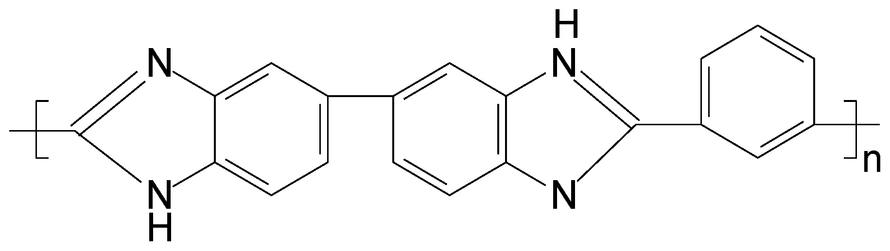
Preparation of Polybenzimidazole Hollow-Fiber Membranes for Reverse Osmosis and Nanofiltration by Changing the Spinning Air Gap

Abstract
:1. Introduction
2. Experimental
2.1. Materials and Reagents
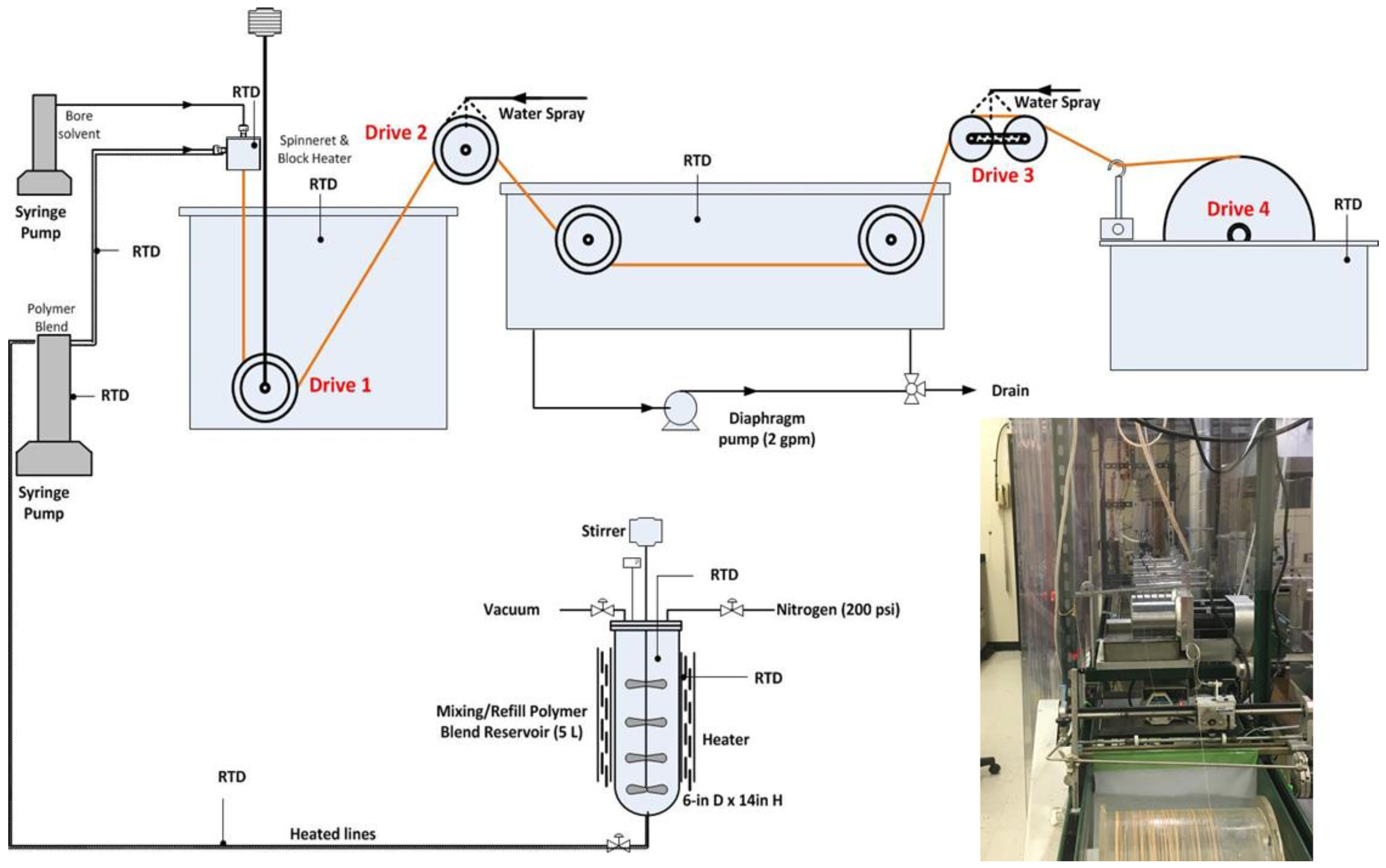
2.2. Fabrication of PBI HF and Preparation of Fiber Module
2.3. Scanning Electron Microscopy (SEM) Measurements
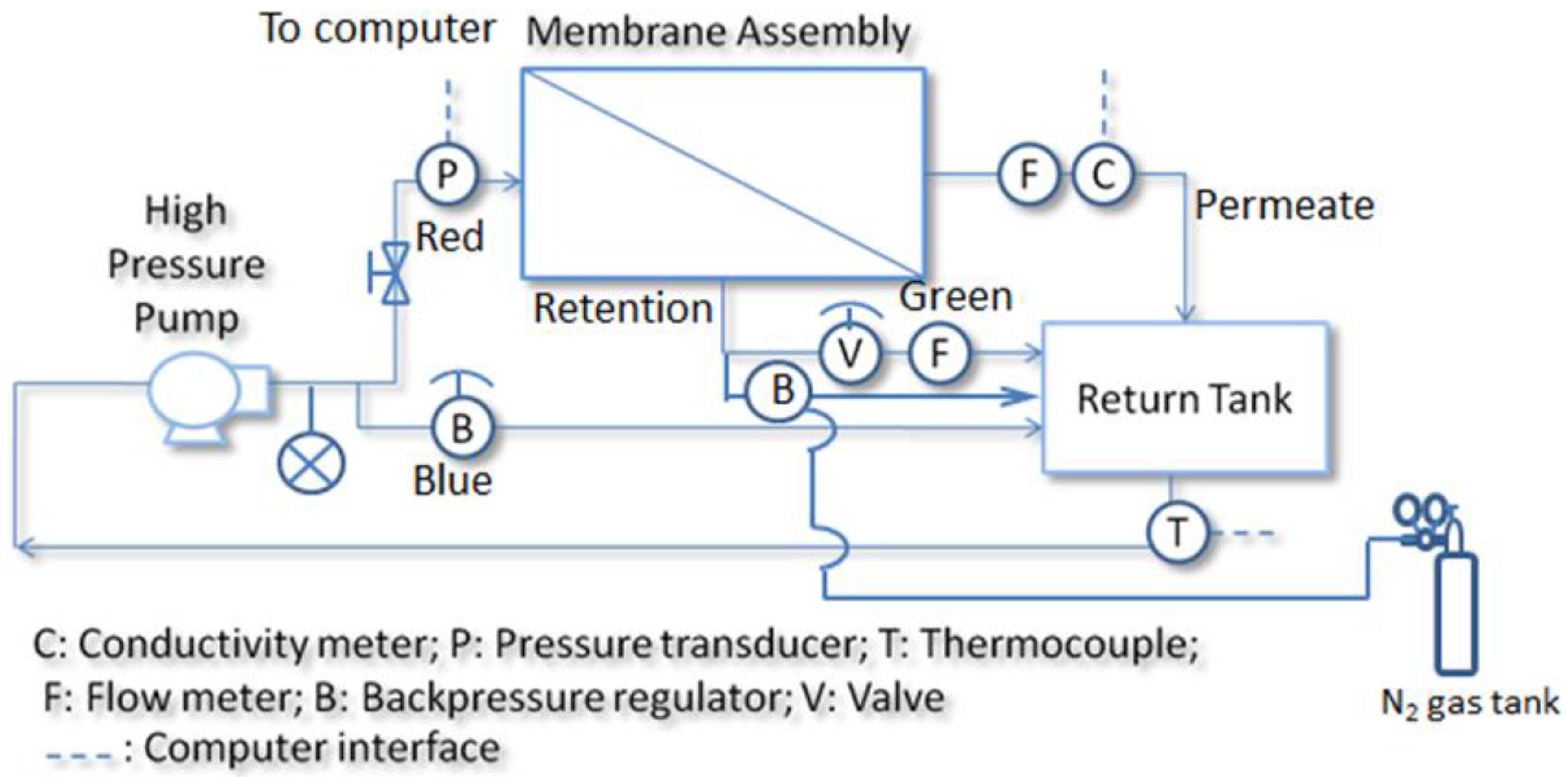
2.4. Desalination Test
3. Results and Discussions
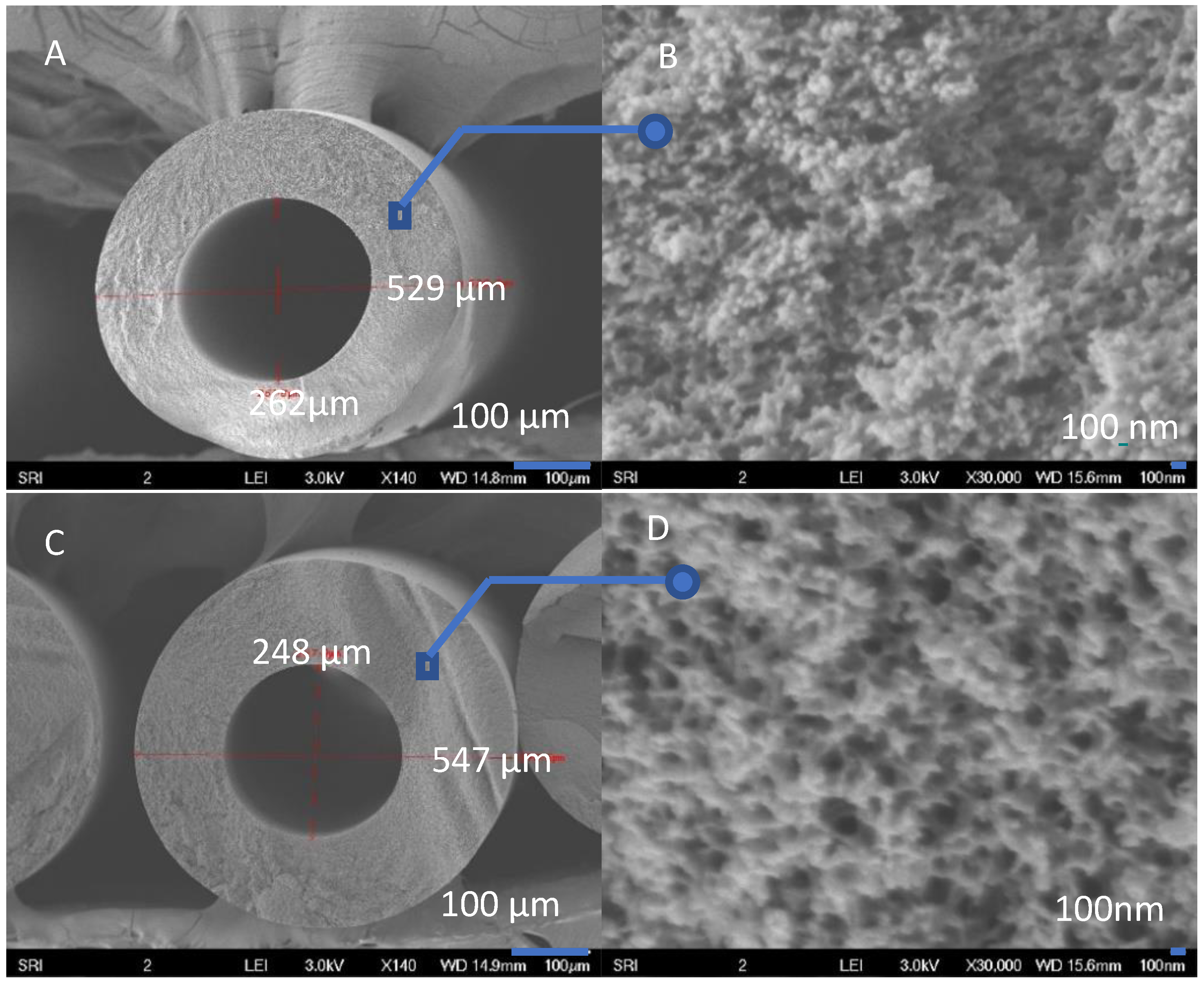
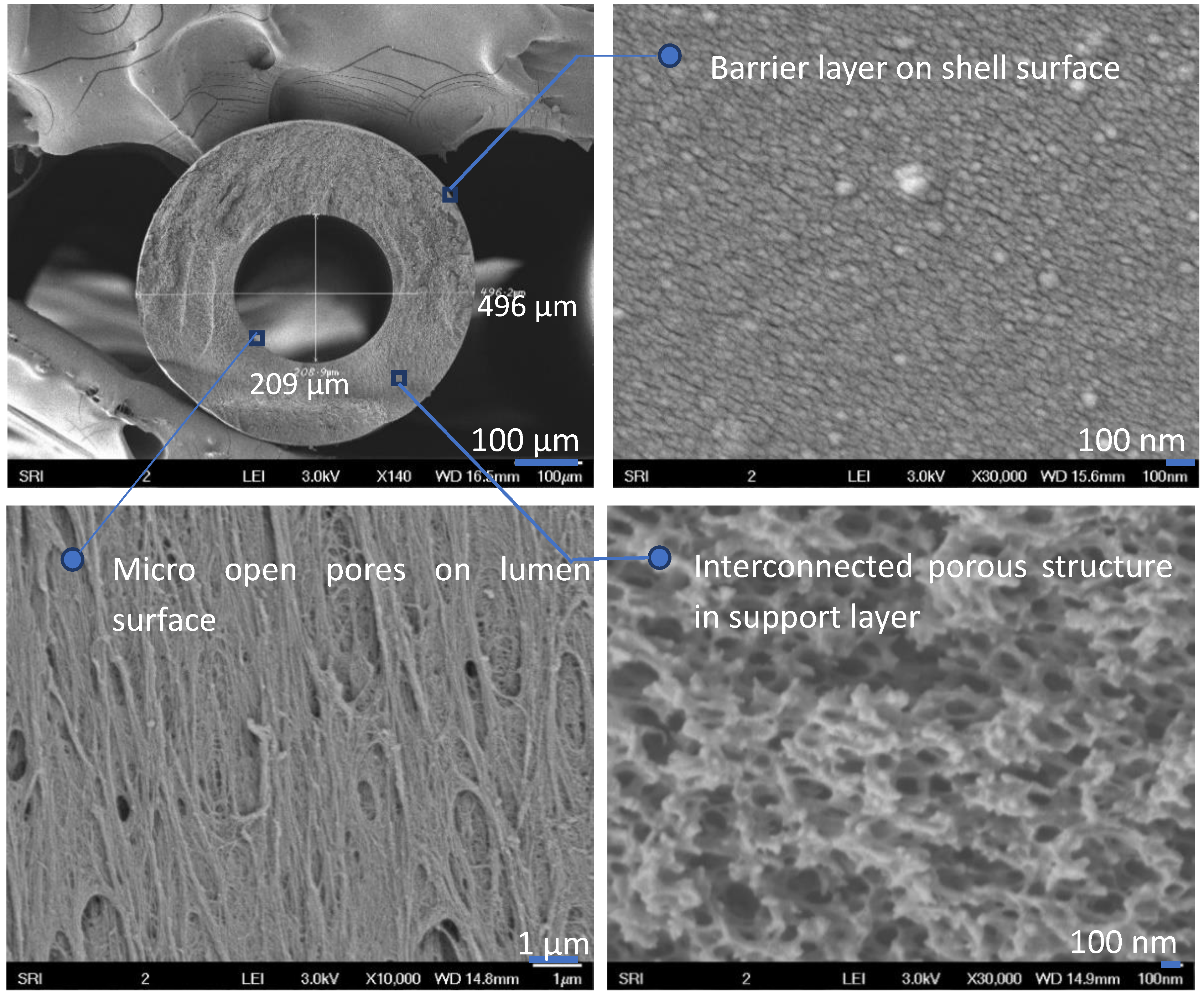
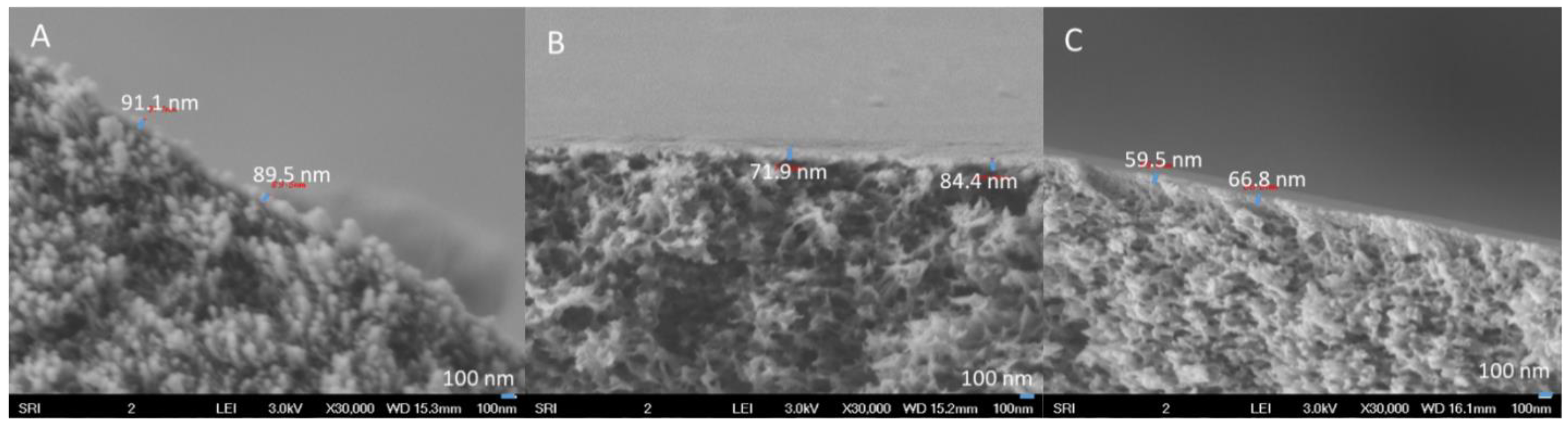
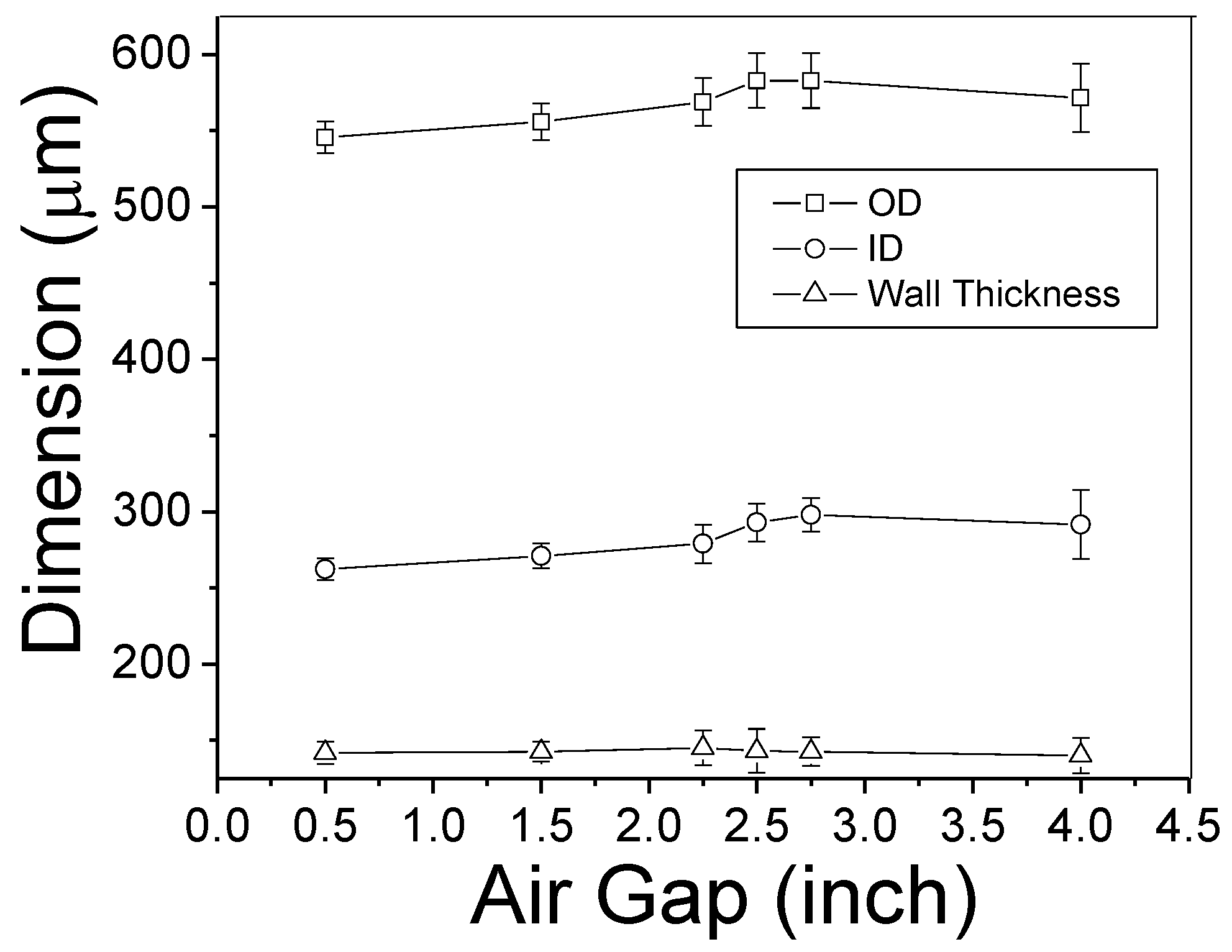
3.1. Morphology of PBI HFs
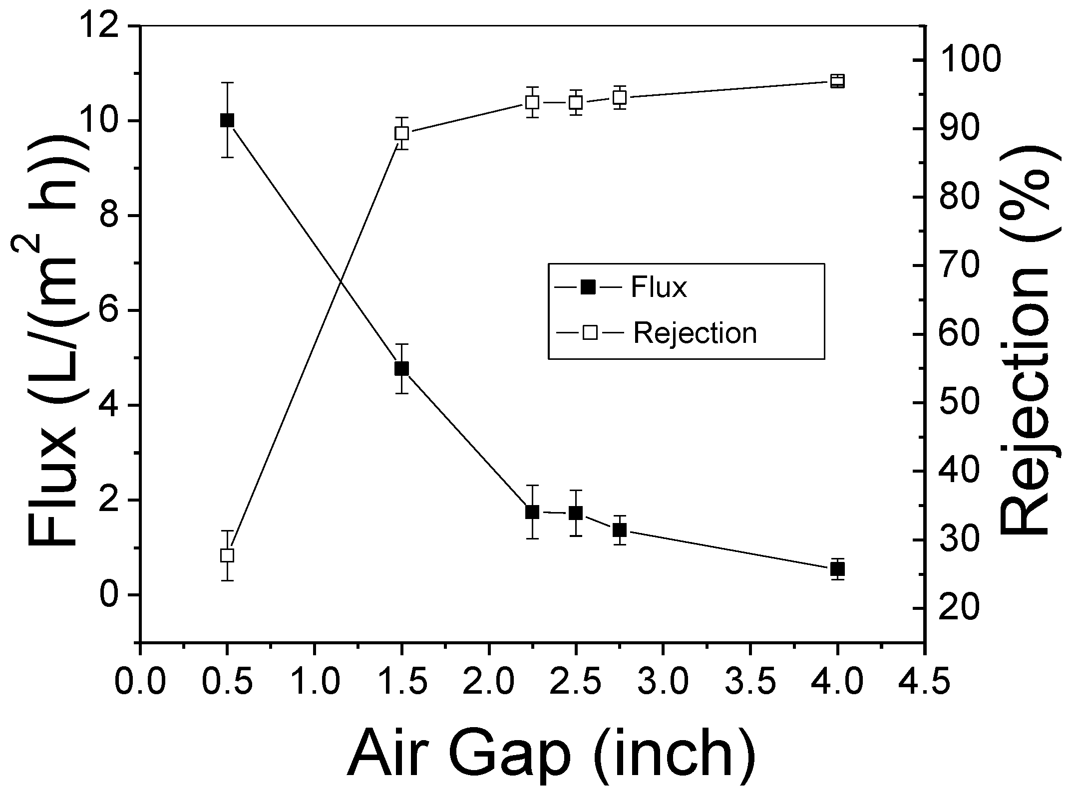
3.2. RO Test
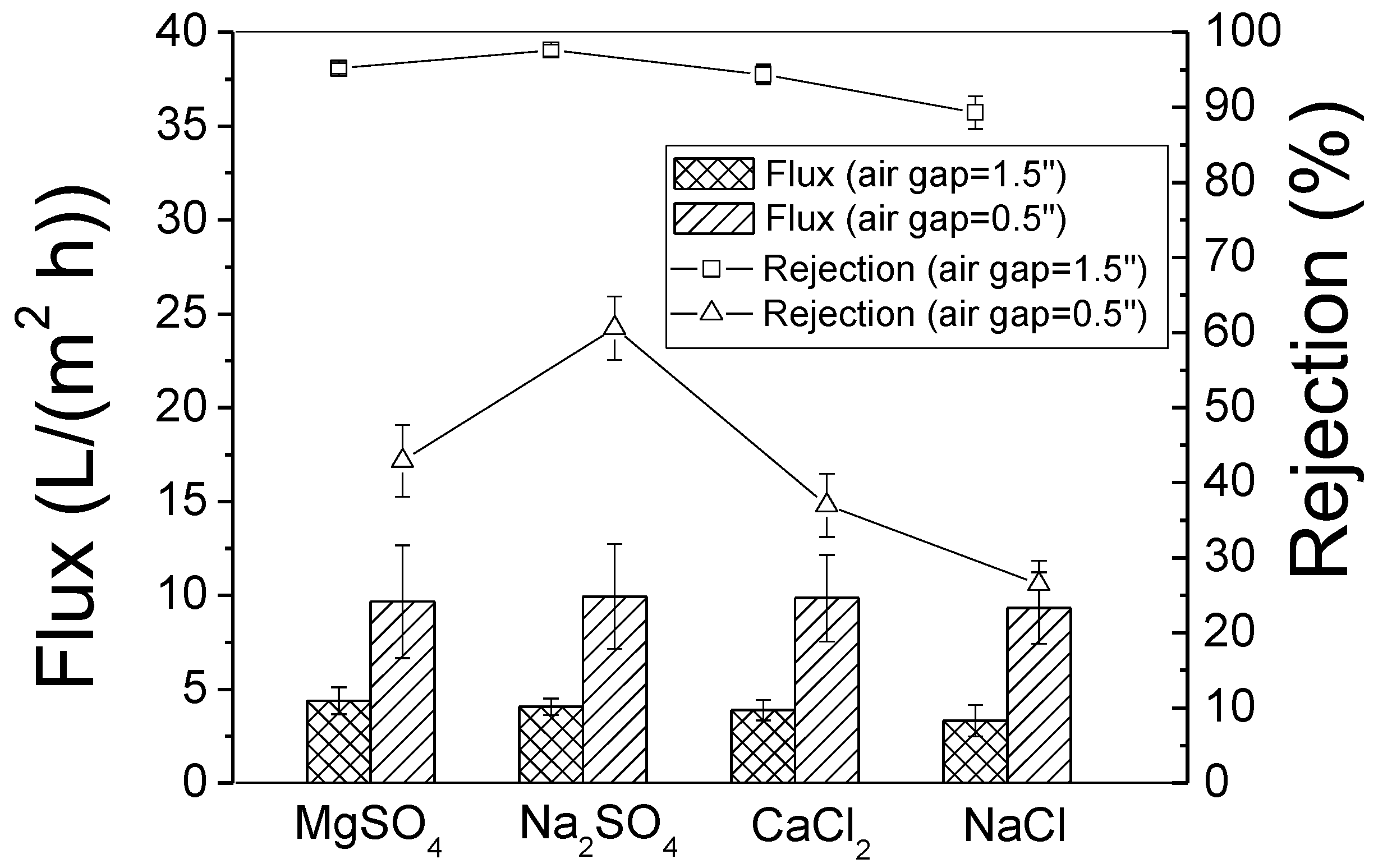
3.3. NF Test
4. Conclusions
Author Contributions
Funding
Acknowledgments
Conflicts of Interest
References
- Bourbigot, S.; Flambard, X. Heat resistance and flammability of high performance fibres: A review. Fire Mater. 2002, 26, 155–168. [Google Scholar] [CrossRef]
- Wang, K.Y.; Xiao, Y.; Chung, T.-S. Chemically modified polybenzimidazole nanofiltration membrane for the separation of electrolytes and cephalexin. Chem. Eng. Sci. 2006, 61, 5807–5817. [Google Scholar] [CrossRef]
- Chung, T.-S. A Critical Review of Polybenzimidazoles. J. Macromol. Sci. Part C 1997, 37, 277–301. [Google Scholar] [CrossRef]
- Tashvigh, A.A.; Chung, T.-S. Facile fabrication of solvent resistant thin fi lm composite membranes by interfacial crosslinking reaction between polyethylenimine and dibromo-p- xylene on polybenzimidazole substrates. J. Memb. Sci. 2018, 560, 115–124. [Google Scholar] [CrossRef]
- Asadi, A.; Luo, L.; Chung, T.-S.; Weber, M.; Maletzko, C. Performance enhancement in organic solvent nano fi ltration by double crosslinking technique using sulfonated polyphenylsulfone (sPPSU) and polybenzimidazole (PBI). J. Memb. Sci. 2018, 551, 204–213. [Google Scholar] [CrossRef]
- Lee, K.P.; Arnot, T.C.; Mattia, D. A review of reverse osmosis membrane materials for desalination—Development to date and future potential. J. Memb. Sci. 2011, 370, 1–22. [Google Scholar] [CrossRef] [Green Version]
- Wan, C.F.; Yang, T.; Lipscomb, G.G.; Stookey, D.J.; Chung, T.-S. Design and fabrication of hollow fiber membrane modules Design and fabrication of hollow fi ber membrane modules. J. Memb. Sci. 2017, 538, 96–107. [Google Scholar] [CrossRef]
- Sawyer, L.C.; Jones, R.S. Observations on the structure of first generation polybenzimidazole reverse osmosis membranes. J. Memb. Sci. 1984, 20, 147–166. [Google Scholar] [CrossRef]
- Senoo, M.; Hara, S.; Ozawa, S. Permselective Polymeric Membrane Prepared from Polybenzimidazoles. US3951920A, 20 April 1976. [Google Scholar]
- Mulder, J. Basic Principles of Membrane Technology; Springer Science & Business Media: Berlin, Germany, 1996; p. 18. ISBN 940091766X. [Google Scholar]
- Sadeghi, M.; Semsarzadeh, M.A.; Moadel, H. Enhancement of the gas separation properties of polybenzimidazole (PBI) membrane by incorporation of silica nano particles. J. Memb. Sci. 2009, 331, 21–30. [Google Scholar] [CrossRef]
- Kumbharkar, S.C.; Liu, Y.; Li, K. High performance polybenzimidazole based asymmetric hollow fibre membranes for H2/CO2 separation. J. Memb. Sci. 2011, 375, 231–240. [Google Scholar] [CrossRef]
- Zhu, W.; Sun, S.; Gao, J.; Fu, F.; Chung, T.-S. Dual-layer polybenzimidazole/polyethersulfone (PBI/PES) nano fi ltration (NF) hollow fi ber membranes for heavy metals removal from wastewater. J. Memb. Sci. 2014, 456, 117–127. [Google Scholar] [CrossRef]
- Fu, F.; Sun, S.; Zhang, S.; Chung, T.-S. Pressure retarded osmosis dual-layer hollow fi ber membranes developed by co-casting method and ammonium persulfate (APS) treatment. J. Memb. Sci. 2014, 469, 488–498. [Google Scholar] [CrossRef]
- Wang, Y.; Gruender, M.; Shung, T. Pervaporation dehydration of ethylene glycol through polybenzimidazole (PBI) -based membranes. 1. Membrane fabrication. J. Memb. Sci. 2010, 363, 149–159. [Google Scholar] [CrossRef]
- Sukitpaneenit, P.; Chung, T.-S. Molecular design of the morphology and pore size of PVDF hollow fiber membranes for ethanol—Water separation employing the modified pore-flow concept. J. Memb. Sci. 2011, 374, 67–82. [Google Scholar] [CrossRef]
- Chung, T.-S.; Hu, X. Effect of air-gap distance on the morphology and thermal properties of polyethersulfone hollow fibers. J. Appl. Polym. Sci. 1997, 66, 1067–1077. [Google Scholar] [CrossRef]
- Chung, T.-S.; Xu, Z.-L.; Lin, W. Fundamental Understanding of the Effect of Air-Gap\rDistance on the Fabrication of Hollow Fiber Membranes. J. Appl. Polym. Sci. 1999, 72, 379–395. [Google Scholar] [CrossRef]
- Khulbe, K.C.; Feng, C.Y.; Hamad, F.; Matsuura, T.; Khayet, M. Structural and performance study of micro porous polyetherimide hollow fiber membranes prepared at different air-gap. J. Memb. Sci. 2004, 245, 191–198. [Google Scholar] [CrossRef]
- Korminouri, F.; Rahbari-Sisakht, M.; Matsuura, T.; Ismail, A.F. Surface modification of polysulfone hollow fiber membrane spun under different air-gap lengths for carbon dioxide absorption in membrane contactor system. Chem. Eng. J. 2015, 264, 453–461. [Google Scholar] [CrossRef]
- Liu, Y.; Koops, G.H.; Strathmann, H. Characterization of morphology controlled polyethersulfone hollow fiber membranes by the addition of polyethylene glycol to the dope and bore liquid solution. J. Memb. Sci. 2003, 223, 187–199. [Google Scholar] [CrossRef] [Green Version]
- Khayet, M.; Feng, C.Y.; Khulbe, K.C.; Matsuura, T. Study on the effect of a non-solvent additive on the morphology and performance of ultrafiltration hollow-fiber membranes. Desalination 2002, 148, 321–327. [Google Scholar] [CrossRef]
- Yang, Q.; Chung, T.-S.; Santoso, Y.E. Tailoring pore size and pore size distribution of kidney dialysis hollow fiber membranes via dual-bath coagulation approach. J. Memb. Sci. 2007, 290, 153–163. [Google Scholar] [CrossRef]
- Khayet, M.; Feng, C.Y.; Khulbe, K.C.; Matsuura, T. Preparation and characterization of polyvinylidene fluoride hollow fiber membranes for ultrafiltration. Polymer (Guildf) 2002, 43, 3879–3890. [Google Scholar] [CrossRef]
- Wang, K.Y.; Yang, Q.; Chung, T.-S.; Rajagopalan, R. Enhanced forward osmosis from chemically modified polybenzimidazole (PBI) nanofiltration hollow fiber membranes with a thin wall. Chem. Eng. Sci. 2009, 64, 1577–1584. [Google Scholar] [CrossRef]
- Khayet, M. The effects of air gap length on the internal and external morphology of hollow fiber membranes. Chem. Eng. Sci. 2003, 58, 3091–3104. [Google Scholar] [CrossRef]
- Jayaweera, I.; Krishnan, G.N.; Sanjurjo, A.; Jayaweera, P.; Bhamidi, S. Process for Fabricating PBI Hollow Fiber Asymmetric Membranes for Gas Separation and Liquid Separation. US20140175007A1, 26 April 2016. [Google Scholar]
- Chung, T.-S.; Kafchinski, E.R. The effects of spinning conditions on asymmetric 6FDA/6FDAM polyimide hollow fibers for air separation. J. Appl. Polym. Sci. 1997, 65, 1555–1569. [Google Scholar] [CrossRef]
- Wang, K.Y.; Chung, T.-S.; Qin, J.J. Polybenzimidazole (PBI) nanofiltration hollow fiber membranes applied in forward osmosis process. J. Memb. Sci. 2007, 300, 6–12. [Google Scholar] [CrossRef]
- Smolders, C.A.; Reuvers, A.J.; Boom, R.M.; Wienk, I.M. Microstructures in phase-inversion membranes.\rPart 1. Formation of macrovoids. J. Membr. Sctence 1992, 73, 259–275. [Google Scholar] [CrossRef]
- Aiba, M.; Tokuyama, T.; Matsumoto, H.; Tomioka, H.; Higashihara, T.; Ueda, M. Effect of primary structure on permselectivity of ultrathin semipermeable polybenzimidazole membrane. J. Appl. Polym. Sci. 2014, 132, 1–7. [Google Scholar] [CrossRef]
- Wang, K.Y.; Chung, T.-S. Fabrication of polybenzimidazole (PBI) nanofiltration hollow fiber membranes for removal of chromate. J. Memb. Sci. 2006, 281, 307–315. [Google Scholar] [CrossRef]
- Williams, M.E. A Review of Reverse Osmosis Theory; EET Corporation and Williams Engineering Services Company Inc.: Harriman, TN, USA, 2003. [Google Scholar]
- Košutić, K.; Kaštelan-Kunst, L.; Kunst, B. Porosity of some commercial reverse osmosis and nanofiltration polyamide thin-film composite membranes. J. Memb. Sci. 2000, 168, 101–108. [Google Scholar] [CrossRef]
- Davis, H.J.; Soehngen, J.W. Chlorine Resistant PBI RO Permselective Membranes; Celanese Research Co.: Summit, NJ, USA, 1981. [Google Scholar]
- Munoz Elguera, A.; Nunez, A.; Nishida, M. Experimental test of TOYOBO membranes for seawater desalination at Las Palmas, Spain. Desalination 1999, 125, 55–64. [Google Scholar] [CrossRef]
- Tansel, B.; Sager, J.; Rector, T.; Garland, J.; Strayer, R.F.; Levine, L.; Roberts, M.; Hummerick, M.; Bauer, J. Significance of hydrated radius and hydration shells on ionic permeability during nanofiltration in dead end and cross flow modes. Sep. Purif. Technol. 2006, 51, 40–47. [Google Scholar] [CrossRef]


© 2018 by the authors. Licensee MDPI, Basel, Switzerland. This article is an open access article distributed under the terms and conditions of the Creative Commons Attribution (CC BY) license (http://creativecommons.org/licenses/by/4.0/).
Share and Cite
Wang, X.; Jayaweera, P.; Alrasheed, R.A.; Aljlil, S.A.; Alyousef, Y.M.; Alsubaei, M.; AlRomaih, H.; Jayaweera, I. Preparation of Polybenzimidazole Hollow-Fiber Membranes for Reverse Osmosis and Nanofiltration by Changing the Spinning Air Gap. Membranes 2018, 8, 113. https://doi.org/10.3390/membranes8040113
Wang X, Jayaweera P, Alrasheed RA, Aljlil SA, Alyousef YM, Alsubaei M, AlRomaih H, Jayaweera I. Preparation of Polybenzimidazole Hollow-Fiber Membranes for Reverse Osmosis and Nanofiltration by Changing the Spinning Air Gap. Membranes. 2018; 8(4):113. https://doi.org/10.3390/membranes8040113
Chicago/Turabian StyleWang, Xiao, Palitha Jayaweera, Radwan A. Alrasheed, Saad A. Aljlil, Yousef M. Alyousef, Mohammad Alsubaei, Hamad AlRomaih, and Indira Jayaweera. 2018. "Preparation of Polybenzimidazole Hollow-Fiber Membranes for Reverse Osmosis and Nanofiltration by Changing the Spinning Air Gap" Membranes 8, no. 4: 113. https://doi.org/10.3390/membranes8040113