Antifouling Property of Oppositely Charged Titania Nanosheet Assembled on Thin Film Composite Reverse Osmosis Membrane for Highly Concentrated Oily Saline Water Treatment

Abstract
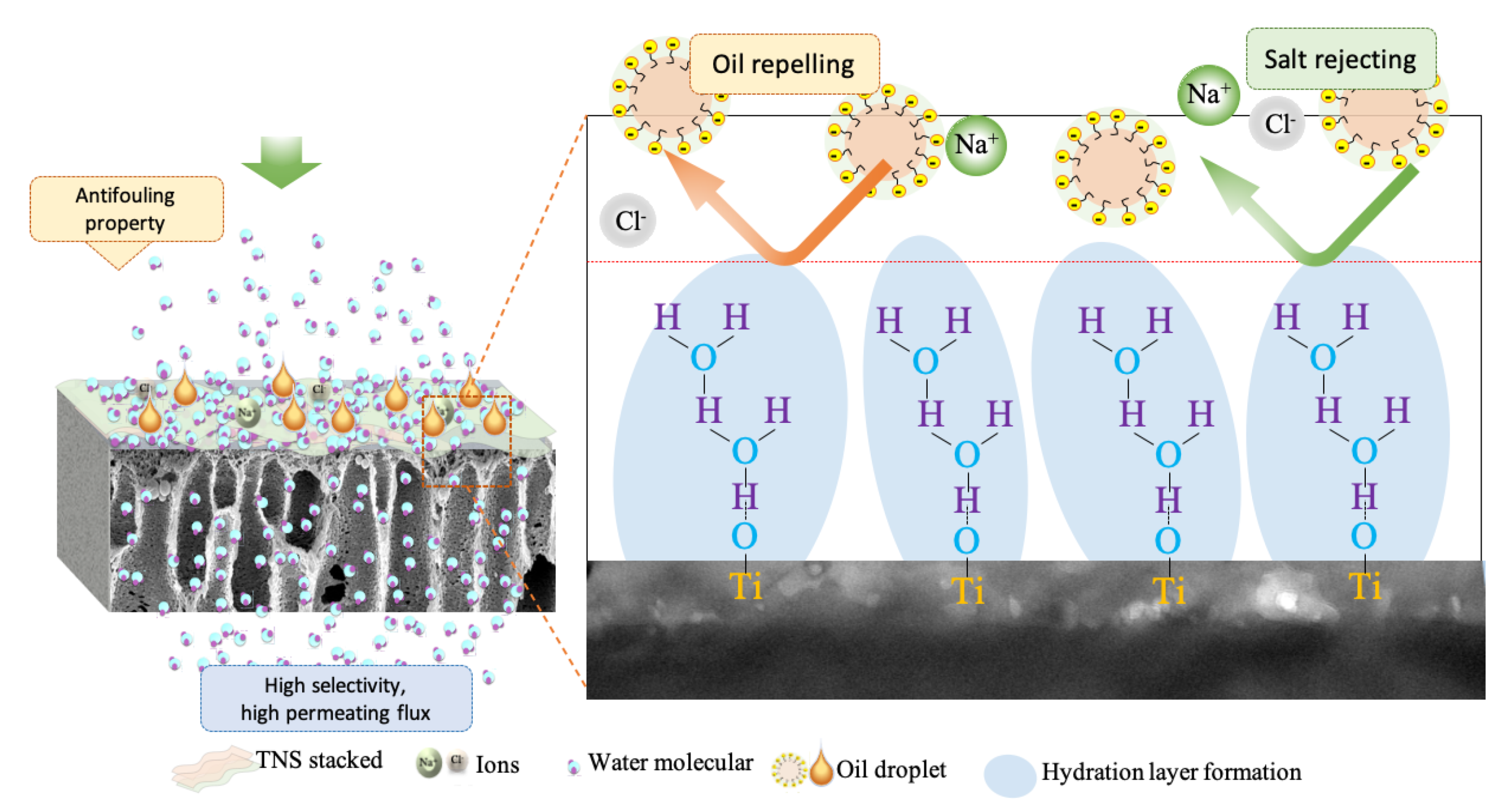
:
1. Introduction
2. Materials and Methods
2.1. Materials
2.2. Preparation of PA Composite Membrane with TNS Bilayers
2.3. Characterization of Membrane
2.4. Evaluation of Membrane Performance by RO Testing Mode
2.4.1. Water Permeability and Rejection Test of Saline Water
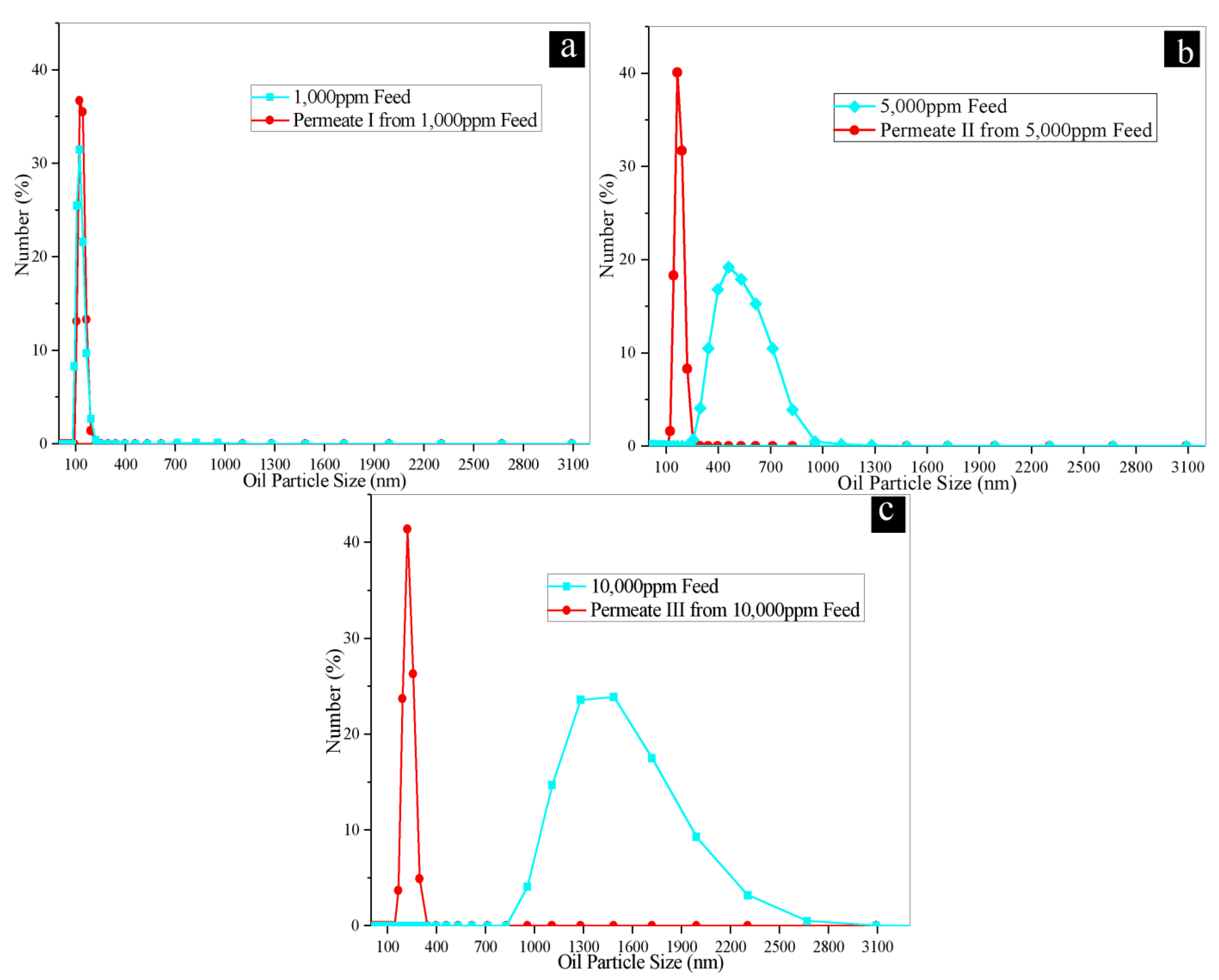
2.4.2. Water Permeability and Rejection Test of Synthetic Oily Saline Water
2.4.3. Antifouling Test
3. Results and Discussion
3.1. Effect of TNS Loading on Membrane Chemistry
3.1.1. Surface Hydrophilicity of TNS-PA TFN Membranes
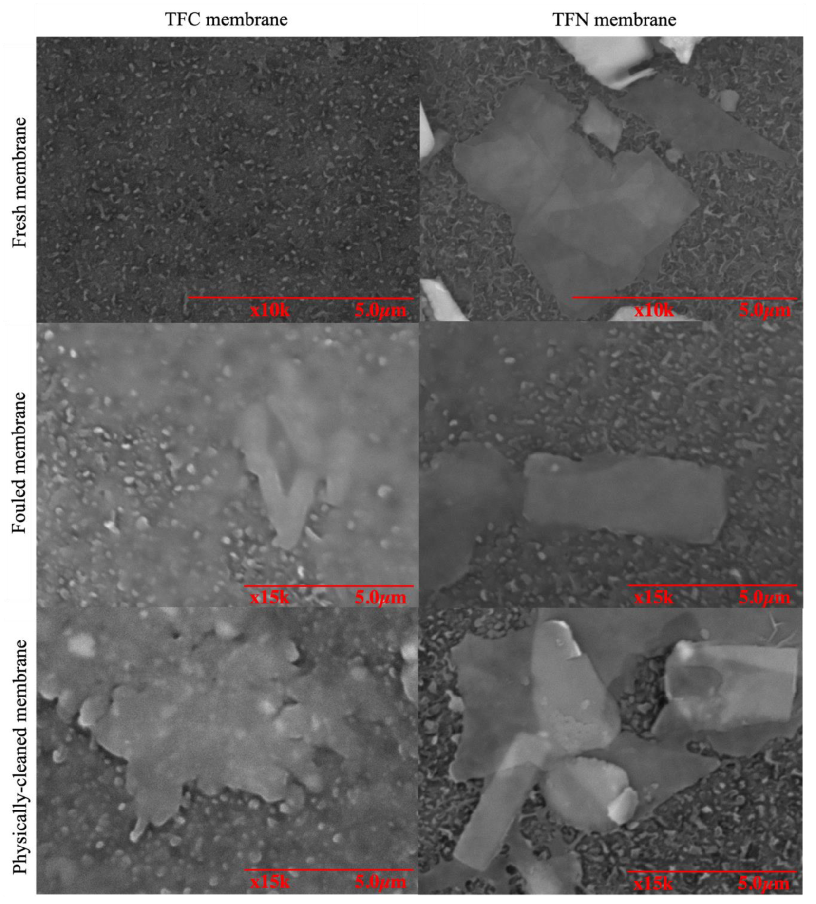
3.1.2. Morphology and Chemical Compositions of TNS-PA TFN Membranes
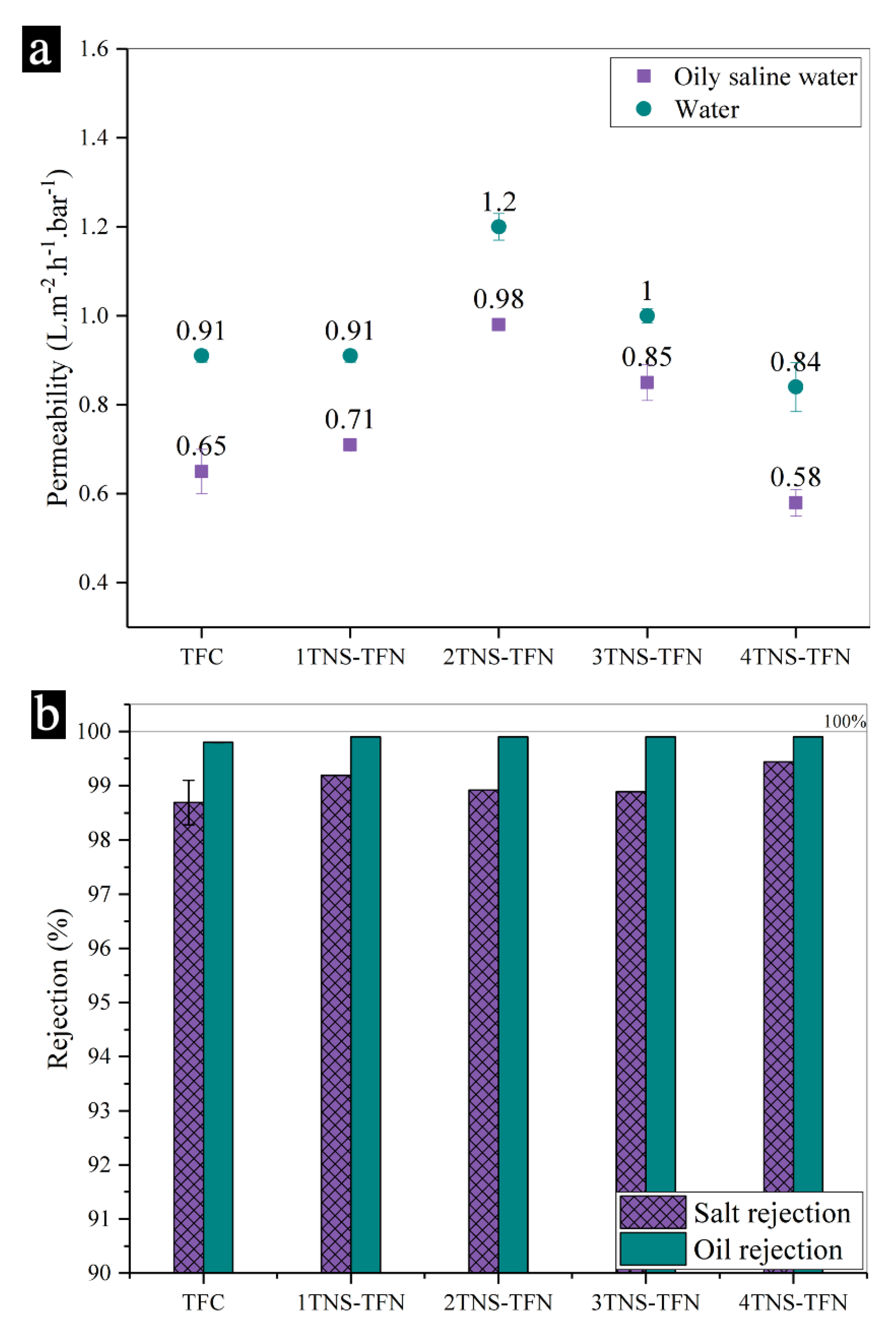
3.2. Separation Performance of Membranes
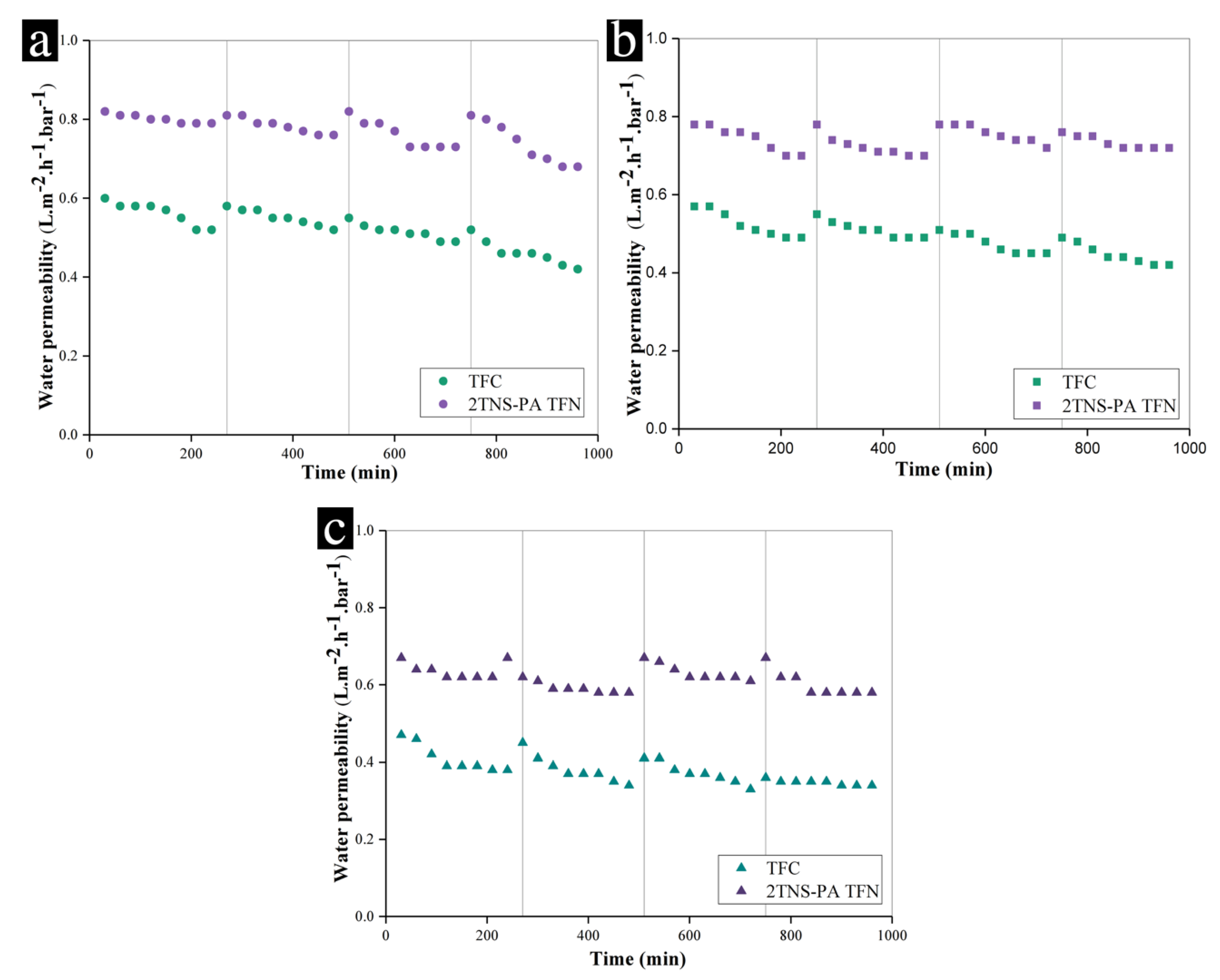
3.3. Antifouling Behaviour of Membranes
4. Conclusions
Supplementary Materials
Author Contributions
Funding
Conflicts of Interest
References
- Alsalhy, Q.F.; Albyati, T.M.; Zablouk, M.A. A study of the effect of operating conditions on reverse osmosis membrane performance with and without air sparging technique. Chem. Eng. Commun. 2013, 200, 1–19. [Google Scholar] [CrossRef]
- Ahmad, N.A.; Goh, P.S.; Karim, Z.A.; Ismail, A.F. Thin film composite membrane for oily waste water treatment: Recent advances and challenges. Membranes 2018, 8, 86. [Google Scholar] [CrossRef] [PubMed] [Green Version]
- Jamshidi Gohari, R.; Korminouri, F.; Lau, W.J.; Ismail, A.F.; Matsuura, T.; Chowdhury, M.N.K.; Halakoo, E.; Jamshidi Gohari, M.S. A novel super-hydrophilic PSf/HAO nanocomposite ultrafiltration membrane for efficient separation of oil/water emulsion. Sep. Purif. Technol. 2015, 150, 13–20. [Google Scholar] [CrossRef]
- Ge, Q.; Amy, G.L.; Chung, T.S. Forward osmosis for oily wastewater reclamation: Multi-charged oxalic acid complexes as draw solutes. Water Res. 2017, 122, 580–590. [Google Scholar] [CrossRef] [Green Version]
- Maltos, R.A.; Regnery, J.; Almaraz, N.; Fox, S.; Schutter, M.; Cath, T.J.; Veres, M.; Coday, B.D.; Cath, T.Y. Produced water impact on membrane integrity during extended pilot testing of forward osmosis—Reverse osmosis treatment. Desalination 2018, 440, 99–110. [Google Scholar] [CrossRef]
- Elhady, S.; Bassyouni, M.; Mansour, R.A.; Elzahar, M.H.; Abdel-Hamid, S.; Elhenawy, Y.; Saleh, M.Y. Oily wastewater treatment using polyamide thin film composite membrane technology. Membranes 2020, 10, 84. [Google Scholar] [CrossRef] [PubMed]
- Ostarcevic, E.R.; Jacangelo, J.; Gray, S.R.; Cran, M.J. Current and emerging techniques for high-pressure membrane integrity testing. Membranes 2018, 8, 60. [Google Scholar] [CrossRef] [Green Version]
- Al-Jeshi, S.; Neville, A. An experimental evaluation of reverse osmosis membrane performance in oily water. Desalination 2008, 228, 287–294. [Google Scholar] [CrossRef]
- Baransi-Karkaby, K.; Bass, M.; Freger, V. In situ modification of reverse osmosis membrane elements for enhanced removal of multiple micropollutants. Membranes 2019, 9, 28. [Google Scholar] [CrossRef] [Green Version]
- Pei, B.; Chen, J.; Liu, P.; He, T.; Li, X.; Zhang, L. Hyperbranched poly(amidoamine)/TMC reverse osmosis membrane for oily saline water treatment. Environ. Technol. 2018, 40, 2779–2788. [Google Scholar] [CrossRef]
- Li, M.; Ishihara, S.; Ji, Q.; Akada, M.; Hill, J.P.; Ariga, K. Paradigm shift from self-assembly to commanded assembly of functional materials: Recent examples in porphyrin/fullerene supramolecular systems. Sci. Technol. Adv. Mater. 2012, 13. [Google Scholar] [CrossRef] [PubMed]
- Yang, Z.; Zhou, Y.; Feng, Z.; Rui, X.; Zhang, T.; Zhang, Z. A Review on Reverse Osmosis and Nanofiltration Membranes for Water Purification. Polymers 2019, 11, 1252. [Google Scholar] [CrossRef] [PubMed] [Green Version]
- Xu, P.; Drewes, J.E.; Heil, D. Beneficial use of co-produced water through membrane treatment: Technical-economic assessment. Desalination 2008, 225, 139–155. [Google Scholar] [CrossRef]
- Greenlee, L.F.; Lawler, D.F.; Freeman, B.D.; Marrot, B.; Moulin, P. Reverse osmosis desalination: Water sources, technology, and today’s challenges. Water Res. 2009, 43, 2317–2348. [Google Scholar] [CrossRef] [PubMed]
- Jhaveri, J.H.; Murthy, Z.V.P. A comprehensive review on anti-fouling nanocomposite membranes for pressure driven membrane separation processes. Desalination 2016, 379, 137–154. [Google Scholar] [CrossRef]
- Igunnu, E.T.; Chen, G.Z. Produced water treatment technologies. Int. J. Low Carbon Technol. 2014, 9, 157–177. [Google Scholar] [CrossRef] [Green Version]
- Liu, L.F.; Gu, X.L.; Qi, S.R.; Xie, X.; Li, R.H.; Li, K.; Yu, C.Y.; Gao, C.J. Modification of Polyamide-urethane (PAUt) thin film composite membrane for improving the reverse osmosis performance. Polymers 2018, 10, 346. [Google Scholar] [CrossRef] [Green Version]
- McCloskey, B.D.; Park, H.B.; Ju, H.; Rowe, B.W.; Miller, D.J.; Freeman, B.D. A bioinspired fouling-resistant surface modification for water purification membranes. J. Membr. Sci. 2012, 413–414, 82–90. [Google Scholar] [CrossRef]
- Zhang, Y.; Wan, Y.; Pan, G.; Yan, H.; Yao, X.; Shi, H.; Tang, Y.; Wei, X.; Liu, Y. Surface modification of polyamide reverse osmosis membrane with organic-inorganic hybrid material for antifouling. Appl. Surf. Sci. 2018, 433, 139–148. [Google Scholar] [CrossRef]
- Zaidi, S.M.J.; Mauritz, K.A.; Hassan, M.K. Membrane Surface Modification and Functionalization. In Functional Polymers; Springer International Publishing: Cham, Switzerland, 2019; pp. 391–416. ISBN 9783319920672. [Google Scholar]
- Jafarinejad, S. A Comprehensive Study on the Application of Reverse Osmosis (RO) Technology for the Petroleum Industry Wastewater Treatment. J. Water Environ. Nanotechnol. 2017, 2, 243–264. [Google Scholar] [CrossRef]
- Ahmad, N.A.; Goh, P.S.; Wong, K.C.; Zulhairun, A.K.; Ismail, A.F. Enhancing desalination performance of thin film composite membrane through layer by layer assembly of oppositely charged titania nanosheet. Desalination 2020, 476, 114167. [Google Scholar] [CrossRef]
- Huang, S.; Ras, R.H.A.; Tian, X. Antifouling membranes for oily wastewater treatment: Interplay between wetting and membrane fouling. Curr. Opin. Colloid Interface Sci. 2018, 36, 90–109. [Google Scholar] [CrossRef]
- Garud, R.M.; Kore, S.V.; Kore, V.S.; Kulkarni, G.S. A Short Review on Process and Applications of Reverse Osmosis. Univers. J. Environ. Res. Technol. 2011, 1, 233–238. [Google Scholar] [CrossRef]
- Mayyahi, A. Al Important Approaches to Enhance Reverse Osmosis ( RO ) Thin Film Composite ( TFC ) Membranes Performance. Membranes 2018, 8, 68. [Google Scholar] [CrossRef] [PubMed] [Green Version]
- Ji, L.; Liu, Y.; Zhang, Y.; Liu, X. Study on the treatment of high salinity oil waste water by reverse osmosis technology. Adv. Mater. Res. 2012, 418–420, 90–93. [Google Scholar] [CrossRef]
- Kasemset, S.; Lee, A.; Miller, D.J.; Freeman, B.D.; Sharma, M.M. Effect of polydopamine deposition conditions on fouling resistance, physical properties, and permeation properties of reverse osmosis membranes in oil/water separation. J. Membr. Sci. 2013, 425–426, 208–216. [Google Scholar] [CrossRef]
- Chen, L.; Thérien-Aubin, H.; Wong, M.C.Y.; Hoek, E.M.V.; Ober, C.K. Improved antifouling properties of polymer membranes using a ‘layer-by-layer’ mediated method. J. Mater. Chem. B 2013, 1, 5651. [Google Scholar] [CrossRef]
- Xu, G.R.; Wang, J.N.; Li, C.J. Strategies for improving the performance of the polyamide thin film composite (PA-TFC) reverse osmosis (RO) membranes: Surface modifications and nanoparticles incorporations. Desalination 2013, 328, 83–100. [Google Scholar] [CrossRef]
- Ishigami, T.; Amano, K.; Fujii, A.; Ohmukai, Y.; Kamio, E.; Maruyama, T.; Matsuyama, H. Fouling reduction of reverse osmosis membrane by surface modification via layer-by-layer assembly. Sep. Purif. Technol. 2012, 99, 1–7. [Google Scholar] [CrossRef]
- Choi, W.; Choi, J.; Bang, J.; Lee, J. Layer-by-Layer Assembly of Graphene Oxide Nanosheets on Polyamide Membranes for Durable Reverse Osmosis Applications. Acs Appl. Mater. Interfaces 2013, 5, 12510–12519. [Google Scholar] [CrossRef]
- Shao, F.; Xu, C.; Ji, W.; Dong, H.; Sun, Q.; Yu, L.; Dong, L. Layer-by-layer self-assembly TiO2and graphene oxide on polyamide reverse osmosis membranes with improved membrane durability. Desalination 2017, 423, 21–29. [Google Scholar] [CrossRef]
- Cho, J.; Sung, H.; Choi, W.; Choi, J.; Ko, Y.; Lee, S.; Bang, J. Layer-by-Layer Assembly of Inorganic Nanosheets and Polyelectrolytes for Reverse Osmosis Composite Membranes. J. Chem. Eng. Jpn. 2014, 47, 180–186. [Google Scholar] [CrossRef]
- Wang, Y.; Wang, Z.; Han, X.; Wang, J.; Wang, S. Improved flux and anti-biofouling performances of reverse osmosis membrane via surface layer-by-layer assembly. J. Membr. Sci. 2017, 539, 403–411. [Google Scholar] [CrossRef]
- Yu, Y.; Zhang, P.; Guo, L.; Chen, Z.; Wu, Q.; Ding, Y.; Zheng, W.; Cao, Y. The design of TiO 2 nanostructures (nanoparticle, nanotube, and nanosheet) and their photocatalytic activity. J. Phys. Chem. C 2014, 118, 12727–12733. [Google Scholar] [CrossRef]
- Lai, G.S.; Lau, W.J.; Goh, P.S.; Ismail, A.F.; Tan, Y.H.; Chong, C.Y.; Krause-Rehberg, R.; Awad, S. Tailor-made thin film nanocomposite membrane incorporated with graphene oxide using novel interfacial polymerization technique for enhanced water separation. Chem. Eng. J. 2018, 344, 524–534. [Google Scholar] [CrossRef]
- Ghosh, A.K.; Jeong, B.H.; Huang, X.; Hoek, E.M.V. Impacts of reaction and curing conditions on polyamide composite reverse osmosis membrane properties. J. Membr. Sci. 2008, 311, 34–45. [Google Scholar] [CrossRef]
- Kardena, E.; Hidayat, S.; Nora, S.; Helmy, Q. Biological Treatment of Synthetic Oilfield-Produced Water in Activated Sludge Using a Consortium of Endogenous Bacteria Isolated from A Tropical Area. J. Pet. Environ. Biotechnol. 2017, 8. [Google Scholar] [CrossRef]
- Ong, C.S.; Al-Anzi, B.; Lau, W.J.; Goh, P.S.; Lai, G.S.; Ismail, A.F.; Ong, Y.S. Anti-Fouling Double-Skinned Forward Osmosis Membrane with Zwitterionic Brush for Oily Wastewater Treatment. Sci. Rep. 2017, 7, 6904. [Google Scholar] [CrossRef] [Green Version]
- Lee, W.J.; Goh, P.S.; Lau, W.J.; Ong, C.S.; Ismail, A.F. Antifouling zwitterion embedded forward osmosis thin film composite membrane for highly concentrated oily wastewater treatment. Sep. Purif. Technol. 2018, 214, 40–50. [Google Scholar] [CrossRef]
- Rajaeian, B.; Rahimpour, A.; Tade, M.O.; Liu, S. Fabrication and characterization of polyamide thin film nanocomposite (TFN) nanofiltration membrane impregnated with TiO2 nanoparticles. Desalination 2013, 313, 176–188. [Google Scholar] [CrossRef]
- Chen, Y.; Liu, C.; Setiawan, L.; Wang, Y.N.; Hu, X.; Wang, R. Enhancing pressure retarded osmosis performance with low-pressure nanofiltration pretreatment: Membrane fouling analysis and mitigation. J. Membr. Sci. 2017, 543, 114–122. [Google Scholar] [CrossRef]
- Khorshidi, B.; Biswas, I.; Ghosh, T.; Thundat, T.; Sadrzadeh, M. Robust fabrication of thin film polyamide-TiO2nanocomposite membranes with enhanced thermal stability and anti-biofouling propensity. Sci. Rep. 2018, 8, 784. [Google Scholar] [CrossRef]
- Sagle, A.C.; Van Wagner, E.M.; Ju, H.; Mccloskey, B.D.; Freeman, B.D.; Sharma, M.M. PEG-coated reverse osmosis membranes: Desalination properties and fouling resistance. J. Membr. Sci. 2009, 340, 92–108. [Google Scholar] [CrossRef]
- Zirehpour, A.; Rahimpour, A.; Arabi Shamsabadi, A.; Sharifian, M.G.; Soroush, M. Mitigation of Thin-Film Composite Membrane Biofouling via Immobilizing Nano-Sized Biocidal Reservoirs in the Membrane Active Layer. Environ. Sci. Technol. 2017, 51, 5511–5522. [Google Scholar] [CrossRef] [PubMed]
- Yang, R.; Xu, J.; Ozaydin-ince, G.; Wong, S.Y.; Gleason, K.K. Surface-Tethered Zwitterionic Ultrathin Antifouling Coatings on Reverse Osmosis Membranes by Initiated Chemical Vapor Deposition. Chem. Mater. 2011, 23, 1263–1272. [Google Scholar] [CrossRef]
- Lü, T.; Zhang, S.; Qi, D.; Zhang, D.; Vance, G.F.; Zhao, H. Synthesis of pH-sensitive and recyclable magnetic nanoparticles for efficient separation of emulsified oil from aqueous environments. Appl. Surf. Sci. 2017, 396, 1604–1612. [Google Scholar] [CrossRef]
- Lonsdale, H.K.; Merten, U.; Riley, R.L.; Jay, J. Transport Properties of Cellulose Acetate Osmotic Membranes. J. Appl. Polym. Sci. 1965, 9, 1341–1362. [Google Scholar] [CrossRef]
- Ahmad, T.; Guria, C.; Mandal, A. Synthesis, characterization and performance studies of mixed-matrix poly(vinyl chloride)-bentonite ultrafiltration membrane for the treatment of saline oily wastewater. Process Saf. Environ. Prot. 2018, 116, 703–717. [Google Scholar] [CrossRef]
- Wang, Z.; Elimelech, M.; Lin, S. Environmental Applications of Interfacial Materials with Special Wettability. Environ. Sci. Technol. 2016, 50. [Google Scholar] [CrossRef] [Green Version]
- Tummons, E.N.; Chew, J.W.; Fane, A.G.; Tarabara, V.V. Ultrafiltration of saline oil-in-water emulsions stabilized by an anionic surfactant: Effect of surfactant concentration and divalent counterions. J. Membr. Sci. 2017, 537, 384–395. [Google Scholar] [CrossRef]
- Qin, D.; Liu, Z.; Bai, H.; Sun, D.D.; Song, X. A new nano-engineered hierarchical membrane for concurrent removal of surfactant and oil from oil-in-water nanoemulsion. Sci. Rep. 2016, 6, 24365. [Google Scholar] [CrossRef] [PubMed] [Green Version]
- Huang, J.; Wang, Z.; Zhang, J.; Zhang, X.; Wu, Z. A novel composite conductive microfiltration membrane and its anti-fouling performance with an external electric field in membrane bioreactors. Sci. Rep. 2015, 5, 9268. [Google Scholar] [CrossRef] [PubMed] [Green Version]
- Kusnierz, M.; Wiercik, P. Analysis of particle size and fractal dimensions of suspensions contained in raw sewage, treated sewage and activated sludge. Arch. Environ. Prot. 2016, 42, 67–76. [Google Scholar] [CrossRef] [Green Version]
- Hidajat, M.J.; Jo, W.; Kim, H.; Noh, J. Effective Droplet Size Reduction and Excellent Stability of Limonene Nanoemulsion Formed by High-Pressure Homogenizer. Colloids Interfaces 2020, 4, 5. [Google Scholar] [CrossRef] [Green Version]
- Wang, Z.; Lin, S. Membrane fouling and wetting in membrane distillation and their mitigation by novel membranes with special wettability. Water Res. 2017, 112, 38–47. [Google Scholar] [CrossRef]


| Membrane | Atomic Concentration (%) | O/N Ratio | O/N Ratio | Degree of Cross-Linking (%) | |||
|---|---|---|---|---|---|---|---|
| C (1s) | O (1s) | N (1s) | Ti (2p) | ||||
| TFC | 75.35 | 13.39 | 11.26 | - | 1.19 | 6.69 | 74.10 |
| 2TNS-PA TFN | 56.00 | 30.03 | 5.87 | 8.10 | 5.12 | 9.54 | 33.53 |
| Membrane Type | Cross-Linked Portion of Amide Linkages/m (%) | Linear Portion of Carboxylic Groups/n (%) |
|---|---|---|
| TFC | 74.10 | 25.90 |
| 2TNS-PA TFN | 33.53 | 66.47 |
| Membrane | Flux | Rejection | Long Term Performance | Ref. | |
|---|---|---|---|---|---|
| Flux Drop | Flux Recovery | ||||
| Commercial RO (RE-4040) Feed: 4800–5500 ppm of salts 9–13 ppm petrolic | 50–55 L·m−2·h−1 | ~99.9% of total organic carbon (TOC) 96.6% of salt | -After 15 h, flux declined 75% of its initial flux | -Recovery 100% (restored to its original state) | [26] |
| PSf-PAMAM+TMC Feed: 2.5 or 5 mL hexadecane 2000 ppm salt 250 mg SDS | 18.42 L·m−2·h−1 | 99% of TOC 89.3% of salt | -After 18 h, flux declined 5% -After 24 h, flux declined 30% | [10] | |
| Commercial RO incorporated with polydopamine Feed: 1500 ppm of soybean oil soybean oil 2000 ppm salt | >40 L·m−2·h−1 | >99.1% of salt | -After 1 h, flux improved 30–50% from TFC | -Recovery 100% (restored to its original state) | [27] |
| PSf-MPD+TMC incorporated with TNS bilayers Feed: 1000 ppm oil 2000 ppm of salt | 14.7 L·m−2·h−1 | >99% of oil >99% of salt | -After 4 h, flux declined 5% -After 16 h, flux declined 17% | -Recovery 100% (restored to its original state) | This study |
© 2020 by the authors. Licensee MDPI, Basel, Switzerland. This article is an open access article distributed under the terms and conditions of the Creative Commons Attribution (CC BY) license (http://creativecommons.org/licenses/by/4.0/).
Share and Cite
Ahmad, N.A.; Goh, P.S.; Zulhairun, A.K.; Ismail, A.F. Antifouling Property of Oppositely Charged Titania Nanosheet Assembled on Thin Film Composite Reverse Osmosis Membrane for Highly Concentrated Oily Saline Water Treatment. Membranes 2020, 10, 237. https://doi.org/10.3390/membranes10090237
Ahmad NA, Goh PS, Zulhairun AK, Ismail AF. Antifouling Property of Oppositely Charged Titania Nanosheet Assembled on Thin Film Composite Reverse Osmosis Membrane for Highly Concentrated Oily Saline Water Treatment. Membranes. 2020; 10(9):237. https://doi.org/10.3390/membranes10090237
Chicago/Turabian StyleAhmad, Nor Akalili, Pei Sean Goh, Abdul Karim Zulhairun, and Ahmad Fauzi Ismail. 2020. "Antifouling Property of Oppositely Charged Titania Nanosheet Assembled on Thin Film Composite Reverse Osmosis Membrane for Highly Concentrated Oily Saline Water Treatment" Membranes 10, no. 9: 237. https://doi.org/10.3390/membranes10090237