High-Efficiency Dual-Frequency Reflective Linear Polarization Converter Based on Metasurface for Microwave Bands


1
College of Materials Science and Chemical Engineering, Harbin Engineering University, Harbin 150001, China
2
School of Electronics Science, Northeast Petroleum University, Daqing 163318, China
3
Media Lab, Massachusetts Institute of Technology, Cambridge, MA 02139, USA
4
Department of Physics and Department of Materials Science and Engineering, City University of Hong Kong, Hong Kong 999077, China
*
Authors to whom correspondence should be addressed.
Appl. Sci. 2019, 9(9), 1910; https://doi.org/10.3390/app9091910
Submission received: 12 April 2019
/
Revised: 29 April 2019
/
Accepted: 7 May 2019
/
Published: 9 May 2019
Abstract
:A dual-broadband and high-efficiency reflective linear polarization converter based on an anisotropic metasurface is presented. The device consists of two symmetrical, double-slotted metallic split-rings and one criss-cross structure, a dielectric layer, and a completely reflective metallic ground. The converter exhibits four resonances and can near-perfectly convert x- or y-polarized incident waves into cross-polarized waves in the frequency ranges of 9.38–13.36 GHz and 14.84–20.36 GHz. The polarization conversion ratios (PCRs) of the two bands are 98.21% and 99.32%, respectively. The energy conversion ratio (ECR) for energy loss measurement is almost 100% in these frequency bands. The polarization conversion principle is studied. The bandwidths and PCRs of the two bands are determined by varying the dielectric layer thickness. The simulation results are consistent with experimental observations. The designed dual-broadband and high-efficiency metasurface has great potential in the application of electromagnetic polarization control.
1. Introduction
The polarization of an electromagnetic (EM) wave is concerned with the oscillation direction of the electric field in the plane lying perpendicular to the propagation direction [1]. Polarization is one of the most basic characteristics of EM waves, and has significant applications in many fields including antennas [2,3,4,5], asymmetric transmission [6,7,8,9], biological detection [7], and microwave communication [10,11,12,13,14,15,16]. Many applications of EM phenomena are very sensitive to polarization [17,18,19,20]. Hence, it is necessary to precisely control and manipulate the polarization states of EM waves. The traditional way to manipulate polarization is to use natural materials such as twisted nematic liquid crystals by utilizing the Faraday effect [21]. It means that sufficient phase accumulation occurs at the expense of a longer transmission distance. Therefore, the traditional polarization converters have a large volume and narrow bandwidths, rendering device miniaturization difficult. Fortunately, metasurface is a type of artificial layered material with a thickness that is less than the operating wavelength. Metasurfaces enable the flexible and effective control of EM waves and have many unique properties [22,23,24]. Many types of metasurface-based polarization converters have been designed because of their high efficiency, low profile, and small size [25,26,27,28,29,30]. For example, Li et al. [31] designed a wide-band, multi-purpose, and switchable linear polarization converter based on a metasurface. Yu et al. [32] proposed a V-shaped nanoantenna to achieve line-to-circular polarization conversion in the optical frequency band. A cross-reflective polarization converter operating over a large frequency range with high efficiency was reported by Chen et al. [33]. The chiral metasurface is considered to be an effective method for transmission polarization manipulation components which can convert all polarization types, including linear-to-circular, linear-to-linear, and circular-to-circular polarization conversion. Chiral metasurface can achieve high conversion efficiency; however, it has the disadvantages of a complex multilayer structure and a narrow bandwidth. These restrict its practical applications. For reflective polarization conversion, the above mentioned problems can be avoided by using anisotropic structures [34,35,36]. Moreover, the operating bandwidth can be increased to a certain extent by the superposition of different resonant frequencies. For example, Zhao et al. [37] presented a broadband and high-efficiency linear polarization rotator based on anisotropic structures, which achieved 90° polarization rotation from 5.7 to 10.3 GHz and a polarization conversion ratio (PCR) above 90%. However, little information has been provided about dual-broadband or multi-broadband polarization converters with the polarization conversion efficiency close to 1, which are crucial to EM wave applications. For example, the dual-broadband polarization converter can improve the capacity and speed of data transmission when it is used in a wireless communication system. The system compatibility can also be improved as it works in two different frequency ranges. Therefore, it is very important to design a dual-frequency or multi-frequency polarization converter with a polarization conversion efficiency that is close to 1.
In this work, a high-efficiency and dual-broadband linear polarization converter based on a reflective metasurface is proposed, constructed, and evaluated. The converter is composed of two symmetrical double-slotted metallic split-rings and one criss-cross structure, a dielectric layer, and a metallic ground, as well as four resonances within the 9.38–13.36 GHz and 14.84–20.36 GHz frequency ranges. The x-polarized or y-polarized incident wave can be converted almost perfectly into the corresponding cross-polarized wave in these dual-band ranges. The PCRs for the two bands are more than 98.21% and 99.32%, respectively. The effect of the dielectric layer thickness on the polarization conversion performance is studied. The results show that when the PCR and bandwidths of the two operating bands are considered, the dielectric layer thickness can be optimized to deliver outstanding dual broadband performance.
2. Design, Simulation, and Theoretical Analysis
Figure 1 shows the schematic diagram of the unit cell structure of the designed polarization converter with a three-layered metal-dielectric-metal structure. The top metallic structure consists of two symmetrical double slot metallic open rings and one criss-cross structure, which is placed 45° forward with respect to the +x-axis. The dielectric spacer is F4B-2 (εr = 2.65 − 0.002j) [38] with a thickness ts of 3 mm and the bottom layer is a metal plate. The two metal layers are composed of copper films with electrical conductivity of 5.8 × 10⁷ S/m [38] and a thickness of 35 μm. The optimized geometrical parameters are as follows: a = 1.5 mm, b = 1 mm, R = 4.32 mm, r = 3.5 mm, w1 = 0.19 mm, w2 = 0.44 mm, p = 10 mm, and θ = 110°.
The design is simulated using the RF-Module software from Comsol Multiphysics [39], which enables the use of the finite element method (FEM). The periodic boundary conditions of a unit element are used to simulate an infinite periodic array on the x-z and y-z planes. Because of the geometrical symmetry, the reflection coefficients of cross-polarization and co-polarization of the y-polarized incident waves are similar to those of the x-polarized incident waves. Therefore, the reflection coefficients for the y-polarized incoming wave are studied. The wave vector k is oriented in the negative direction along the z-axis. Additionally, the effective surface current excited by a Gaussian beam impresses onto the metasurface and allows radiation using Comsol Multiphysics [39].
The reflected wave is composed of both cross- and co-polarized components because of the anisotropy of the unit cell structure. Co-polarization indicates that the polarization direction of the reflected wave coincides with that of the incident wave, while cross-polarization indicates that the polarization direction of the reflected wave is perpendicular to that of the incident wave. The definition of the reflection coefficient in this study is as follows [1]:
where and represent the reflection coefficients of the co-polarization (y-to-y) and the cross-polarization (y-to-x), respectively. and are the magnitudes of the reflected and incident wave electric fields in the y-direction, respectively. is the magnitude of the reflected wave along the x-axis in the polarization direction. In addition, the PCR can be used to describe the polarization converter performance and is defined as follows [40]:
where rxy and ryy are the reflection coefficients of the cross-polarization and the co-polarization, respectively. If the PCR is equal to 1, complete conversion between the linear x- and y-polarized EM waves is realized [41].
Figure 2 shows the simulated amplitude reflection spectra of the cross-polarization rxy and co-polarization ryy as well as the PCR in the 6.5–20.8 GHz frequency range. Figure 2a shows that the designed polarization converter has two conversion frequency ranges. The co-polarization reflectance ryy is less than −10 dB and the cross-polarization reflectance rxy is more than −1 dB in the frequency range between 9.38 and 13.36 GHz. Accordingly, there are two resonance frequencies at 10.67 and 12.22 GHz in the same frequency range. The PCR in the first frequency band is almost 98.21%, as determined from Figure 2b. The other frequency band is between 14.84 and 20.36 GHz and two resonance frequencies (16.18 and 19.51 GHz) exist in this band. Meanwhile, the corresponding PCR is more than 99.32%. The energy conversion ratio (ECR) can be used to evaluate the energy loss and is defined as [42]:
As shown in Figure 2b, the ECR is very close to 100% in the frequency ranges of 9.38–13.36 GHz and 14.84–20.36 GHz. A proportion of the incident wave is dispersed because of the loss from the dielectric spacer, but the majority of the power is reflected. According to the above analysis, the bulk electromagnetic energy of the y-polarized incident waves is converted into x-polarized reflected waves in the two conversion frequency ranges. Therefore, the metasurface structure presented here works as a high-performance polarization converter in terms of both efficiency and bandwidth.
Table 1 compares the proposed converter and previously reported dual-broadband polarization converters. In the comparison, the relative bandwidth of [46] is relatively large, and our polarization converter delivers superior performance in terms of the polarization conversion efficiency, which is very close to 100% and far higher than that reported by other researchers.
To obtain insights into the operating principle of the proposed polarization converter, the x- and y-axes are rotated counterclockwise by 45° to obtain the u- and v-axes, respectively. As shown in Figure 3a, the y-polarized EM waves under regular incidence conditions can be decomposed into two perpendicular components (Eiu and Eiv) along the u-axis and the v-axis, respectively, and the illuminating EM waves can be expressed as [42]:
When an incoming wave is reflected by the polarization converter, the reflected EM wave can be described using the following expression [42]:
where , , , and denote the amplitudes of the reflection coefficients of the u-to-u, v-to-u, v-to-v, and u-to-v polarization conversions, respectively. In addition, , , , and are the corresponding reflection phases. When , , and , the reflected electric field can be expressed as:
and then a linearly polarized wave will be realized. Figure 3b shows that the values of and are approximately zero, demonstrating that the resonant ring structure has no polarization conversion effect and thus the reflected EM wave can be expressed using the same reflectance and phase. Figure 3c shows that and are both close to unity with only a slight distinction related to the dielectric loss in the substrate. As shown in Figure 3d, the phase difference () at both 10.67 and 12.23 GHz is equivalent to −180° and at both 16.19 and 19.67 GHz is 180°. These four frequencies are nearly identical to the frequencies indicated in Figure 2a. The phase difference between the EM waves polarized along the u- and v-directions after reflection is in the range, within the frequency range from 9.84 to 13.15 GHz. However, is in the range within the frequency range from 15.25 to 20.33 GHz. According to the phase difference formula , the direction of the reflected EM wave changes to , which is perpendicular to the polarization direction of the incoming EM wave . This indicates that the polarization direction of the EM wave can rotate by 90°. In addition, is exactly equal to 0° at the frequency of 14.03 GHz, where there is hardly any cross-polarized refection, as indicated in Figure 2d. Therefore, the designed polarization converter is able to change the y- or x-polarized illuminating waves into their mutually perpendicular counterparts within the two broadbands. Additionally, the polarization conversion efficiency is very nearly 100%.
To further study the operational principle of the designed linear polarization converter, the surface current distributions on the top metasurface structure and bottom metallic ground sheet at the four resonance frequencies of 10.67 GHz, 12.22 GHz, 16.18 GHz, and 19.51 GHz in the case of y-polarized incidence are shown in Figure 4. The types of resonance at these resonance frequencies are related to the flow directions of the induced currents. Figure 4a1,a4 show that the induced surface currents on the inner ring are parallel to those on the outer ring at 10.67 and 19.51 GHz. These surface current distributions correspond to electric dipole resonances [47]. In contrast, at 12.22 and 16.18 GHz, the anti-parallel inducted currents are generated between the outer ring and the inner ring, and the magnetic dipole resonances are formed, as indicated in Figure 4a2,a3. In addition, the directions of surface current on the top and bottom layers are the same at 19.51 and opposite at 10.67 GHz, which lead to electrical coupling and magnetic coupling between the top and bottom layers, respectively. At 12.22 and 16.18 GHz, there are currents in the same and opposite directions between the top and bottom layers, which result in cross-coupling between the induced electric and magnetic fields. Therefore, it is crucial that the dual-broadband and high-efficiency performance is achieved for these four resonances. It can be considered that the extended bandwidth of the cross-polarized reflection is primarily caused by the overlying magnetic resonance and electrical resonance. This also implies that the proposed metasurface is able to work over a broadband through reasonable optimization of its geometrical parameters as a result of the multiple resonance characteristics [48,49,50].
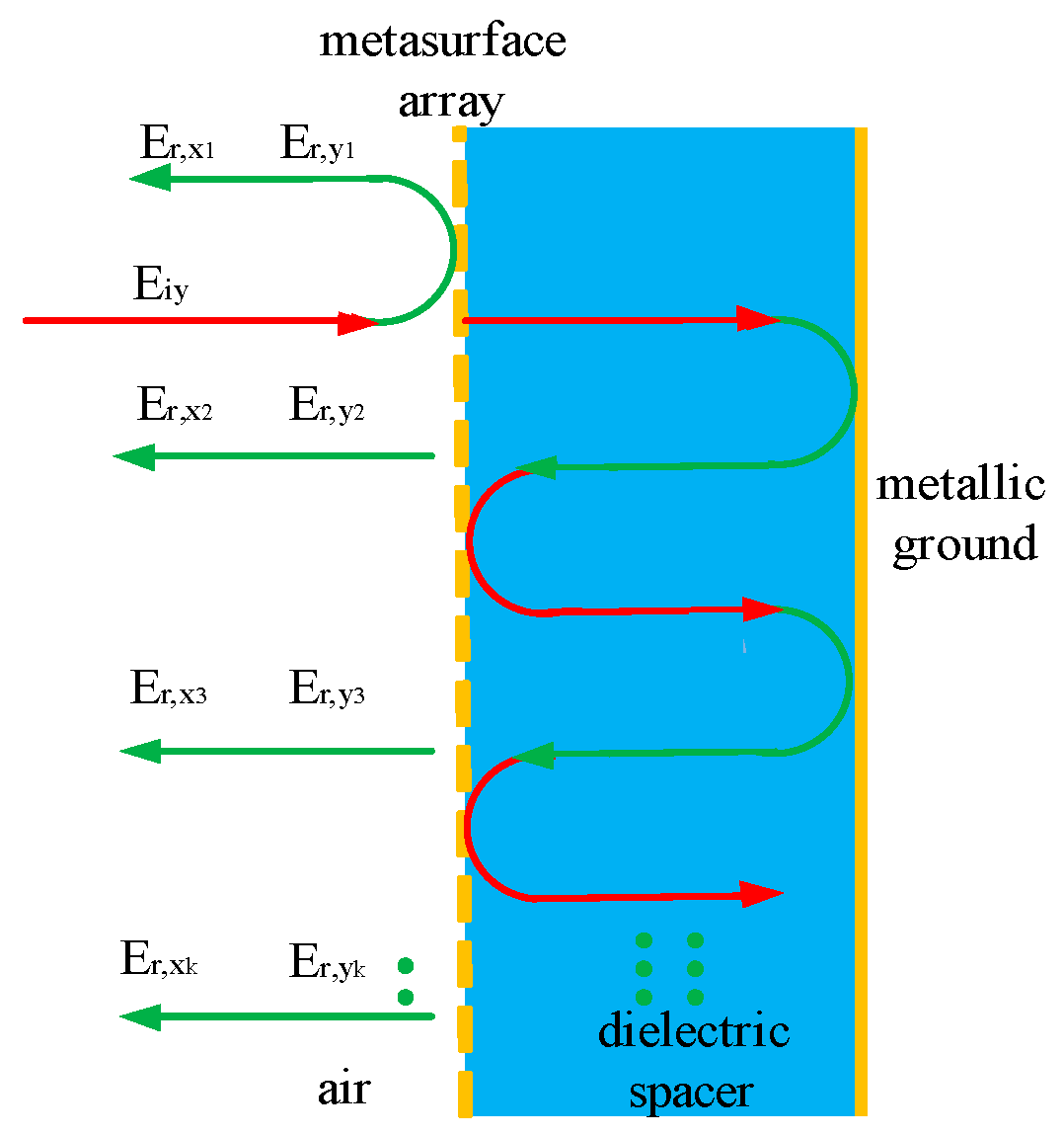
Interference theory can be used to further determine the reasons for the high polarization conversion efficiency. The ground plane and the metasurface array form a Fabry–Pérot-like cavity [51] as illustrated in Figure 5. The incoming electric field is expressed as Eiy; Er,xk and Er,yk (where k is a positive integer) are the kth reflected waves of the cross-polarization and the co-polarization, respectively. Repeated reflections exist for the incoming wave within the dielectric layer. The reflections of the cross-polarization are superimposed uniformly, thereby enhancing the cross-polarized reflection. In contrast, the interference of the co-polarized reflection wave is reduced, leading to reduction in the co-polarized reflection.
The dielectric layer thickness for the reflecting metasurface is also a vital parameter that is closely related to the bandwidth and the PCR. Figure 6a,b show the PCR and the bandwidth for different dielectric layer thicknesses, respectively. As shown in Figure 6b, the PCR first increases and then decreases, while the bandwidth decreases gradually in the first frequency band as the dielectric layer thickness increases. In the second operating band, both the PCR and bandwidth initially increase and then decline with increasing dielectric layer thickness. When the dielectric layer thickness is 3 mm, the maximum PCR value in these two frequency bands is obtained, indicating that the dielectric layer thickness has a significant effect on the PCR. Figure 7 shows the reflection coefficients of the co-polarization ryy for various dielectric layer thicknesses. According to Figure 7, the two resonance frequencies in the first operating band become closer to each other as the dielectric layer thickness increases, leading to a narrower bandwidth in the first band. In contrast, the distance between the two resonant frequencies in the second operating band increases first and then decreases with increasing dielectric layer thickness and the bandwidth is reduced after the initial increase. In addition, ryy in the second operating band increases rapidly as the dielectric layer thickness increases, resulting in a reduction in the PCR. Therefore, when the PCR and the bandwidths of the two operating bands are considered, the dielectric layer thickness can be optimized reasonably well to achieve outstanding dual broadband performance.
Figure 8 illustrates the relationship between the structure parameter θ and the performance of the designed polarization converter. Figure 8a shows that the PCR maintains more than 95% in the whole regulation range. As shown in Figure 8b, there is a red shift in the center frequencies of the two bands. The bandwidth in the first band increases first and then decreases, while the bandwidth in the second band gradually increases with the increase of the θ value. When θ changes from 100° to 130°, the tuning range of the central frequency in the first band is 12.41 to 9.78 GHz and the related relative bandwidth is 28.87–37.14%, while the central frequency of the second band ranges from 18.27 to 15.11 GHz and the relative bandwidth is 25.29–38.12%. Therefore, the designed polarization converter with high polarization conversion efficiency can be adjusted in a wide range, which can greatly materialize the high flexibility and selection for controlling the polarization state of EM waves.
3. Experimental Verification
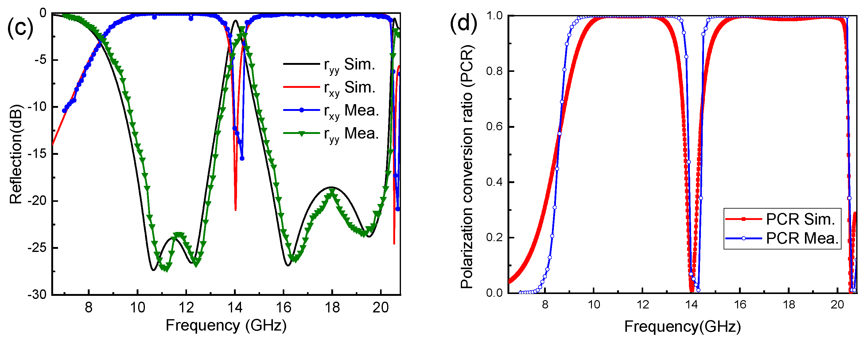
To validate the accuracy of the simulation results, a metasurface sample including 10 × 10 unit cells on an overall scale of 100 × 100 mm2 is fabricated using the printed circuit board (PCB) methods as depicted in Figure 9a. Figure 9b shows that an Agilent N5230A network analyzer is operated in an anechoic chamber to avoid electromagnetic interference. Figure 9c,d display the measured amplitude reflection spectra of the cross-polarization, co-polarization, and PCR, respectively. Figure 9c shows that the measured ryy is less than −10 dB, while rxy is greater than −1 dB in the frequency range from 9.67 to 13.47 GHz. At the same time, two resonant frequencies are present in this frequency range, located at 11.16 and 12.41 GHz. Two more resonant frequencies at 16.49 GHz and 19.26 GHz are present in the second band from 14.96 to 20.45 GHz. The PCR value in these two bands is close to 1. The figures illustrate that the experimental results are highly consistent with the simulated results. Therefore, it is verified that the proposed metasurface can transform y-polarized light into x-polarized light with a high efficiency over a wide band. The following reasons can explain the small differences between the simulation results and experimental results. Firstly, the near-field interactions are neglected in the simulations. Secondly, in the simulation, periodic boundary conditions are adopted, meaning that the structures along the x- and y-directions are infinite, whereas the prepared samples have a finite size. Thirdly, a perfect normally incident electromagnetic wave is used in the simulation, but the device uses a quasi-plane wave which cannot be realized in the experiments.
4. Conclusions
A high-efficiency dual-broadband linear polarization converter based on a reflective metasurface is studied by simulation and experiments. The designed metasurface almost perfectly transform x-polarized or y-polarized incident waves into their mutually perpendicular counterparts in two different bands. Four resonances, which are attributed to the electric and magnetic resonances, emerge in the frequency ranges of 9.38–13.36 GHz and 14.84–20.36 GHz, indicating that the proposed polarization converter has multiple resonance characteristics. In these two bands, the PCR values are greater than 98.21% and 99.32%, respectively. The polarization conversion principle can be explained using the amplitude and phase differences between the incoming and reflected waves and the surface current distributions. Additionally, the effects of the dielectric layer thickness on both the bandwidth and PCR are analyzed. The results show that the bandwidth and PCR of the two frequency bands can be adjusted over a broad range, implying that the manipulation of EM waves is both flexible and selective. The designed dual-broadband and high-efficiency metasurface has great potential in the application of electromagnetic polarization control.
Author Contributions
C.F. put forward the idea, designed the structure, performed the numerical simulations and wrote the article; L.H. analyzed the data; C.L. was in charge of the experiment; Z.S., T.S. and P.K.C. checked the spelling, grammar of this article and put forward some comments.
Funding
This research was funded by the Natural Science Foundation of China (NSFC) (grant No. 51774092 and No. 51474069), Youth Science Foundation of Northeast Petroleum University of China (grant No. 2018QNL-39), Postdoctoral Science Foundation of China (grant No. 2016M601400), and City University of Hong Kong Strategic Research Grant (SRG) (grant No. 7005105).
Conflicts of Interest
The authors declare no conflict of interest.
References
- Xu, J.; Li, R.Q.; Qin, J.; Wang, S.Y.; Han, T.C. Ultra-broadband wide-angle linear polarization converter based on H-shaped metasurface. Opt. Express 2018, 26, 20913–20919. [Google Scholar] [CrossRef] [PubMed]
- Zhang, X.Y.; Duan, W.; Pan, Y.M. Dual-polarized filtering antenna with high selectivity and low cross polarization. IEEE Trans. Antennas Propag. 2018, 64, 4188–4196. [Google Scholar]
- Liu, X.B.; Zhang, J.S.; Li, W.; Lu, R.; Li, L.M.; Xu, Z.; Zhang, A.X. Three-band polarization converter based on reflective metasurface. IEEE Antennas Wirel. Propag. 2017, 16, 924–927. [Google Scholar] [CrossRef]
- Cai, T.; Wang, G.M.; Zhang, X.F.; Shi, J.P. Low-profile compact circularly-polarized antenna based on fractal metasurface and fractal resonator. IEEE Antennas Wirel. Propag. 2015, 14, 1072–1076. [Google Scholar] [CrossRef]
- Wang, F.; Chakrabarty, A.; Minkowski, F.; Sun, K.; Wei, Q.H. Polarization conversion with elliptical patch nanoantennas. Appl. Phys. Lett. 2012, 101, 023101. [Google Scholar] [CrossRef]
- Shi, J.H.; Ma, H.F.; Guan, C.Y.; Wang, Z.P.; Cui, T.J. Broadband chirality and asymmetric transmission in ultrathin 90°-twisted babinet-inverted metasurfaces. Phys. Rev. B 2014, 89, 165128–165135. [Google Scholar] [CrossRef]
- Zang, X.F.; Liu, S.J.; Gong, H.H.; Wang, Y.J.; Zhu, Y.M. Dual-band superposition induced broadband terahertz linear-to-circular polarization converter. J. Opt. Soc. Am. B 2018, 35, 950–957. [Google Scholar] [CrossRef]
- Khan, M.I.; Tahir, F.A. A broadband cross-polarization conversion anisotropic metasurface based on multiple plasmon resonances. Chin. Phys. B 2018, 27, 014101. [Google Scholar] [CrossRef]
- Li, Z.; Liu, W.; Cheng, H.; Chen, S.; Tian, J. Tunable dual-band asymmetric transmission for circularly polarized waves with graphene planar chiral metasurfaces. Opt. Lett. 2016, 41, 3142–3145. [Google Scholar] [CrossRef]
- Syeda, F.J.; Falade, O.P.; Wildsmith, T.; Reip, P.; Alomainy, A. A 60-GHz ultra-thin and flexible metasurface for frequency-selective wireless applications. Appl. Sci. 2019, 9, 945–957. [Google Scholar]
- Xie, Y.Q.; Yang, C.; Wang, Y.; Shen, Y.; Deng, X.H.; Luo, X.Q. The influence of incident modes for polarization conversion in a terahertz metasurface. Opt. Commun. 2019, 435, 341–344. [Google Scholar] [CrossRef]
- Qi, Z.; Guo, C.; Ding, J. Wideband and low RCS circularly polarized slot antenna based on polarization conversion of metasurface for satellite communication application. Microw. Opt. Technol. Lett. 2018, 60, 679–685. [Google Scholar]
- Yurduseven, O.; Marks, D.L.; Fromenteze, T.; Smith, D.R. Dynamically reconfigurable holographic metasurface aperture for a mills-cross monochromatic microwave camera. Opt. Express 2018, 26, 5281–5291. [Google Scholar] [CrossRef] [PubMed]
- Devlin, R.C.; Ambrosio, A.; Rubin, N.A.; Balthasar Mueller, J.P.; Capasso, F. Arbitrary spin-to-orbital angular momentum conversion of light. Science 2017, 358, 896–901. [Google Scholar] [CrossRef]
- Marrucci, L.; Karimi, E.; Slussarenko, S.; Piccirillo, B.; Santamato, E.; Nagali, E.; Sciarrino, F. Spin-to-orbital conversion of the angular momentum of light and its classical and quantum applications. J. Opt. 2011, 13, 064001–064014. [Google Scholar] [CrossRef]
- Sarenac, D.; Cory, D.G.; Nsofini, J.; Hincks, I.; Migue, P.; Arif, M.; Clark, C.W.; Huber, M.G.; Pushin, D.A. Generation of a lattice of Spin-Orbit beams via coherent averaging. Phys. Rev. Lett. 2018, 121, 183602–183608. [Google Scholar] [CrossRef] [PubMed]
- Luu, T.T.; Garg, M.; Kruchinin, S.Y.; Moulet, A.; Hassan, M.T.; Goulielmakis, E. Extreme ultraviolet high-harmonic spectroscopy of solids. Nature 2015, 521, 498–502. [Google Scholar] [CrossRef] [PubMed]
- Gerislioglu, B.; Ahmadivand, A.; Pala, N. Tunable plasmonic toroidal terahertz metamodulator. Phys. Rev. B 2015, 97, 161405. [Google Scholar] [CrossRef]
- Bjarke, T.R.C.; Martin, R.H.; Stefan, A.S.; Westergaard, P.G.; Ye, J.; Holland, M.; Thomsen, J.W. Non-linear Spectroscopy of Sr Atoms in an Optical Cavity for Laser Stabilization. Phys. Rev. A 2015, 92, 053820. [Google Scholar]
- Ahmadivand, A.; Gerislioglu, B. Directional toroidal dipoles driven by oblique poloidal and loop current flows in plasmonic meta-atoms. J. Phys. Chem. C 2018, 122, 24304–24308. [Google Scholar] [CrossRef]
- Meissner, T.; Wentz, F.J. Polarization rotation and the third stokes parameter: The effects of spacecraft attitude and faraday rotation. IEEE Trans. Geosci. Remote Sens. 2006, 44, 506–515. [Google Scholar] [CrossRef]
- Kildishev, A.V.; Boltasseva, A.; Shalaev, V.M. Planar photonics with metasurfaces. Science 2013, 339, 1232009. [Google Scholar] [CrossRef] [PubMed]
- Yu, N.; Capasso, F. Flat optics with designer metasurfaces. Nat. Mater. 2014, 13, 139–150. [Google Scholar] [CrossRef]
- Ahmadivand, A.; Gerislioglu, B.; Pala, N. Large-modulation-depth polarization-sensitive plasmonic toroidal terahertz metamaterial. IEEE Photonics Technol. Lett. 2017, 29, 1860–1863. [Google Scholar] [CrossRef]
- Zhou, Y.; Zhang, G.; Chen, H.; Zhou, P.; Wang, X.; Zhang, L. Design of phase gradient coding metasurfaces for broadband wave modulating. Sci. Rep. 2018, 8, 8672–8680. [Google Scholar] [CrossRef]
- Wu, X.; Yan, M.; Li, W.; Tian, J.; Dai, S.; Wen, W. Anisotropic metasurface with near-unity circular polarization conversion. Appl. Phys. Lett. 2016, 108, 183502–183506. [Google Scholar] [CrossRef]
- Wang, S.; Zhan, Q. Reflection type metasurface designed for high efficiency vectorial field generation. Sci. Rep. 2016, 6, 29626–29637. [Google Scholar] [CrossRef]
- Cong, L.; Srivastava, Y.K.; Singh, R. Inter and intra-metamolecular interaction enabled broadband high-efficiency polarization control in metasurfaces. Appl. Phys. Lett. 2016, 108, 011110. [Google Scholar] [CrossRef]
- Sell, D.; Yang, J.; Wang, E.W.; Phan, T.; Doshay, S.; Fan, J.A. Ultra-high-efficiency anomalous refraction with dielectric metasurfaces. ACS Photonics 2018, 5, 2402–2407. [Google Scholar] [CrossRef]
- Kim, M.; Eleftheriades, G.V. Highly efficient all-dielectric optical tensor impedance metasurfaces for chiral polarization control. Opt. Lett. 2016, 41, 4831–4834. [Google Scholar] [CrossRef]
- Li, Y.; Cao, Q.S.; Wang, Y. A wideband multifunctional multi-layer switchable linear polarization metasurface. IEEE Antennas Wirel. Propag. 2018, 17, 1314–1318. [Google Scholar] [CrossRef]
- Yu, N.F.; Aieta, F.; Genevet, P.; Kats, M.; Gaburro, Z.; Capassp, F. A broadband, background-free quarter-wave plate based on plasmonic metasurfaces. Nano Lett. 2012, 12, 6328–6333. [Google Scholar] [CrossRef] [PubMed]
- Chen, M.; Xiao, X.F.; Chang, L.Z.; Wang, C.Y.; Zhao, D.P. High-efficiency and multi-frequency polarization converters based on grapheme metasurface with twisting double L-shaped unit structure array. Opt. Commun. 2017, 394, 50–55. [Google Scholar] [CrossRef]
- Song, Z.Y.; Zhang, L.; Liu, Q.H. High-efficiency broadband cross polarization converter for near-infrared light based on anisotropic plasmonic metasurfaces. Plasmonics 2016, 11, 61–64. [Google Scholar] [CrossRef]
- Huang, X.J.; Xiao, B.X.; Yang, D.; Yang, H. Ultra-broadband 90° polarization rotator based on bi-anisotropic metamaterial. Opt. Commun. 2015, 338, 416–421. [Google Scholar] [CrossRef]
- Leevesque, Q.; Makhsiyan, M.; Bouchon, P.; Pardo, F. Plasmonic planar antenna for wideband and efficient linear polarization conversion. Appl. Phys. Lett. 2014, 104, 111105. [Google Scholar] [CrossRef]
- Zhao, J.C.; Cheng, Y.Z. A high-effciency and broadband reflective 90° linear polarization rotator based on anisotropic metamaterial. Appl. Phys. B 2016, 122, 255. [Google Scholar] [CrossRef]
- Xu, J.; Li, R.Q.; Wang, S.Y.; Han, T.C. Ultra-broadband linear polarization converter based on anisotropic metasurface. Opt. Express 2018, 26, 26235–26241. [Google Scholar] [CrossRef]
- COMSOL 5.3 Multiphysics Modeling Software. Available online: https://www.comsol.com (accessed on 25 April 2019).
- Liu, Z.; Bai, B.F. Ultra-thin and high-efficiency grapheme metasurface for tunable terahertz wave manipulation. Opt. Express 2017, 25, 8584–8592. [Google Scholar] [CrossRef]
- Sun, H.Y.; Gu, C.Q.; Chen, X.L.; Li, Z.; Liu, L.L.; Martín, F. Ultra-wideband and broad-angle linear polarization conversion metasurface. J. Appl. Phys. 2017, 121, 174902. [Google Scholar] [CrossRef]
- Zheng, Q.; Guo, C.J.; Ding, J. Wideband metasurface-based reflective polarization converter for linear-to-linear and linear-to-circular polarization conversion. IEEE Antennas Wirel. Propag. 2018, 17, 1459–1463. [Google Scholar]
- Yang, D.; Lin, H.; Huang, X. Dual broadband metamaterial polarization converter in microwave regime. Prog. Electromagn. Res. Lett. 2016, 61, 71–76. [Google Scholar] [CrossRef]
- Lin, B.Q.; Wang, B.H.; Meng, W.; Da, X.Y.; Li, W.; Fang, Y.W.; Zhu, Z.H. Dual-band high-efficiency polarization converter using an anisotropic metasurface. J. Appl. Phys. 2016, 119, 183103. [Google Scholar] [CrossRef]
- Liu, Y.J.; Xia, S.; Shi, H.Y.; Zhang, A.X.; Xu, Z. Dual-band and high-efficiency polarization converter based on metasurfaces at microwave frequencies. Appl. Phys. B 2016, 122, 178. [Google Scholar] [CrossRef]
- Zheng, Y.J.; Zhou, Y.L.; Gao, J.; Cao, X.Y.; Yang, H.H.; Li, S.J.; Xu, L.M.; Lan, J.X.; Jidi, L.R. Ultra-wideband polarization conversion metasurface and its application cases for antenna radiation enhancement and scattering suppression. Sci. Rep. 2017, 7, 16137–16149. [Google Scholar] [CrossRef]
- Liu, N.; Guo, H.; Fu, L.; Kaiser, S.; Schweizer, H.; Giessen, H. Plasmon hybridization in stacked cut-wire metamaterials. Adv. Mater. 2007, 19, 3628–3632. [Google Scholar] [CrossRef]
- Jiang, Y.N.; Wang, L.; Wang, J.; Akwuruoha, C.N.; Cao, W.P. Ultra-wideband high-efficiency reflective linear-to-circular polarization converter based on metasurface at terahertz frequencies. Opt. Express 2017, 25, 27616. [Google Scholar] [CrossRef]
- Gao, X.; Han, X.; Cao, W.P.; Li, H.O.; Ma, H.F.; Cui, T.J. Ultra-wideband and high-efficiency linear polarization converter based on double V-shaped metasurface. IEEE Trans. Antennas Propag. 2015, 63, 3522–3530. [Google Scholar] [CrossRef]
- Chen, M.; Sun, W.; Cai, J.J.; Chang, L.Z.; Xiao, X.F. Frequency-tunable mid-infrared cross polarization converters based on grapheme metasurface. Plasmonics 2017, 12, 699–705. [Google Scholar] [CrossRef]
- Grady, N.K.; Heyes, J.E.; Chowdhury, D.R.; Zeng, Y.; Reiten, M.T.; Azad, A.K.; Taylor, A.J.; Dalvit, D.A.R.; Chen, H.T. Terahertz metamaterials for linear polarization conversion and anomalous refraction. Science 2013, 340, 1304–1307. [Google Scholar] [CrossRef]
Figure 1.
Schematic diagram of the designed linear polarization converter (yellow: metal; blue: dielectric spacer material).
Figure 1.
Schematic diagram of the designed linear polarization converter (yellow: metal; blue: dielectric spacer material).

Figure 2.
(a) Simulated cross-polarization (rxy) and co-polarization (ryy) reflections of the designed polarization converter. (b) Spectra of the polarization conversion ratio (PCR) and energy conversion ratio (ECR).
Figure 2.
(a) Simulated cross-polarization (rxy) and co-polarization (ryy) reflections of the designed polarization converter. (b) Spectra of the polarization conversion ratio (PCR) and energy conversion ratio (ECR).

Figure 3.
(a) Definitions of the u- and v-axes, (b) reflected amplitudes of the cross-polarization, (c) reflected amplitudes of the co-polarization, and (d) phase difference of the co-polarization for the electric fields in the u- and v-axis directions.
Figure 3.
(a) Definitions of the u- and v-axes, (b) reflected amplitudes of the cross-polarization, (c) reflected amplitudes of the co-polarization, and (d) phase difference of the co-polarization for the electric fields in the u- and v-axis directions.

Figure 4.
Distributions of the surface currents on the top ((a1)–(a4)) and bottom ((b1)–(b4)) layers of the presented metasurface for the resonance frequencies of 10.67 GHz, 12.22 GHz, 16.18 GHz and 19.51 GHz, respectively.
Figure 4.
Distributions of the surface currents on the top ((a1)–(a4)) and bottom ((b1)–(b4)) layers of the presented metasurface for the resonance frequencies of 10.67 GHz, 12.22 GHz, 16.18 GHz and 19.51 GHz, respectively.

Figure 5.
Schematic diagram of multiple reflections in the Fabry–Pérot-like reflective polarization converter.
Figure 5.
Schematic diagram of multiple reflections in the Fabry–Pérot-like reflective polarization converter.

Figure 6.
(a) PCR for various dielectric layer thicknesses. (b) PCR and bandwidth characteristics for the two frequency ranges with various dielectric layer thicknesses.
Figure 6.
(a) PCR for various dielectric layer thicknesses. (b) PCR and bandwidth characteristics for the two frequency ranges with various dielectric layer thicknesses.

Figure 7.
Reflection coefficients of co-polarization for various dielectric layer thicknesses.

Figure 8.
(a) PCRs with various values of θ. (b) The central frequencies and bandwidths of the two bands corresponding to different values of θ.
Figure 8.
(a) PCRs with various values of θ. (b) The central frequencies and bandwidths of the two bands corresponding to different values of θ.

Figure 9.
(a) Photograph of the prepared sample. (b) Schematic diagram of the measuring device. (c) Experimental and simulated cross- and co-polarized reflections. (d) Polarization conversion ratio.
Figure 9.
(a) Photograph of the prepared sample. (b) Schematic diagram of the measuring device. (c) Experimental and simulated cross- and co-polarized reflections. (d) Polarization conversion ratio.


Table 1.
Comparison of our design with other polarization converters.
| Ref [43] | Ref [44] | Ref [45] | Ref [46] | This Work | |
|---|---|---|---|---|---|
| Operating | 5.50–8.94 | 6.99–9.18 | 11.50–20.0 | 5.1–11.9 | 9.38–13.36 |
| bandwidth (GHz) | 3.10–15.50 | 11.66–20.40 | 28.8–34.0 | --- | 14.84–20.36 |
| Relative bandwidth (%) | 51.19/16.78 | 27.09/54.52 | 53.97/16.56 | 117/-- | 35.00/31.36 |
| PCR (%) | 90/90 | 90/90 | 94/90 | 85/--- | 98.21/99.32 |
© 2019 by the authors. Licensee MDPI, Basel, Switzerland. This article is an open access article distributed under the terms and conditions of the Creative Commons Attribution (CC BY) license (http://creativecommons.org/licenses/by/4.0/).
Share and Cite
MDPI and ACS Style
Fu, C.; Sun, Z.; Han, L.; Liu, C.; Sun, T.; Chu, P.K. High-Efficiency Dual-Frequency Reflective Linear Polarization Converter Based on Metasurface for Microwave Bands. Appl. Sci. 2019, 9, 1910. https://doi.org/10.3390/app9091910
AMA Style
Fu C, Sun Z, Han L, Liu C, Sun T, Chu PK. High-Efficiency Dual-Frequency Reflective Linear Polarization Converter Based on Metasurface for Microwave Bands. Applied Sciences. 2019; 9(9):1910. https://doi.org/10.3390/app9091910
Chicago/Turabian StyleFu, Changfeng, Zhijie Sun, Lianfu Han, Chao Liu, Tao Sun, and Paul K. Chu. 2019. "High-Efficiency Dual-Frequency Reflective Linear Polarization Converter Based on Metasurface for Microwave Bands" Applied Sciences 9, no. 9: 1910. https://doi.org/10.3390/app9091910
Note that from the first issue of 2016, this journal uses article numbers instead of page numbers. See further details here.