An Evaluation of Orbital Angular Momentum Multiplexing Technology

NTT Network Innovation Laboratories, NTT Corporation, 1-1 Hikarinooka, Yokosuka-Shi 239-0847, Japan
*
Author to whom correspondence should be addressed.
Appl. Sci. 2019, 9(9), 1729; https://doi.org/10.3390/app9091729
Submission received: 8 March 2019
/
Revised: 19 April 2019
/
Accepted: 24 April 2019
/
Published: 26 April 2019
(This article belongs to the Special Issue Novel Insights into Orbital Angular Momentum Beams: From Fundamentals, Devices to Applications)
Abstract
:This paper reports our investigation of wireless communication performance obtained using orbital angular momentum (OAM) multiplexing, from theoretical evaluation to experimental study. First, we show how we performed a basic theoretical study on wireless OAM multiplexing performance regarding modulation, demodulation, multiplexing, and demultiplexing. This provided a clear picture of the effects of mode attenuation and gave us insight into the potential and limitations of OAM wireless communications. Then, we expanded our study to experimental evaluation of a dielectric lens and end-to-end wireless transmission on 28 gigahertz frequency bands. To overcome the beam divergence of OAM multiplexing, we propose a combination of multi-input multi-output (MIMO) and OAM technology, named OAM-MIMO multiplexing. We achieved 45 Gbps (gigabits per second) throughput using OAM multiplexing with five OAM modes. We also experimentally demonstrated the effectiveness of the proposed OAM-MIMO multiplexing using a total of 11 OAM modes. Experimental OAM-MIMO multiplexing results reached a new milestone for point-to-point transmission rates when 100 Gbps was achieved at a 10-m transmission distance.
1. Introduction
Recently, wireless communication using OAM (Orbital Angular Momentum) has drawn much attention as an emerging candidate for beyond 5G (fifth generation) technology due to its potential as a means to enable high-speed wireless transmission. OAM is a physical property of electro-magnetic waves that are characterized by a helical phase front in the propagation direction. Since the characteristic can be used to create multiple independent channels, wireless OAM multiplexing can effectively increase the transmission rate in a point-to-point link such as wireless backhaul and/or fronthaul [1,2]. Recent seminar work demonstrated the feasibility of OAM multiplexing by achieving 32 Gbps (gigabits per second) transmission, as Yan et al. reported using the 28 GHz (gigahertz) band in 2014 [1] and the 60 GHz band in 2016 [3]. Since OAM multiplexing technology is relatively new, it is important to validate the feasibility from various perspectives. To do that, we first validated the feasibility from a theoretical perspective using simulations (Section 2). We then validated the feasibility from beam generation and propagation perspectives in experiments (Section 3). Finally, we concluded by validating the feasibility from the end-to-end wireless communication perspective using experiments (Section 4). In our previous research, we explored the potential of wireless OAM multiplexing by conducting the following three studies.
The first part of our work was theoretically investigating the feasibility of OAM multiplexing. First, we investigated the theoretical performance of modulation, demodulation, multiplexing, and demultiplexing OAM algorithms using computer simulations [4]. This enabled us to clarify the performance and effect of mode-dependent power attenuation. In doing so we generated OAM signals by using a UCA (uniform circular array) that comprises multiple omnidirectional antenna elements.
The second part of our work was validating the feasibility from beam generation and propagation perspectives. In particular, we expanded our study to the usage of a dielectric lens to examine the feasibility of long distance transmission using OAM [5]. Ideally, all OAM modes are orthogonal to each other due to the unique nature of their phase fronts. However, with these modes, it is difficult to transmit over long distances because their energy rapidly diverges as the beam propagates. To achieve long-distance transmission, we developed and proposed a beam divergence reduction method using the focusing effect of a dielectric lens. We conducted a wave propagation experiment on 28 GHz bands to demonstrate the effectiveness of using such a lens. In the experiment, we were able to generate OAM modes 0, ±1, and ±2. In addition, we showed the beam divergence reduction effect by making a comparison between conventional OAM beam generation methods and using a dielectric lens with a UCA.
In the third part of our work, we validated the feasibility from the end-to-end wireless communication perspective. We report experimental results using wireless OAM multiplexing at 28 GHz. One of the major challenges for achieving OAM multiplexing is its intensity variation among different OAM modes. As shown in Figure 7, intensity distributions of OAM signals with different modes are given by the Bessel function of the first kind by their inherent nature [2]. This yields selective reception (Rx) SNR (signal-to-noise ratio) degradation when the Rx antenna is located in a low SNR region (null region). To address this problem, we used multiple UCAs, which are designed to avoid reception in null regions. We obtained successful experimental results using five OAM modes over 28 GHz [6]. We also developed and proposed OAM-MIMO multiplexing using multiple UCAs. Unlike OAM multiplexing, OAM-MIMO multiplexing exploits multiple sets of the same OAM modes with receiver equalizations [7]. This enables the number of concurrently transmitted data streams to be increased without using higher OAM modes that have large beam divergence. We experimentally demonstrated the effectiveness of the proposed OAM-MIMO multiplexing by using 11 OAM modes in total (three OAM modes 0 and two sets each of OAM modes ±1 and ±2). Experimental results reached a new milestone in point-to-point transmission rates when 100 Gbps was achieved at 10 m transmission distance.
2. Background and Theoretical Performance Evaluation
2.1. OAM Generation Using a Uniform Circular Array
Studies regarding OAM multiplexing in the wireless communication field are categorized into antenna design and beam generation, end-to-end experiments, signal processing methods, and system studies for topics such as capacity analysis and link budget. Among these, we mainly focus on antenna design in this subsection. Various types of antenna designs have been reported using helicoidally deformed parabolic antennas [8], spiral phase plates (SPP) [2,3,9], holographic plates [10], elaborately tuned planer SPPs [11], and other components [12,13]. In our latest research, we focused on OAM generation using UCAs [14,15,16]. Figure 1 shows OAM mode generation by using UCAs. The phase of each antenna is shifted in accordance with an OAM mode. The transmitted signal from each antenna can be written in vector form as
where L is the OAM mode number and N is the number of radiating antennas in the transmitting UCA. By using a UCA, the OAM state number L is limited by the number of transmitting antennas as |L| < N/2.
Since the diffraction pattern of the UCA can be approximated by the Bessel beam [17], the field distribution of the beam with the OAM mode L is often expressed in the Bessel beam equation as
where , λ, and D, respectively, denote the Lth order Bessel function of the first kind, the wavelength of the carrier frequency, and the radius of the transmitting UCA. Equation (2) is represented in cylindrical coordinates, where and are, respectively, radius and azimuthal angle at the Rx plane that is vertical to the beam propagation direction. is the distance between the centers of the Tx (transmission) and Rx UCAs. Here, let us discuss a comparison between OAM and MIMO. OAM is a specific implementation of MIMO with circular antenna arrays. The difference is that an OAM beam can be achieved virtually and practically in accordance with an OAM state, so it is possible to design a mechanism to manipulate that beam specifically to achieve a specific type of communication. The difference from the conventional MIMO and OAM multiplexing is as follow. To obtain a full rank matrix, usually an NLOS (non-line-of-sight) multipath and a rich scattering environment are assumed in the conventional MIMO. In LOS (line-of-sight) environment cases, digital signal processing such as precoding at the transmitter may be required for the conventional MIMO case to obtain a full rank matrix. On the other hand, OAM does not need digital signal processing at the transmitter to obtain the full rank matrix.
2.2. Modulation and Demodulation
Modulation and demodulation using OAM can be mainly categorized into two schemes. We detail these schemes as follows.
- OAM Shift Keying (OAMSK) [14]: This scheme simply puts binary data into an OAM mode. For example, bit “0” is mapped as OAM mode 1, while bit “1” is mapped as mode -1 (minus 1). OAMSK modulated signals can be demodulated by using the phase gradient method, an FFT (fast Fourier transform) based method, or ML (maximum likelihood) detection. The gradient method uses the phase difference between two receiving antennas to determine the OAM mode. The FFT-based method conducts the FFT process using a reception (Rx) UCA and chooses the maximum coefficients. ML detection selects the OAM mode with the closest distance to the received signal.
- OAM Division Multiplexing (OAMDM) [16]: This scheme uses OAM modes to carry multiple streams of data simultaneously. An OAM mode can carry one stream, similar to the way that one OFDM (orthogonal frequency division multiplexing) subcarrier can. This scheme potentially improves the spectrum efficiency. With it, OAMDM modulated signals are demodulated similar to the way they are with MIMO equalization techniques such as zero forcing or minimum mean square error equalization, assuming the channel information is available. Since OAM multiplexing is expected to be used under LOS environments with static channels such as wireless fronthaul/backhaul, simplified channel estimation using Equation (2) might be feasible.
2.3. Mode-Dependent Power Distribution
In the work we report here, we also considered two key issues regarding the mode-dependent power distribution among different OAM modes. These issues are as follows.
- Peak Rx Power Degradation: As the number of OAM modes increases, the radiation becomes wider, the angle from the beam axis at the peak Rx power becomes wider, and the SNR at its peak Rx power becomes smaller. Accordingly, the performance is degraded as the number of OAM modes increases.
- Non-identical Peak Rx Power Locations: The peak Rx power locations of each OAM mode are not identical because their radiation patterns are distinct. Therefore, the mode-dependent performance degradation becomes more severe when a single Rx UCA is used because some OAM modes might not have the peak Rx power at a certain location.
2.4. Evaluation
We implemented a simulation testbed of OAM based wireless communication at 60 GHz. Figure 1 shows an illustration of the generation of OAM signals using UCA. The gain for each antenna element reflects the UCA as set to be 0 dBi (decibels relative to isotropic radiator). Note that concurrent transmission of multiple OAM modes can be achieved by superposing multiple OAM signals. It is generally assumed that OAM multiplexing is to be mainly used in LOS environments such as wireless fronthaul and/or backhaul. Therefore, we used an AWGN (additive white Gaussian noise) channel environment.
Figure 2a shows the OAMSK performance obtained by the phase gradient method, which uses two antennas for OAM signal detection with varying Rx array radius and angular distance between two Rx antenna elements. Although the performance is poorer than that obtained with FFT-based and ML methods, only two antenna elements are necessary. This is in contrast to cases in which all the Rx UCA elements are required. This is favorable for higher OAM mode transmission. Figure 2b shows the OAMSK performance obtained by using the FFT-based method and ML detection while varying the number of antenna components in the Rx UCA. We found that in both cases the ML detection yields generally better results and additional performance gain is achieved as the number of antenna components in the Rx UCA increases. Figure 2c shows the OAMDM performance with fixed total Rx power among OAM modes. Note that Rx signals in this curve are obtained at the location of the peak Rx power of each mode. In this case, we observed performance degradation of 3 dB as the number of OAM modes increased. Figure 2d shows the effect of a non-identical location of the peak Rx power by varying the Rx array radius. As the OAM mode number increases, the Rx array radius for the best BER (bit error rate) performance also increases. Correspondingly, if the Rx array radius is customized for a certain OAM mode, the performance of other OAM modes’ signals might be deteriorated severely. For this, multiple UCAs might be necessary, which leads us to use multiple UCAs.
In this subsection, we report how we studied the potential and limitations of OAM-based wireless communication in terms of mode-dependent power attenuation and non-identical peak Rx power locations through the use of modulation and demodulation algorithms. We confirmed the effect of mode-dependent performance variations. Further study is necessary to fully rectify the undesirable effects of the mode-dependent power attenuation.
3. Beam Focusing Effect Using Dielectric Lens for OAM Multiplexing
3.1. Usage of Dielectric Lens for OAM Multiplexing
We present the beam focusing effect obtained by using a dielectric lens for OAM multiplexing to increase the transmission distance. Figure 3 shows the configuration of the transmitting and receiving antennas. The OAM mode radiates from the UCA installed on the back of the dielectric lens. The OAM mode radiated into the space is phase-modulated by the lens and reaches the reception point. When transmitting the OAM mode n, we weight each element of the array antenna. Since the phase distribution in the OAM mode is circularly symmetric in the plane perpendicular to the beam traveling direction, a circular lens is used so that circular symmetry is not disturbed by phase modulation at the time of passing through the lens.
By properly setting focal length f of the lens considering the distance between the lens and the transmitting antenna, the beam can be narrowed by the light converging effect. For example, Fukumoto et al. [4,18] showed that the beam spread can be reduced based on the imaging magnification at the reception point.
3.2. Experiments of OAM Multiplexing Using Dielectric Lens
To confirm the basic operation produced in using a dielectric lens, we performed a propagation experiment using the 28 GHz band in an anechoic chamber. Figure 4 shows the experimental setup. The measurement frequency of the network analyzer (NWA) was set from 2 to 3 GHz. Radio frequency (RF) chains up-converted 28–29 GHz inserted signals and fed them to the Tx antenna. At the receiver side, the received signals were down-converted to 2–3 GHz signals by the RF chains attached directly after the Rx antenna. We used a millimeter wave commercial lens whose directional gain and beam half-width were, respectively, 35 dBi and 3 cm (centimeters). The design requirements for dielectric lenses, including focal length, refractive index, diameter, directional gain, and beam half-width, remain open for analysis.
In the propagation measurements, we measured the channel coefficient between the Tx and Rx antennas using NWA while operating the positioner to move the Tx and Rx antennas to form the Tx and Rx UCAs elements’ location sequentially. In other words, we emulated Tx and Rx UCAs using a single Tx and Rx antenna by sequentially measuring the channel coefficients of two points and combined the entire measurements to obtain channel characteristics between the emulated Tx and Rx antennas. The gain for both Tx and Rx antennas element was 27 dBi. We obtained M × N channel matrix H with measured channel coefficients consisting of all combinations between N-points (Tx side) and M-points (Rx side). Subsequently, we performed a matrix operation corresponding to OAM mode generation on the measured channel matrix and evaluated the phase and intensity distributions. The amplitude and phase characteristics of the OAM mode n were obtained by multiplying the column vector that generates OAM mode n by obtained channel matrix H.
Table 1 shows experimental parameters. First, to confirm that an OAM mode was generated at the Rx side, we measured the phase distribution and the intensity distribution formed by the beam passing through the lens on the Rx side.
Figure 5 shows the measurement results and simulation results of the intensity distribution and phase distribution of OAM modes −2, −1, 0, +1, and +2. The measurements were conducted over a 60 cm × 60 cm grid and data were acquired at 3 cm intervals. The figure results confirmed that OAM beams whose phases rotate as much as their mode order were obtained in the experiments. The results also well matched the simulation results. Further, we consider that our experimental method will make it possible to emulate OAM beam generation.
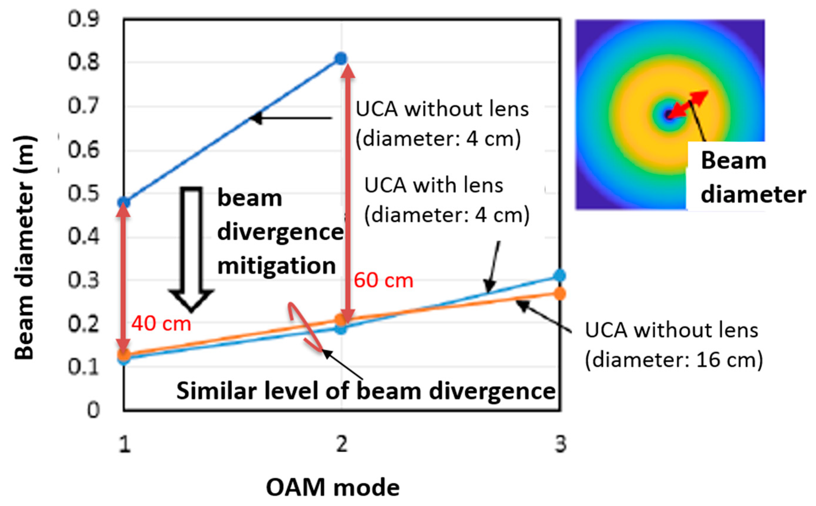
Next, we conducted experiments to ascertain the beam divergence reduction effect obtained with the lens. We took into account the distance from the center of the Rx side to the location of the strongest beam intensity since it is the quantitative index for evaluating beam divergence. We defined this metric as the beam diameter. The smaller is the beam diameter, the smaller is the beam divergence at the Rx side because the beam energy is more focused close to the center of the Rx antenna. Figure 6 shows comparisons between a UCA with a 4 cm diameter, a UCA with a 16 cm diameter, and a UCA with a 4 cm diameter plus a 16 cm lens.
The beam diameters of the UCA with a lens in modes 1 and 2 were, respectively, 40 and 60 cm smaller than that of a UCA having a 4 cm diameter without a lens. We also found that the beam diameter of the UCA with a lens was in good agreement with the beam diameter of a UCA with a 16 cm diameter. These results enabled us to confirm that the beam divergence can be reduced by using a dielectric lens and that the transmission distance can be correspondingly increased. Experimental results also showed that a UCA with a 4 cm diameter and a lens produced an OAM beam similar to that produced by a UCA with a 16 cm diameter. These results suggested that using a dielectric lens is one of the options that will enable OAM wireless multiplexing systems to effectively address the beam divergence.
4. Experimental Demonstration Wireless OAM Multiplexing Technology using 28 GHz
4.1. OAM Multiplexing Using Multiple UCAs
The intensity distributions of OAM signals with different modes are given by the Bessel function of the first kind by their inherent nature, as shown in Figure 7. This yields a selective degradation when the Rx antenna is located in a low SNR region. To address this problem, we used multiple UCAs, which are designed to avoid reception in null regions. In this subsection, we first describe successful experimental results we obtained using five OAM modes over 28 GHz.
We used multiple UCAs for both Tx and Rx antennas to rectify mode-selective Rx SNR degradation. Figure 8 shows our antenna design. It consists of four UCAs with different radii and a single antenna in the center. Each UCA consists of 16 antenna elements. The gain for each antenna element in each UCA was 11 dBi. The antenna in the center (hereafter UCA No. 0 for notation convenience) is used for the axis alignment and transmission of OAM mode 0. We used the following two methods to choose different UCAs for different OAM modes’ transmission and chose Rx UCAs.
- Antenna Selection: Selecting a single Rx UCA that is not located at the null region of each OAM mode
- Receiver Diversity: Selecting multiple Rx UCAs to obtain Rx SNR enhancement by receiver diversity
4.2. OAM-MIMO Multiplexing Using Multiple UCAs
This subsection presents wireless OAM-MIMO multiplexing that combines the OAM and MIMO concepts. The number of usable OAM modes is limited due to their mode-dependent beam divergence. In particular, higher OAM modes have a practical limitation due to their nature of large attenuation caused by beam divergence. To address this problem, we present OAM-MIMO multiplexing using multiple UCAs. Unlike OAM multiplexing, OAM-MIMO multiplexing exploits multiple sets of the same OAM modes with receiver equalizations. Consequently, the number of concurrently transmitted data streams can be increased without using higher OAM modes that have large beam divergence.
To enable OAM-MIMO multiplexing, we also used multiple UCAs such as OAM multiplexing. To achieve superposition-based simultaneous OAM beam generation and separation, we, respectively, implemented wideband analog 5 × 16 and 16 × 5 Butler matrices for Tx and Rx UCAs.
4.3. Experimental OAM Multiplexing Results Using Multiple UCAs
We conducted wireless OAM multiplexing experiments using five different OAM modes (−2, −1, 0, 1, and 2) over 28 GHz. Detailed descriptions regarding experimental parameters are given in Table 2.
We used the single carrier with frequency domain equalization (SC-FDE) to average channel characteristics over a wide signal bandwidth. The signal bandwidth was 2 GHz and 64-QAM modulation was used for all five OAM modes. The transmission rate per single stream was 9 Gbps. Experiments were conducted in a shielded room, as shown in Figure 9. The distance between Tx and Rx antennas was 2.5 m. The propagation loss can be calculated with Equation (2) with UCA sizes and distance between Tx and Rx. Tx signals were generated by arbitrary waveform generators and fed into a Tx antenna. The Rx antenna received signals and fed them into a digital oscilloscope that worked as an analog-to-digital convertor. Since the digital oscilloscope is equipped with four ports, reception was done sequentially using the four ports. This is not significant since the channel environments was static in the shield room. Offline digital signal processing was conducted using all the converted signals.
Table 3 shows the experimental results we obtained for two methods. For both antenna selection and receiver diversity, we, respectively, used UCA No. 4, UCA No. 2, UCA No. 0, UCA No. 3, and UCA No. 1 for transmitting OAM modes −2, −1, 0, +1, and +2 signals. For the antenna selection method, we selected UCA No. 3, UCA No. 4, UCA No. 0, UCA No. 3, and UCA No. 1. By applying the LDPC channel coding (rate 3/4), we confirmed that error-free transmissions were obtained except for the OAM mode 2 case. For the receiver diversity method, we, respectively, selected UCA No. 4 and UCA No. 2 for OAM modes −1 and +2. We were able to confirm that error-free transmissions were received in all OAM modes with the same LDPC channel coding in this case. Using 2 GHz of signal bandwidth yielded a 45 Gbps transmission rate.
4.4. Experimental OAM-MIMO Multiplexing Results Using Multiple UCAs
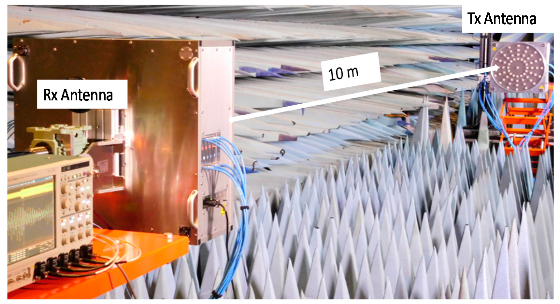
We conducted experiments on the OAM-MIMO multiplexing using our implemented antennas. Figure 10 and Table 4 show the experimental setup and parameters. Tx signals were generated by offline digital signal processing and fed into our implemented Tx antenna. Outputs of the Rx signals were fed into a digital oscilloscope that worked as an analog-to-digital convertor as in the OAM multiplexing experiments. In these experiments, the digital oscilloscope was equipped with four ports and reception was done sequentially using the ports. This also did not significantly affect the results since the channel environments were static in the shield room as in the OAM multiplexing experiments.
We used eleven streams for the OAM-MIMO multiplexing experiment. Two Tx UCAs (UCA No. 1 and No. 4), respectively, transmitted five OAM modes (0, ±1, ±2) and UCA No. 0 transmitted OAM mode 0. We used the received signals of all Rx UCAs for the equalization. Table 5 summarizes the modulations, channel coding rates and corresponding transmission rates used in the experiment. The propagation loss was calculated with Equation (2) with UCA sizes and distance between Tx and Rx. We confirmed that successful error-free transmissions were obtained in all streams with the usage of the forward error correction. Total transmission rate was 100 Gbps at a 10 m transmission distance. The results indicated a new milestone was reached in terms of point-to-point wireless transmission. In addition, we recently extended our work by extending the baseband signal processing to successfully achieve 120 Gbit/s using a total of 11 OAM modes [19]. This is the state-of-the-art results that have been published in the literature.
5. Conclusions
In this paper, we describe how we investigated wireless orbital angular momentum (OAM) multiplexing performance from theory to experimental perspectives. First, we conducted basic theoretical studies on wireless OAM multiplexing performance with respect to various aspects including modulation, demodulation, multiplexing, and demultiplexing. Then, we expanded our interest to experimental evaluation including a dielectric lens and end-to-end wireless transmission at 28 GHz frequency bands. We confirmed that using a dielectric lens can effectively reduce the beam divergence effect and correspondingly increase the transmission distance. In end-to-end experiments, we achieved 45 Gbps throughput using five OAM modes. In addition, we experimentally demonstrated the effectiveness of our proposed OAM-MIMO multiplexing method using a total of 11 OAM modes. In the experiments, we reached a new milestone in point-to-point transmission rates by achieving 100 Gbps at a 10 m transmission distance.
Author Contributions
D.L. and H.S. contributed to conceptualization and methodology, H.S. and H.F. conducted validation, D.L., H.S., H.F. and Y.Y. conducted data curation, D.L. contributed to writing original draft preparation and editing, T.S. supervised overall work.
Funding
This research received no external funding.
Conflicts of Interest
The authors declare no conflict of interest.
References
- Yan, Y.; Xie, G.; Lavery, M.P.J.; Huang, H.; Ahmed, N.; Bao, C.; Ren, Y.; Cao, Y.; Li, L.; Zhao, Z.; et al. High-capacity millimeter-wave communications with orbital angular momentum multiplexing. Nat. Commun. 2014, 5, 4876. [Google Scholar] [CrossRef] [PubMed]
- Lee, D.; Sasaki, H.; Fukumoto, H.; Hiraga, K.; Nakagawa, T. Orbital Angular Momentum (OAM) Multiplexing: An Enabler of a New Era of wireless Communications. IEICE Trans. Commun. 2017, E100-B, 1044–1063. [Google Scholar] [CrossRef]
- Yan, Y.; Li, L.; Zhao, Z.; Xie, G.; Wang, Z.; Ren, Y.; Ahmed, N.; Sajuyigbe, S.; Talwar, S.; Tur, M.; et al. 32-Gbit/s 60-GHz millimeter-wave wireless communication using orbital angular momentum and polarization multiplexing. In Proceedings of the 2016 IEEE International Conference on Communications (ICC), Kuala Lumpur, Malaysia, 22–27 May 2016; pp. 1–6. [Google Scholar]
- Lee, D.; Sakdejayont, T.; Sasaki, H.; Fukumoto, H.; Nakagawa, T. Performance evaluation of wireless communications using orbital angular momentum multiplexing. In Proceedings of the 2016 International Symposium on Antennas and Propagation (ISAP), Okinawa, Japan, 24–28 October 2016. [Google Scholar]
- Fukumoto, H.; Lee, D.; Sasaki, H.; Kaho, T.; Shiba, H. An experimental study on beam focusing effect using dielectric lens for OAM multiplexing. IEICE Tech. Rep. 2018, 117, 53–57. [Google Scholar]
- Lee, D.; Sasaki, H.; Fukumoto, H.; Yagi, Y.; Kaho, T.; Shiba, H.; Shimizu, T. Demonstration of an orbital angular momentum (OAM) multiplexing at 28 GHz. IEICE General Conf. 2018, B-5-90. [Google Scholar]
- Lee, D.; Sasaki, H.; Fukumoto, H.; Yagi, Y.; Kaho, T.; Shiba, H.; Shimizu, T. An experimental demonstration of 28 GHz band wireless OAM-MIMO (orbital angular momentum multi-input multi-output) multiplexing. In Proceedings of the IEEE 87th Vehicular Technology Conference (VTC Spring), Porto, Portugal, 3–6 June 2018. [Google Scholar]
- Mari, E.; Spinello, F.; Oldoni, M.; Ravanelli, R.A.; Romanato, F.; Giuseppe, F.; Parisi, G. Near-field experimental verification of separation of OAM channels. IEEE Antennas Wirel. Propag. Lett. 2015, 14, 556–558. [Google Scholar] [CrossRef]
- Willner, A.E. Communication with a twist. IEEE Spectrum 2016, 53, 34–39. [Google Scholar] [CrossRef]
- Mahmouli, F.E.; Walker, S.D. 4Gbps uncompressed video transmission over a 60-GHz orbital angular momentum wireless channel. IEEE Wirel. Commun. Lett. 2013, 2, 223–226. [Google Scholar] [CrossRef]
- Cheng, L.; Hong, W.; Hao, Z. Generation of electromagnetic waves with arbitrary orbital angular momentum modes. Scientific Rep. 2014, 4, 4814. [Google Scholar] [CrossRef] [PubMed]
- Jin, J.; Luo, J.; Zhang, X.; Gao, H.; Li, X.; Pu, M.; Gao, P.; Zhao, Z.; Lou, X. Generation and detection of orbital angular momentum via metasurface. Scientific Rep. 2016, 6, 24286. [Google Scholar] [CrossRef] [PubMed] [Green Version]
- Deng, C.; Chen, W.; Zhang, Z.; Li, Y.; Feng, Z. Generation of OAM Radio Waves Using Circular Vivaldi Antenna Array. Int. J. Antennas Propag. 2013, 2013, 1–7. [Google Scholar] [CrossRef]
- Haskou, A.; Mary, P.; Hélard, M. Error probability on the orbital angular momentum detection. In Proceedings of the 2014 IEEE 25th Annual International Symposium on Personal, Indoor, and Mobile Radio Communication (PIMRC), Washington, DC, USA, 2–5 September 2014; pp. 302–307. [Google Scholar]
- Opare, K.A.; Kuang, Y.; Kponyo, J.J.; Nwizege, K.S.; Enzhan, Z. The degree of freedom in wireless line-of-sight OAM multiplexing system using a circular array of receiving antenna. In Proceedings of the 2015 Fifth International Conference on Advanced Computing & Communication Technologies, Rohtak, Haryana, India, 21–22 February 2015. [Google Scholar]
- Opare, K.A.; Kuang, Y.; Kponyo, J.J.; Nwizege, K.S.; Enzhan, Z. Mode combination in an ideal wireless OAM-MIMO multiplexing system. IEEE Wirel. Commun. Lett. 2015, 4, 449–452. [Google Scholar] [CrossRef]
- Tian, H.; Liu, Z.; Xi, W.; Nie, G.; Liu, L.; Jiang, H. Beam axis detection and alignment for uniform circular array-based orbital angular momentum wireless communication. IET Commun. 2016, 10, 44–49. [Google Scholar] [CrossRef]
- Fukumoto, H.; Lee, D.; Sasaki, T.; Nakagawa, T. Beam divergence reduction using dielectric lens for orbital angular momentum based wireless communications. In Proceedings of the 2016 International Symposium on Antennas and Propagation (ISAP), Okinawa, Japan, 24–28 October 2016. [Google Scholar]
- Sasaki, H.; Lee, D.; Fukumoto, H.; Yagi, Y.; Kaho, T.; Shiba, H.; Shimizu, T. Experiment on Over-100-Gbps Wireless Transmission with OAM-MIMO Multiplexing System in 28-GHz Band. In Proceedings of the 2018 IEEE Global Communications Conference (GLOBECOM), Abu Dhabi, United Arab Emirates, 9–13 December 2018. [Google Scholar]
Figure 1.
Generation of OAM modes by a uniform circular array.

Figure 2.
Performance evaluations of: (a) OAMSK (phased gradient method with varying Rx array radius); (b) OAMSK (FFT-based and ML methods); (c) OAMDM with fixed Rx power; and (d) OAMDM with varying Rx array radius.
Figure 2.
Performance evaluations of: (a) OAMSK (phased gradient method with varying Rx array radius); (b) OAMSK (FFT-based and ML methods); (c) OAMDM with fixed Rx power; and (d) OAMDM with varying Rx array radius.

Figure 3.
Configuration of the Tx and Rx antennas using dielectric lens.

Figure 4.
Experimental environment (OAM multiplexing using dielectric lens).

Figure 5.
Measurement results and simulation results of phase and intensity distributions.

Figure 6.
Experimental beam diameter results.

Figure 7.
Bessel distributions of Rx signals.

Figure 8.
Implemented multiple uniform circular arrays (Four UCAs and a center antenna).

Figure 9.
Experimental environment (OAM multiplexing).

Figure 10.
Experimental environment (OAM-MIMO multiplexing).


Table 1.
Experimental parameters (Dielectric lens).
| Parameter | Value | |
|---|---|---|
| Lens | Focal length: f | 0.30 m |
| Diameter: DL | 0.30 m | |
| UCA | Number of antenna elements | 12 |
| Diameter: DT | 0.04 m | |
| Distance between lens and UCA: a | 0.40 m | |
| Others | Frequency | 28 GHz |
| Distance between Tx and Rx: b | 3.12 m | |
Table 2.
Experimental parameters (OAM multiplexing).
| Parameter | Value | Parameter | Value |
|---|---|---|---|
| Center frequency | 28.5 GHz | OAM modes | −2, −1, 0, 1, 2 |
| Signal bandwidth | 2 GHz | Number of streams | 5 |
| Number of UCAs | 4 | Signal carrier | Single carrier |
| Number of antenna elements in a UCA | 16 | Modulation | 64 QAM *1 |
| Number of antenna elements | 65 | Channel coding | LDPC (DVB-S2) 3/4 |
| Diameter of UCA | 24, 26, 48, 60 cm | Equalization | Frequency domain equalization |
| Tx/Rx distance | 2.5 m | Block size | 256 |
*1 T quadrature amplitude modulation, *2 low density parity check, *3 digital video broadcasting satellite second generation.
Table 4.
Experimental parameters (OAM-MIMO multiplexing).
| Parameter | Value | Parameter | Value |
|---|---|---|---|
| Center frequency | 28.5 GHz | OAM modes | −2, −1, 0, 1, 2 |
| Signal bandwidth | 2 GHz | Number of streams | 11 |
| Number of UCAs | 4 | Signal carrier | Single carrier |
| Number of antenna elements in a UCA | 16 | Modulation | 16 QAM/64 QAM |
| Number of antenna elements | 65 | Channel coding | LDPC (DVB-S2) 3/4, 5/6, 9/10 |
| Diameter of UCA | 24, 26, 48, 60 cm | Equalization | Freq. domain equalization |
| Tx/Rx distance | 10 m | Block size | 256 |
Table 5.
Experimental results (OAM-MIMO multiplexing).

Table 3.
Experimental results (OAM multiplexing).
| Mode −2 | Mode −1 | Mode 0 | Mode +1 | Mode +2 | ||
|---|---|---|---|---|---|---|
| Antenna selection | Tx antenna | UCA No. 4 | UCA No. 2 | UCA No. 0 | UCA No. 3 | UCA No. 1 |
| Rx antenna | UCA No. 3 | UCA No. 4 | UCA No. 0 | UCA No. 3 | UCA No. 1 | |
| BER (raw) | 0.0114 | 0.0228 | 0.0201 | 0.0192 | 0.0428 | |
| BER (coded) | 0.0000 | 0.0000 | 0.0000 | 0.0000 | 0.0024 | |
| Receiver diversity | Tx antenna | UCA No. 4 | UCA No. 2 | UCA No. 0 | UCA No. 3 | UCA No. 1 |
| Rx antenna | UCA No. 3 | UCA No. 2, No. 4 | UCA No. 0 | UCA No. 3 | UCA No. 1, No. 2 | |
| BER (raw) | 0.0105 | 0.0015 | 0.0022 | 0.0278 | 0.0385 | |
| BER (coded) | 0.0000 | 0.0000 | 0.0000 | 0.0000 | 0.0000 |
© 2019 by the authors. Licensee MDPI, Basel, Switzerland. This article is an open access article distributed under the terms and conditions of the Creative Commons Attribution (CC BY) license (http://creativecommons.org/licenses/by/4.0/).
Share and Cite
MDPI and ACS Style
Lee, D.; Sasaki, H.; Fukumoto, H.; Yagi, Y.; Shimizu, T. An Evaluation of Orbital Angular Momentum Multiplexing Technology. Appl. Sci. 2019, 9, 1729. https://doi.org/10.3390/app9091729
AMA Style
Lee D, Sasaki H, Fukumoto H, Yagi Y, Shimizu T. An Evaluation of Orbital Angular Momentum Multiplexing Technology. Applied Sciences. 2019; 9(9):1729. https://doi.org/10.3390/app9091729
Chicago/Turabian StyleLee, Doohwan, Hirofumi Sasaki, Hiroyuki Fukumoto, Yasunori Yagi, and Takashi Shimizu. 2019. "An Evaluation of Orbital Angular Momentum Multiplexing Technology" Applied Sciences 9, no. 9: 1729. https://doi.org/10.3390/app9091729
Note that from the first issue of 2016, this journal uses article numbers instead of page numbers. See further details here.