Fabrication of ZrO2(MgO)/CaAl2O4+CaAl4O7 Bilayer Structure Used for Sulfur Sensor by Laser Cladding


School of Metallurgy, Northeastern University, Shenyang 110819, China
*
Author to whom correspondence should be addressed.
Appl. Sci. 2019, 9(6), 1036; https://doi.org/10.3390/app9061036
Submission received: 2 January 2019
/
Revised: 8 March 2019
/
Accepted: 8 March 2019
/
Published: 13 March 2019
(This article belongs to the Special Issue Ceramic Composites and Films)
Abstract
:The ZrO2(MgO)/CaAl2O4+CaAl4O7 bilayer structure used for sulfur sensor was fabricated by the laser powder cladding (LPC) method using the MgO partially stabilized zirconia (2.7 wt% MgO-PSZ) as the substrate and the CaAl2O4 + CaAl4O7 composites as the coating material. The microstructure, phase composition and ionic conductivity of this bilayer structure were investigated for better application in the sulfur determination. The results indicated that the structure of the coating was dense and well-distributed with a thickness of 100 μm. The ionic conductivity of the ZrO2(MgO)/CaAl2O4+CaAl4O7 bilayer structure was up to 2.06 × 10⁻³ S·cm−1 at 850 °C that met the required ionic conductivity of ionic conductor for solid electrolyte sulfur sensor. Furthermore, the sulfur sensor Mo|Cr+Cr2O3| ZrO2(MgO)| CaAl2O4+CaAl4O7|[S]Fe| Mo was assembled used this bilayer structure and tested in carbon-saturated liquid iron at 1773 K and 1823 K. The stability and reproducibility of the sulfur sensor were satisfactory and could be used for sulfur determination in the liquid iron.
1. Introduction
In the iron and steel metallurgical industry, on-line measurement of sulfur in liquid iron and steel has been a challenge for decades and two types of sulfur sensors have developed. One is the direct sulfur determination sensor by sulfide solid electrolyte [1,2,3,4,5], the other is the indirect sulfur sensor based on ZrO2 with doped oxides and β-Al2O3 as solid electrolyte and sulfides as auxiliary electrode [6,7,8,9,10,11]. However, all the above sulfur sensors have as a common characteristic that the solid electrolyte used for the sulfur sensor contains sulfides. Owing to the thermal instability of sulfides at high temperature, the solid electrolyte used for the sulfur sensor is much more difficult to fabricate. Moreover, due to the poor thermal stability of this electrolyte, it cannot be preserved for a long time, and the repeated preparation process greatly increases the consumption of manpower and material resources, and thus increases the production cost. Hence, a sulfur sensor that meets the requirements of the production has not been successfully fabricated by the above methods. Therefore, developing a novel sulfur sensor for sulfur determination is pressing.
It is generally known that calcium aluminates are attractive ceramic materials for high-temperature refractory applications and also play important roles in the steel industry as desulfurizing agents. Calcium aluminate can react rapidly with sulfur in the liquid iron to form calcium sulfide attached to its surface, and then calcium sulfide and calcium oxide come to equilibrium as the reaction is prolonged [12,13,14]. Therefore, if the calcium aluminate is coated on the surface of the solid electrolyte to form a bilayer structure, the calcium sulfide would be formed on the side of the calcium aluminate coating when inserted into the liquid iron, and furthermore the calcium sulfide could work as the same function as the traditional auxiliary electrode. The aforementioned electrolyte could be kept for a long time and could be prepared in sufficient quantities for further processes, which could make the production process more complete and reduce unnecessary consumption.
The thermodynamics of the sulfur determination using the bilayer system in the liquid iron can be written as follows.
where K is the equilibrium constant, a[S] and a[O] are the activities of [S] and [O] in the liquid iron, respectively, does not change with the sulfur content and it can be considered to be a constant value. Wen et al. [15] have analyzed the relationship between the CaS and CaO incorporated in CaAl2O4 and CaAl4O7 in liquid iron, and found that a[O] was very low in the carbon-saturated liquid iron. It should be noted that the effect of other elements in molten iron on reaction (1) should be eliminated for ensure its occurrence, such as the element P. Therefore, the purity of liquid iron for testing should be high, and the trace elements such as P and Si elements containing in the liquid iron should be less and would not have any effect on the reaction (1) in this stage. The effect of other elements on the reaction would be examined in the next study. Under these conditions, when the sulfur content was significantly higher than the oxygen content (for example 0.02–0.1 wt% S), the equilibrium of reaction (1) would proceed to the right to form CaS used as the auxiliary electrode and eventually the [S] and [O] would come to equilibrium at the phase boundary of the auxiliary electrode and the liquid iron. Then the electromotive force (EMF) would be obtained and the sulfur content could be calculated from the following equation.
where E is the EMF of the sulfur sensor (V), T is the temperature of the molten iron (K).
Based on the above principle, a bilayer structure of non-sulfide solid electrolyte with a coating of calcium aluminate has been proposed to use in the sulfur sensor, as this unique structure would solved the disadvantages of the traditional sulfide coating with poor stability and easy oxidation. Meanwhile, this structure would also help more effectively to increase the conductivity in the sensor and avoid high electronic conductivity. The traditional methods of producing this bilayer structure is by coating the desired layer of material either by plasma spraying, flame spraying, or screen printing [6,8,9]. However, the disadvantages of these methods are that the coating may contain pinholes, and can fall off easily due to erosion of the liquid iron.
In this paper, an attempt has been made to fabricate the ZrO2(MgO)/CaAl2O4+CaAl4O7 bilayer system used for sulfur sensor by using the laser powder cladding (LPC) method. The properties of this structure in terms of the microstructure, composition and the ionic conductivity were investigated. The application of the bilayer structure in sulfur determination was also studied.
2. Experimental
2.1. Fabrication of the ZrO2(MgO)/CaAl2O4+CaAl4O7 Bilayer Structure
The CaAl2O4+CaAl4O7 powder containing 40 wt% of CaO in this term as the coating material was synthesized by a chemical method from Al(NO3)3∙9H2O and Ca(NO3)2∙4H2O. The commercial ZrO2(MgO) electrolyte tube (Wuhan Huafeng Sensor Apparatus Co., LtD, Wuhan, China) was used as the substrate. Then the CaAl2O4+CaAl4O7 powder obtained was layered on the surface of the ZrO2(MgO) solid electrolyte with 1mm thickness. A JHM-1GY-400 pulsed YAG laser with average power of 500W was used to carry out laser cladding process. The experimental process parameters of LPC were shown as shown in Table 1.
2.2. Measurement of Sulfur Content
The sulfur sensor was assembled using the above finished electrolyte tube. The reference electrode mixture (Cr+Cr2O3) and Al2O3 powder were filled in the finished tube in sequence with Mo wire embedded inside the reference electrode mixture to provide the electrical contact. High alumina cement was used to seal the tube. The solid electrolyte tube having been accomplished was then attached to one end of a long quartz tube using high alumina cement. The counter electrode was liquid iron that was electrically connected by a Mo bar embedded inside a quartz tube. The sulfur concentration cell was as follows, and the schematic drawing of the assembled sulfur sensor was shown in Figure 1:
The sulfur sensor was used to determine the sulfur content in the carbon-saturated liquid iron in a MoSi2 furnace with a stable flow of highly purified argon (99.999%). FeS was added into the liquid iron to form a sulfur concentration gradient. A sample was taken with a quartz tube for chemical analysis before each measurement.
2.3. Detection and Analysis
For the fabricated sample, the phase composition was analyzed by using X-ray diffraction (XRD) with a Cu Kα radiation source in the range 2θ = 25–65°. The microstructure was characterized with scanning electron microscopy (SEM) and the distribution of the element was analyzed with energy-dispersive spectrum analysis (EDS). The ionic conductivity was measured as a function of temperature in the air by an alternating current (AC) impedance spectroscopy technique with an electrochemical workstation (AUTOLAB PGSTAT 204 Frequency Response Analyzer) over the frequency range of 1 M Hz–0.1 Hz with a signal amplitude of 100 mV, where Pt was used as the measurement electrode. For the application of the sulfur sensor in sulfur determination, the EMF was measured with a Keithley Model 2450 Source Meter®.
3. Results and Discussion
Figure 2 shows the XRD patterns recorded on the surface of the laser cladding layer and the electrolyte substrate. From Figure 2, it could be clearly seen that the laser cladding layer was composed of three phases, namely Ca0.15Zr0.85O1.85, CaAl2O4 and CaAl4O7. Meanwhile, the intensities of 30.15°, 34.95°, 50.23° and 59.68° peaks increased after laser cladding and the overlap diffraction of monoclinic, tetragonal and cubic phase in the substrate was all transited to the cubic phase in the laser cladding layer because of the formation of c-ZrO2(Ca0.15Zr0.85O1.85). It was a change like this that increased the content of cubic phase in the layer and made this structure possess a high ionic conductivity.
Figure 3 present the SEM micrographs and line scan of the cross-section of the fabricated sample by LCP method.
Figure 3a,b show the SEM micrographs of the cross-section of the substrate with the calcium aluminate layer. Compared with those of the electrolyte substrate, the grain sizes of laser cladding layer are much larger, presenting a strip attached to the electrolyte substrate. Meanwhile, in the part of the laser cladding layer near the interface between layer and substrate, the grain sizes are larger than the substrate and smaller than the laser cladding layer apart from the electrolyte substrate. Most of the nuclei might not have enough time to grow before solidification in this area because of rapid cooling of the substrate. As such, this structure makes the laser cladding layer adhere to the ZrO2(MgO) electrolyte firmly. In this experiment, the mean thickness of the laser cladding layer was measured to be about 100 μm.
The line scan of the cross-section of the substrate with the calcium aluminate layer is illustrated in Figure 3c. It could be understood that the Al, Ca and O contents remained at a relatively high level in the laser cladding layer, where the variation tendency of Al and Ca contents was identical and the Al content was higher than Ca content. The above analysis indicated that the laser cladding layer was rich in Ca, Al and O. The Al, Ca and O contents then reduced steeply at the interface between the laser cladding layer and electrolyte. This sharp content step was a sign of the reaction/diffusion front observed with a SEM (Figure 3a,b). Meanwhile, there existed Zr element in the laser cladding layer due to the synthesis of Ca0.15Zr0.85O1.85 in the laser cladding process. The distributions of O, Mg, and Zr agree in the expected zones in the substrate.
Figure 4 shows the Arrhenius plots for the ionic conductivity of the fabricated sample. It could be obvious that its ionic conductivity increased linearly with the increase of temperature and no sudden change in conductivity was observed in the Arrhenius plots. The ionic conductivity of the fabricated bilayer structure was up to 2.06 × 10⁻³ S·cm−1 at 850 °C and the value would be larger under the temperature used for sulfur determination. As for the solid electrolyte used for the potential reversible cell, the ionic conductivity was required to be greater than 10−6 S∙cm−1 [16]. The ionic conductivity of the bilayer structure in this study was hundreds of times, even thousands of times, the required conductivity, which could meet the required ionic conductivity of ionic conductor for solid electrolyte sulfur sensor.
For this bilayer structure, the CaS would be formed on the side of the laser cladding layer when inserting the liquid iron according to the reaction (1), which has been proved experimentally in previous studies [15]. Thus, the synthesized CaS could be used as the auxiliary electrode in company with the residual CaAl2O4 and CaAl4O7 phases in the laser cladding layer. Therefore, when the assembled sulfur sensor was used for measuring the sulfur content, the actual sulfur sensor was as follows:
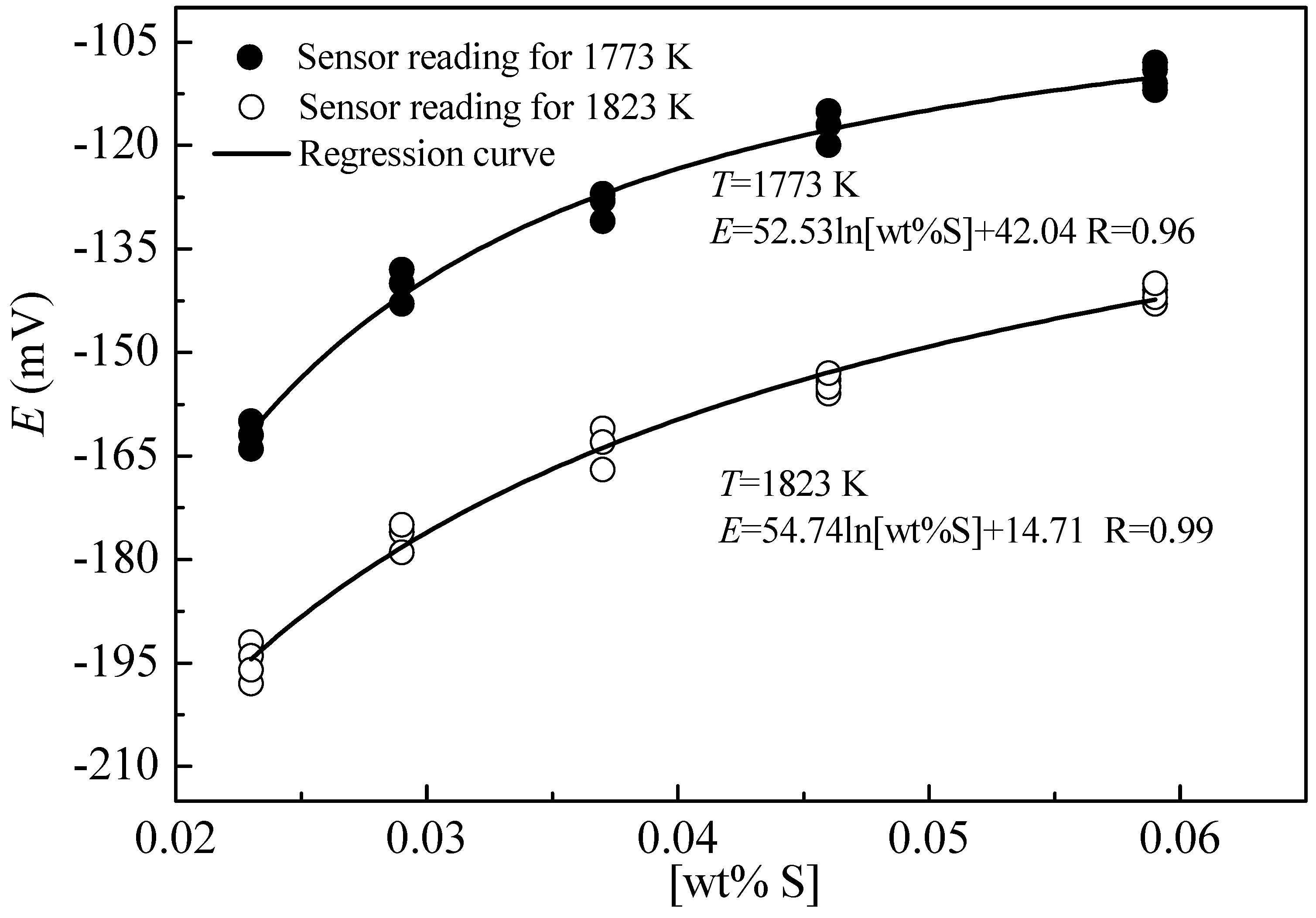
Figure 5 shows a typical result of the sulfur sensor for a laboratory experiment at 1773 K and 1823 K, where the sensor EMF was plotted against sulfur content in the range of 0.02–0.1 wt pct analyzed using chemical analysis method in the iron. As can be seen, the sensor EMF was sensitive to the variation of the sulfur content and the accuracy was satisfactory. Meanwhile, the relationship between EMF and [wt% S] is logarithmic. Therefore, the sulfur content can be calculated through the following empirical equation based on the EMF measured with the sulfur sensors:
The above sulfur sensor overcame the defect that sulfide was easy to oxidize as auxiliary electrode, and obviously simplified the manufacturing process. The processing cost was greatly reduced and the sensor could be kept for a long time without any special protection, which created a necessary condition for industrial applications.
4. Conclusions
In this work, the ZrO2(MgO)/CaAl2O4+CaAl4O7 bilayer structure used for a sulfur sensor was successfully fabricated by the laser powder cladding method using CaAl2O4 and CaAl4O7 as the coating materials and ZrO2(MgO) as the substrate. The properties of this structure in terms of the microstructure, composition, ionic conductivity and application in sulfur determination were investigated. The conclusions drawn are as follows.
- (1)
- The laser cladding layer was composed of Ca0.15Zr0.85O1.85, CaAl2O4 and CaAl4O7 phases, which achieved good densification and adheres to the substrate firmly.
- (2)
- The fine bilayer structure showed a high ionic conductivity that increased linearly with the increase of temperature.
- (3)
- The sulfur sensor was assembled using the fabricated bilayer structure to measure the sulfur content in the carbon-saturated liquid iron, and the sulfur content could be calculated through the following empirical equation based on the EMF measured with the sensor:
Author Contributions
J.Y. and T.W. designed the experiment and wrote the paper; E.J. performed the experiments; Y.Z. and C.T. prepared the calcium aluminate powders used as the coating materials; L.Y. guided the experiments and revised the original paper. All authors contributed to the analyses and discussion of the results.
Funding
This research was funded by the National Natural Science Foundation of China (51874083, 51404056).
Acknowledgments
This work was financially supported by the National Natural Science Foundation of China (51874083, 51404056).
Conflicts of Interest
The authors declare no conflict of interest.
References
- Fischer, W.A.; Janke, D. Metallurgische Elektrochemie; Springer: Berlin, Germany, 1975. [Google Scholar]
- Ono, K.; Oishi, T.; Moriyama, J. Measurements on galvanic cells involving solid-sulphide electrolytes. Solid State Ion. 1981, 3, 555–558. [Google Scholar] [CrossRef]
- Ono, K.; Moriyama, J. Rapid electrochemical determination of dissolved sulphur in liquid copper by solid-sulphide electrolytes. Solid State Ion. 1981, 2, 127–130. [Google Scholar] [CrossRef]
- Egami, A.; Onoye, T.; Narita, K. Solid electrolyte for the determination of sulfur in liquid iron. Solid State Ion. 1981, 3, 617–620. [Google Scholar] [CrossRef]
- Gu, L.J.; Tang, Z.H. Study on the determination of sulfur activities in liquid iron by means of a sulfur concentration cell with a solid electrolyte CaS(TiS2). Kang T’ieh/Iron Steel 1984, 19, 13–19. [Google Scholar]
- Gozzi, D.; Granati, P. Sulfur determination in carbon-saturated iron by solid-state electrochemical sensor. Metall. Mater. Trans. B 1994, 25, 561–568. [Google Scholar] [CrossRef]
- Hong, Y.R.; Jin, C.J.; Li, L.S.; Sun, J.L. An application of the electrochemical sulfur sensor in steelmaking. Sens. Actuator B Chem. 2002, 87, 13–17. [Google Scholar] [CrossRef]
- Zhang, Z.W.; Feng, G.S.; Zhang, J.L.; Cao, C.G. Development of sulfur sensor for quick analysis of hot metal. Iron Steel 2000, 35, 57–61. [Google Scholar]
- Liu, T.; Li, L.; Yu, J.K. An electrochemical sulfur sensor based on ZrO2(MgO) as solid electrolyte and ZrS2+MgS as auxiliary electrode. Sens. Actuator B Chem. 2009, 139, 501–504. [Google Scholar] [CrossRef]
- Liu, T.; Yu, J.K.; Chen, M. Synthesizing sulphides by a temperature gradient method. Ceram. Int. 2007, 33, 321–325. [Google Scholar] [CrossRef]
- Mao, F.X.; Yu, J.K.; Liu, T.; Jiang, Y.F. Synthesis of an auxiliary electrode by laser cladding coating for in-situ electrochemical sulfur sensing. Mater. Lett. 2015, 138, 276–278. [Google Scholar] [CrossRef]
- Michalek, K.; Čamek, L.; Gryc, K.; Tkadleckova, M.; Huczala, T.; Troszok, V. Desulphurization of the high-alloy and middle-alloy steels under the conditions of an EAF by means of synthetic slag based on CaO−Al2O3. Mater. Tehnol. 2012, 46, 297–303. [Google Scholar]
- Yan, P.C.; Huang, S.G.; Dyck, V.J.; Guo, M.X.; Blanpain, B. Desulphurisation and inclusion behaviour of stainless steel refining by using CaO-Al2O3 based slag at low sulphur levels. Trans. Iron Steel Inst. Jpn. 2014, 54, 72–81. [Google Scholar] [CrossRef]
- Yan, P.C.; Guo, X.L.; Huang, S.G.; Dyck, V.J.; Guo, M.X.; Blanpain, B. Desulphurisation of stainless steel by using CaO-Al2O3 based slags during secondary metallurgy. ISIJ Int. 2013, 53, 459–467. [Google Scholar] [CrossRef]
- Wen, T.P.; Yu, J.K.; Jin, E.D.; Liu, T.; Hou, X.H.; Sun, Q.Y. Application of solid electrochemical sulfur sensor in the liquid iron. Sens. Actuator B Chem. 2019, 279, 177–182. [Google Scholar] [CrossRef]
- Wang, C.Z. Solid Electrolyte and Chemical Sensors; Metallurgical Industry Press: Beijing, China, 2000; pp. 73–117. [Google Scholar]
Figure 1.
Schematic drawing of the assembled sulfur sensor.
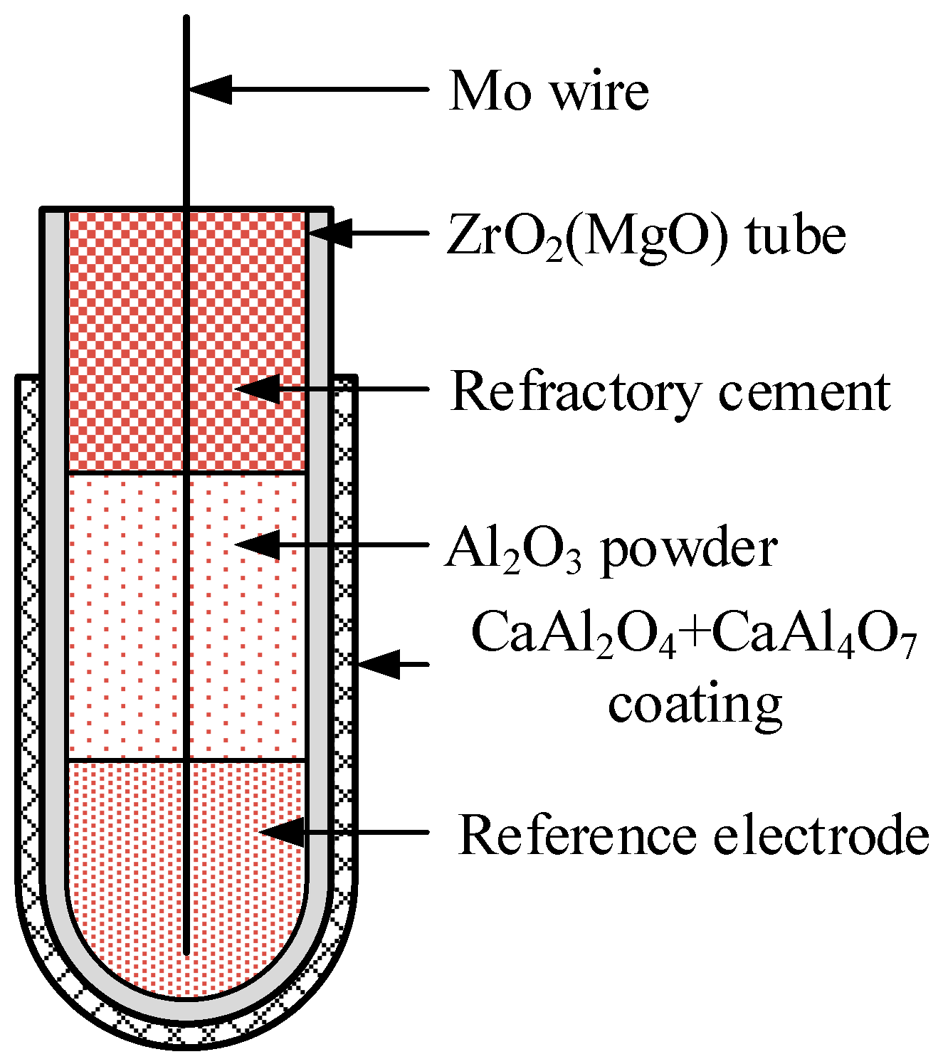
Figure 2.
X-ray diffraction (XRD) patterns of the samples (a) before and (b) after laser cladding.

Figure 3.
(a,b) Scanning electron microscope (SEM) micrographs and (c) line scan of the cross-section of the fabricated sample.
Figure 3.
(a,b) Scanning electron microscope (SEM) micrographs and (c) line scan of the cross-section of the fabricated sample.
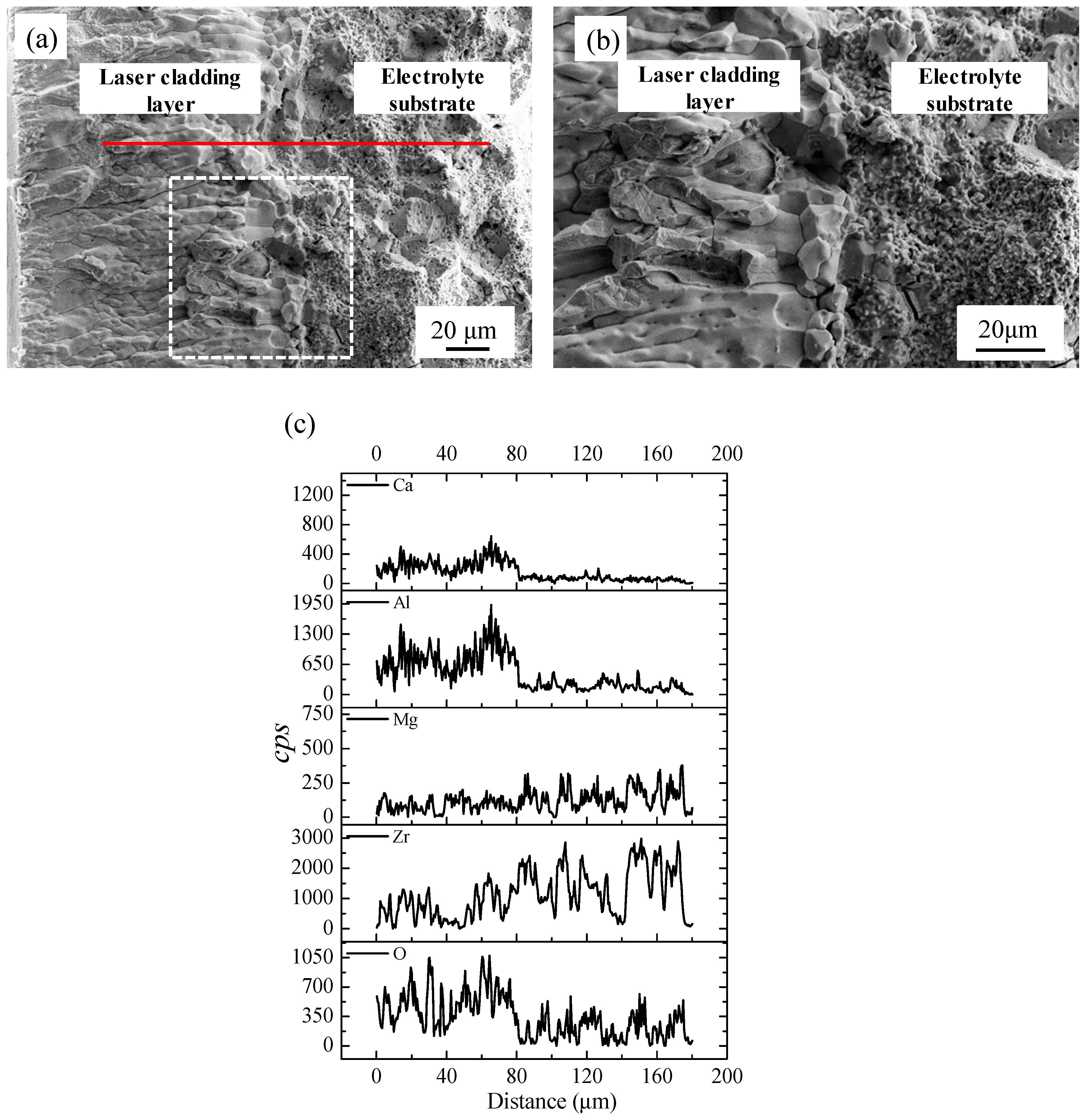
Figure 4.
Arrhenius plots of ionic conductivity of the fabricated sample.
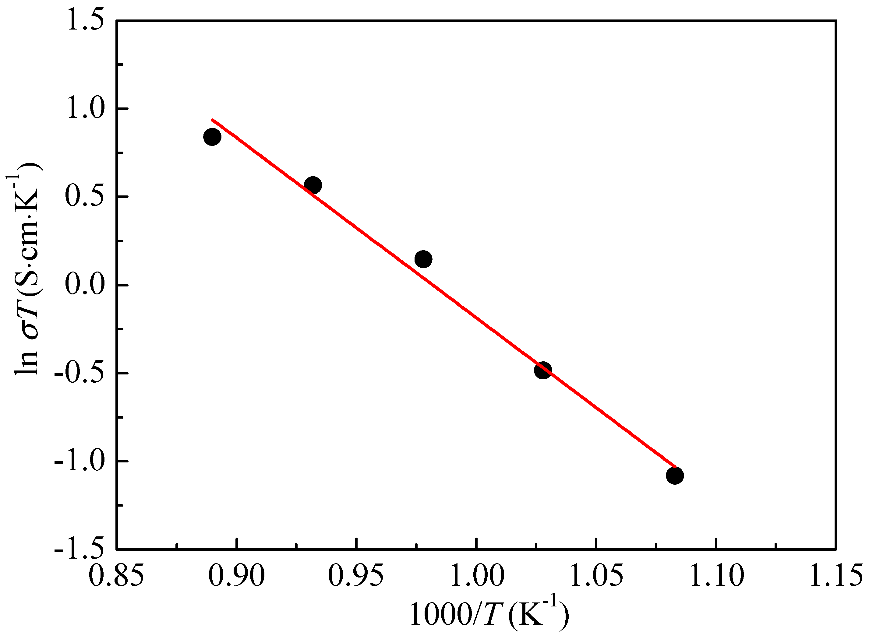
Figure 5.
Relationship between sensor electromotive force (EMF) and sulfur content.

Table 1.
Experimental process parameters of laser powder cladding (LPC).
| Contents | Parameter |
|---|---|
| Average power | 500 W |
| Impulse frequency | 14 Hz |
| Pulse width | 3.0 ms |
| Defocusing amount | 50 mm |
| Scanning speed | 2.5 mm·s−1 |
| Overlapping ratio | 45% |
© 2019 by the authors. Licensee MDPI, Basel, Switzerland. This article is an open access article distributed under the terms and conditions of the Creative Commons Attribution (CC BY) license (http://creativecommons.org/licenses/by/4.0/).
Share and Cite
MDPI and ACS Style
Wen, T.; Yu, J.; Jin, E.; Yuan, L.; Zhou, Y.; Tian, C. Fabrication of ZrO2(MgO)/CaAl2O4+CaAl4O7 Bilayer Structure Used for Sulfur Sensor by Laser Cladding. Appl. Sci. 2019, 9, 1036. https://doi.org/10.3390/app9061036
AMA Style
Wen T, Yu J, Jin E, Yuan L, Zhou Y, Tian C. Fabrication of ZrO2(MgO)/CaAl2O4+CaAl4O7 Bilayer Structure Used for Sulfur Sensor by Laser Cladding. Applied Sciences. 2019; 9(6):1036. https://doi.org/10.3390/app9061036
Chicago/Turabian StyleWen, Tianpeng, Jingkun Yu, Endong Jin, Lei Yuan, Yuting Zhou, and Chen Tian. 2019. "Fabrication of ZrO2(MgO)/CaAl2O4+CaAl4O7 Bilayer Structure Used for Sulfur Sensor by Laser Cladding" Applied Sciences 9, no. 6: 1036. https://doi.org/10.3390/app9061036
Note that from the first issue of 2016, this journal uses article numbers instead of page numbers. See further details here.