1. Introduction
With the continuous advancement of human exploration of the universe, the demand for higher optical resolution has driven the aerospace observatory moving forward to the larger aperture ultraviolet-optical-infrared (UVOIR) space telescopes, with the primary mirror (PM) segmented [
1,
2]. The prospective space assembled telescope [
3,
4,
5,
6] will enable optical elements to be launched in batches, compared with traditional space optical telescopes employing monolithic optics [
7]. Therefore, future space observation systems will overcome the launching mass and volume limitations. However, a critical issue is effectively capturing and connecting the precise optical mirror segments in space to determine the optical stability of the telescope structure [
8].
The connection technology applied between primary mirror assemblies (PMAs) means that two or more modular units are connected rigidly by locking mechanisms, with special docking interfaces to form the core of the synthetic aperture. Then, the co-focal and co-phase adjustment operations are executed with actuators attached to the backside of the individual mirror segments, thereby directly contributing to the optical performance. The space probe-cone docking mechanism is ideally suitable for the space small-scale cooperative target self-assembly tasks, mainly due to the high reliability of capture, high docking precision, and very compact structure. Because of the microgravity environment in space, a strong coupling effect exists between free-floating space objects in the docking process. Therefore, a buffer system is essential to alleviating the influence of the docking impact and controlling the contact force. However, considering the size compactness and power efficiency, it is difficult for complex active buffer systems to join this type of docking mechanism. In other words, if there is a simple solution to mitigate the impact coupling effectively during the assembly period, the probability for assembling PMAs on orbit will be greatly improved.
At present, many organizations [
9,
10,
11,
12] are conducting research on connection technology using space small-scale targets. The autonomous micro-satellite docking system (AMDS) [
13,
14], developed by the Orbital Express (OE) project, utilized soft-docking technology [
15] to buffer the impact. However, the docking conditions of this technology were harsh, undermining the overall capture rate. The Engineering Test Satellite VII (ETS-VII) [
16] demonstrated autonomous rendezvous and docking experiments in space. The universal docking port (UDP), developed by the Synchronized Position Hold Engage Reorient Experimental Satellites (SPHERES) team [
17], adopted the electromagnetic techniques [
18,
19] for active buffering. Its operation was difficult and energy consumption could not be ignored.
In this paper, a novel design methodology named “double-elastic contact model,” is mainly developed for the passive buffer system between the modular PMAs to assemble one large-scale apertures. A connection mechanism called the Self-configurable Modular Adjustable Latch Lock (SMALL) is provided, using the passive buffer system to mitigate the impact. Through the universal explicit probe-cone interface, this simple and compact design contributes immensely to segmented mirrors to function monolithically. This paper is organized as follows.
Section 2 analyzes the general capture process of the autonomous probe-cone docking mechanism for modular assembled mirror segments. And the “double-elastic contact model” is investigated in detail. In
Section 3, a passive buffer system applied to the connection mechanism SMALL is implemented and analyzed to verify the theory mentioned in
Section 2.
Section 5 concludes our statements.
2. Establishment of Double-Elastic Contact Model
According to the mission requirements of the space assembled telescope, and the collision characteristics of the probe-cone connection mechanism, the docking process between PMAs should be divided as follows.
First collision. Within a reasonable capture range, two PMAs could achieve a capture operation of weak impact, preventing strong vibrations and interference of the mirrors.
Positioning. It is necessary to limit partial degrees of freedom (DOFs) between two PMAs to align and steady the combination.
Locking and Adjustment. A mechanically rigid connection between the optical elements is required. At the same time, the ability of mirror gap adjustment is a pre-requisite in improving optical performance.
Separation. The feasible undocking maneuver of the connection mechanism should be satisfied in case of unpredictable incidents, such as abnormal docking or irreversible collision.
The buffer performance design mainly focuses on the first point mentioned above, because it produces the largest impact influence, which means the buffer mechanism should be required to absorb the impact energy.
In our previous studies of the typical small-sized cooperative target collision system [
20], the rigid protruding pin B made the first contact with the rigid chamfered entrance hole A, during the capture stage as shown in
Figure 1. The conditions for successful capture by analysis are:
where
β represents the half cone angle of the chamfered hole
A; the entrance angle, and the exit angle of the pin B, are represented by
, respectively. The normal and tangential velocities of the contact point before impact are shown as
,
, respectively. Similarly,
,
represent the normal and tangential velocities of the contact point after impact. In addition, the velocity ratio before, and after, the collision is defined as the recovery factor
S;
T stands for the equivalent stiffness;
M is expressed by the equivalent mass of the connection mechanism; the coefficient of friction angle of conical surface is shown as
μ; the angle between the vector of the two docking mechanisms centroid to collision point and the normal of the cone is expressed by
θ;
is the moment of inertia around the
Z axis of the mechanism.
According to Equation (1), in the case of successful capture, the relationship between the velocity of the rigid pin and the rigid inner-wall of the hole can be obtained by:
However, in the actual space on-orbit assembly environment, a rigid collision can cause irreversible damage to the mirror, such as vibration and interference damage. Therefore, a buffer system needs to be added to mitigate the effects of impact during the docking process. To minimize the energy requirements on such a large cluster of PMAs processing, a passive buffer system, rather than an electromagnet driving one, was developed in this paper. For this purpose, “double-elastic contact model” is established to satisfy this buffer system.
To satisfy the optical specifications and ensure the impact force absorption, storage, and consumption, a passive buffer system was designed and analyzed. On the basis of the structural shape, the pin and the inner-wall of the entrance hole are re-designed flexibly in the probe-cone docking system. In this study, the “double-elastic contact model” was established to study the collision, between the elastic head of the protruding pin and the elastic inner-wall of the entrance hole, during the capture stage. This model is helpful in analyzing whether the maximum deformation and maximum compressive stress meet the assembly requirements of the on-orbit telescope.
Under the double-elastic contact model,
Figure 2 illustrates the details of transient docking collision where the elastic head of the protruding pin
B collides with the elastic inner-wall of conical hole
A with non-zero incident angle
ε0 and velocity
v0 in the position
i. The maximum deformation
δ is produced on the contact surface of
A when the pin head of
B moves to the position
ii. The pin head leaves the elastic wall at the position
iii through the exit angle
ε1 and exit velocity
vk. At position
ii, centered on the collision point
O, the sectional view can be obtained in the plane perpendicular to the common normal of the collision point, as shown in the red region of
Figure 2. Since the deformation
δ, caused by the contact, is much smaller than the radius of the elastic inner-wall
Ra and the pin head
Rb, it is assumed that the radius
R1 is expressed by
R1 =
Ra/cos
β and the spherical cone head radius is
R2 =
Rb. Therefore, the contact pressure and contact deformation will be discussed.
As
Figure 3 shows, during capture stage, it is assumed that the elastic pin head collides with the elastic inner-wall, at point
O under the driving force
F. A local coordinate system
OXY is established with the contact point
O as the origin. The
X-axis, and
Y-axis, represent the common normal, and tangential direction of the collision location, respectively. It is assumed that two points
C (
x1,
ξ) and
D (
x2,
ξ) are taken arbitrarily and will coincide to anyone point within the contact surface during the collision. Then according to the geometric relationship, it can be obtained that
Therefore, the deformation
δ of the collision can be represented as:
where
e1 and
e2 represent the displacement of deformation generated by the point
C and the point
D during the collision, respectively.
From the Equations (3) and (4), the deformation
δ can be written by
where
E1,
E2, and
v1,
v2 represent the Young’s modulus and Poisson’s ratio of the elastic inner-wall of
A, and the elastic head of
B, respectively.
f is shown as a compressive stress function, whose integral area is the entire contact surface.
According to the Hertz theory of elastic mechanics, the compressive stress function,
f can be solved by the semi-inverse solution method. Assuming that the compressive stress function
f on the contact circle of radius
u is proportional to the ordinate of the hemispherical surface, so we can get:
By comparing the coefficients on both sides of the Equation (6), it can be easily seen that Equation (6) can be rearranged as:
where
f0 is represented as the maximum compressive stress on the contact circle.
According to the equilibrium condition, the product of the volume of the hemisphere mentioned above and
should be equal to the driving force, which can be shown as:
From Equations (7) and (8), the radius
u of contact circle and the maximum deformation
δ can be obtained by:
The maximum compressive stress
f0 occurs at the center of the contact surface, and its value is:
Since k is related to the Young’s modulus E, and the Poisson’s ratio v of the elastic pin head and the elastic wall surface, the value of the maximum compressive stress f0 can be determined as long as we know the wall radius, R1 at the collision point O, and the magnitude of the driving force.
3. Buffer System Validation
At present, one of the important factors restricting the development of on-orbit PM assembly is how to connect the modular PMAs, which can ensure that the assembled telescope achieve optical performance requirements. The mechanical strength and precision need to be satisfied between PMAs, so the design of the connection mechanism plays an important role. In this section, the proposed double-elastic contact model is considered for the androgynous connection mechanism, SMALL. This modulization scheme is a critical conceptual upgrade attached to the optical elements, as illustrated in
Figure 4.
It is predominantly comprised of: A chamfered entrance hole and a grooved protruding pin which increase docking tolerances; a positioning channel to correct alignment error by limiting five degrees of freedom (DOFs); a latch lock to connect two adjacent modules rigidly; and a linear actuator to control the clearance between combined parts. This compact and simple interface is attached to the outer wall of the PMA base, which solves the defects, such as high energy consumption, high operation difficulty, insufficient locking force, and low adjustment precision, compared with the traditional connection mechanism.
The operation principle of SMALL is explained as shown in
Figure 5. In the capture stage, under the monitoring of the camera, two SMALLs are simultaneously close to each other. The pins will make contact with the opposing holes, as shown in
Figure 5a. During the positioning stage, the pins enter the positioning channels to limit five DOFs of the combination. Only one DOF is left along the axis hole direction, as shown in
Figure 5b. In the locking and adjustment stage, the groove of the pin engages with the locking mechanism, which has twelve locking teeth [
21]. After the lock is completed, the internal actuators of SMALLs start to align the gap between the two mirror segments to a reasonable range, as shown in
Figure 5c. In the separation stage, the locking teeth expand outwards, with the assistance of the extended semi-rigid stick within the grooved pin, separating the two connection mechanisms from each other as shown in
Figure 5d.
The SMALL adopts a flexible design of the inner-wall of the tapered cone. Eight flexure sections are evenly distributed on the chamfered surface. As shown in
Figure 4, the gap between the flexible sections and the tapered surface is consistent. According to the design requirements, the deformation of the buffer system should be within 0.002 m according to the material properties and structural characteristics.
Taking the actual working environment into account, it is assumed that the driving force is with the range of 100 N~500 N, and the protruding pin and the inner-wall of the hole are made of TC4. The docking parameter specifications are shown in
Table 1.
According to the double-elastic model, the deformation and compressive stress can be acquired from
Depending on the location of the collision point, the value of the
R1 is changing. Assuming that the
Z-axis is along with the center axis of the conical hole, and the propulsion depth of the pin head is denoted by
z, the elastic pin head makes the first collision with the elastic inner wall. Then there is:
With the different values of F, the maximum deformation and the maximum compressive stress are shown below.
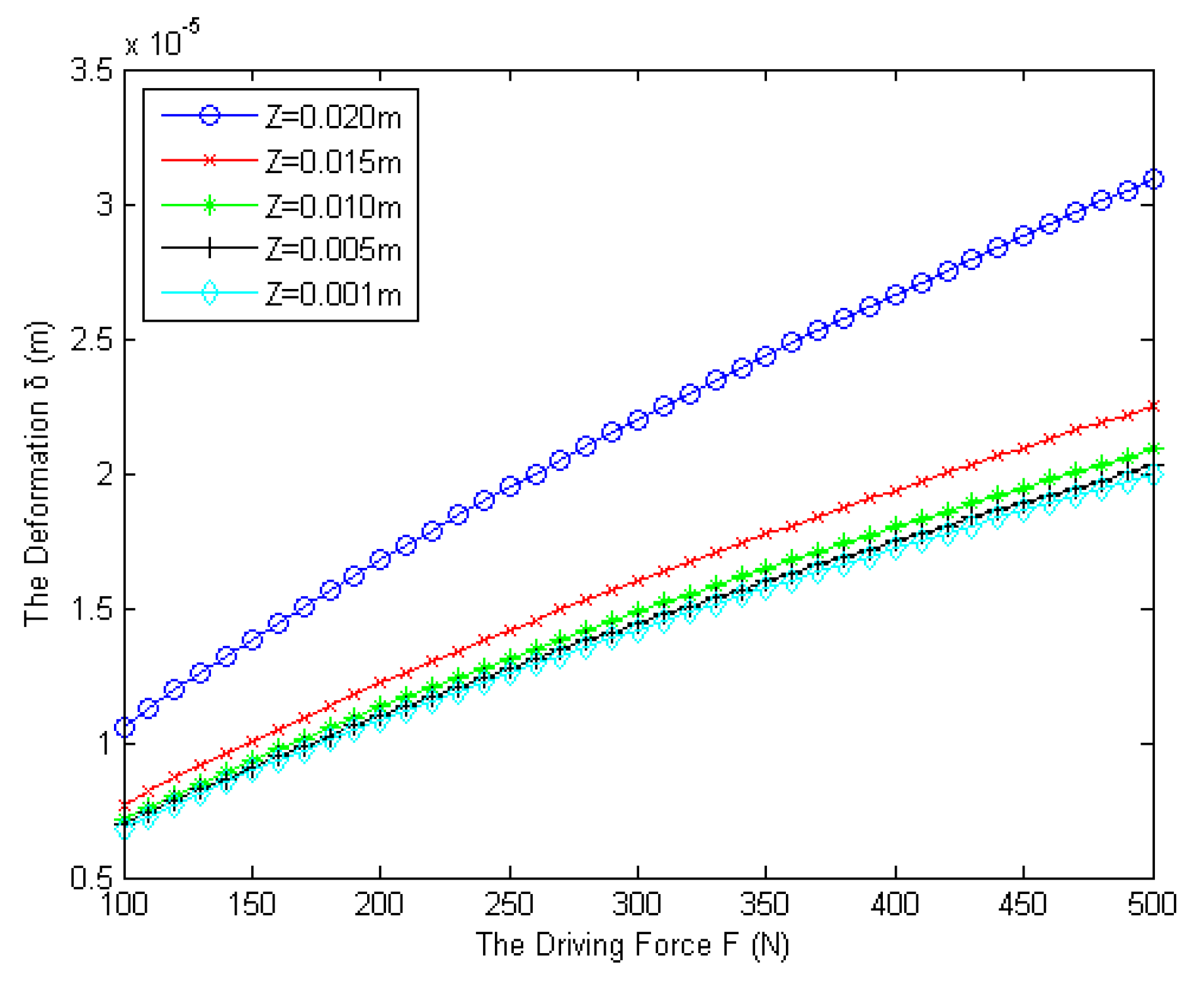
The line graph, illustrated in
Figure 6, demonstrates the relationship between the maximum collision deformation and the driving force under different depths of propulsion. It is obvious that the deformation value rises considerably as the driving force increases from 100 N to 500 N, revealing that the buffer system has a good absorption of impact energy. As shown in the curve, the deformation at Z = 0.020 m is far beyond the others, generally appearing in the span from 1 × 10
5 m to 3 × 10
5 m, which shows the effect of deformation on the bottom of the chamfered hole is evident. However, it is necessary to point out that the deformation value still does not exceed the specified requirements.
The relationship between the maximum compressive stress and the driving force is delivered by
Figure 7. The rising trends of the compressive stress, under different depths of propulsion, always keep at a slow rate, showing this system is very effective in damping the impact force. Although the compressive stress remains in a secure range, it is worth mentioning that the line at Z = 0.020 m is still much higher than the others, going up from 1.5 × 10
9 Pa to 2.5 × 10
9 Pa. Therefore, efforts should be made to avoid the contact position too close to the bottom of the chamfered hole, in case of damage to the PMAs.
4. Simulation Analysis
In order to test and verify the buffer ability of the proposed theory, there should be evaluation to assess whether the capture contact meets the requirements of optical assembly. Due to a lack of experiment environment and equipment, it is an effective method for the dynamic simulation on computer to validate the parameters of the buffer system designed.
A stack of parameters with zero gravity environment were chosen to compare the magnitude of the collision, such as axial docking velocity, lateral deviation, and roll angular velocity. One PMA is designed to remain stationary and stable at the center of the simulated environment. Meanwhile, another PMA approaches and connects with it via the parameterized docking maneuver. Referring to docking data from Automated Rendezvous and Docking of Spacecraft [
22] and SPHERES docking experiment [
23], typical initial docking conditions of SMALL are listed in
Table 2.
The thrust value is set to 100 N. Taking the androgyny characteristic of SMALL into account, there will be two contact positions for the probe-cone docking process. Due to the existence of the docking deviation, there is always a case where a set of pin and hole is contacted, and then another set is contacted. Under the above conditions, the docking simulation between the two PMAs is performed by Adams software. The contact force diagram of a typical rigid collision system is shown as
Figure 8. Likewise, that of the double-elastic collision system is shown as
Figure 9.
Under the same docking conditions, the contact forces between the first set are almost the same, as the red lines shows in
Figure 8 and
Figure 9. However, by comparison, it should be noted that the contact force of the second set of pins and holes produced a significant change. The connection mechanism, using the passive buffer system, generates a collision force much smaller than that of the conventional un-buffered system. The contact force decay rate under the double-elastic contact model is 58%, which is much larger than 10% under the traditional rigid collision. Therefore, it can be concluded that the double-elastic contact model is feasible.


