A Quantitative Index to Evaluate the Commutation Failure Probability of LCC-HVDC with a Synchronous Condenser


State Key Laboratory of Alternate Electrical Power System with Renewable Energy Sources, North China Electric Power University, Beijing 102206, China
*
Author to whom correspondence should be addressed.
Appl. Sci. 2019, 9(5), 925; https://doi.org/10.3390/app9050925
Submission received: 9 January 2019
/
Revised: 26 February 2019
/
Accepted: 27 February 2019
/
Published: 5 March 2019
(This article belongs to the Special Issue HVDC for Grid Services in Electric Power Systems)
Abstract
:Featured Application
The new index of area ratio of the commutation failure probability is expected to evaluate the commutation failure under a wider fault range from the transient performance, which is helpful to evaluate the impact of dynamic reactive power compensators on the commutation failure probability of LCC-HVDC.
Abstract
Since thyristor cannot turn off automatically, line commutated converter based high voltage direct current (LCC-HVDC) will inevitably fail to commutate and therefore auxiliary controls or voltage control devices are needed to improve the commutation failure immunity of the LCC-HVDC system. The voltage control device, a synchronous condenser (SC), can effectively suppress the commutation failure of the LCC-HVDC system. However, there is a need for a proper evaluation index that can quantitatively assess the ability of the LCC-HVDC system to resist the occurrence of commutation failures. At present, the main quantitative evaluation indicators include the commutation failure immunity index and the commutation failure probability index. Although they can reflect the resistance of the LCC-HVDC system to commutation failures to a certain extent, they are all based on specific working conditions and cannot comprehensively evaluate the impact of SCs on suppressing the commutation failure of the LCC-HVDC system under certain fault ranges. In order to more comprehensively and quantitatively evaluate the influence of SCs on the commutation failure susceptibility of the LCC-HVDC system under certain fault ranges, this paper proposes the area ratio of commutation failure probability. The accuracy of this new index was verified through the PSCAD/EMTDC. Based on the CIGRE benchmark model, the effects of different synchronous condensers on LCC-HVDC commutation failure were analyzed. The results showed that the new index could effectively and more precisely evaluate the effect of SCs on commutation failures. Moreover, the proposed index could provide a theoretical basis for the capacity allocation of SCs in practical projects and it could also be utilized for evaluating the impact of other dynamic reactive power compensators on the commutation failure probability of the LCC-HVDC system under certain fault ranges.
1. Introduction
The LCC-HVDC system is widely used in the world due to its numerous advantages such as bulk direct current (DC) power transmission over long distances and asynchronous interconnection of alternating current (AC) grids [1]. However, due to the use of thyristor technology, the LCC-HVDC system can exhibit the commutation failure during various system disturbances [2]. One of the main reasons for commutation failure is the AC busbar voltage drop that occurs during fault conditions [3,4]. Therefore, it is necessary to quickly and effectively regulate the AC busbar voltage during faulty conditions so that the probability of commutation failure can be reduced. Dynamic reactive power compensators can be installed at the inverter side to achieve quick voltage regulation of the AC busbar by supplying a surplus of reactive power and thus decreasing the probability of commutation failure [5]. The synchronous condenser (SC), a type of dynamic reactive power compensator, can increase the AC system’s strength due to the shunting effect of the transient reactance during steady and transient states [6]. It is therefore widely used in real-world LCC-HVDC systems to effectively regulate the AC voltage and thus avoid commutation failure. Recently, SCs have been installed in several LCC-HVDC projects in China to enhance the system’s strength and mitigate commutation failures. Hence it is necessary to present an index that can quantitatively and comprehensively assess the influence of SCs on the commutation failure of the LCC-HVDC systems.
Several works have focused on evaluating the commutation failure of the LCC-HVDC system. An area of vulnerability (AOV) was discussed and a mechanism for the optimal allocation of dynamic VAR sources was proposed in [7] in order to decrease the commutation failure probability of the LCC-HVDC system at the inverter end. However, due to the use of steady-state equations for calculating the probability of commutation failure, the transient behavior of the extinction angle and phase shift in the AC voltage were not considered, which could lead to a decrease in the accuracy of the results. An analytical approach to investigate the immunity levels to commutation failure of the multi-infeed LCC-HVDC system was presented [8]. However, the dynamic responses during transient conditions and the effects of different reactive power compensators were not considered. A fast calculation approach to evaluate the risk of commutation failure in the multi-infeed LCC-HVDC system was proposed [9]. However, the transient responses of different control parameters were not undertaken. The commutation failure in the LCC-HVDC system using the spatial-temporal discreteness of AC disturbances was investigated [10]. However, this approach was based on a steady-state model, which meant that results obtained under different fault situations could have a lack in accuracy. Two indices, referred to as the commutation failure immunity index (CFII) and commutation failure probability index (CFPI), were proposed in [11]. This approach was based on transient simulations, however could only evaluate the commutation failure under certain faulty conditions. Thus, it is meaningful to propose a more comprehensive index to evaluate the commutation failure under a wider fault range from the transient performance.
This paper proposes a novel index termed as area ratio of commutation failure probability, to comprehensively and quantitatively evaluate the commutation failure of the LCC-HVDC system with a SC under certain fault ranges. Considering the CIGRE benchmark model, the LCC-HVDC system with a SC was built in the PSCAD/EMTDC. Different scenarios assuming the number of synchronous condenser units were carried out in order to examine its effect on the area ratio of the commutation failure probability of the LCC-HVDC system. The effectiveness of the proposed index was validated through simulation results under different fault types and fault severity conditions.
The paper is arranged as follows. In Section 2, a detailed configuration of the LCC-HVDC system with a SC is presented. In Section 3, the overall control mechanism for the LCC-HVDC systems and a SC is discussed. In Section 4, a new index termed as area ratio of commutation failure probability is proposed and verified through the PSCAD/EMTDC under different fault conditions. In Section 5, the conclusion is provided.
2. Configuration of LCC-HVDC with a Synchronous Condenser
The configuration of the mono-polar LCC-HVDC system with SCs is shown in Figure 1. The HVDC station is composed of two six-pulse converters connected in series. The SC is connected to the AC bus at the inverter side via a step-up converter transformer. The rated DC power of the LCC-HVDC system is 1000 MW and the rated reactive power of the SC is 100 Mvar.
The main parameters of the LCC-HVDC system with a SC are summarized in Table 1.
3. Control Mechanism for LCC-HVDC with a Synchronous Condenser
3.1. Control Mechanism for LCC-HVDC
The control system of the LCC-HVDC is consistent with the CIGRE benchmark model [12]. The system operates in the constant current control mode with a minimum firing angle at the rectifier end, and adopts a constant extinction angle control mode at the inverter end, which is also equipped with a constant current control mode and a current error controller (CEC) mechanism. The constant current control at the inverter side is used as a backup control mechanism during severe AC and DC disturbances. It contains a voltage-dependent current order limiter (VDCOL) function, which helps in limiting the DC overcurrent and avoiding the stress on thyristor valves during different fault conditions. Figure 2 presents the overall control mechanism for the LCC-HVDC system.
3.2. Control Mechanism for the Synchronous Condenser
The basic control mechanism for the SC is shown in Figure 3. The measured AC voltage and excitation current, shown as Ut and If, respectively, are the input variables, and the excitation voltage Ef is generated via proportional-integral (PI) function and then delivered to the exciter system. The SC adopts the constant voltage control mode to adjust the AC bus voltage during both steady-state and transient situations. When an AC fault is applied at the AC busbar, the increase in the excitation current causes the excitation voltage of the SC to increase in order to provide a certain amount of reactive power needed for AC voltage regulation. If the fault is serious or lasts for a longer time, the excitation current could reach the maximum over-excitation current value. This will activate the maximum excitation current limitation function by the control-signal of the If_mark to limit the excitation current around the referenced value of Ifmax_ref. However, it is not allowed to keep the maximum over-excitation current as Ifmax_ref for a long time. When the operating time of SC with Ifmax_ref exceeds the allowable time, the anti-time over-excitation limiter will activate the over-excitation current limitation function by the control-signal of OEL_mark, so as to limit the over-excitation current to a level of If_ref under which the SC can keep operating for a longer time, finally to avoid the internal overheating of the SC.
4. Using the Area Ratio of Commutation Failure Probability to Evaluate the Effect of SCs on the Commutation Failure Immunity of LCC-HVDC
In order to further study the suppression effect of SCs on the commutation failure of the LCC-HVDC system, firstly, the simulation from PSCAD/EMTDC with different numbers of SCs was compared to verify the effectiveness of the SCs on suppressing the commutation failure. Then, a new index called area ratio of commutation failure probability was proposed. Finally, the area ratio of commutation failure probability index was used to evaluate the suppression effect of the SCs on the commutation failure of the LCC-HVDC system under different short circuit ratios (SCRs) at the inverter side. The following three cases were considered:
Case 1: No synchronous condenser is connected at the AC bus of the inverter side;
Case 2: One synchronous condenser with rated capacity of 100 Mvar is connected at the AC bus of the inverter side;
Case 3: Two synchronous condensers each with rated capacity of 100 Mvar are connected at the AC bus of the inverter side;
4.1. Validation of the Effectiveness of the SCs in Suppressing the Commutation Failure of the LCC-HVDC System
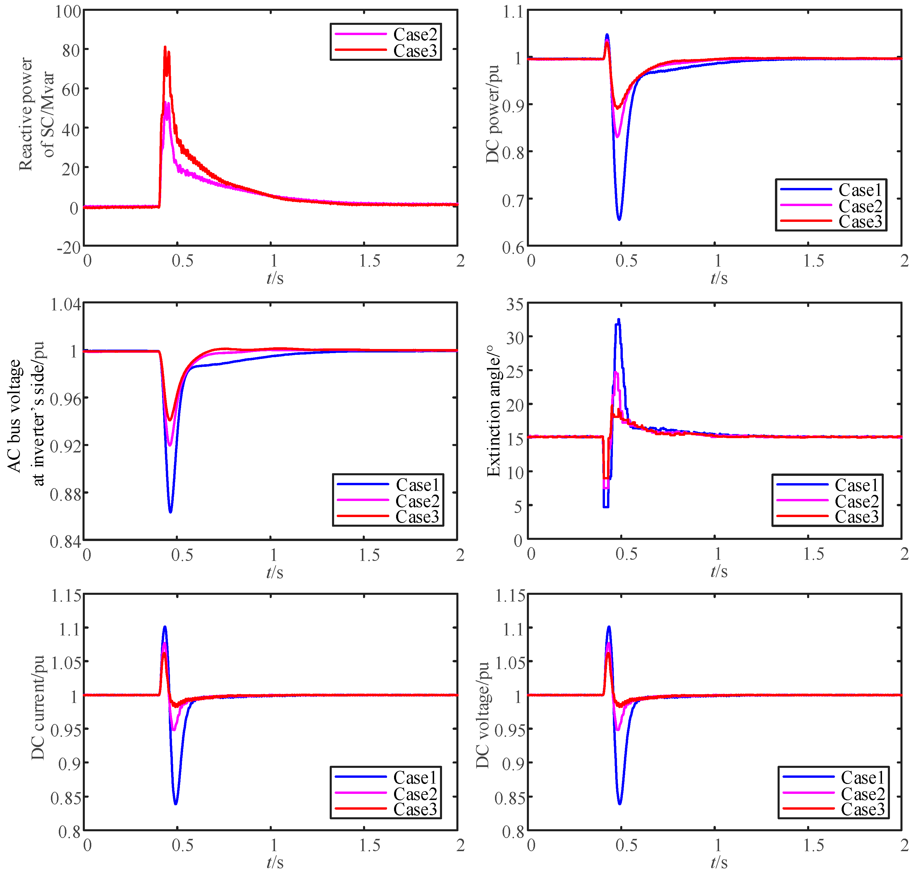
Three-phase fault is the most serious fault among all types of AC faults. Therefore, the same three-phase fault was applied at the inverter bus of three cases to verify the effectiveness of the SC on suppressing commutation failure. The fault inductance value was set to 1.28H (the smallest inductance value that does not result in commutation failure in case 1), the fault time was 5.1s, and the fault duration was 0.05s. The comparison of dynamic responses under the three-phase fault is shown in Figure 4.
The comparison of the dynamic responses of different cases in Figure 4, showed that the DC voltage, DC current, DC power, AC bus voltage, γ and the reactive power of SCs all dropped or rose in varying degrees when the fault occured. Among them, the change range of Case 1 was the largest, on the contrary, it was the smallest in Case 3. Compared with Case 1, the AC bus voltage at the inverter side was supported and the rise of the DC current was restrained in Case 2 and Case 3 because of the reactive power compensation of the SCs, which reduced the drop of γ and effectively restrained the occurrence of commutation failures. The reactive power sent by the SCs in Case 3 was larger than that of Case 2 at the moment of fault. Therefore, Case 3 had a better suppression effect on commutation failure.
4.2. Proposed Area Ratio of Commutation Failure Probability
Previous studies have shown that different numbers of SCs can improve the ability of the LCC-HVDC system to resist commutation failure, but the method for quantitatively evaluating the suppression effect of SCs needs further study.
A single- or three-phase fault occurring at the AC bus of the inverter side may cause a commutation failure to occur in the LCC-HVDC system. The occurrence of a commutation failure is not only sensitive to the severity of the AC fault, but also to the time-instant of when the fault occurs during one AC cycle. Thus, the commutation failure probability index (CFPI) in [11] is used to assess the chances of commutation failure occurrence in the LCC-HVDC system during one cyclic frequency.
To obtain the commutation failure probability curve, different fault levels under specific fault times were considered. A single- or three-phase fault with inductance was applied at the AC busbar and the fault level was varied by changing the inductance value. A simultaneous fault level in the range of 100 fault points was applied while changing the fault time within one AC cycle duration (0.02 s). The multiple run mechanism in the PSCAD/EMTDC examined the occurrence of commutation failure and enlisted all related data. The probability of commutation failure for a specific fault was then evaluated by taking the ratio of faults that could cause commutation failure to the total equivalent fault points in one AC cycle. Multiple simulations were carried out to evaluate the probability for each fault level and to obtain the commutation failure probability curve.
However, when the CFPI was used to quantitatively evaluate the effect of the SC on the commutation failure of the LCC-HVDC system, the evaluation results were only based on a specific fault. It could not fully and intuitively reflect the effect of the SC on the commutation failure of the LCC-HVDC system in a wider fault range and thus could not provide a more comprehensive evaluation for the commutation failure mitigation effect. By comparing the curves of the commutation failure probability before and after the implementation of the SC at the inverter side, it was found that the area surrounded by the curve of the commutation failure probability with the SC was smaller than that without the SC within the same fault range. Considering this, an area ratio of commutation failure probability that could cope with the shortcomings of CFPI was proposed. The flow-chart for calculating the area ratio of commutation failure probability is shown in Figure 5.
The detailed steps for calculating the area ratio of commutation failure probability are as follows:
(1) At the inverter end, the fault with a setting inductance value was applied to the AC busbar and the initial fault time was set with the fault clearance duration.
(2) When no SC was considered, the commutation failure probability of the LCC-HVDC system under a different fault inductance L was obtained. The fault inductance value was defined as Lno_sc, under which the commutation failure probability of the LCC-HVDC system was exactly 0 %.
(3) Considering that SC was linked at the inverter end, the commutation failure probability of the LCC-HVDC system under a different fault inductance L was obtained. The fault inductance value was obtained as Lsc, under which the commutation failure probability of the LCC-HVDC reached 100%. (When there were multiple SCs, the Lsc that could take in the maximum number of SCs was chosen).
(4) With the fault inductance L as abscissa and the commutation failure probability as ordinate, the curve of commutation failure probability with and without SCs was formed as graphically presented in Figure 6. The area between the commutation failure probability curve and horizontal axis [Lsc, Lno_sc] was calculated. Finally, the area ratio of commutation failure probability was computed by taking the ratio of area of commutation failure probability without SC (Sno_sc) to the area of commutation failure probability with SC (Ssc), as analytically expressed in (1).
It was clear from Figure 6 that for the same fault level, the commutation failure probability of LCC-HVDC with the SC was less than that of LCC-HVDC without the SC. Therefore, the calculated area-ratio of commutation failure probability should be less than 1. A smaller value of area ratio of commutation failure probability indicated a better effect of the SC in terms of suppressing the commutation failure of the LCC-HVDC system.
4.3. Application and Validation of the Area Ratio of Commutation Failure Probability
In order to evaluate the suppression effect of the SC on the commutation failure of the LCC-HVDC system within a fault range, and to verify the proposed area ratio of commutation failure probability index under single-phase and three-phase inductive faults, the simulations were conducted when considering different numbers of SCs and different short circuit ratios (SCRs) at the inverter side, based on the electromagnetic transient model of the LCC-HVDC system with SCs.
The area of commutation failure probability in the three cases mentioned above were calculated using complex trapezoidal formula as in (2) and (3):
where,
- h: step change of fault inductance in the simulation;
- Lk: fault inductance in [Lsc, Lno_sc] interval;
- f(Lk): the commutation failure probability corresponding to the fault inductance Lk.
- S: the area of commutation failure probability;
- n: the total number of fault inductance level in [Lsc, Lno_sc];
The LCC-HVDC system was assumed to be operating at a rated nominal value (DC power = 1 p.u., DC voltage =1 p.u.). The short circuit ratios (SCRs) of the AC system at the rectifier and the inverter side of the LCC-HVDC system were both set at 2.5. The curve for the commutation failure probability of the LCC-HVDC system considering the three cases mentioned above during the single-phase inductive fault with changing inductance level is depicted in Figure 7. It is obvious from Figure 7 that in Case 3 with two SCs at the inverter side, the commutation failure probability was 100% for the single-phase fault with an inductance level of 0.25 H. Whereas in Case 2, the commutation failure probability was 100% for the fault inductance level of 0.35 H. Considering Case 1 without the SC, the commutation failure probability was 0% for the single-phase inductive fault with a 0.97 H inductance value. Using these values, the area ratio of commutation failure probability for the three cases under single-phase inductive fault was calculated using Equations (1)–(3).
In order to indicate the severity of a single phase to ground fault, the minimum AC voltage RMS values at LCC inverter side (without a SC) during the fault period, at different fault inductances, are summarized in Table 2.
Figure 8 shows the curve built for the commutation failure probability of the LCC-HVDC system under the three phase-ground inductive faults with an inductance range between 0.7 H and 1.4 H while assuming the three cases. It could be depicted that with two SCs, the commutation failure probability was 100 % under a fault inductance level of 0.78 H. The commutation failure probability with one SC (Case 2) was 100% for a fault inductance value of 0.91 H, whereas the commutation failure probability without the SC was 0% for a fault inductance level of 1.28 H. Considering these values in the three different cases, the area ratio of the commutation failure probability of the LCC-HVDC system under three-phase fault was calculated by applying Equations (1)–(3).
In order to indicate the severity of the three phases to ground fault, the minimum AC voltage RMS values at the LCC inverter side (without a SC) during the fault period, at different fault inductances, are summarized in Table 3.
Table 4 summarizes the area of commutation failure probability and area ratio of commutation failure probability of the LCC-HVDC system with and without the SC under single-phase and three-phase inductive faults.
Table 2 shows that when a single-phase fault was applied to the AC bus at the inverter side, the area of commutation failure probability and the area ratio of commutation failure probability both decreased continuously with the increasing number of SCs. The area ratio of commutation failure probability was 0.6939 and 0.5240 with one SC (Case 2) and two SCs (Case 3), respectively, which indicated an improvement in Case 3 as the area ratio of commutation failure probability was reduced by 0.1699 compared to Case 2. Considering the three-phase fault, the area ratio of commutation failure probability of the LCC-HVDC system with one SC at the inverter side was 0.4687. With two SCs linked to the LCC-HVDC system (Case 3), the area ratio of commutation failure probability was 0.1081, which by comparing with Case 2 revealed that an increasing number of SCs could effectively suppress the commutation failure under the three-phase fault. Thus it could be clearly stated that the proposed area ratio of commutation failure probability could comprehensively evaluate the effect of the SCs on the commutation failure of the LCC-HVDC system under various fault types. In addition, the proposed index took into account various conditions of fault severities within a wider fault range, and was not limited to a specific fault. Comparing with existing indices such as the CFPI, the proposed index could quantitatively evaluate the impact of the SCs in suppressing the commutation failure of the LCC-HVDC system in a comprehensive and easy way.
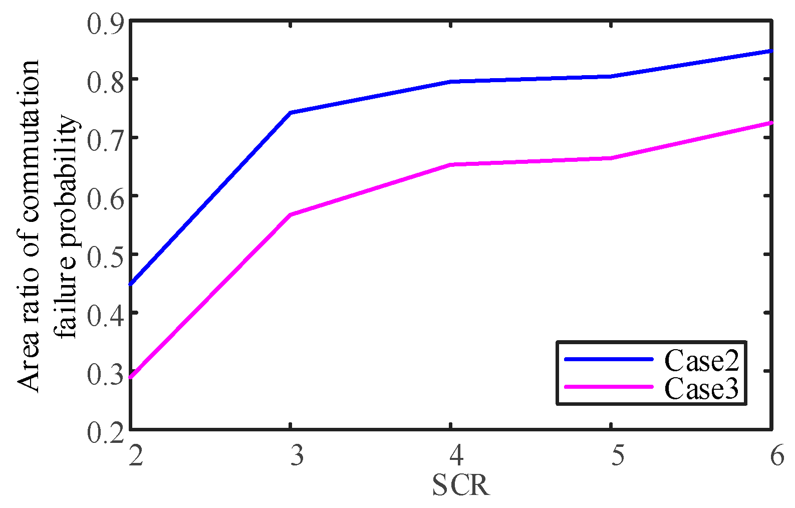
Under different system intensities indicated by the short circuit ratio (SCR), the effect of the SCs on the ability of the LCC-HVDC system to resist commutation failure in a certain fault range varied. Therefore, the single-phase to ground and the three-phase faults were applied respectively at the inverter bus, then the area ratio of commutation failure probability was used to measure the suppression effect of the SCs on commutation failure under different SCRs to obtain the results shown in Figure 9 and Figure 10, respectively.
It could be seen from Figure 9 that when a single-phase fault occurs at the AC bus of the inverter side, the area ratio of commutation failure probability in Case 2 and Case 3 were 0.4487 and 0.2893 respectively when SCR equalled 2; the area ratio of commutation failure probability in Case 2 and Case 3 were 0.8481 and 0.7246, respectively, when SCR equalled 6. It could be seen from Figure 10 that when the three-phase fault occured at the AC bus of the inverter side, the area ratio of commutation failure probability in Case 2 and Case 3 were 0.2305 and 0.0465 respectively when SCR equalled 2, the area ratio of commutation failure probability in Case 2 and Case 3 were 0.5786 and 0.2207, respectively, when SCR equalled 6. Regardless of whether it was under the single phase to ground or three-phase fault, the area ratio of the commutation failure probability of Case 3 was smaller than that of Case 2 under the same SCR, which indicated that an increasing number of SCs could improve the ability of the LCC-HVDC system to suppress the commutation failure. The area ratio of commutation failure probability in Case 3 and Case 2 increased with an increase in the short-circuit ratio, which showed that with the increase of system strength, the enhancement effect of the anti-commutation failure ability with SCs was weakened.
5. Conclusions
In this paper, based on the CIGRE benchmark, an electromagnetic transient model of a LCC-HVDC system with a synchronous condenser (SC) was developed in PSCAD/EMTDC. The area ratio of commutation failure probability was proposed, and the effect of the SC on suppressing the commutation failure of the LCC-HVDC system was quantitatively evaluated. The following conclusions were drawn:
The introduced area of commutation failure probability was visually intuitive. The proposed area ratio of commutation failure probability could comprehensively reflect the overall improvement effect of the SC on the commutation failure of the LCC-HVDC system, while considering the severity of different fault conditions. Making the assessment results more comprehensive could help in coping with the inadequacies (shortcomings) of the existing commutation failure probability index that was limited to evaluating only under specific faults.
Putting the SC at the inverter end of the LCC-HVDC system could enhance the support capability of the AC system at the receiving end due to the shunting effect of transient reactance even under a steady-state. Increasing the number of SC units, i.e., increasing the Mvar capacity of the SC to be capable of providing a maximum surplus of reactive power during transient conditions could significantly improve the commutation failure susceptibility of the LCC-HVDC system, especially in weak AC systems.
The proposed index could provide a theoretical basis for the capacity allocation of SCs in real world LCC-HVDC projects. Moreover, this index could also be used for evaluating the impact of other types of dynamic reactive power compensators on the commutation failure probability of the LCC-HVDC system during various AC disturbances.
Author Contributions
Conceptualization, J.S. and C.G.; Writing—Original Draft Preparation, J.S.; Writing—Review and Editing, J.S. and A.U.R.; Supervision, C.G. and C.Z.
Funding
This research was funded by National Natural Science Foundation of China (NSFC), grant number 51877077.
Conflicts of Interest
The authors declare no conflicts of interest.
References
- Guo, C.; Li, C.; Zhao, C.; Ni, X.; Zha, K.; Xu, W. An Evolutional Line-Commutated Converter Integrated With Thyristor-Based Full-Bridge Module to Mitigate the Commutation Failure. IEEE Trans. Power Electron. 2017, 32, 967–976. [Google Scholar] [CrossRef]
- Wei, Z.; Yuan, Y.; Lei, X.; Wang, H.; Sun, G.; Sun, Y. Direct-Current Predictive Control Strategy for Inhibiting Commutation Failure in HVDC Converter. IEEE Trans. Power Syst. 2014, 29, 2409–2417. [Google Scholar] [CrossRef]
- Thio, C.V.; Davies, J.B.; Kent, K.L. Commutation Failures in HVDC Transmission Systems. IEEE Trans. Power Deliv. 1996, 11, 946–953. [Google Scholar] [CrossRef]
- Sun, Y.Z.; Peng, L.; Ma, F.; Li, G.J.; Lv, P.F. Design a Fuzzy Controller to Minimize the Effect of HVDC Commutation Failure on Power System. IEEE Trans. Power Syst. 2008, 23, 100–107. [Google Scholar] [CrossRef]
- Teleke, S.; Abdulahovic, T.; Thiringer, T.; Svensson, J. Dynamic Performance Comparison of Synchronous Condenser and SVC. IEEE Trans. Power Deliv. 2008, 23, 1606–1612. [Google Scholar] [CrossRef]
- IEEE Power & Energy Society. IEEE Guide for Planning DC Links Terminating at AC Locations Having Low Short-Circuit Capacities; IEEE Standard Board: New York, NY, USA, 1997; pp. 1–216. [Google Scholar]
- Zhou, Y.; Wu, H.; Wei, W.; Song, Y.; Deng, H. Optimal Allocation of Dynamic Var Sources for Reducing the Probability of Commutation Failure Occurrence in the Receiving-end Systems. IEEE Trans. Power Deliv. 2019, 34, 324–333. [Google Scholar] [CrossRef]
- Xiao, H.; Li, Y.; Zhu, J.; Duan, X. Efficient approach to quantify commutation failure immunity levels in multi-infeed HVDC systems. IET Gener. Transm. Dis. 2016, 10, 1032–1038. [Google Scholar] [CrossRef]
- Shao, Y.; Tang, Y. Fast Evaluation of Commutation Failure Risk in Multi-Infeed HVDC Systems. IEEE Trans. Power Syst. 2018, 33, 646–653. [Google Scholar] [CrossRef]
- Yang, H.; Cai, Z.; Li, X.; Yu, C. Assessment of commutation failure in HVDC systems considering spatial-temporal discreteness of AC system faults. J. Mod. Power Syst. Clean Energy 2018, 6, 1055–1065. [Google Scholar] [CrossRef] [Green Version]
- Rahimi, E.; Gole, A.M.; Davies, J.B.; Fernando, I.T.; Kent, K.L. Commutation failure analysis in multi-infeed HVDC systems. IEEE Trans. Power Deliv. 2011, 26, 378–384. [Google Scholar] [CrossRef]
- Szechtman, M.; Wess, T.; Thio, C.V. A benchmark model for HVDC system studies. In Proceedings of the International Conference on AC and DC Power Transmission, London, UK, 17–20 September 1991; pp. 374–378. [Google Scholar]
Figure 1.
Schematic diagram of the LCC-HVDC system with a synchronous condenser.

Figure 2.
Control mechanism for the LCC-HVDC system.

Figure 3.
Control mechanism for the synchronous condenser.

Figure 4.
Feature comparison under the three-phase fault.

Figure 5.
Flow-chart of the area ratio of the commutation failure probability computing method.

Figure 6.
Schematic presentation of area of commutation failure probability with and without a SC.

Figure 7.
The probability of commutation failure (CF) in different cases under single phase to ground fault.
Figure 7.
The probability of commutation failure (CF) in different cases under single phase to ground fault.

Figure 8.
The probability of commutation failure (CF) in different cases under three phase fault.

Figure 9.
Area ratio of commutation failure probability in different cases under single phase to ground fault.
Figure 9.
Area ratio of commutation failure probability in different cases under single phase to ground fault.

Figure 10.
Area ratio of commutation failure probability in different cases under three phase fault.
Figure 10.
Area ratio of commutation failure probability in different cases under three phase fault.


Table 1.
Main parameters of LCC-HVDC with a SC.
| Parameters | LCC-HVDC | SC |
|---|---|---|
| Rated AC voltage/kV | -- | 20 |
| Rated AC current/kA | -- | 2.88 |
| Rated capacity/MW(Mvar) | 1000 | 100 |
| DC voltage/kV | 500 | -- |
| DC current/kA | 2 | -- |
| Rated ratio of converter transformer/(kV/kV) | 345/213.5(Rectifier) | 20/230 |
| 230/209.2(Inverter) | ||
| Short circuit impedance of coupling transformer/% | 18(Rectifier) | 8 |
| 18(Inverter) | ||
| Smoothing reactance/H | 0.15 | -- |
Table 2.
The minimum AC voltage RMS values during the single phase to ground fault period.
| Fault Inductance/H | Minimum AC Voltage/p.u. |
|---|---|
| 0.2 | 0.868 |
| 0.3 | 0.904 |
| 0.4 | 0.920 |
| 0.5 | 0.934 |
| 0.6 | 0.943 |
| 0.7 | 0.949 |
| 0.8 | 0.953 |
| 0.9 | 0.956 |
| 1.0 | 0.960 |
Table 3.
The minimum AC voltage RMS values during the three phase to ground fault periods.
| Fault Inductance/H | Minimum AC Voltage/p.u. |
|---|---|
| 0.7 | 0.863 |
| 0.8 | 0.914 |
| 0.9 | 0.925 |
| 1.0 | 0.933 |
| 1.1 | 0.940 |
| 1.2 | 0.951 |
Table 4.
Values of area of commutation failure probability and area ratio of commutation failure probability under different types of faults.
Table 4.
Values of area of commutation failure probability and area ratio of commutation failure probability under different types of faults.
| Index | Area of Commutation Failure Probability | Area Ratio of Commutation Failure Probability | ||||
|---|---|---|---|---|---|---|
| Fault | Case 1 (no SC) | Case 2 (1 SC) | Case 3 (2 SCs) | Case 2 (1 SC) | Case 3 (2 SCs) | |
| Single phase | 0.5949 | 0.4128 | 0.3117 | 0.6939 | 0.5240 | |
| Three phase | 0.4348 | 0.2038 | 0.0470 | 0.4687 | 0.1081 | |
© 2019 by the authors. Licensee MDPI, Basel, Switzerland. This article is an open access article distributed under the terms and conditions of the Creative Commons Attribution (CC BY) license (http://creativecommons.org/licenses/by/4.0/).
Share and Cite
MDPI and ACS Style
Sha, J.; Guo, C.; Rehman, A.U.; Zhao, C. A Quantitative Index to Evaluate the Commutation Failure Probability of LCC-HVDC with a Synchronous Condenser. Appl. Sci. 2019, 9, 925. https://doi.org/10.3390/app9050925
AMA Style
Sha J, Guo C, Rehman AU, Zhao C. A Quantitative Index to Evaluate the Commutation Failure Probability of LCC-HVDC with a Synchronous Condenser. Applied Sciences. 2019; 9(5):925. https://doi.org/10.3390/app9050925
Chicago/Turabian StyleSha, Jiangbo, Chunyi Guo, Atiq Ur Rehman, and Chengyong Zhao. 2019. "A Quantitative Index to Evaluate the Commutation Failure Probability of LCC-HVDC with a Synchronous Condenser" Applied Sciences 9, no. 5: 925. https://doi.org/10.3390/app9050925
Note that from the first issue of 2016, this journal uses article numbers instead of page numbers. See further details here.