Modular Design and Decentralized Control of the Recupera Exoskeleton for Stroke Rehabilitation

 , ,
, ,
Abstract
1. Introduction
Organization
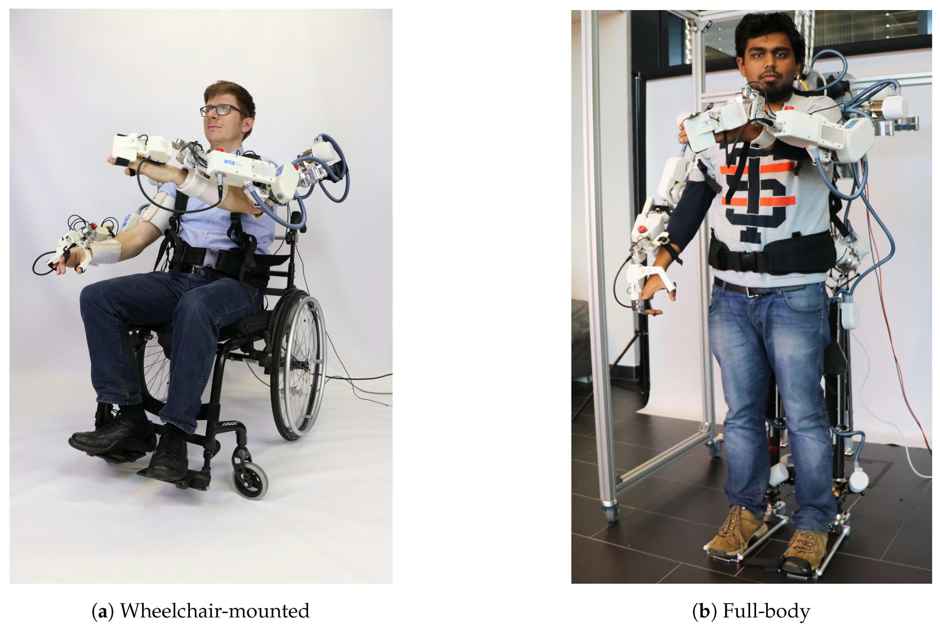
2. Mechatronic System Design
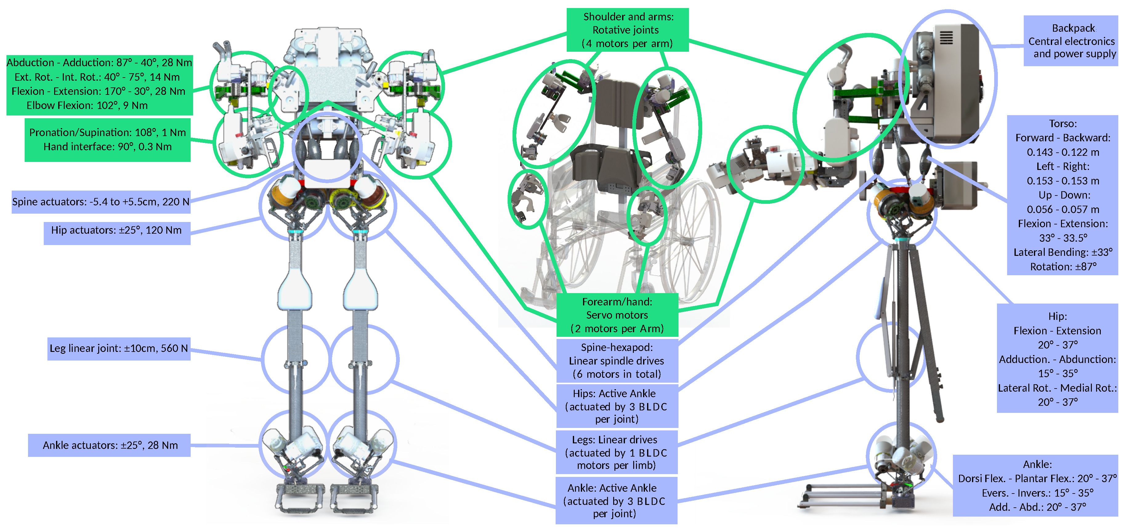
2.1. Mechanical Design
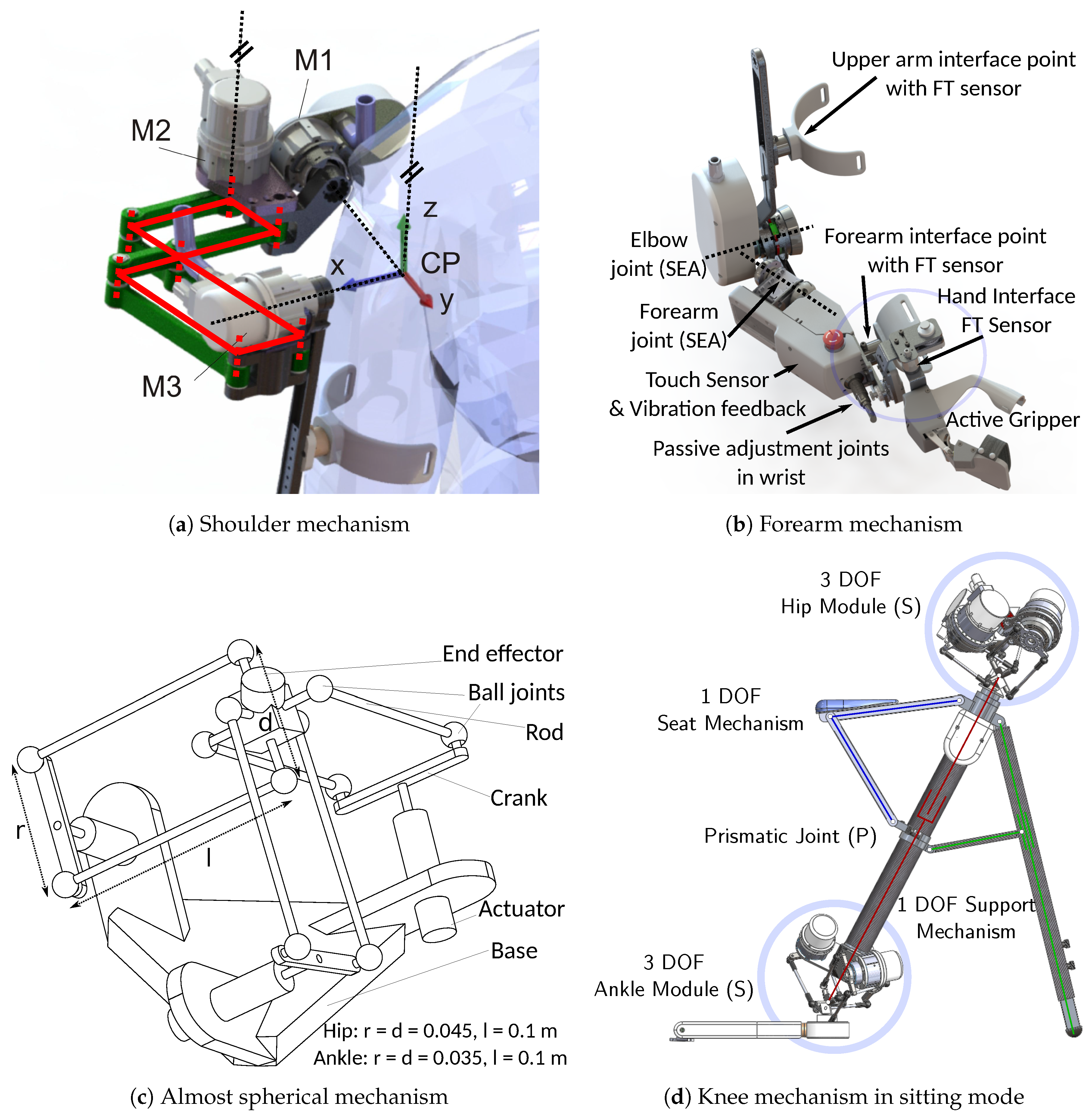
2.1.1. Sub-Mechanism Modules
Shoulder Mechanism Design
Forearm and Elbow
Hip and Ankle Joints
Knee Joint
Torso Joint
2.1.2. Safety Aspects
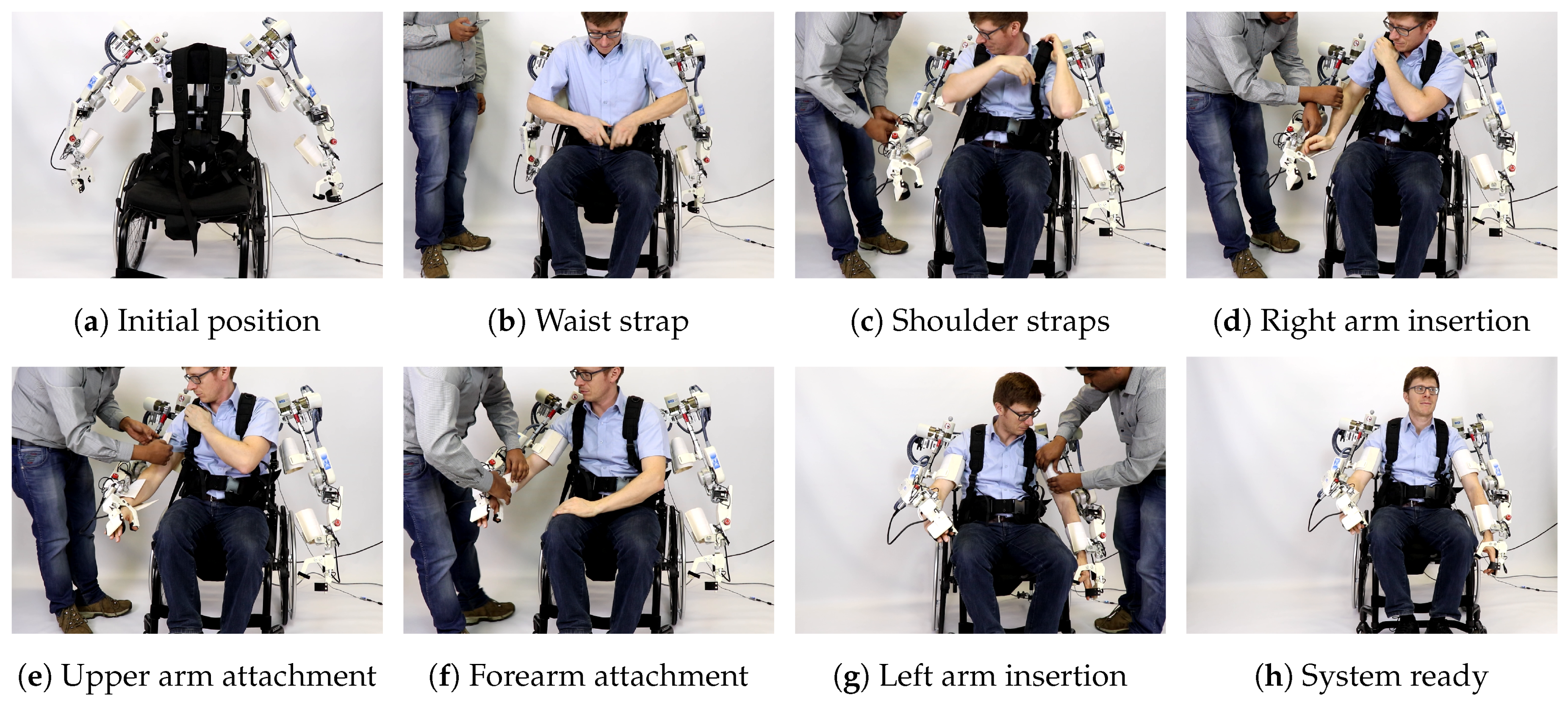
2.1.3. Interface with Human
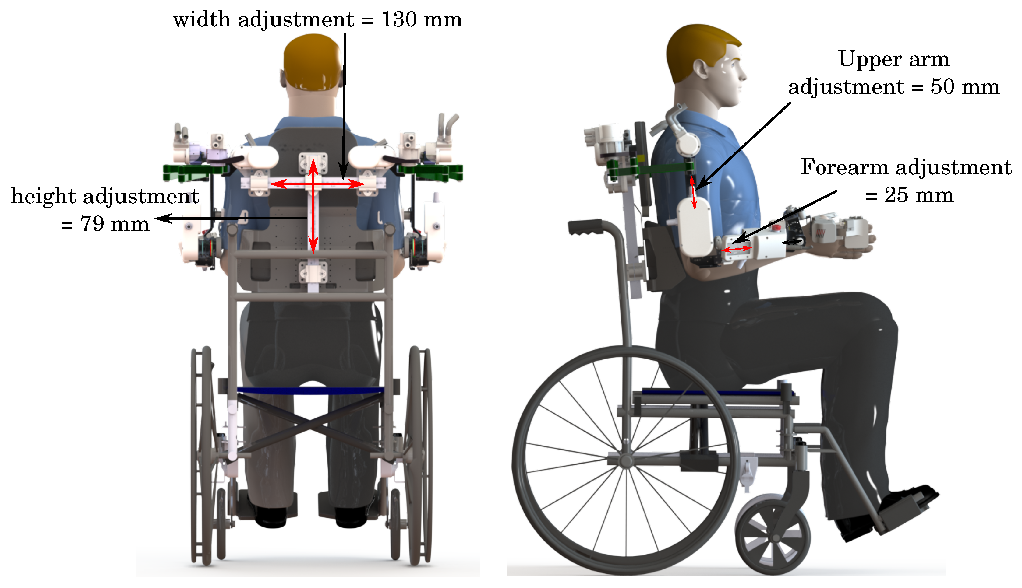
2.1.4. Adaption to Different Human Sizes
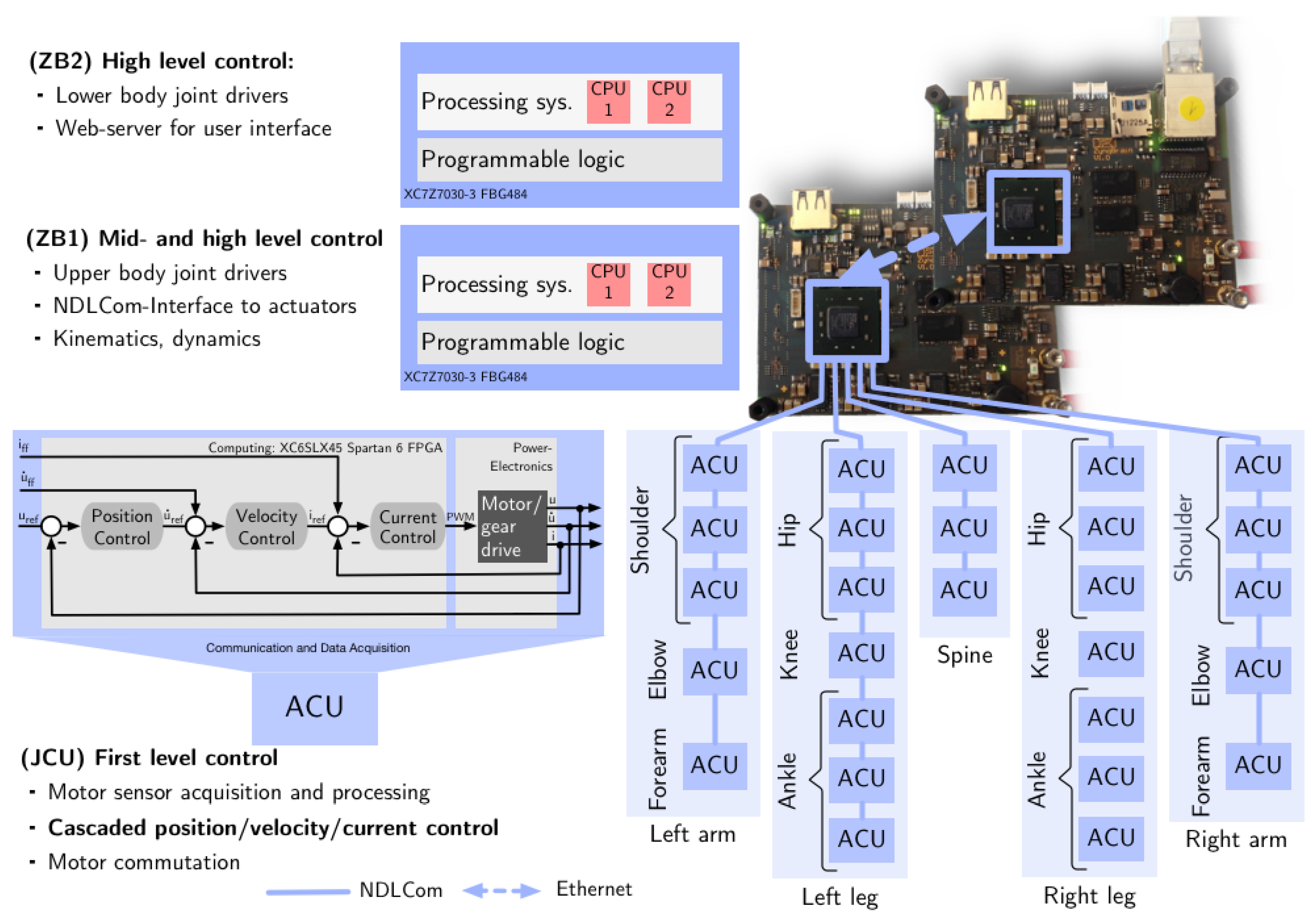
2.2. Electronic Design and Processing Architecture
2.2.1. Decentralized Actuator-Level Controllers
2.2.2. Central Electronics for Mid- and High-Level Control
2.2.3. Power Management
2.2.4. Safety Aspects
3. Exoskeleton Modeling and Control for Rehabilitation Therapies
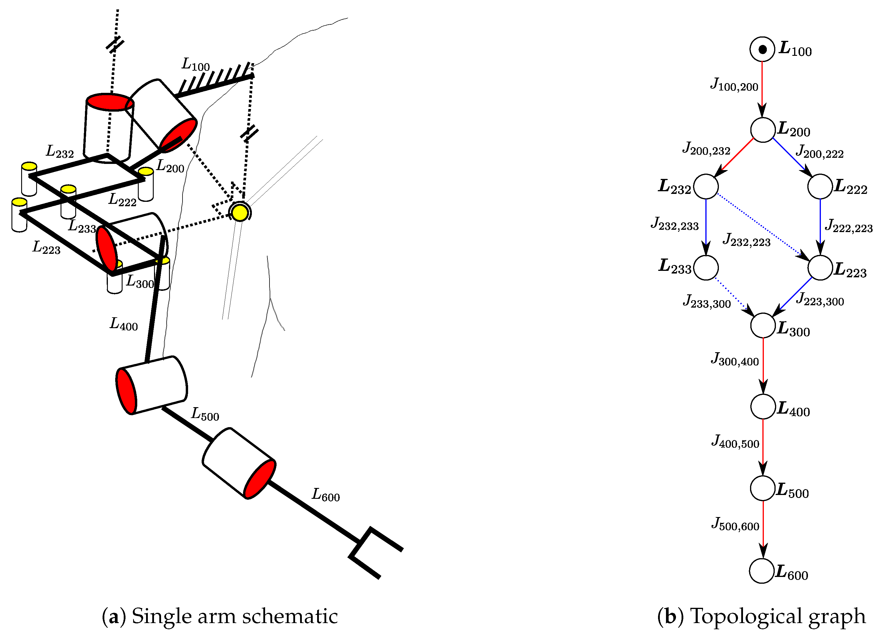
3.1. Kinematic and Dynamic Modeling
- spanning tree joints (): all the joints belonging to the spanning tree chosen by regular numbering scheme,
- independent joints (): a set of independent variables selected such that defines uniquely,
- active joints (): all the joints that contain the actuators
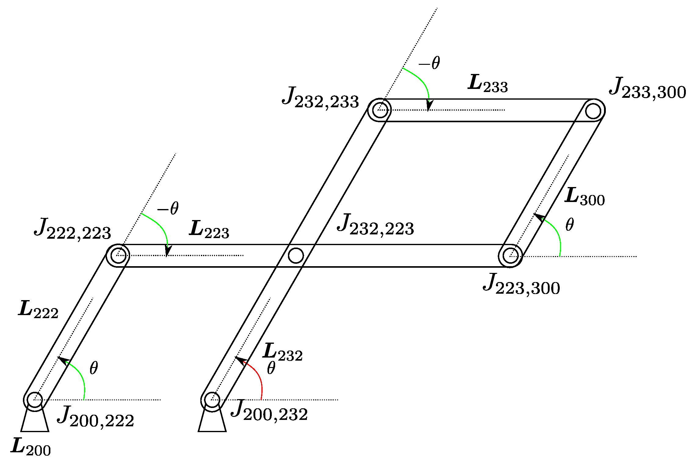
3.1.1. Loop Closure Functions
Example of Loop Closure Function of Recupera Single Arm
3.1.2. Equations of Motion (EOM)
3.2. Exoskeleton Control
3.2.1. First-Level Control
3.2.2. Mid-Level Control
3.2.3. High-Level Control
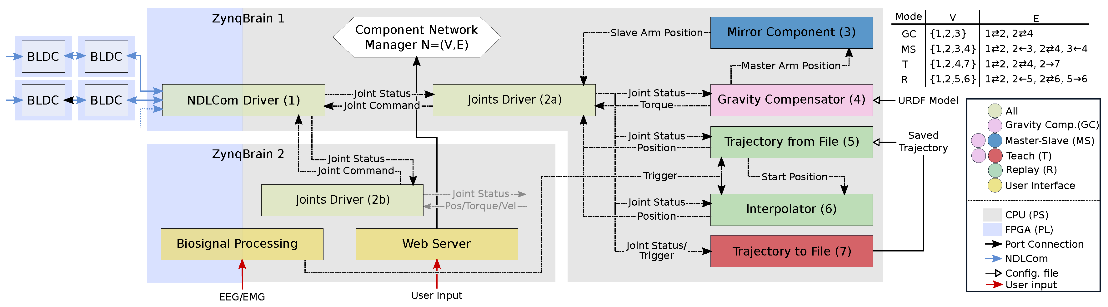
3.3. Software Design
4. Results and Discussion
4.1. Gravity Compensation Mode
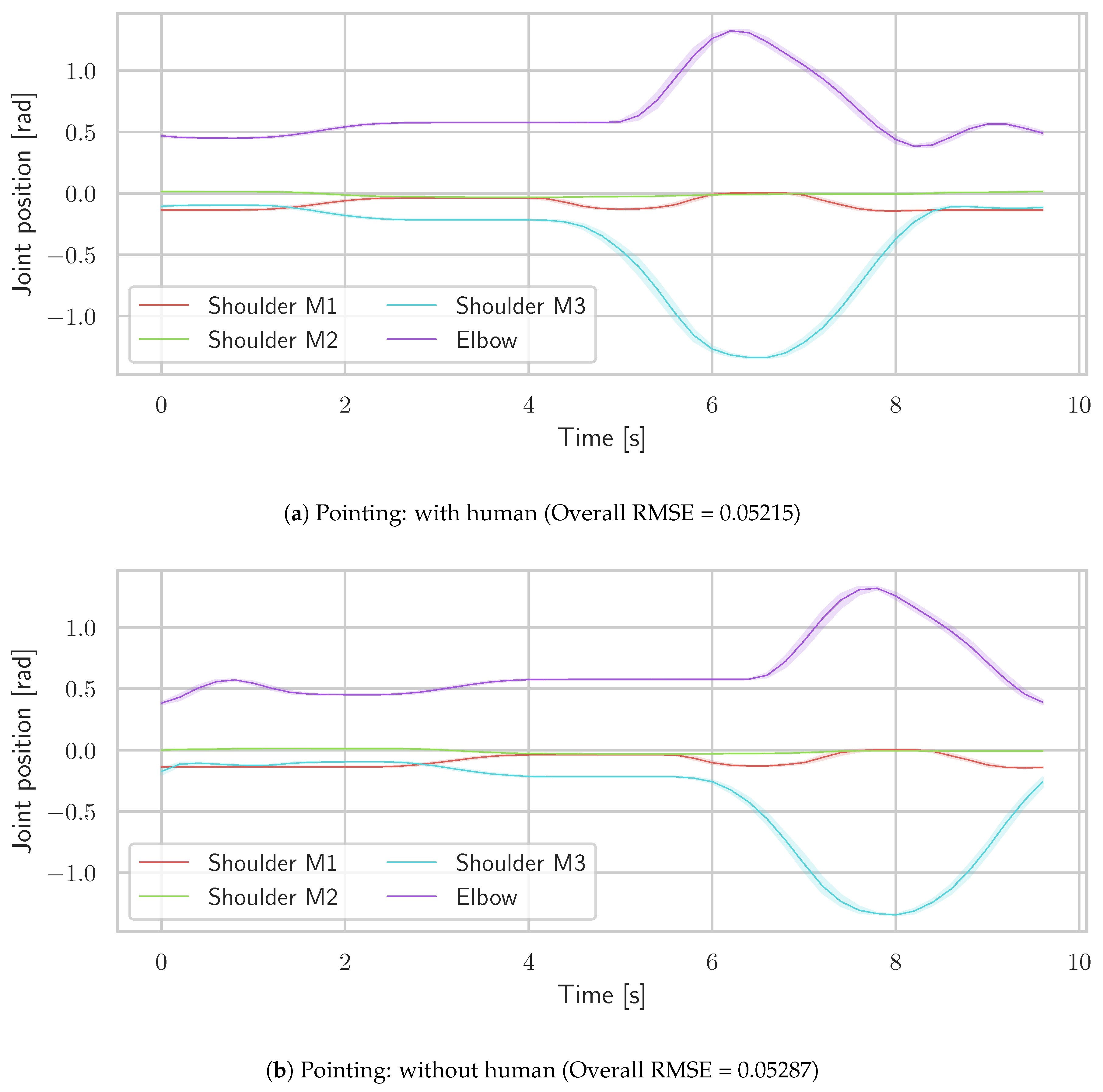
4.2. Teach & Replay Mode
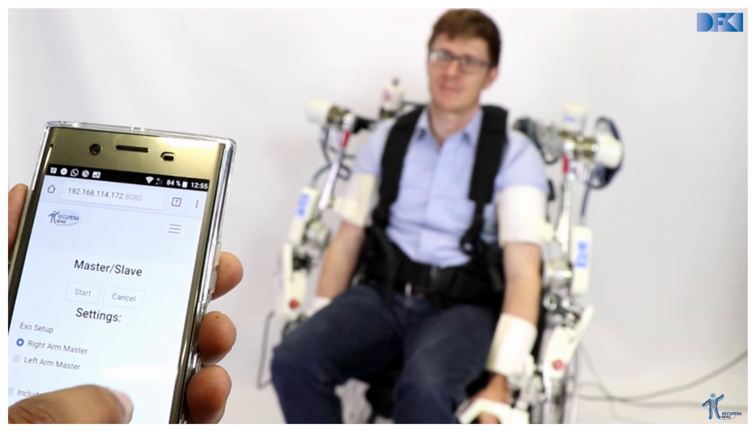
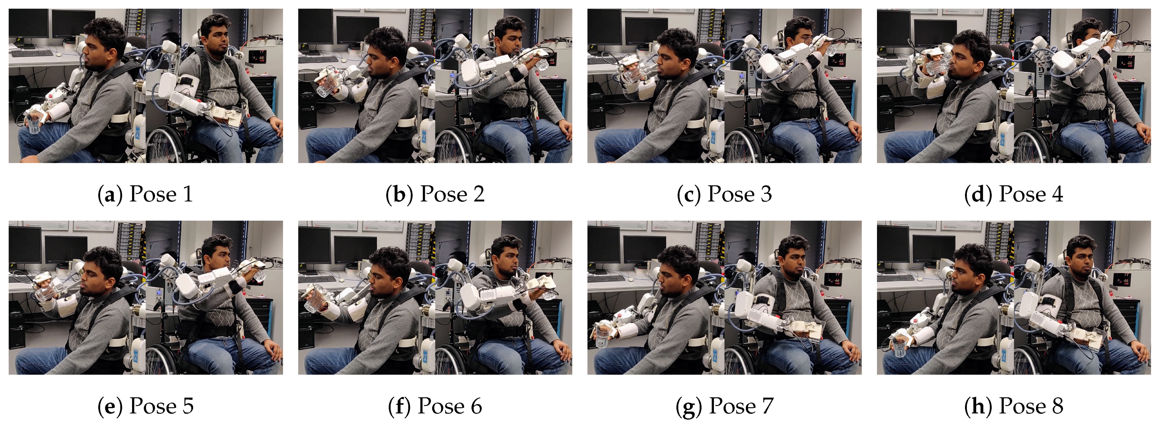
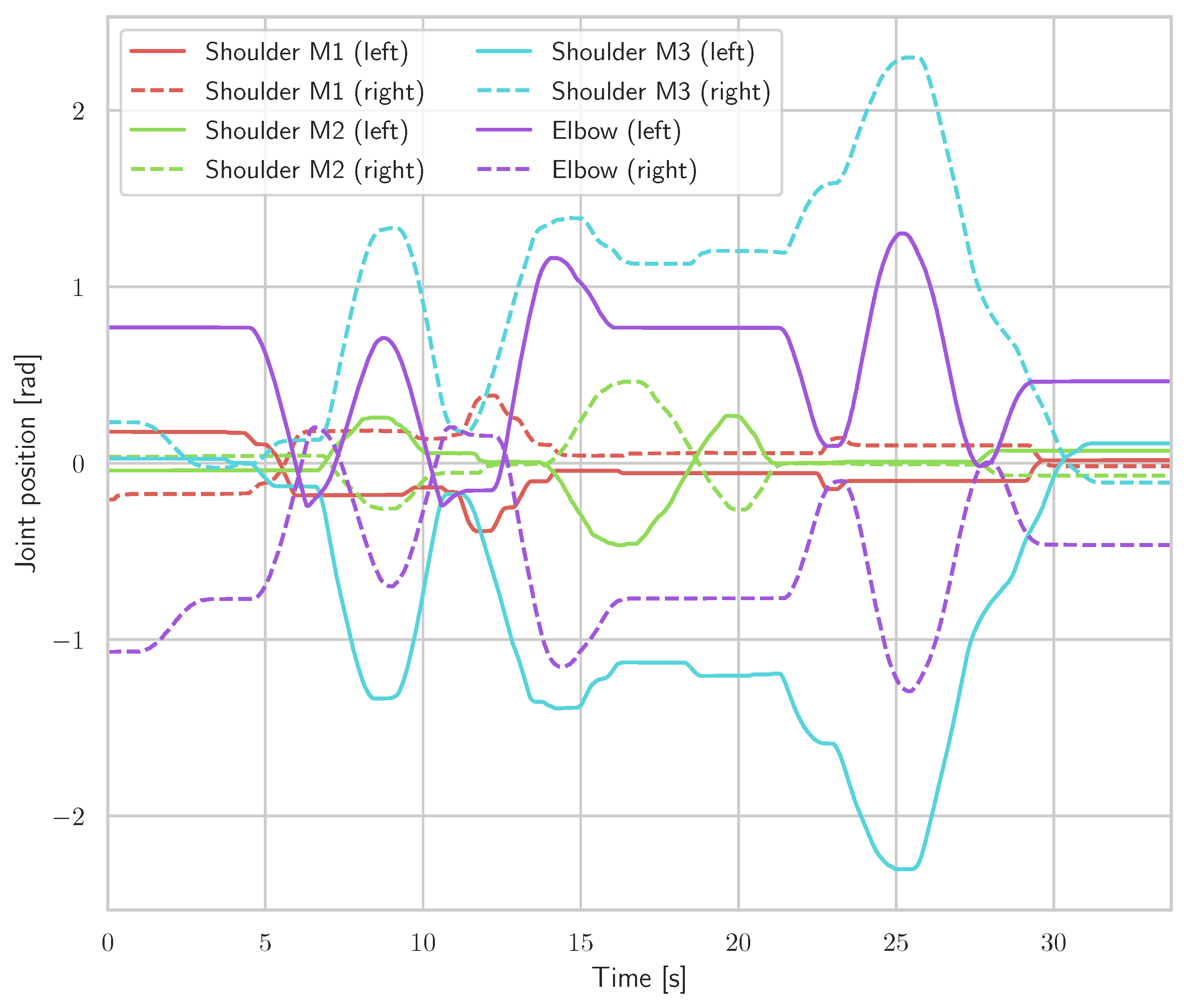
4.3. Master-Slave Mode
4.4. Comparison with Similar Exoskeleton Systems
5. Conclusions
Supplementary Materials
Author Contributions
Funding
Acknowledgments
Conflicts of Interest
References
- Global Burden of Disease (GBD). Global, regional, and national life expectancy, all-cause mortality, and cause-specic mortality for 249 causes of death. Lancet 2015, 388. [Google Scholar] [CrossRef]
- Günster, C. Schlaganfallversorgung in Deutschland–Inzidenz, Wiederaufnahmen, Mortalität und Pflegerisiko im Spiegel von Routinedaten. Versorgungsreport 2011, 147, 260–268. [Google Scholar]
- Ward, A.; Payne, K.; Caro, J.; Heuschmann, P.; Kolominsky-Rabas, P. Care needs and economic consequences after acute ischemic stroke: The Erlangen Stroke Project. Eur. J. Neurol. 2005, 12, 264–267. [Google Scholar] [CrossRef] [PubMed]
- Walbert, T.; Reese, J.P.; Dodel, R. Krankheitskosten neurologischer Erkrankungen in Deutschland. Nervenheilkunde 2007, 26, 260–268. [Google Scholar] [CrossRef]
- Kwakkel, G.; Kollen, B.J.; Krebs, H.I. Effects of robot-assisted therapy on upper limb recovery after stroke: A systematic review. Neurorehabil. Neural Repair 2008, 22. [Google Scholar] [CrossRef] [PubMed]
- Johansson, B.B. Brain plasticity and stroke rehabilitation: The Willis lecture. Stroke 2000, 31, 223–230. [Google Scholar] [CrossRef] [PubMed]
- Hara, Y. Brain Plasticity and Rehabilitation in Stroke Patients. J. Nippon Med. Sch. 2015, 82, 4–13. [Google Scholar] [CrossRef]
- Langhorne, P.; Coupar, F.; Pollock, A. Motor recovery after stroke: A systematic review. Lancet Neurol. 2009, 8, 741–754. [Google Scholar] [CrossRef]
- Lohse, K.R.; Lang, C.E.; Boyd, L.A. Is more better? Using metadata to explore dose—Response relationships in stroke rehabilitation. Stroke 2014, 45, 2053–2058. [Google Scholar] [CrossRef]
- Krebs, H.I.; Volpe, B.T.; Aisen, M.L.; Hening, W.; Adamovich, S.; Poizner, H.; Subrahmanyan, K.; Hogan, N. Robotic Applications in Neuromotor Rehabilitation. Robotica 2003, 21, 3–11. [Google Scholar] [CrossRef]
- Hogan, N.; Krebs, H. Physically interactive robotic technology for neuromotor rehabilitation. Prog. Brain Res. 2011, 192, 59–68. [Google Scholar] [CrossRef] [PubMed]
- Lo, A.C.; Guarino, P.D.; Richards, L.G.; Haselkorn, J.K.; Wittenberg, G.F.; Federman, D.G.; Ringer, R.J.; Wagner, T.H.; Krebs, H.I.; Volpe, B.T.; et al. Robot-Assisted Therapy for Long-Term Upper-Limb Impairment after Stroke. N. Engl. J. Med. 2010, 362, 1772–1783. [Google Scholar] [CrossRef] [PubMed]
- Maciejasz, P.; Eschweiler, J.; Gerlach-Hahn, K.; Jansen-Troy, A.; Leonhardt, S. A survey on robotic devices for upper limb rehabilitation. J. NeuroEng. Rehabil. 2014, 11, 1–29. [Google Scholar] [CrossRef]
- Proietti, T.; Crocher, V.; Roby-Brami, A.; Jarrassé, N. Upper-Limb Robotic Exoskeletons for Neurorehabilitation: A Review on Control Strategies. IEEE Rev. Biomed. Eng. 2016, 9, 4–14. [Google Scholar] [CrossRef] [PubMed]
- Gopura, R.; Bandara, D.; Kiguchi, K.; Mann, G. Developments in hardware systems of active upper-limb exoskeleton robots: A review. Robot. Auton. Syst. 2016, 75, 203–220. [Google Scholar] [CrossRef]
- Gassert, R.; Dietz, V. Rehabilitation robots for the treatment of sensorimotor deficits: A neurophysiological perspective. J. NeuroEng. Rehabil. 2018, 15, 46. [Google Scholar] [CrossRef] [PubMed]
- Lo, H.S.; Xie, S.Q. Exoskeleton robots for upper-limb rehabilitation: State of the art and future prospects. Med. Eng. Phys. 2012, 34, 261–268. [Google Scholar] [CrossRef]
- Ada, L.; Dorsch, S.; Canning, C.G. Strengthening interventions increase strength and improve activity after stroke: A systematic review. Aust. J. Physiother. 2006, 52, 241–248. [Google Scholar] [CrossRef]
- Kwakkel, G.; Wagenaar, R.C.; Twisk, J.W.; Lankhorst, G.J.; Koetsier, J.C. Intensity of leg and arm training after primary middle-cerebral-artery stroke: A randomised trial. Lancet 1999, 354, 191–196. [Google Scholar] [CrossRef]
- Wu, X.; Guarino, P.; Lo, A.C.; Peduzzi, P.; Wininger, M. Long-term effectiveness of intensive therapy in chronic stroke. Neurorehabil. Neural Repair 2016, 30, 583–590. [Google Scholar] [CrossRef]
- Dijkers, M.; deBear, P.; Erlandson, R.; Kristy, K.; Geer, D.; Nichols, A. Patient and staff acceptance of robotic technology in occupational therapy: A pilot study. J. Rehabil. Res. Dev. 1991, 28, 33–44. [Google Scholar] [CrossRef] [PubMed]
- Krebs, H.I.; Hogan, N.; Aisen, M.L.; Volpe, B.T. Robot-aided neurorehabilitation. IEEE Trans. Rehabil. Eng. 1998, 6, 75–87. [Google Scholar] [CrossRef] [PubMed]
- Basteris, A.; Nijenhuis, S.M.; Stienen, A.H.A.; Buurke, J.H.; Prange, G.B.; Amirabdollahian, F. Training modalities in robot-mediated upper limb rehabilitation in stroke: A framework for classification based on a systematic review. J. Neuroeng. Rehabil. 2014, 11, 111. [Google Scholar] [CrossRef] [PubMed]
- Bertani, R.; Melegari, C.; Maria, C.; Bramanti, A.; Bramanti, P.; Calabrò, R.S. Effects of robot-assisted upper limb rehabilitation in stroke patients: A systematic review with meta-analysis. Neurol. Sci. 2017, 38, 1561–1569. [Google Scholar] [CrossRef]
- Lo, K.; Stephenson, M.; Lockwood, C. Effectiveness of robotic assisted rehabilitation for mobility and functional ability in adult stroke patients: A systematic review. JBI Database Syst. Rev. Implement. Rep. 2017, 15, 3049–3091. [Google Scholar] [CrossRef] [PubMed]
- Esquenazi, A.; Talaty, M.; Packel, A.; Saulino, M. The ReWalk powered exoskeleton to restore ambulatory function to individuals with thoracic-level motor-complete spinal cord injury. Am. J. Phys. Med. Rehabil. 2012, 91, 911–921. [Google Scholar] [CrossRef] [PubMed]
- Heo, P.; Gu, G.M.; Lee, S.J.; Rhee, K.; Kim, J. Current hand exoskeleton technologies for rehabilitation and assistive engineering. Int. J. Precis. Eng. Manuf. 2012, 13, 807–824. [Google Scholar] [CrossRef]
- Gopura, R.A.R.C.; Kiguchi, K.; Bandara, D.S.V. A brief review on upper extremity robotic exoskeleton systems. In Proceedings of the 2011 6th International Conference on Industrial and Information Systems, Kandy, Sri Lanka, 16–19 August 2011; pp. 346–351. [Google Scholar] [CrossRef]
- Nef, T.; Guidali, M.; Riener, R. ARMin III—Arm therapy exoskeleton with an ergonomic shoulder actuation. Appl. Bionics Biomech. 2009, 6, 127–142. [Google Scholar] [CrossRef]
- Hocoma AG. Technical Data Armeo Power; Rev. 1.2; Hocoma AG: Volketswil, Switzerland, 2018. [Google Scholar]
- Kim, B.; Deshpande, A.D. An upper-body rehabilitation exoskeleton Harmony with an anatomical shoulder mechanism: Design, modeling, control, and performance evaluation. Int. J. Robot. Res. 2017, 36, 414–435. [Google Scholar] [CrossRef]
- Huang, J.; Tu, X.; He, J. Design and Evaluation of the RUPERT Wearable Upper Extremity Exoskeleton Robot for Clinical and In-Home Therapies. IEEE Trans. Syst. Man Cybern. Syst. 2016, 46, 926–935. [Google Scholar] [CrossRef]
- Gopura, R.A.R.C.; Kiguchi, K. Development of a 6DOF Exoskeleton Robot for Human Upper-Limb Motion Assist. In Proceedings of the 2008 4th International Conference on Information and Automation for Sustainability, Colombo, Sri Lanka, 12–14 December 2008. [Google Scholar] [CrossRef]
- Darbois, N.; Guillaud, A.; Pinsault, N. Do Robotics and Virtual Reality Add Real Progress to Mirror Therapy Rehabilitation? A Scoping Review. Rehabil. Res. Pract. 2018, 2018, 6412318. [Google Scholar] [CrossRef] [PubMed]
- Staubli, P.; Nef, T.; Klamroth-Marganska, V.; Riener, R. Effects of intensive arm training with the rehabilitation robot ARMin II in chronic stroke patients: Four single-cases. J. NeuroEng. Rehabil. 2009, 6, 46. [Google Scholar] [CrossRef] [PubMed]
- Kirchner, E.A.; Will, N.; Simnofske, M.; Benitez, L.M.V.; Bongardt, B.; Krell, M.M.; Kumar, S.; Mallwitz, M.; Seeland, A.; Tabie, M.; et al. Recupera-Reha: Exoskeleton Technology with Integrated Biosignal Analysis for Sensorimotor Rehabilitation. In Proceedings of the Transdisziplinäre Konferenz SmartASSIST, Hamburg, Germany, 12–13 December 2016; pp. 504–517. [Google Scholar]
- Simnofske, M.; Kumar, S.; Bongardt, B.; Kirchner, F. Active Ankle—An Almost-Spherical Parallel Mechanism. In Proceedings of the 47th International Symposium on Robotics (ISR), Munich, Germany, 21–22 June 2016. [Google Scholar]
- Kumar, S.; Bongardt, B.; Simnofske, M.; Kirchner, F. Design and Kinematic Analysis of the Novel Almost Spherical Parallel Mechanism Active Ankle. J. Intell. Robot. Syst. 2018, 1–23. [Google Scholar] [CrossRef]
- Kumar, S.; Simnofske, M.; Bongardt, B.; Müller, A.; Kirchner, F. Integrating Mimic Joints into Dynamics Algorithms: Exemplified by the Hybrid Recupera Exoskeleton. In Proceedings of the Advances in Robotics (AIR ’17), New Delhi, India, 28 June–2 July 2017; ACM: New York, NY, USA, 2017; p. 27. [Google Scholar] [CrossRef]
- Yüksel, M.; Benitez, L.M.V.; Zardykhan, D.; Kirchner, F. Mechatronical design and analysis of a modular developed exoskeleton for rehabilitation purposes. In Proceedings of the 10th International Conference on Electrical and Electronics Engineering (ELECO), Bursa, Turkey, 30 November–2 December 2017; pp. 711–716. [Google Scholar]
- Naidu, D.; Stopforth, R.; Bright, G.; Davrajh, S. A 7 DOF exoskeleton arm: Shoulder, elbow, wrist and hand mechanism for assistance to upper limb disabled individuals. In Proceedings of the AFRICON’11, Livingstone, Zambia, 13–15 September 2011; pp. 1–6. [Google Scholar] [CrossRef]
- Mallwitz, M.; Will, N.; Teiwes, J.; Kirchner, E.A. The CAPIO Active Upper Body Exoskeleton and its Application for Teleoperation. In Proceedings of the 13th Symposium on Advanced Space Technologies in Robotics and Automation (ASTRA-2015), Noordwijk, The Netherlands, 11–13 May 2015. [Google Scholar]
- Magermans, D.; Chadwick, E.; Veeger, H.; Van Der Helm, F. Requirements for upper extremity motions during activities of daily living. Clin. Biomech. 2005, 20, 591–599. [Google Scholar] [CrossRef] [PubMed]
- Simnofske, M. Ausrichtungsvorrichtung zum Ausrichten einer Plattform in drei rotatorischen Freiheiten. German Patent DE102013018034A1, 3 June 2015. [Google Scholar]
- Kong, X.; Gosselin, C.M. Type Synthesis of Parallel Mechanisms, 1st ed.; Springer Publishing Company, Incorporated: Berlin, Germany, 2007. [Google Scholar]
- Kuehn, D.; Schilling, M.; Stark, T.; Zenzes, M.; Kirchner, F. System Design and Field Testing of the Hominid Robot Charlie. J. Field Robot. 2016, 34, 666–703. [Google Scholar] [CrossRef]
- Kuehn, D.; Dettmann, A.; Kirchner, F.; Kirchner, F. Analysis of using an active artificial spine in a quadruped robot. In Proceedings of the 2018 4th International Conference on Control, Automation and Robotics (ICCAR), Auckland, New Zealand, 20–23 April 2018; pp. 37–42. [Google Scholar] [CrossRef]
- iC-MU Magnetic Off-Axis Absolute Position Encoder. Available online: http://www.ichaus.de/ic-mu (accessed on 10 January 2019).
- Xilinx Inc. UG585 Zynq-7000 All Programmable SoC Technical Reference Manual, 1.10 ed.; Xilinx Inc.: San Jose, CA, USA, 2015. [Google Scholar]
- Wöhrle, H.; Tabie, M.; Kim, S.K.; Kirchner, F.; Kirchner, E.A. A Hybrid FPGA-Based System for EEG- and EMG-Based Online Movement Prediction. Sensors 2017, 17, 1552. [Google Scholar] [CrossRef] [PubMed]
- Featherstone, R. Rigid Body Dynamics Algorithms; Springer: Secaucus, NJ, USA, 2007. [Google Scholar]
- Kumar, S.; Nayak, A.; Bongardt, B.; Mueller, A.; Kirchner, F. Kinematic Analysis of Active Ankle Using Computational Algebraic Geometry. In Computational Kinematics; Zeghloul, S., Romdhane, L., Laribi, M.A., Eds.; Springer International Publishing: Cham, Switzerland, 2018; pp. 117–125. [Google Scholar]
- Kumar, S.; von Szadkowski, K.A.; Müller, A.; Kirchner, F. HyRoDyn: A Modular Software Framework for Solving Analytical Kinematics and Dynamics of Series-Parallel Hybrid Robots. In Proceedings of the International Conference on Intelligent Robots and Systems (Late Breaking Poster), Madrid, Spain, 1–5 October 2018. [Google Scholar]
- Flask, Web Development One Drop at a Time. Available online: http://flask.pocoo.org/ (accessed on 21 December 2018).
- Rock, the Robot Construction Kit. Available online: http://www.rock-robotics.org (accessed on 21 December 2018).
- Tabie, M.; Kirchner, E.A. EMG Onset Detection—Comparison of different methods for a movement prediction task based on EMG. In Proceedings of the 6th International Conference on Bio-inspired Systems and Signal Processing (BIOSIGNALS-13); Alvarez, S., Solé-Casals, J., Fred, A., Gamboa, H., Eds.; SciTePress: Barcelona, Spain, 2013; pp. 242–247. [Google Scholar]
- Kirchner, E.A.; Tabie, M.; Seeland, A. Multimodal Movement Prediction—Towards an Individual Assistance of Patients. PLoS ONE 2014, 9, e85060. [Google Scholar] [CrossRef]


| Location | Wheelchair System | Full Body System |
|---|---|---|
| 2× Hand interface | ATI Nano 17 | ATI Nano 17 |
| 2× Forearm | ATI Nano 25 | ATI Nano 25 |
| 2× Upperarm | ATI Nano 25 | ATI Nano 25 |
| 1× Back | - | ATI Nano 25 |
| 1× Hip | - | ATI Nano 25 |
| 2× Foot | - | ATI Nano 25 |
| Location | ACU PCBs | Motor Type | Gear | Speed | Sensors | |
|---|---|---|---|---|---|---|
| Upper body | Shoulder | P, D, C | TQ-Systems Robodrive (RD) | HarmonicDrive (HD) | 330°/s | 2 × A |
| ILM 50x 08 | CPL-14-2A, 100:1 | |||||
| Elbow | P, D, C | Maxon EC-flat 45 | HD HFUC-11-2A, 100:1 | 198°/s | 3 × A | |
| Forearm | D, C | Dynamixel MX28 | 193:1 | 330°/s | 2 × A | |
| Lower body | Spine | 2 × P, D, C | Allied Motion | Ball screw, | 167 mm/s | 2 × A, W |
| HT 01500 M | 1.5 mm pitch | |||||
| Hip | P, D, C | RD ILM 70x 10 | HD CPL-25-2A, 160:1 | 132°/s | A, R | |
| Legs | P, D, C | RD ILM 38x 12 | Ball screw, 2 mm pitch | 266 mm/s | A, R, L | |
| Ankle | P, D, C | RD ILM 50x 08 | HD CPL-14-2A, 100:1 | 330°/s | 2 × A |
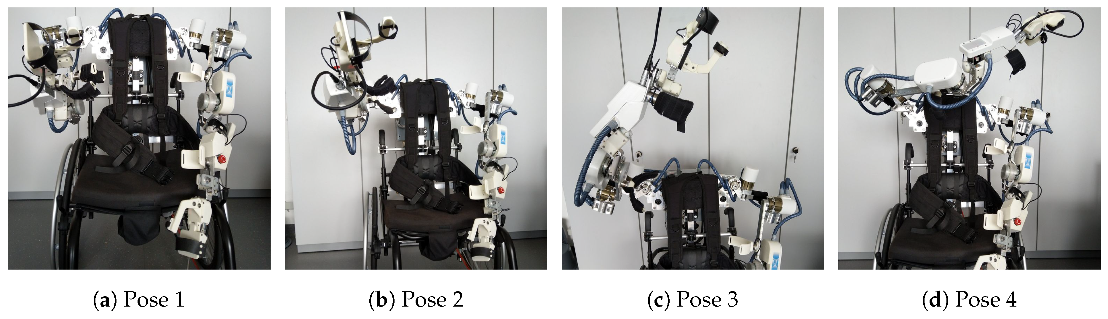
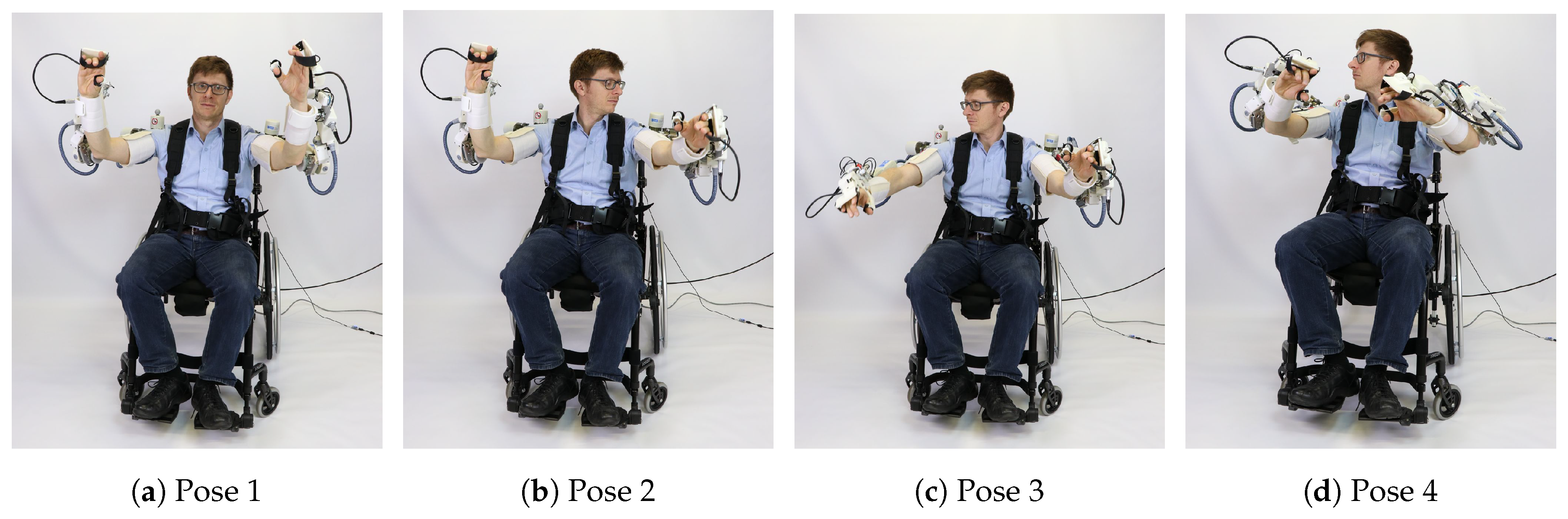
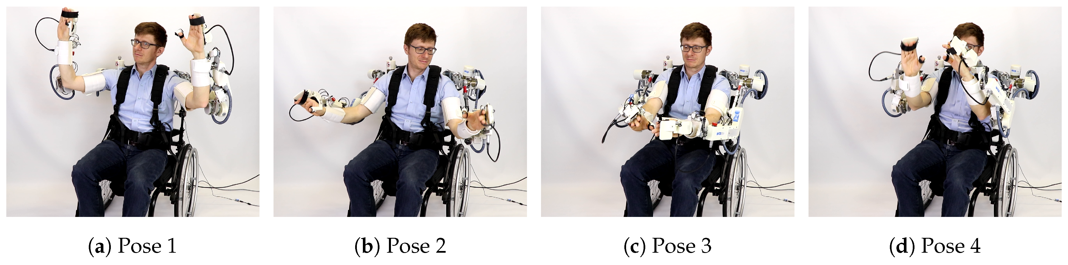
| Pose | Commanded Torque (Nm) | Measured Torque (Nm) | MAE (Nm) | ∥MAE∥ |
|---|---|---|---|---|
| Pose 1 | 0.2631 | |||
| Pose 2 | 0.1536 | |||
| Pose 3 | 0.1162 | |||
| Pose 4 | 0.1435 |
| Device | Recupera | Harmony [31] | ARMIN III [29] | SUEFUL-6 [33] | ADL [31,43] |
|---|---|---|---|---|---|
| Weight (kg) | 8.6 | 31.2 | 18.75 | - | - |
| DOF | 10 | 14 | 4 | 6 | - |
| Bilateral | yes | yes | no | no | - |
| Torso harness | yes | yes | no | no | - |
| Gripper | yes | no | no | no | - |
| Wheelchair | yes | no | no | yes | - |
| Ab./Adduct. (°, Nm) | 87/40(28) | 170/60(34) | 135/47(39) | - | 131/54 |
| Ex./Int. rot. (°, Nm) | 40/75(14) | 79/80(34) | 91/92(33) | 0/90(35) | 76/62 |
| Flex./Ext. (°, Nm) | 170/30(28) | 160/45(34) | 140/46(38) | 0/90(9) | 131/51 |
| Elbow flex. (°, Nm) | 102(9) | 150(13) | 123(32) | 120(9) | 148 |
| Pro/supinat. (°, Nm) | 108(1) | 172(1.25) | - | 140(4) | 167 |
© 2019 by the authors. Licensee MDPI, Basel, Switzerland. This article is an open access article distributed under the terms and conditions of the Creative Commons Attribution (CC BY) license (http://creativecommons.org/licenses/by/4.0/).
Share and Cite
Kumar, S.; Wöhrle, H.; Trampler, M.; Simnofske, M.; Peters, H.; Mallwitz, M.; Kirchner, E.A.; Kirchner, F. Modular Design and Decentralized Control of the Recupera Exoskeleton for Stroke Rehabilitation. Appl. Sci. 2019, 9, 626. https://doi.org/10.3390/app9040626
Kumar S, Wöhrle H, Trampler M, Simnofske M, Peters H, Mallwitz M, Kirchner EA, Kirchner F. Modular Design and Decentralized Control of the Recupera Exoskeleton for Stroke Rehabilitation. Applied Sciences. 2019; 9(4):626. https://doi.org/10.3390/app9040626
Chicago/Turabian StyleKumar, Shivesh, Hendrik Wöhrle, Mathias Trampler, Marc Simnofske, Heiner Peters, Martin Mallwitz, Elsa Andrea Kirchner, and Frank Kirchner. 2019. "Modular Design and Decentralized Control of the Recupera Exoskeleton for Stroke Rehabilitation" Applied Sciences 9, no. 4: 626. https://doi.org/10.3390/app9040626
APA StyleKumar, S., Wöhrle, H., Trampler, M., Simnofske, M., Peters, H., Mallwitz, M., Kirchner, E. A., & Kirchner, F. (2019). Modular Design and Decentralized Control of the Recupera Exoskeleton for Stroke Rehabilitation. Applied Sciences, 9(4), 626. https://doi.org/10.3390/app9040626