Article

Serpens: A Highly Compliant Low-Cost ROS-Based Snake Robot with Series Elastic Actuators, Stereoscopic Vision and a Screw-Less Assembly Mechanism

by
Filippo Sanfilippo
*,
Erlend Helgerud
,
Per Anders Stadheim
and
Sondre Lieblein Aronsen
Department of Science and Industry Systems, University of South-Eastern Norway (USN), Post Box 235, 3603 Kongsberg, Norway
*
Author to whom correspondence should be addressed.
Appl. Sci. 2019, 9(3), 396; https://doi.org/10.3390/app9030396
Submission received: 28 December 2018 / Revised: 19 January 2019 / Accepted: 21 January 2019 / Published: 24 January 2019
(This article belongs to the Special Issue Advanced Mobile Robotics)

Abstract

:
Snake robot locomotion in a cluttered environment where the snake robot utilises a sensory-perceptual system to perceive the surrounding operational environment for means of propulsion is defined as perception-driven obstacle-aided locomotion (POAL). From a control point of view, achieving POAL with traditional rigidly-actuated robots is challenging because of the complex interaction between the snake robot and the immediate environment. To simplify the control complexity, compliant motion and fine torque control on each joint is essential. Accordingly, intrinsically elastic joints have become progressively prominent over the last years for a variety robotic applications. Commonly, elastic joints are considered to outperform rigid actuation in terms of peak dynamics, robustness, and energy efficiency. Even though a few examples of elastic snake robots exist, they are generally expensive to manufacture and tailored to custom-made hardware/software components that are not openly available off-the-shelf. In this work, Serpens, a newly-designed low-cost, open-source and highly-compliant multi-purpose modular snake robot with series elastic actuator (SEA) is presented. Serpens features precision torque control and stereoscopic vision. Only low-cost commercial-off-the-shelf (COTS) components are adopted. The robot modules can be 3D-printed by using Fused Deposition Modelling (FDM) manufacturing technology, thus making the rapid-prototyping process very economical and fast. A screw-less assembly mechanism allows for connecting the modules and reconfigure the robot in a very reliable and robust manner. The concept of modularity is also applied to the system architecture on both the software and hardware sides. Each module is independent, being controlled by a self-reliant controller board. The software architecture is based on the Robot Operating System (ROS). This paper describes the design of Serpens and presents preliminary simulation and experimental results, which illustrate its performance.

1. Introduction

In nature, limbless organisms such as snakes may exploit rocks, stones, branches, obstacles, or other irregularities in the terrain as a means of propulsion to achieve locomotion [1]. This remarkable ability allows biological snakes to be exceptionally adaptable to various types of environments. Snake robots that can replicate this range of behaviour could enable a variety of possible applications for use in challenging real-life operations and hazardous or confined areas that conventional robots (i.e., wheeled, tracked and legged) and humans are unable to access, such as explorations of earthquake-hit areas, pipe inspections for the oil and gas industry, fire-fighting operations, and search-and-rescue activities (SAR) [2,3]. Snake robot locomotion in a cluttered environment where the snake robot utilises a sensory-perceptual system to exploit the surrounding operational space and identifies walls, obstacles, or other external objects for means of propulsion can be defined as perception-driven obstacle-aided locomotion (POAL) [4,5]. The development of POAL is known to be challenging because of the complex interaction between the snake robot and the adjacent cluttered environment [6]. From a control point of view, achieving POAL requires precisely identifying potential push-points and to accurately determine achievable contact reaction forces. Accomplishing this with traditional rigidly-actuated robots is extremely demanding because of the absence of compliance.
Traditional gear-motor-driven actuators are designed and built for industrial automation. These conventional motors commonly actuate stiff linkages while encoders are employed to make position control possible. The control and overall performance of rigidly actuated robots is heavily impacted by actuator dynamics (i.e., masses, reflected inertias, and stiffness) [7]. Rigid actuators transmit high (virtually infinite) mechanical impedance, thus forcing the robot to resist motion when subject to a force. Rigidly actuated robots are also characterised by having a high bandwidth, which forces them to promptly move to commanded positions regardless of what external forces act on their joints. This characteristic is adequate for industrial automation because it allows robots for tracking trajectories in static or mapped environments, i.e., pick-and-place applications, but it is not suitable for robots that interact with unmapped and dynamic environments or need to navigate terrains cluttered with obstacles, such as snake robots. Indeed, conventional rigid actuators are unable to store and release energy or exploit natural dynamics, making them too inefficient or undesired for mobile locomotion applications. Moreover, when considering POAL, the high reflected inertia of traditional gear-motor-driven actuators can cause potential collisions that may damage both the robot and the environment.
To facilitate the control complexity for robots that interact with unmapped and dynamic environments or need to navigate rough terrains cluttered with obstacles, compliant motion and fine torque control on each joint is desirable. Consequently, intrinsically elastic joints have become progressively prominent over the last years for a variety of robotic applications. Commonly, elastic joints are considered to outperform rigid actuation in terms of peak dynamics, robustness, and energy efficiency [8]. Even though a few examples of elastic snake robots exist [9,10], they are generally costly to produce and tailored to custom-made hardware/software components that are not openly available off-the-shelf.
To give researchers a novel snake robot that is inexpensive to manufacture, easily customisable, and fast to fabricate, a newly-designed low-cost, open-source, and highly-compliant multi-purpose modular snake robot with series elastic actuators (SEA) is introduced in this work. The presented snake robot is named Serpens (“the Serpent”, Greek ’Oφις) after the homonym constellation of the northern hemisphere. Serpens is shown in Figure 1. Serpens features compliant torque-controlled actuators and stereoscopic vision. Only low-cost commercial-off-the-shelf (COTS) components are adopted to achieve a sustainable prototyping process. The robot modules can be 3D-printed by using Fused Deposition Modelling (FDM) manufacturing technology [11], thus making the rapid-prototyping process very economical and quick. A screw-less assembly mechanism allows for connecting the modules and for reconfiguring the robot in a very reliable and robust manner. By combining the rapid-prototyping approach with the modular concept, different configurations can be achieved. By using a low-cost sensing approach, functions for torque sensing at the joint level, sensitive collision detection and joint compliant control are possible. The concept of modularity is also applied to the system architecture on both the software and hardware sides. Each module is independent, being controlled by a self-reliant controller board. The software architecture is based on the Robot Operating System (ROS) [12]. The authors intend this work to be the first in a series of open-source designs to be released, and through the contributions of the open-source user community, result in a large number of design modifications and variations available to researchers.
The paper is organised as follows. A review of the related research work is given in Section 2. In Section 3, we focus on the description of the mechanical overview. A software/hardware overview is described in Section 4.6. In Section 5, some preliminary simulation and experimental results are outlined. Finally, conclusions and future works are discussed in Section 6.

2. Related Research Work

To achieve locomotion in a cluttered and irregular terrain, a snake robot must be able to adapt its body motion to the environment. This requires that the robot can sense environment contact forces acting along its body [13]. To the best of our knowledge, the works in [13,14,15,16,17,18] present snake robot designs featuring contact sensing capabilities. However, the vast majority of snake robots that have been designed thus far adopt traditional gear-motor-driven actuators. The fact that these robots employ rigid actuators requires a very high degree of awareness of their surroundings to achieve POAL. When adopting traditional gear-motor-driven actuators, this implies that a very precise mathematical model that includes the interaction between the snake robot and the surrounding operational environment is needed. Furthermore, when considering POAL, the high reflected inertia of rigidly actuated robots can cause possible collisions that may damage both the robot and the environment.
To avoid the risk of rigid collisions, an alternative approach is inspired by the ability of biological mechanisms to accurately achieve compliance (passively and/or by precisely control torque). Based on this idea, series elastic actuators (SEA) were introduced in [19] as a means of achieving compliant motion and force control with traditional gear-motor-driven actuators. Thereafter, the design and control of SEA has been widely exploited in the fields of legged locomotion [20,21], humanoid robots [22] and manipulators [23]. Regarding snake robots, different methods of achieving compliant motion by controlling the torques exerted by the joints of the robot were presented by the Robotics Institute at the Carnegie Mellon University [10,24]. These control strategies are implemented on a snake robot that includes SEA and torque sensing at each joint, and demonstrate compliant locomotion that adapts naturally to the robot’s surrounding terrain. This work is very pragmatic and has shown some success. However, the underlying idea is based on a relatively simplistic oscillation and adaptation of the torque to the surrounding obstacles. We hypothesise that exploiting full knowledge of the robot’s configuration and surrounding environment can be more beneficial and can produce more reliable results with hopefully better performance. Moreover, the proposed robot design adopts financially demanding components and the software is not completely open-source.
To the best of our knowledge, a 3D-printable highly compliant multi-purpose modular robot that features SEA, precise torque control, open software/hardware and a screw-less assembly mechanism has not been released yet.

3. Mechanical Overview

In this section, the mechanical overview of Serpens is depicted by highlighting the selected design principles, the mechanical design, the proposed screw-less assembly mechanism and the adopted series elastic actuators.

3.1. Design Principles

The module-design of Serpens is inspired by the following principles:
  • Principle of minimalism. To make the robot inexpensive, easily customisable, and fast to fabricate, each module is equipped with the simplest mechanical structure, the minimum number of actuators (only a single SEA per module with one degree of freedom (DOF) and the simplest set of sensors. During the design process, the main focus is to keep the amount of parts as low as possible, and at the same time minimise the number of assembly operations.
  • Principle of symmetry. To facilitate the interaction with the environment, a symmetric design is adopted for each module with a flat profile for the interaction with the terrain. The symmetric design is also selected to store and release energy in a balanced manner.
  • Screw-less assembly mechanism. To ease the connection and reconfiguration of the robot modules, a screw-less assembly mechanism is designed in a very reliable and robust manner.

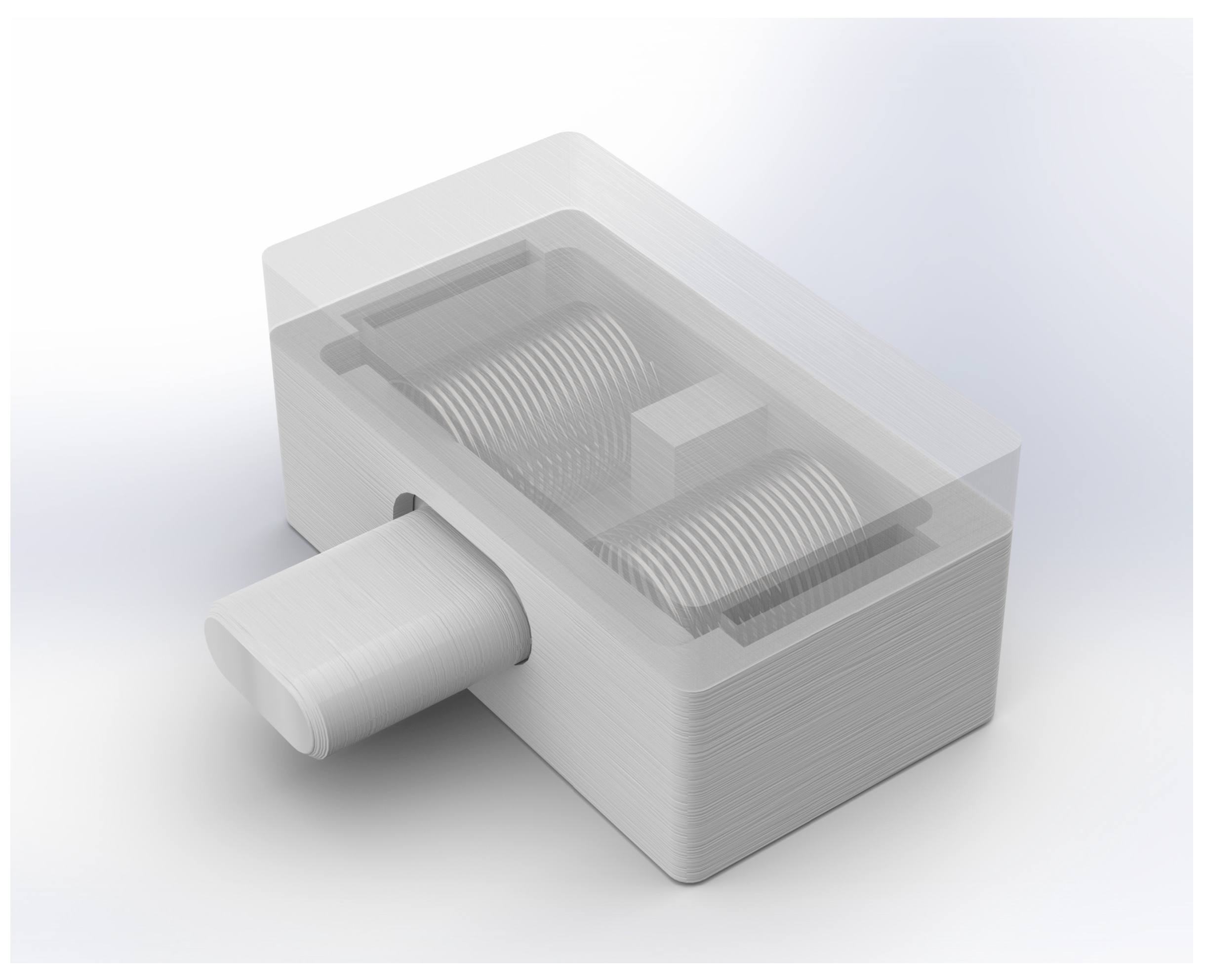
3.2. Mechanical Design

The construction of Serpens consists of similarly designed modules that are shown in Figure 2 and include a head module, a varying number of joint modules, and a tail module. The head module contains an Intel RealSense D435 stereoscopic camera [25]. The tail module only contains an anchorage mechanism for the external power supply cable. The joint module of Serpens is characterised by the parameters summarised in Table 1.

3.3. Estimated Production Cost

The estimated production cost for the joint module is 250 USD, including the following elements:
  • 3D-printing cost;
  • cost of COTS mechanical parts (e.g., springs, nuts, bolts, bearings); and
  • electrical components (e.g., micro-controller, sensors, and actuator).
As shown in Figure 3, Serpens allows for realising different connections, such as pitch connection, yaw connection and pitch–yaw connection.
The pitch connection allows Serpens to move only in 1D, forward or backward. The yaw-connecting configuration makes it possible to move Serpens similar to real snakes with all the joints rotate around the yaw axis. The pitch–yaw-connecting configuration enables Serpens to have some modules that rotate around the pitch axis and others around the yaw axis, respectively. This makes it possible to achieve new locomotion capabilities, such as sidewinding, rotating and rolling [26].
An exploded view of the joint module design is shown in Figure 4. To strengthen the modular attributes of Serpens through a generic and reusable module-design, each joint module is fitted with a screw-less assembly mechanism, a micro-controller, an actuator, an elastic gear, a rotary encoder, a bearing mechanism and a battery-pack. The proposed design enables the assembly process to be performed in an uncritical manner with respect to ordering and rotation of joints, while contributing to a better weight distribution throughout the body.

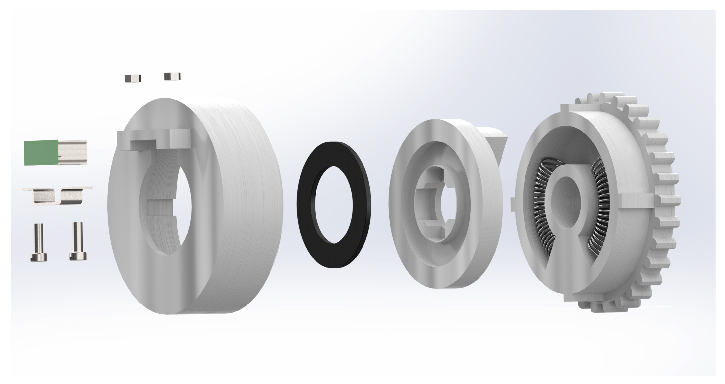
3.4. Screw-Less Assembly Mechanism

As shown in Figure 5, a screw-less assembly mechanism is proposed for Serpens to easily interconnect each joint module through the adoption of specifically designed push-buttons. Each button consists of two springs that locks an oval cylinder in place when triggered. This novel mechanism makes it easier to access the battery-pack and the micro-controller of each module without requiring any tools. A complete dismantling of the modules is easily achievable in a very short time with the removal of just a few screws.

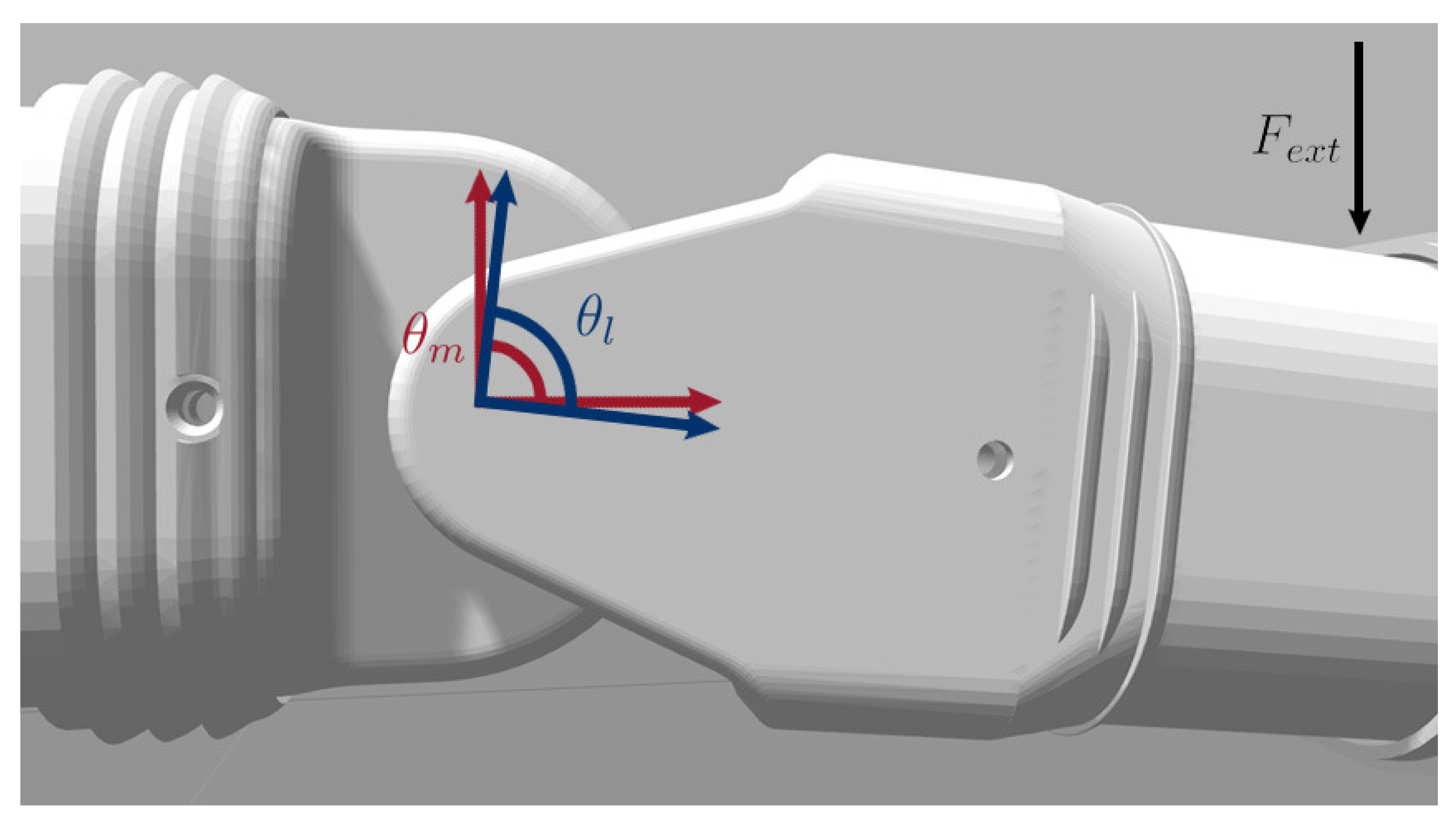
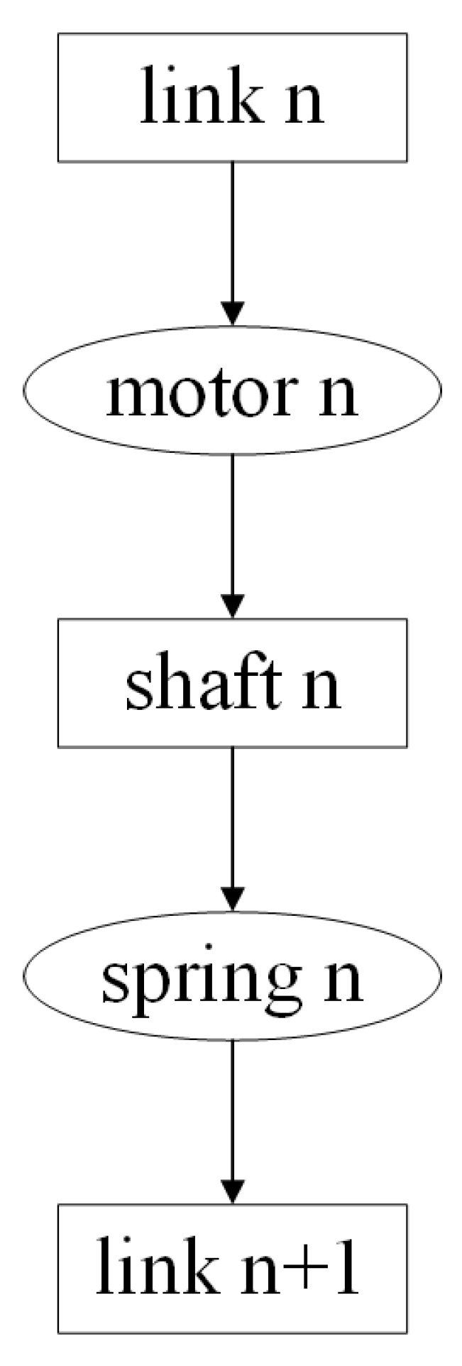
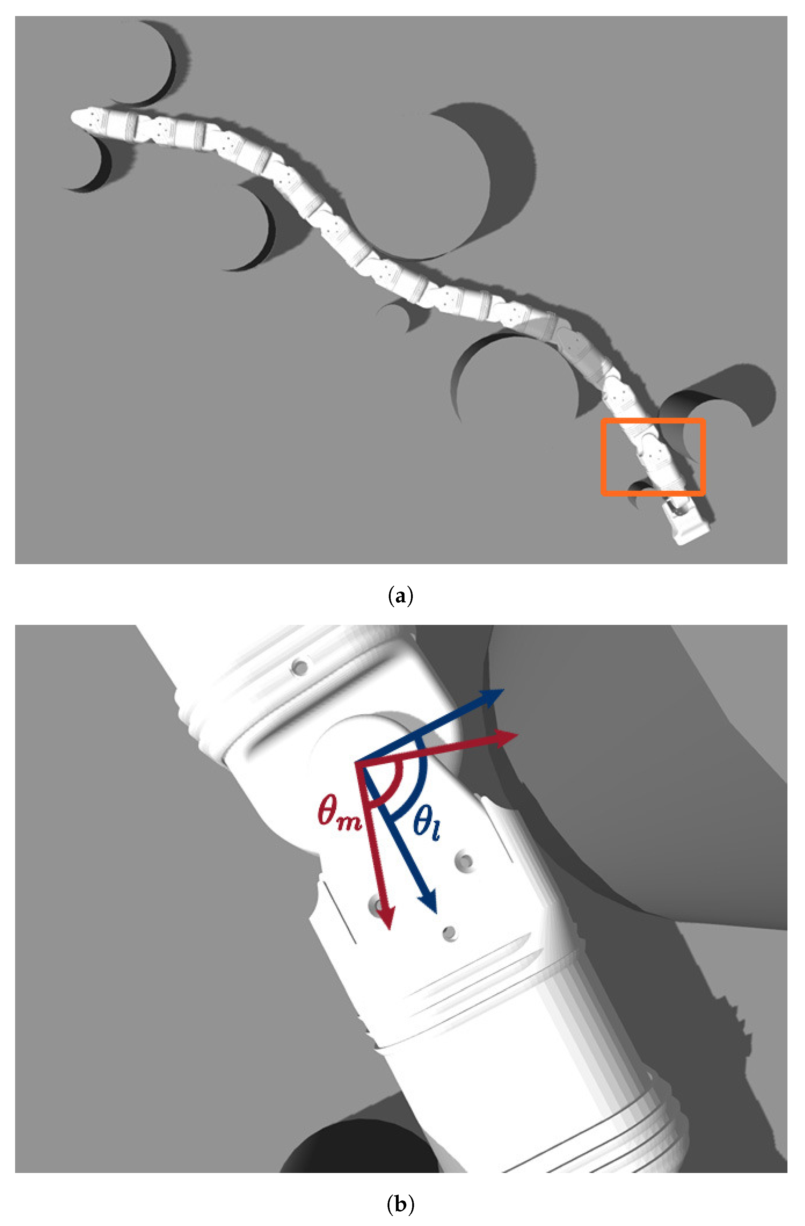
3.5. Series Elastic Actuator (SEA)

To make Serpens highly-compliant with the environment, a newly designed series elastic actuator (SEA) is embedded in each joint module. This makes it possible to achieve passively-compliant motion and precise torque-control. Each SEA deliberately introduces compliance via a spring between the motor-gearbox and the load [27], therefore achieving intrinsic low impedance. As shown in Figure 6, the design of the elastic gear consists of a housing case, a base, a shaft, and a cogwheel. The intermediate element is connected to the shaft and works as a transmission between the cogwheel and the shaft itself. The cogwheel and the actuator are connected through a gear mechanism, where passive-compliance is provided by placing compression springs on each side of the outset of the base, in the chamber of the cogwheel. Even though the spring stiffness can be considered linear within a certain range, an encoder is employed to precisely monitor the misalignment/deviation of the compliant mechanism.
The novel design of Serpens is exclusively based on a 3D-printing process with polylactic acid (PLA) through FDM with the exception of a limited number of elements such as springs, nuts, bolts, bearings and electrical components. One of the main benefits of using PLA is that a relatively high strength construction can be achieved compared to the production cost. In addition, 3D-printing with PLA allows obtaining a reliable rapid-prototyping process by offering a wide range of customisation for different printing-parameters, such as print-speed, wall-thickness and layer-height. This makes it possible to tune the printing process according to the different parts and the properties the parts should hold.

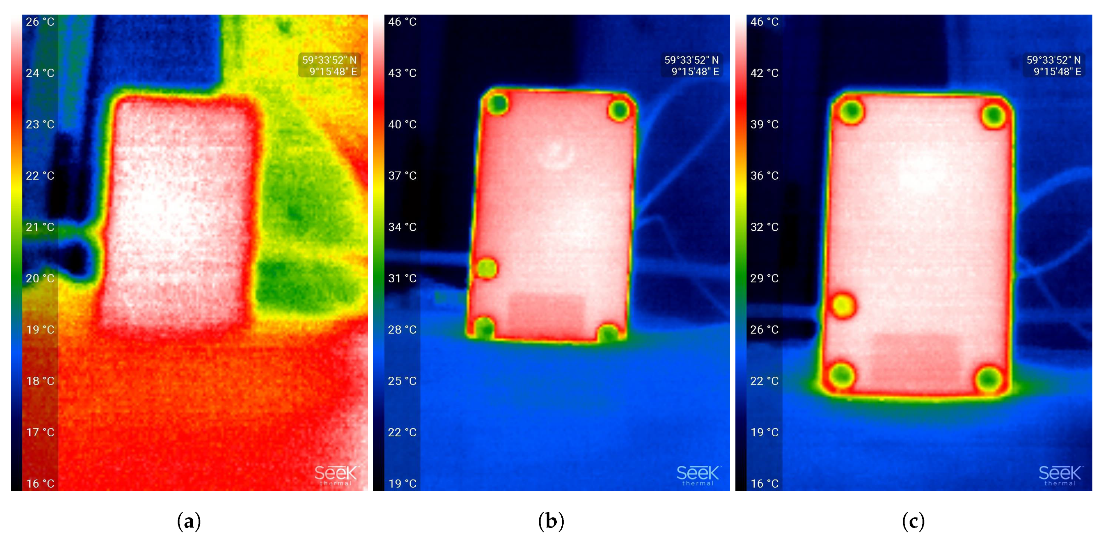
3.6. Heat Dissipation

Within the joint module enclosure, continuous heat generation from the servos might cause overheating and failure. Moreover, the PLA material has poor heat conductivity capabilities (0.13 W/mK) and continuous locomotion could eventually lead to high temperatures within the joint module. To minimise this risk of overheating, the Dynamixel XM430W-210T, a COTS actuator produced by ROBOTIS [28], is selected to actuate each joint module. Each actuator is enclosed in an aluminium casing providing a good rate of heat transfer. As shown in Figure 4, each actuator is fixed to a specifically designed element which allows the surface area to remain exposed to the climate inside the module. The heat transfer performance of the selected actuator is qualitatively shown in Figure 7 by using a heat map. The motor was run for 50 min at a constant velocity of approximately 57.25 RPM. The servo was run without load continuously in one direction and monitored at 0 min, 25 min and 50 min, respectively. This qualitative experiment shows reasonable heat dissipation even after a medium/long running time. Extensive testing with different loads is still needed to assess the heat performance of Serpens in a real operational scenario.

4. Software/Hardware Overview

4.1. Open-Source Software

In line with the overall low-cost approach of Serpens, an open-source software framework is designed for the low-level control. To design the software architecture, there are different robotic frameworks and middleware available in recent years [29]. However, the Robot Operating System (ROS) [12] has emerged as a de facto standard for robot software architecture in the research community. ROS is designed as a meta-operating system for robotic applications. The primary goal of ROS is to provide a common platform to make the design of capable robotic applications quicker and easier. Some of the features it provides include hardware abstraction, device drivers, message-passing and package management. In conjunction with ROS, Gazebo 3D simulator [30] can be adopted to accurately and efficiently simulate robots in complex indoor and outdoor environments. Gazebo also provides a robust physics engine, high-quality graphics, and convenient programmatic and graphical interfaces. In this perspective, ROS serves as the interface for the robot model of Serpens, while Gazebo is used to simulate both the robot and its operational environment. In addition to ROS and Gazebo, the RViz (ROS visualisation) [31] tool can be adopted to visualise and monitor sensor information retrieved in real-time from both the simulated scenario as well as from the real world. Another benefit for developers are the ROS community-driven support and the stable release-cycle of distributions (a new version is released every year, while a new long-term support (LTS) version is released every second year). Moreover, ROS offers an excellent interface to hardware components such as different micro-controllers and other peripheral hardware, i.e., actuators and sensors. The choice of ROS for the design of the control architecture makes it possible to extend the modular concept to both the hardware as well as the software of Serpens.

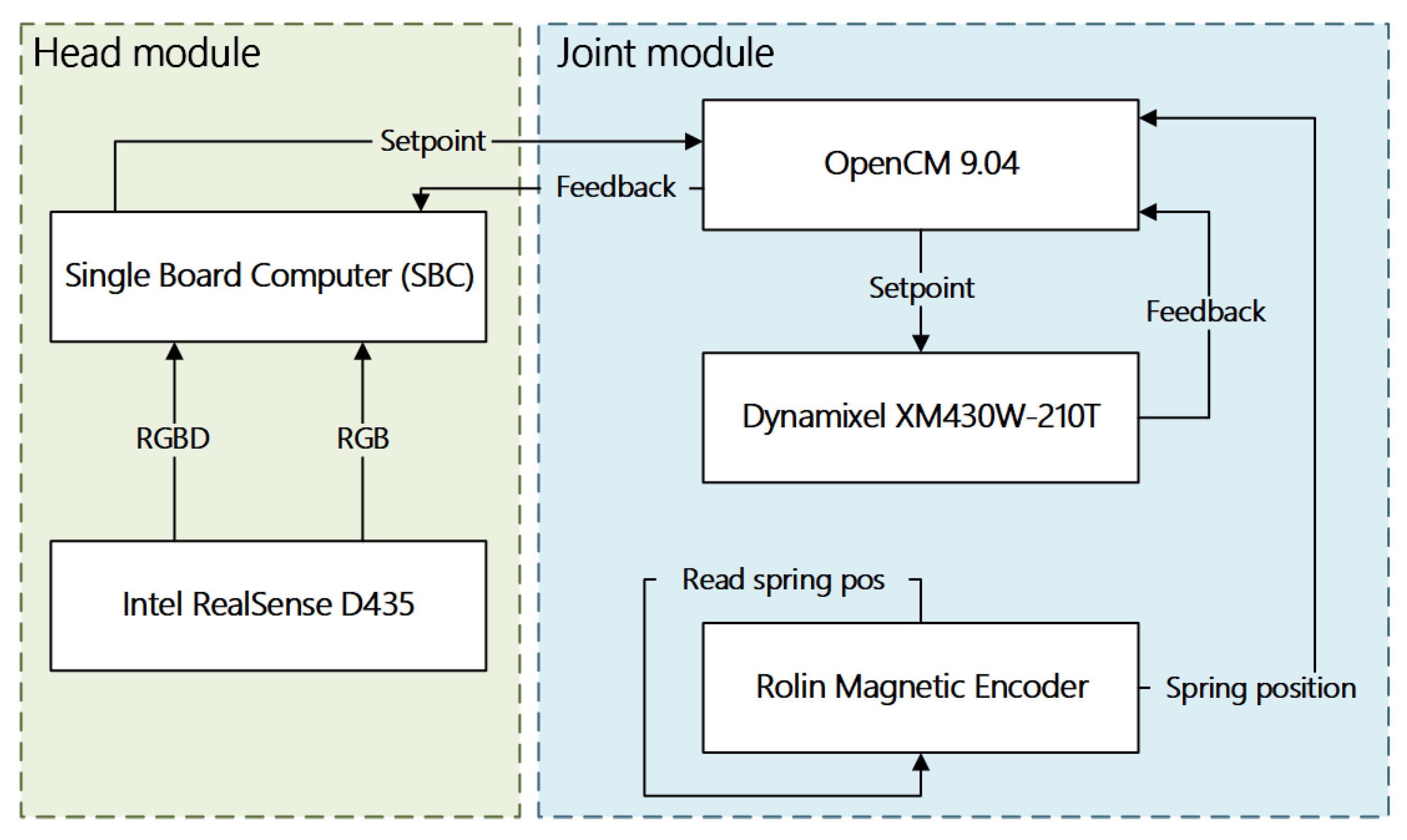
4.2. Hardware Overview

The control of Serpens is dependent on feedback from the actuators regarding position, velocity and torque. This feedback must be provided by the low-level controller of each actuator. Nowadays, there are several COTS actuators available in the market. However, only few commercial options provide precise current-based torque control and profile control for smooth motion planning. For the design of Serpens, the Dynamixel XM430W-210T, a COTS actuator produced by ROBOTIS is selected for each joint module to meet these demanding requirements. This particular actuator provides the aforementioned data as well as additional feedback for temperature and input voltage. In addition to offering the required feedback, the XM430W-210T has a sturdy construction with full-metal gears and a metal body, while being able to deliver a stall torque of 3.0 Nm (at 12.0 V, 2.3 A) in a operating temperature of −5 ~80 [28], which is considered sufficient in regards to the applications and the future development of Serpens. The chosen actuator communicates through a half duplex asynchronous serial Transistor–Transistor Logic (TTL) communication and also facilitate for daisy-chaining, which provides a simple connection structure for multiple actuators.For implementing the low-level control and the interception of feedback, a micro-controller is required at the joint level. Nowadays, different COTS options are available in the market. To facilitate the integration with the ROS-based architecture of Serpens, the ROBOTIS OpenCM 9.04 micro-controller is embedded in each joint module. The OpenCM 9.04 is a 32-bit Cortex-M3 core micro-controller compatible with ROS and with Arduino [32] software/hardware. This choice is also motivated by the limited physical space in the presented design of the joint module, therefore the form-factor of the OpenCM 9.04 (27 mm × 66.5 mm) is a crucial parameter for the selection of this specific micro-controller for Serpens. In addition, since the high-level control can be centralised in a single-board computer (SBC) possibly located either in the head or in an external computer while the low-level control is distributed to the micro-controllers embedded in each joint module, the computing power provided by the OpenCM 9.04 is adequate for designated applications. The interface between the head module and each generic joint module is shown in Figure 8.

4.3. Encoders

The proposed SEA are designed for passive-compliance, as described in Section 3. If the spring stiffness k would be constant, the displacement would be linear with respect to the external forces exerted to the load. Thus, the forces acting on a joint could be estimated by applying Hooke’s law. This can be highlighted in simulation by monitoring the motor- and load-positions and showing that they can be divergent due to external forces acting upon the load, as illustrated in Figure 9. However, in a real-world application, this is not realistic. The spring stiffens can be nonlinear. This is the reason each joint module of Serpens is fitted with a rotary incremental encoder that is connected to the OpenCM 9.04. The encoder is vital to the control of each SEA, as it provides feedback for the absolute position of the load. In particular, a RoLin encoder system is adopted [33] for Serpens. The RoLin component level encoder system consists of a read-head and a magnetised ring. The actuator is a periodically magnetised ring with a pole length of 2 mm. Axial reading of the ring is adopted for Serpens.

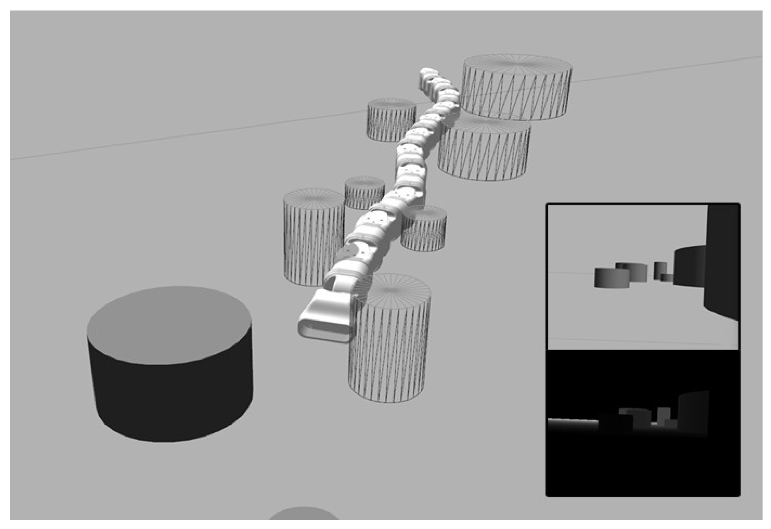
4.4. Single-Board Computer and Stereoscopic Camera

The head-module is fitted with a single-board computer (SBC) and a stereoscopic camera. The SBC is designed to handle all high-level control of Serpens in addition to providing the interface to the camera.
To enable visual feedback of the surroundings of Serpens while traversing unknown terrains, a camera is fitted on the head module. In particular, a reasonably small stereoscopic vision system is embedded because of the limited space in the design and the need for range detection. The proposed solution utilises a standard COTS Intel RealSense D435 [25], a low-cost stereo vision camera comprising two depth sensors, a Red-Green-Blue (RGB) sensor, and a infrared projector. A considerable benefit of the Intel RealSense D435 device is the realsense2_camera [34] package available for ROS, which provides a ROS-compatible interface to the D400-series from Intel, as shown in Figure 10.

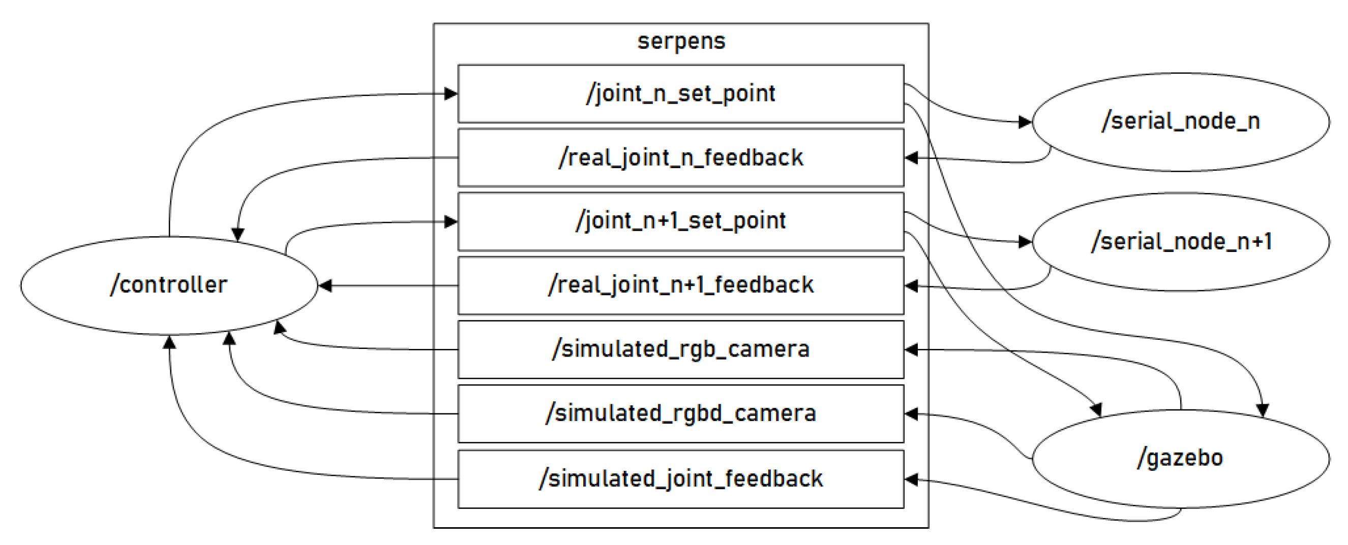
4.5. ROS-Based Low-Level Architecture

The proposed ROS-based software architecture is illustrated by using a node-graph in Figure 11. This shows a simplified view of the nodes and topics used to control n joints of Serpens in the current implementation. The nodes are represented as ellipses while the topics as rectangles. The arrows represent publishers and subscribers, where arrows directed towards an ellipsis or box indicates a subscriber and an arrow directed outwards indicates a publisher.
The controller node can run either on an external computer or the SBC embedded in the head module. This node provides all high-level control for Serpens and acts as a hub for sensory data, such as the depth-sensor data collected by the Intel RealSense D435. As described above in this section, each joint module is provided with an embedded micro-controller (OpenCM 9.04) that is responsible for low-level control of the designated in the structure. Each of the boards acts as separate nodes in the ROS network architecture. In addition to being responsible for the low-level control, each joint module controller board also collects the feedback from the XM 430W-210T actuator and from the RoLin rotary incremental encoder. Each micro-controller implement a running ROS-node. This is shown in Figure 11 as /serial_node_n, where n denotes the micro-controller-index corresponding topics for each joint.

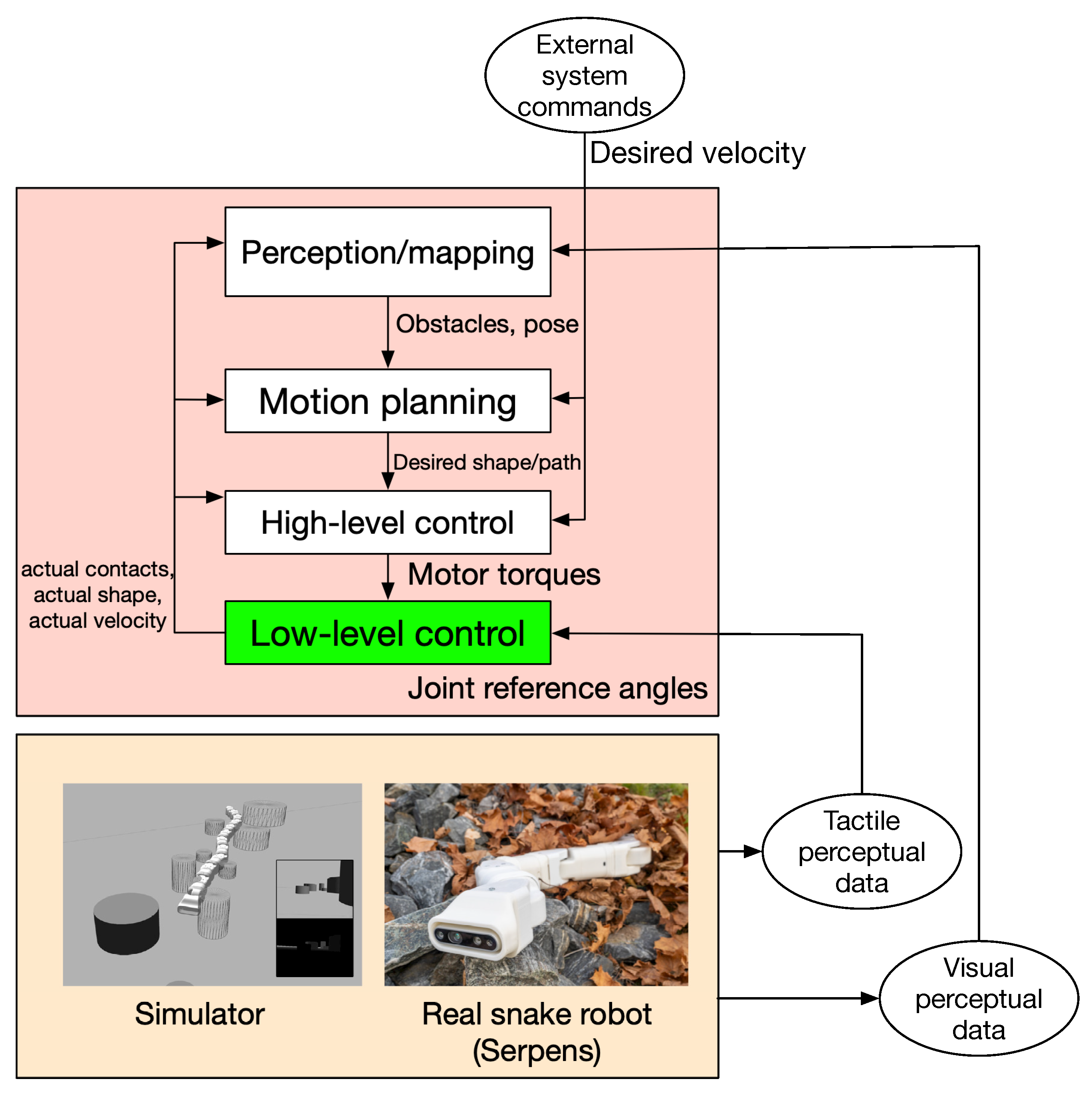
4.6. Guidelines for Designing the Control Framework Architecture to Achieve POAL

In this paper, the fundamental work for implementing the low-level control approach is presented. To practically achieve POAL, a hierarchical control framework is still needed. Possible design guidelines are presented in Figure 12 [2,3]. The following abstraction levels are defined:
  • Perception/Mapping: This level is responsible for achieving the functions of sensing, mapping and localisation.
  • Motion planning: This level is responsible for decision-making, path-planning and mission planning activities.
  • High-level control: This level combines force and torque information with positional data to satisfy simultaneous position and force trajectory constraints.
  • Low-level control: This level is responsible for the low-level control of individual joints. This is the level presented in this work.
The abstraction levels above the low-level control layer will be part of our future work.

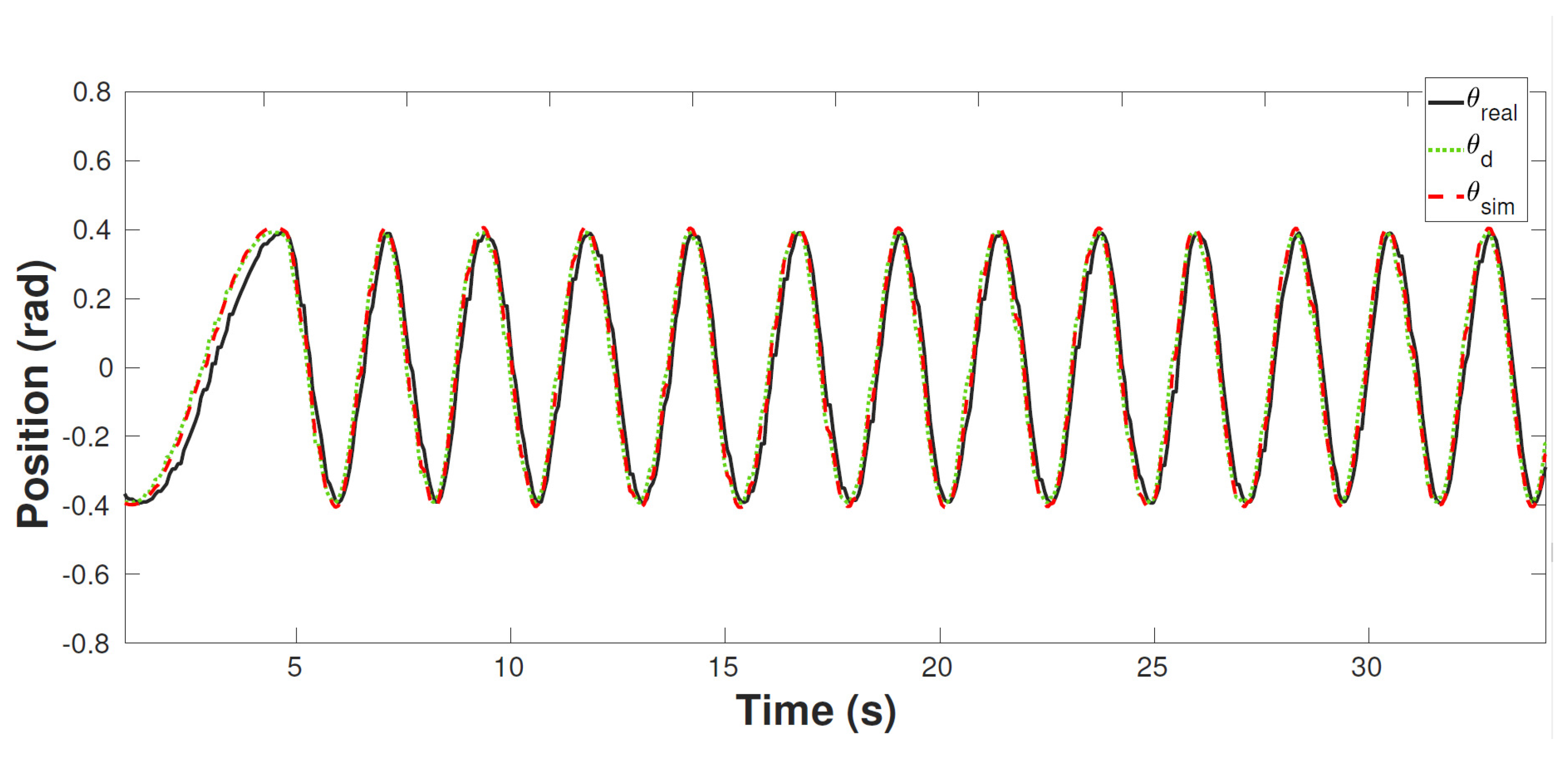
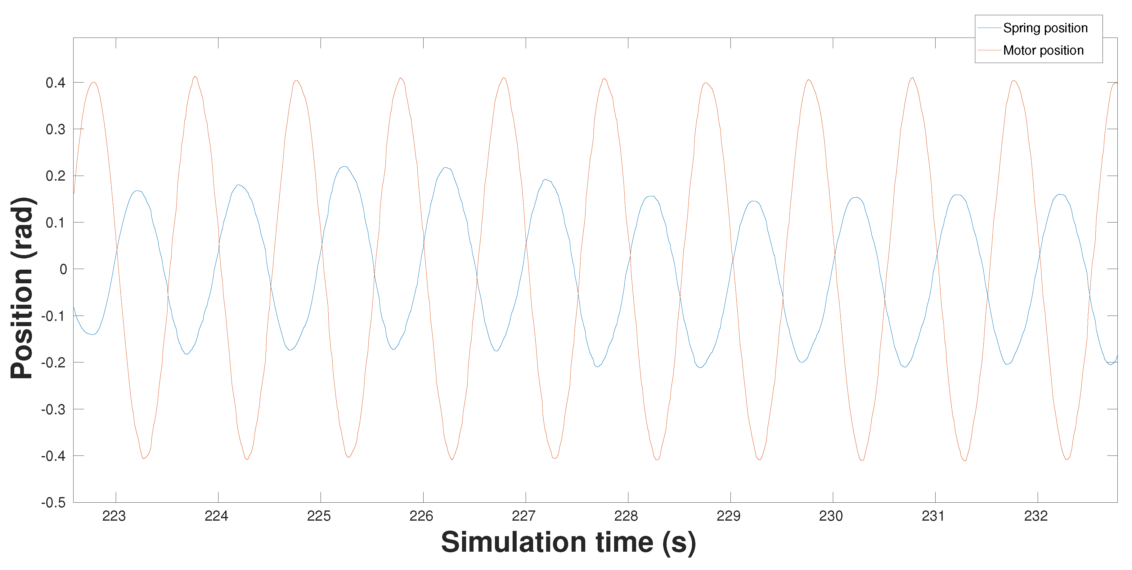
5. Simulations and Experimental Results

In this section, preliminary experimental simulations are considered with the aim of exploiting and validating the design features of Serpens. In particular, the possibility of implementing different characteristics of Serpens through the built-in capabilities of the Universal Robotic Description Format (URDF) [35] language and the Gazebo simulator is considered. In addition, the possibility of replicating the design of the physical model by separating the motor-side and spring-side dynamics in a simulated environment is studied.
To simulate the motor-side and spring-side dynamics, each joint of Serpens is modelled as a two-joint structure, as in the physical model. The generic configuration of links and joints for the simulated version of Serpens is shown in Figure 13. The motor-side dynamics are simulated with a regular revolute joint that is connected from the link to a shaft. The shaft is connected to the next link through a joint by simulating the spring dynamics. Exploiting the fact that the URDF is converted to Simulation Description Format (SDF) when imported to Gazebo, it is possible to use the SDF joint parameter springStiffness to simulate the spring dynamics. The capabilities of macros in the Extensible Markup Language (XML) Macros (Xacro) language is consistently used to provide an easily configurable setup of links and joints in the simulated environment, thus allowing the implementation of pitch–yaw, pitch–pitch and yaw–yaw configurations.
An initial experiment includes the simulated environment and one physical joint module containing the OpenCM 9.04 and the XM430W-210T servo motor. The OpenCM 9.04 micro-controller is connected to and powered by an external computer running the proposed ROS-based architecture. The communication is achieved by using the rosserial package [36]. The XM430W-210T actuator is connected through the TTL port of the micro-controller, while the power to the actuator is provided by an external 12V power-supply. The OpenCM 9.04 micro-controller runs a node with a subscriber for set-points and a publisher for the actuator feedback. The feedback is collected from the control table of the XM430W-210T [28] for each execution loop. The controller-node in the external computer intercepts the feedback through a subscriber and continuously publishes the desired position ( θ d ) governed by the following equation:
θ d = A s i n ( 2 π ( t + n ξ ) ) ,
where t is the time of the ROS-clock, n is the index of the joint to be controlled, and ξ is the spatial frequency. The results of this experiment are depicted in Figure 14, where θ d denotes the desired position of the actuator, θ r e a l is the actual position of the XM430W-210, and θ s i m is the actual position of the simulated joint in Gazebo. The findings of the experiments show a slight delay in terms of the feedback from the XM430W-210T actuator. This is to be expected, as the OpenCM 9.04 subscribes and publishes the set-point, waits for a return feedback signal from the XM430W-210T and publishes the feedback intercepted by the controller-node. To characterise the entity of this delay, time measurements were collected during the proposed experiment. In particular, the delay between the instant when data are sent from the controller-node and the time when the corresponding feedback is received was monitored over time. The results are shown in Figure 15. The maximum value is 0.0280 s, the minimum value is 0.0080 s, and the estimated average delay is 0.0152 s.
An additional simulation was performed to highlight the behaviour of the proposed SEA of Serpens. As shown in Figure 16, a scenario of a terrain cluttered with cylindrical objects is simulated. The entire body of Serpens is constrained by obstacles. The same input signal as outlined in Equation (1) for the desired position ( θ d ) is adopted to control the joint module close to the head, as highlighted in Figure 16. The oscillatory motion of the joint module determines collisions of the corresponding link with the adjacent obstacles. These collisions are accommodated through the high level of compliance offered by the SEA of Serpens. The motor position θ m is allowed movement through passive-compliance despite the load position θ l being blocked by external obstacles. The consequential deviation over time between the motor gear position and the spring reference position is shown in Figure 17.

6. Conclusions and Future Work

Serpens, a low-cost snake robot with elastic joints, torque-controlled actuators and a screw-less assembly mechanism, is presented in this paper based on a modular design and the use of the Robot Operating System (ROS) [12]. The design of the robot relies exclusively on low-cost commercial-off-the-shelf (COTS) components. Fused Deposition Modelling (FDM) manufacturing technology is adopted for 3D-printing the robot modules with polylactic acid (PLA), thus making the rapid-prototyping process very fast and economical. A screw-less assembly mechanism makes it possible to assemble the modules and reconfigure the robot in a very reliable, fast and robust manner. A low-cost sensing approach is adopted to allow for torque sensing at the joint level, sensitive collision detection and joint compliant control. These characteristics make Serpens very suitable for the interaction with unmapped and dynamic environments or for traversing terrains cluttered with obstacles. The system architecture also follows the concept of modularity on both the software and hardware sides. Each module is independent, being controlled by a self-reliant controller board. The choice of ROS for the implementation of the control framework enables researchers to develop different control algorithms for perception-driven obstacle-aided locomotion (POAL) in a simulated environment with Gazebo. This integration makes the development of control algorithms safe, rapid and efficient. Experimental and simulation results are presented to illustrate the potential of the proposed design.
As future work, the design of reliable low-level control algorithms for the proposed elastic joints will be investigated. Indeed, the design of robust and effective low-level control approaches is essential to enable the achievement of POAL for real-world applications. To achieve this, the current low-level software architecture of Serpens must be complemented with a hierarchical organisation by considering the standard functions and capabilities of guidance, navigation, and control (GNC) [37]. Regarding the mechanical design of Serpens, the possibility of testing polymers or elastomers and comparing the compliance with our current design based on the use of mechanical springs will also be considered in the future. Moreover, the possibility for Serpens to locomote in applications where the gap is narrower than the width of the robot body, i.e., within narrow vertical pipes or walls, will also be explored. More intensive heat dissipation tests are required for practical applications.

Author Contributions

Conceptualization, F.S.; Methodology, F.S.; Software, F.S. and E.H.; Validation, F.S., E.H. and S.L.A.; Formal Analysis, F.S.; Investigation, F.S., E.H., P.A.S., S.L.A.; Resources, F.S.; Data Curation, F.S., E.H., P.A.S., S.L.A.; Writing—Original Draft Preparation, F.S., E.H., P.A.S., S.L.A.; Writing—Review & Editing, F.S.; Visualization, F.S., E.H., P.A.S., S.L.A.; Supervision, F.S.; Project Administration, F.S.; Funding Acquisition, F.S.

Funding

This work was supported by the Dept. of Science and Industry systems, University of South-Eastern Norway (USN), project title “Secure Multi-sensor Autonomous RoboTs and surveillance operations for Search And Rescue (SMART-SAR) operations in smart buildings”.

Acknowledgments

The authors gratefully acknowledge the contribution of Richard Thue in the 3D-printing prototyping process of this work. The authors also thank Kiran Raja, John Mulholland, Tuan Minh Hua and Thong Ho Sy.

Conflicts of Interest

The authors declare no conflict of interest.

Abbreviations

The following abbreviations are used in this manuscript:
POALperception-driven obstacle-aided locomotion
SEAseries elastic actuator
ROSRobot Operating System
FDMFused Deposition Modelling

References

  1. Marvi, H.; Gong, C.; Gravish, N.; Astley, H.; Travers, M.; Hatton, R.L.; Mendelson, J.R.; Choset, H.; Hu, D.L.; Goldman, D.I. Sidewinding with minimal slip: Snake and robot ascent of sandy slopes. Science 2014, 346, 224–229. [Google Scholar] [CrossRef] [PubMed] [Green Version]
  2. Sanfilippo, F.; Stavdahl, Ø.; Liljebäck, P. SnakeSIM: A ROS-based rapid-prototyping framework for perception-driven obstacle-aided locomotion of snake robots. In Proceedings of the IEEE International Conference on Robotics and Biomimetics (ROBIO), Macau, China, 5–8 December 2017; pp. 1226–1231. [Google Scholar]
  3. Sanfilippo, F.; Stavdahl, Ø.; Liljebäck, P. SnakeSIM: A ROS-based control and simulation framework for perception-driven obstacle-aided locomotion of snake robots. Artif. Life Robot. 2018, 23, 449–458. [Google Scholar] [CrossRef]
  4. Sanfilippo, F.; Azpiazu, J.; Marafioti, G.; Transeth, A.A.; Stavdahl, Ø.; Liljebäck, P. A review on perception-driven obstacle-aided locomotion for snake robots. In Proceedings of the 14th International Conference on Control, Automation, Robotics and Vision (ICARCV), Phuket, Thailand, 13–15 November 2016; pp. 1–7. [Google Scholar]
  5. Sanfilippo, F.; Azpiazu, J.; Marafioti, G.; Transeth, A.A.; Stavdahl, Ø.; Liljebäck, P. Perception-driven obstacle-aided locomotion for snake robots: The state of the art, challenges and possibilities. Appl. Sci. 2017, 7, 336. [Google Scholar] [CrossRef]
  6. Sanfilippo, F.; Stavdahl, Ø.; Marafioti, G.; Transeth, A.A.; Liljebäck, P. Virtual functional segmentation of snake robots for perception-driven obstacle-aided locomotion. In Proceedings of the IEEE International Conference on Robotics and Biomimetics (ROBIO), Qingdao, China, 3–7 December 2016; pp. 1845–1851. [Google Scholar]
  7. Eitel, E. The Rise of Soft Robots and the Actuators That Drive Them. Available online: https://www.machinedesign.com/robotics/rise-soft-robots-and-actuators-drive-them (accessed on 15 November 2018).
  8. Haddadin, S.; Mansfeld, N.; Albu-Schäffer, A. Rigid vs. elastic actuation: Requirements & performance. In Proceedings of the IEEE/RSJ International Conference on Intelligent Robots and Systems (IROS), Algarve, Portugal, 7–12 October 2012; pp. 5097–5104. [Google Scholar]
  9. Rollinson, D.; Bilgen, Y.; Brown, B.; Enner, F.; Ford, S.; Layton, C.; Rembisz, J.; Schwerin, M.; Willig, A.; Velagapudi, P.; et al. Design and architecture of a series elastic snake robot. In Proceedings of the IEEE/RSJ International Conference on Intelligent Robots and Systems (IROS 2014), Chicago, IL, USA, 14–18 September 2014; pp. 4630–4636. [Google Scholar]
  10. Rollinson, D.; Ford, S.; Brown, B.; Choset, H. Design and modeling of a series elastic element for snake robots. In Proceedings of the ASME 2013 Dynamic Systems and Control Conference. American Society of Mechanical Engineers, Palo Alto, CA, USA, 21–23 October 2013; p. V001T08A002. [Google Scholar]
  11. Lipson, H.; Kurman, M. Fabricated: The New World of 3D Printing; John Wiley & Sons: New York, NY, USA, 2013. [Google Scholar]
  12. Quigley, M.; Conley, K.; Gerkey, B.; Faust, J.; Foote, T.; Leibs, J.; Wheeler, R.; Ng, A.Y. ROS: An open-source Robot Operating System. In Proceedings of the IEEE International Conference on Robotics and Automation (ICRA), Kobe, Japan, 12–17 May 2009; Volume 3, p. 5. [Google Scholar]
  13. Liljeback, P.; Pettersen, K.Y.; Stavdahl, Ø.; Gravdahl, J.T. Snake robot locomotion in environments with obstacles. IEEE/ASME Trans. Mech. 2012, 17, 1158–1169. [Google Scholar] [CrossRef]
  14. Hirose, S. Biologically Inspired Robots: Snake-Like Locomotors and Manipulators; Oxford University Press: Oxford, UK, 1993. [Google Scholar]
  15. Bayraktaroglu, Z.Y. Snake-like locomotion: Experimentations with a biologically inspired wheel-less snake robot. Mech. Mach. Theory 2009, 44, 591–602. [Google Scholar] [CrossRef]
  16. Takaoka, S.; Yamada, H.; Hirose, S. Snake-like active wheel robot ACM-R4. 1 with joint torque sensor and limiter. In Proceedings of the IEEE/RSJ International Conference on Intelligent Robots and Systems (IROS), San Francisco, CA, USA, 25–30 September 2011; pp. 1081–1086. [Google Scholar]
  17. Liljebäck, P.; Stavdahl, Ø.; Pettersen, K.Y.; Gravdahl, J.T. A modular and waterproof snake robot joint mechanism with a novel force/torque sensor. In Proceedings of the 2012 IEEE/RSJ International Conference on Intelligent Robots and Systems (IROS), Algarve, Portugal, 7–12 October 2012; pp. 4898–4905. [Google Scholar]
  18. Liljebäck, P.; Stavdahl, Ø.; Pettersen, K.Y.; Gravdahl, J.T. Mamba-A waterproof snake robot with tactile sensing. In Proceedings of the IEEE/RSJ International Conference on Intelligent Robots and Systems (IROS 2014), Chicago, IL, USA, 14–18 September 2014; pp. 294–301. [Google Scholar]
  19. Pratt, G.A.; Williamson, M.M. Series elastic actuators. In Proceedings of the IEEE/RSJ International Conference on Intelligent Robots and Systems, Pittsburgh, PA, USA, 5–9 August 1995; Volume 1, pp. 399–406. [Google Scholar]
  20. Robinson, D.W.; Pratt, J.E.; Paluska, D.J.; Pratt, G.A. Series elastic actuator development for a biomimetic walking robot. In Proceedings of the IEEE/ASME International Conference on Advanced Intelligent Mechatronics, Atlanta, GA, USA, 19–23 September 1999; pp. 561–568. [Google Scholar]
  21. Rouse, E.J.; Mooney, L.M.; Martinez-Villalpando, E.C.; Herr, H.M. Clutchable series-elastic actuator: Design of a robotic knee prosthesis for minimum energy consumption. In Proceedings of the International Conference on Rehabilitation Robotics (ICORR 2013), Bellevue, WA, USA, 20–24 June 2013. [Google Scholar]
  22. Paine, N.; Mehling, J.S.; Holley, J.; Radford, N.A.; Johnson, G.; Fok, C.L.; Sentis, L. Actuator control for the NASA-JSC Valkyrie humanoid robot: A decoupled dynamics approach for torque control of series elastic robots. J. Field Robot. 2015, 32, 378–396. [Google Scholar] [CrossRef]
  23. Nguyen, M.N.; Tran, D.T.; Ahn, K.K. Robust position and vibration control of an electrohydraulic series elastic manipulator against disturbance generated by a variable stiffness actuator. Mechatronics 2018, 52, 22–35. [Google Scholar] [CrossRef]
  24. Rollinson, D.; Alwala, K.V.; Zevallos, N.; Choset, H. Torque control strategies for snake robots. In Proceedings of the IEEE/RSJ International Conference on Intelligent Robots and Systems (IROS 2014), Chicago, IL, USA, 14–18 September 2014; pp. 1093–1099. [Google Scholar]
  25. Intel. Intel RealSense D435. Available online: https://click.intel.com/intelr-realsensetm-depth-camera-d435.html (accessed on 15 November 2018).
  26. Gonzalez-Gomez, J.; Zhang, H.; Boemo, E. Locomotion principles of 1D topology pitch and pitch-yaw-connecting modular robots. In Bioinspiration and Robotics Walking and Climbing Robots; InTech: Vienna, Austria, 2007. [Google Scholar]
  27. Robinson, D.W. Design and Analysis of Series Elasticity in Closed-Loop Actuator Force Control. Ph.D. Thesis, Massachusetts Institute of Technology, Cambridge, MA, USA, 2000. [Google Scholar]
  28. DYNAMIXEL. XM430-W210T. Available online: http://support.robotis.com/en/product/actuator/dynamixel_x/xm_series/xm430-w210.htm (accessed on 15 November 2018).
  29. Tsardoulias, E.; Mitkas, P. Robotic frameworks, architectures and middleware comparison. arXiv, 2017; arXiv:1711.06842. [Google Scholar]
  30. Koenig, N.; Howard, A. Design and use paradigms for gazebo, an open-source multi-robot simulator. In Proceedings of the IEEE/RSJ International Conference on Intelligent Robots and Systems (IROS), Sendai, Japan, 28 September–2 October 2004; Volume 3, pp. 2149–2154. [Google Scholar]
  31. Kam, H.R.; Lee, S.H.; Park, T.; Kim, C.H. RViz: A toolkit for real domain data visualization. Telecommun. Syst. 2015, 60, 337–345. [Google Scholar] [CrossRef]
  32. Arduino. Arduino, an Open-Source Electronics Prototyping Platform. Available online: http://arduino.cc/ (accessed on 15 November 2018).
  33. RoLin. RoLin Rotary Incremental Encoder. Available online: https://www.rls.si/en/products/rotary-magnetic-encoders/rolin-rotary-incremental-magnetic-encoder-system (accessed on 15 November 2018).
  34. Robot Operating System (ROS). realsense2_camera. Available online: http://wiki.ros.org/realsense2_camera (accessed on 15 November 2018).
  35. Open Source Robotics Foundation. Tutorial: Using a URDF in Gazebo. Available online: http://gazebosim.org/tutorials/?tut=ros_urdf (accessed on 15 November 2018).
  36. Robot Operating System (ROS). Rosserial. Available online: http://wiki.ros.org/rosserial (accessed on 15 November 2018).
  37. Kendoul, F. Towards a unified framework for uas autonomy and technology readiness assessment (atra). In Autonomous Control Systems and Vehicles; Springer: Berlin, Germany, 2013; pp. 55–71. [Google Scholar]
Figure 1. Serpens: A low-cost ROS-based snake robot with series elastic actuator (SEA), precision torque control and a screw-less assembly mechanism.
Applsci 09 00396 g001
Figure 2. The head, joint, and tail modules of Serpens: (a) the head module of Serpens with the Intel RealSense D435 stereoscopic camera; (b) one of the joint modules of Serpens; and (c) the tail module of Serpens.
Applsci 09 00396 g002
Figure 3. Two different connections can be achieved with Serpens: (a) pitch connection; (b) yaw connection; and (c) pitch–yaw connection.
Applsci 09 00396 g003
Figure 4. An exploded view of a joint module: (1) screw-less assembly mechanism; (2) micro-controller; (3) actuator; (4) elastic gear; (5) rotary encoder; (6) bearing; and (7) battery-pack.
Applsci 09 00396 g004
Figure 5. The proposed screw-less assembly mechanism consists of three 3D-printed components (two enclosure parts and a push-button) with two springs orientated in the direction of the pin placed under the enclosure cover.
Applsci 09 00396 g005
Figure 6. The proposed design of the elastic gears for Serpens. The figure shows: the housing (left); the base (middle); and the cogwheel (right). The shaft (not depicted in this figure) runs through all parts. Compression springs are placed in the chamber of the cogwheel on each side of the outset of the base, providing passive-compliance.
Applsci 09 00396 g006
Figure 7. The heat transfer performance of the selected actuator is qualitatively shown using a heat map. The motor was run for 50 min at a constant velocity of approximately 57.25 RPM. The servo was run without load continuously in one direction and monitored at 0 min, 25 min and 50 min, respectively.
Applsci 09 00396 g007
Figure 8. The interface between the head module and each generic joint module.
Applsci 09 00396 g008
Figure 9. The simulated joint module showing the divergence of the actuator position θ m , and load position θ l as a result of the elasticity in the joint when external forces ( F e x t ) are applied to the load.
Applsci 09 00396 g009
Figure 10. The simulated Gazebo environment showing Serpens in a pitch–yaw configuration, and the output of the simulated RGB (top) and RGBD (bottom) channels from the stereoscopic camera visualised through RVIZ.
Applsci 09 00396 g010
Figure 11. Node-graph showing the structure of nodes and topics contributing to the control to both the simulated and physical robot.
Applsci 09 00396 g011
Figure 12. The proposed control framework for achieving POAL.
Applsci 09 00396 g012
Figure 13. The generic configuration of links and joints in Xacro/URDF. Joints are shown as ellipses, while links are depicted as boxes.
Applsci 09 00396 g013
Figure 14. Matlab-plot showing the setpoint θ d , the joint position feedback from simulation θ s i m , and the feedback from a XM430W-210T actuator θ r e a l .
Applsci 09 00396 g014
Figure 15. Time plot showing the delay between the instant when data is sent from the controller-node and the time when the corresponding feedback is received. The maximum value is 0.0210 s, the minimum value is 0.0100 s, and the estimated average delay is 0.0129 s.
Applsci 09 00396 g015
Figure 16. The body of Serpens is constrained by cylindrical obstacles. (a) The same input signal as outlined in Equation (1) for the desired position ( θ d ) is adopted to control the highlighted joint module close to the head. (b) A zoomed view of one of the joint modules while colliding with obstacles. The motor position θ m is allowed movement through passive-compliance despite of the load position θ l being blocked by external obstacles.
Applsci 09 00396 g016
Figure 17. The deviation over time between the motor gear position and the spring reference position.
Applsci 09 00396 g017
Table 1. Parameters of Serpens’s joint module.
ParameterValue
Weight∼500 g
Width/height75 mm
Length between joint axes200 mm
Degrees of freedom1
Max joint travel ± 90
Max continuous joint torque3.0 Nm (at 12 V)
Max joint speed with no load77 RPM (at 12 V)
Operating Temperature (actuators)−5 °C∼80 °C

