Review

Fixed Grid Numerical Models for Solidification and Melting of Phase Change Materials (PCMs)

by
José Henrique Nazzi Ehms
1,
Rejane De Césaro Oliveski
1,
Luiz Alberto Oliveira Rocha
1,
Cesare Biserni
2,* and
Massimo Garai
2
1
Mechanical Engineering Graduate Program, Universidade do Vale do Rio dos Sinos, São Leopoldo 93022-750, Brazil
2
Department of Industrial Engineering (DIN), School of Engineering and Architecture, Alma Mater Studiorum, University of Bologna, Viale Risorgimento 2, 40136 Bologna, Italy
*
Author to whom correspondence should be addressed.
Appl. Sci. 2019, 9(20), 4334; https://doi.org/10.3390/app9204334
Submission received: 2 September 2019 / Revised: 2 October 2019 / Accepted: 8 October 2019 / Published: 15 October 2019
(This article belongs to the Section Materials Science and Engineering)

Abstract

:
Phase change materials (PCMs) are classified according to their phase change process, temperature, and composition. The utilization of PCMs lies mainly in the field of solar energy and building applications as well as in industrial processes. The main advantage of such materials is the use of latent heat, which allows the storage of a large amount of thermal energy with small temperature variation, improving the energy efficiency of the system. The study of PCMs using computational fluid dynamics (CFD) is widespread and has been documented in several papers, following the tendency that CFD nowadays tends to become increasingly widespread. Numerical studies of solidification and melting processes use a combination of formulations to describe the physical phenomena related to such processes, these being mainly the latent heat and the velocity transition between the liquid and the solid phases. The methods used to describe the latent heat are divided into three main groups: source term methods (E-STM), enthalpy methods (E-EM), and temperature-transforming models (E-TTM). The description of the velocity transition is, in turn, divided into three main groups: switch-off methods (SOM), source term methods (STM), and variable viscosity methods (VVM). Since a full numerical model uses a combination of at least one of the methods for each phenomenon, several combinations are possible. The main objective of the present paper was to review the numerical approaches used to describe solidification and melting processes in fixed grid models. In the first part of the present review, we focus on the PCM classification and applications, as well as analyze the main features of solidification and melting processes in different container shapes and boundary conditions. Regarding numerical models adopted in phase-change processes, the review is focused on the fixed grid methods used to describe both latent heat and velocity transition between the phases. Additionally, we discuss the most common simplifications and boundary conditions used when studying solidification and melting processes, as well as the impact of such simplifications on computational cost. Afterwards, we compare the combinations of formulations used in numerical studies of solidification and melting processes, concluding that “enthalpy–porosity” is the most widespread numerical model used in PCM studies. Moreover, several combinations of formulations are barely explored. Regarding the simulation performance, we also show a new basic method that can be employed to evaluate the computing performance in transient numerical simulations.

Graphical Abstract

1. Introduction

Thermal energy storage systems can employ sensible or latent heat. Sensible heat storage technology is more widespread than latent heat storage; however, the use of latent heat storage presents the main advantage of a higher energy storage density [1]. Latent heat thermal energy storage with phase change materials (PCMs) has been extensively studied due to its potential in peak absorption both in energy demand and in energy supply [2]. The study of PCMs was popular during the energy crisis in the 1970s and 1980s, with the primary aim to use PCMs in solar thermal energy storage [3]. As a transient process, the time elapsed by the complete phase change of the PCM (charge or discharge) is essential to defining the viability of the latent heat thermal energy storage system (LHTESS). This period covered by charge or discharge can vary from low peak attenuation to daily base or long-term yearly base [4]. Therefore, the use of PCMs includes a wide range of applications, such as building passive climate control [5,6,7], concentrating solar power stations [8,9,10], electronic device thermal protection [11], textile products [12], and waste heat recovery [13,14].
Several authors have reviewed PCMs with regard to their applications, materials, numerical models, and container shape. Thus, some significant parameters have been established [15] for the application and study of PCMs, such as desirable characteristics of materials, requirements of the LHTESS, initial classification of PCMs and latent heat measurement techniques. Additional contributions have been performed by Zalba et al. [16], Farid et al. [1], Sharma et al. [2], and Agyenim et al. [3]. More specifically, works [17,18] are focused on PCMs for high-temperature applications, while Ge et al. [19] have reviewed the group of metallic PCMs. Salunkhe and Shembekar [20] have outlined the heat transfer characteristics for different size scales of encapsulation, as well as the effects of the PCM container material in the phase change process. Dhaidan and Khodadadi [21] focused their study on the melting process of PCMs and the effects of container shape on heat transfer and the melting process. Fan and Khodadadi [22] and Khan et al. [23] have analyzed the techniques adopted for thermal conductivity enhancement of thermal energy storage using PCMs. Verma et al. [24] have recounted thermal energy storage systems with PCMs: the models were separated according to the first and second laws of thermodynamics. Regarding the numerical approach, Zalba et al. [16] and Sharma et al. [2] have outlined some characteristics of the formulations used to describe phase-change processes. Dutil et al. [25] and Al-Abidi et al. [26] have reviewed several numerical studies of PCMs and have presented the characteristics of computational models according to the geometry of the PCM container. Liu et al. [27] have analyzed the heat transfer mechanisms of phase change as well as analytical and numerical models for phase change. They reviewed PCMs consistently with the division into two categories: considering only heat conduction or considering conduction and convection simultaneously. Ziskind [28] has pointed out physical phenomena associated with PCMs and has reviewed numerical methods used for modeling such phenomena. Some authors have presented specific reviews for numerical models, such as Voller et al. [29] and Samarskii et al. [30], in which phase change formulations and numerical procedures were pointed out. Hu and Argyropoulos [31] focused their study mainly on latent heat formulation. Ma and Zhang [32] have reviewed numerical models for the velocity transition between solid and liquid and performed tests and comparisons between different models.
Despite the large number of review papers regarding PCMs, very few are specifically about numerical modeling features. Among these reviews, the most common approach is to focus on latent heat modeling or velocity transition modeling. In the present paper, we review the formulations used to describe both physical phenomena and relate to the features that occur in solidification and melting processes. Thus, the present review has been divided into four main parts: (1) review of PCM classification and application; (2) analysis of the main features of phase change processes regarding cavity format and thermal conditions; (3) review of fixed grid numerical models used for phase-change processes; (4) review of simplifications and other conditions commonly used in numerical studies of PCMs, performance evolution in computers used for numerical simulations, and compilation of the combinations of phase change numerical models most common in the literature.

2. PCMs: Basic Characterization

Latent heat is present in every form of phase change: solid–solid, solid–liquid (solidification and melting), liquid–gas (boiling and condensation) or solid–gas (sublimation). In comparison with sensible heat, a large amount of energy is stored in phase changes, with small temperature variation. Phase change processes that involve a gas phase, such as boiling, condensation, and sublimation processes, are characterized by a considerable variation in the material volume [2,19]. Thus, these processes need pressure vessels, which make the thermal energy storage system more complex and less feasible [15]. The transition between two solid phases or between solid and liquid implies less volume variation [1] so that the increase in pressure is also moderate; therefore, solid–solid and solid–liquid phase changes of PCMs make the energy storage system less complex. Furthermore, PCMs with solid–solid transitions present as their main advantage the possibility of direct contact of the heat transfer fluid (HTF) with the PCM, as the shape of the solid remains during the phase change [33,34]. However, it is worth mentioning that fewer materials present a solid–solid transition, having commonly lower latent heat than that corresponding to the solid–liquid transition [13,18].

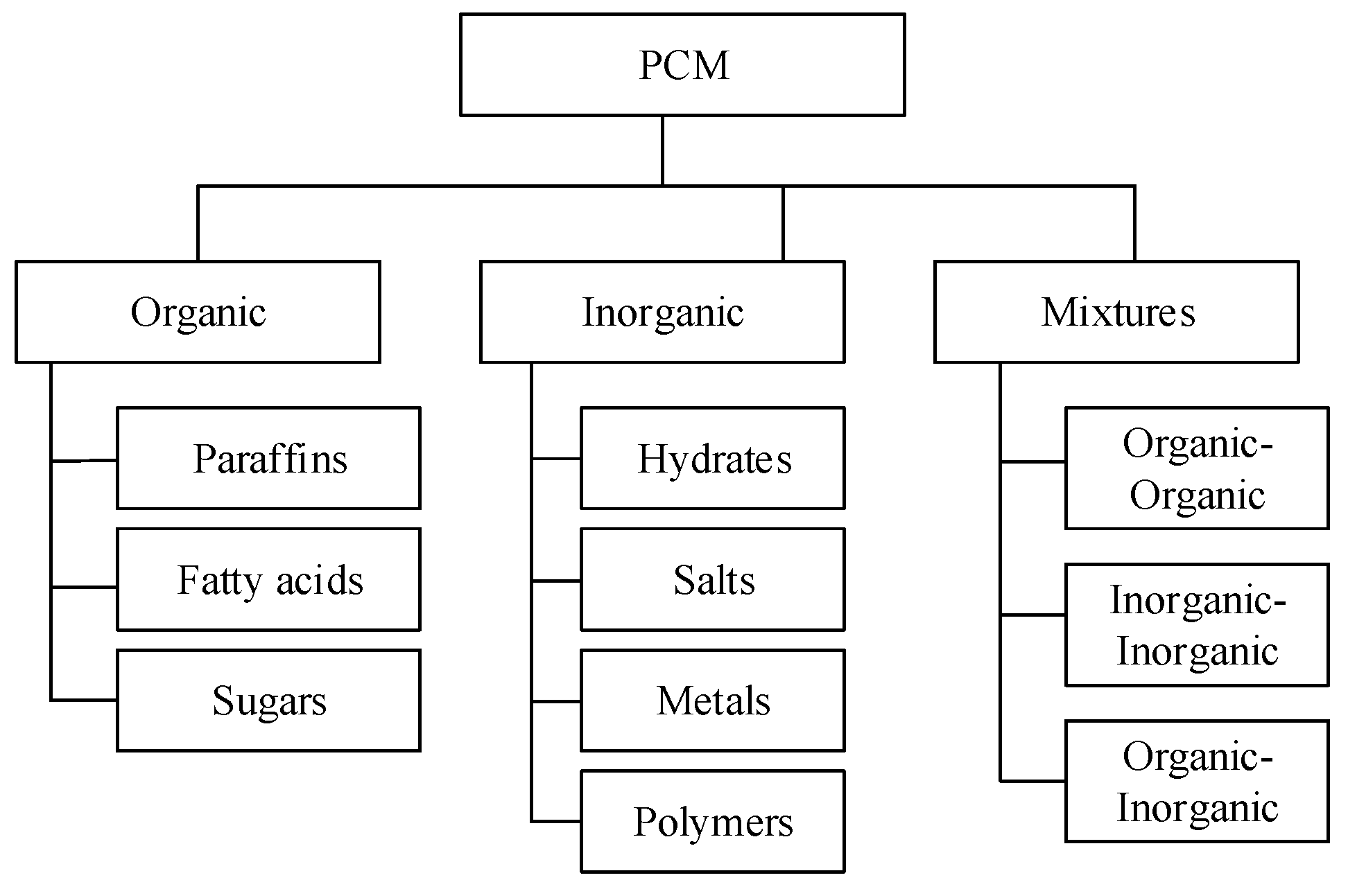
2.1. PCMs Classification

PCMs are classified according to composition, phase change process, and phase change temperature. More precisely, the latter turns out to be the main parameter for the choice of a PCM, which needs to be suitable for the temperature range that occurs in the considered application. In general, the classification according to the phase change process is divided into four subcategories: solid–solid, solid–liquid, liquid–gas, and solid–gas [19]. As for the classification concerning phase change temperature, three groups are universally accepted among the authors (low, medium, and high temperature), even if there is no clear definition of the temperature ranges for each group, as shown in Table 1.
Therefore, the classification of PCMs according to composition is still the most common in the literature due to its intrinsic simplicity, since groups of materials with a similar composition also have similar characteristics. Several authors have presented such a classification, based on three main groups: organic, inorganic, and mixtures. Each main group has subgroups, as highlighted in Figure 1, according to the classifications shown in works [2,15,16,18,19].

2.2. PCM Applications

The use of PCMs covers several applications, with a higher amount of studies focused on solar energy and Heating, Ventilation and Air Conditioning (HVAC) Systems [16]. In addition, many other areas can benefit from using PCM systems, including the construction field, space crafts and satellites, waste heat recovery, photovoltaic–thermal solar collectors, electronic equipment, personal comfort, and medical systems, among others. Thermal energy storage always plays an essential role in concentrating solar power plants, as it increases the availability of the plant to periods without sunlight. In such systems, part of the solar energy collected during the day is redirected to a reservoir with PCM that keeps the electricity generated during the night [8]. An improvement in the performance of the thermal energy storage and power plant is the use of a cascaded storage system [9,10]. Cascaded PCM systems are composed of several PCMs with different phase change temperatures and are configured with the phase change temperature in ascending order. Thus, the direction of the HTF flow is reversed between charge and discharge. In photovoltaic solar collectors, the usage of PCMs results in a reduction in the peak temperature. Thus, the losses due to overheating are reduced in the collector [14]. Another important application of PCMs is in photovoltaic–thermal solar collectors, where PCMs have been observed to improve the overall efficiency of the collector [12,35,36]. The same occurs in the utilization of PCMs in solar distillation processes in which the operational period after sunset is extended. As a result, both efficiency and productivity are increased [37,38]. Another essential building application of PCMs is the thermal storage in solar heating systems for domestic water, as pointed out in works [15]. Commonly, such systems use water as sensible heat storage due to the low cost of installation. The use of PCMs as latent heat storage in solar heating systems entails the main advantages of the reduction in reservoir size and improvement of the overall system efficiency [39]. However, the cost of the PCM may represent an obstacle to large-scale employment in domestic hot water systems [16]. In air HVAC systems, for example, the utilization of PCMs with phase change temperature lower than ambient temperature can bring about several advantages in order to reduce the peak energy load and slightly increase the efficiency of the equipment [40]. In the construction field, PCMs are used for passive storage daily, in the form of microcapsules contained in thermal insulation boards. The use of these boards provides temperature peak attenuation inside the building, lowering the maximum temperature during the day and increasing the minimum temperature during the night. Therefore, the thermal load is reduced, and consequently, the load of heating or air conditioning is also reduced [2]. Space crafts and satellites orbiting the Earth operate in a cyclical thermal condition that varies between extremes. When the spacecraft is exposed to the sun, the temperature reaches its maximum. Oppositely, when the spacecraft is in the shadow of the Earth, the temperature reaches its minimum. Thus, the use of PCM attenuates the high- and low-temperature peaks and represents great potential to reduce energy consumption [41]. Even waste heat recovery in industries using PCMs represents excellent potential for energy saving [18]. A representative example is the steelmaking industry, in which vast amounts of heat are rejected to cool the alloys produced [42]. According to Yagi and Akiyama [43], after having been stored in the PCM, the waste heat can be directed to a supply center for public use. In vehicles with internal combustion engines and hydraulic machines, waste heat can be directly stored in the PCM and used to preheat the engine, as a cold start represents higher fuel consumption and more significant wear of the moving parts [16]. The use of PCMs is attractive in the automotive industry for battery thermal management, mainly in hybrid and electric vehicles. High and low temperature can influence the battery performance and in more critical cases, overheating of the battery can damage or even cause failure in such a component, causing safety risks [44]. The prevention of battery failures due to overheating is also crucial in electronic equipment. In this context, work [11] has outlined the application of PCMs in such equipment in order to increase the heat dissipation capability. Textile applications of encapsulated PCMs include clothing for thermal comfort in hot and cold environments, space suits, sportswear, medical applications, shoes, and accessories [45]. Heat storage with PCMs also represents an attractive option in solar dryers for agricultural and food products [46]. Additional examples of PCMs applications are in medicine, including hot-cold therapies, food conservation, and transportation [16].

3. Phase Change Processes

Phase change processes can occur under a single temperature (isothermal phase change) or within a temperature interval, also known as continuous properties phase change [47]. In the latter case, the properties vary continuously within the interval, known as the mushy zone. Figure 2 illustrates the enthalpy variation with temperature for isothermal phase change (dashed line) and continuous properties phase change (solid line).
The phase change temperature is Tm for the isothermal phase change, while the mushy zone in the continuous properties phase change is limited by solidus temperature (Ts) in the lower bound and by liquid temperature (Tl) in the upper bound. Thus, solid and liquid phases coexist in the mushy zone, whose thickness is commonly proportional to the temperature interval, being therefore greater than zero. The temperature interval in continuous properties phase change is commonly approximated to an equivalent Tm to simplify and include parameters in the analysis, as well as apply boundary conditions, perform calculations, and obtain results. The most common and simplest approximation used in works [48,49] is given by:
T m = T S + T L 2
Examples of materials with isothermal phase change are pure substances and eutectic mixtures, as highlighted in work [50]. Continuous properties phase change exists in metallic alloys, mixtures, and amorphous substances, as illustrated in works [47,51].

3.1. Solidification Process

In the solidification process, heat transfer is predominantly conductive [52]. However, the effects of convection can be observed in the case of rectangular cavities with heat transfer on one side [53]. In such domains, convection heat transfer affects the shape of the solid along the process. The main characteristic detected in the solidification process is the formation of a solid layer, whose thickness increases gradually from the heat transfer surface [49,54]. The solidification rate is reduced throughout the process, with its effect observed through the smaller variation of the liquid fraction in the final stages. The reduction in the solidification rate is shown in detail on the experimental results obtained by Viskanta and Gau [55] for the solidification of water inside a horizontal cylinder.
The solid fraction is depicted in a dark color and the liquid fraction in a light color, as the darker portions in the center of the images are the thermocouple and overflow tube. The time interval elapsed between images (b) and (c) is higher than between images (a) and (b), even if the corresponding amount of solidified material has an inverse proportion. Also, it is possible to observe in the images a symmetric solidification pattern from the colder surface towards the center. It is worth mentioning that the main effects, as a reduction in solidification rate and symmetrical pattern from the cold surface, are linked to the different configurations. Thus, regarding geometry, these effects are observed in vertical cylinders [56], horizontal concentric cylinders with different fin configurations [57,58] and spheres [52,59].

3.2. Melting Process

In the melting process, heat conduction is dominant only in the initial stages [58]. In any case, convective heat transfer influences most of the melting process [60], as can be detected in the morphology of the solid phase. Regarding rectangular cavities with heat transfer in one side, the liquid phase close to the hot wall flows upwards due to buoyancy forces induced by density reduction in the function of temperature increase. The convective motions heated by the hot wall cause a higher melting rate in the upper region, as the solid assumes a tapered shape that becomes more evident over time, as shown in Figure 3 about experimental results outlined in work [61].
Regarding the shape of the solid phase, vertical cylinders with an adiabatic base and heat transfer on the cylindrical wall present results similar to rectangular cavities with heat transfer on one side. Vertical cylinders have symmetry around the vertical axis, which induces the solid phase to assume a conical shape, as shown in Figure 4, concerning experimental results obtained by Katsman et al. [62].
Besides the shape of a solid PCM, the adiabatic bottom surface is an additional standard feature regarding PCMs melting in rectangular cavities and vertical cylinders with a one side heated surface. The absence of heat transfer through the bottom surface maintains the position of the remaining solid phase throughout the process. However, most PCM containers present heat transfer through the bottom surface, which is more evident in horizontal cylinders and spheres but can occur as well in rectangular cavities and vertical cylinders. As different densities characterize solid and liquid PCMs, the portions with lower density tend to flow upwards. The density of the PCM is higher for the solid than for the liquid. Thus, in melting processes with heat transfer through the lower surface, the liquid portion flows upwards and the solid is located close to the heated lower surface. For materials with higher density in the liquid phase, such as water, the opposite occurs. Melting processes in which the solid material moves towards the heated surface or vice-versa are known as “close contact melting” [63] or “unconstrained melting” [58]. The main characteristic of this process is the formation of a thin liquid layer between the solid and the heated surface. As more material melts, the liquid portion formed in this layer flows continuously towards the side edge of the solid portion, out of the region between the solid and the heated surface [64]. An example of close contact melting in a rectangular cavity is shown in Figure 5, adapted from work [65].
The shape of the solid (bright color) remains similar to the cavity shape. In comparison with the case of the rectangular cavity highlighted in Figure 3, the influence of the thermal configuration in the shape of the solid portion proves to be evident, even with the different aspect ratios of the cavities. The differences in the phase morphology when comparing close contact melting and fixed solid melting are also observable in horizontal cylinders as well as in spheres. However, other results, such as melting rate, heat flux, or total melting time, are different due to geometric characteristics. When the solid is fixed, the melting process starts symmetrically. However, over time, a wavy profile is formed in the lower region of the solid, due to convective motions of the liquid at the bottom of the cavity [58]. On the other hand, close contact melting presents shapes that are more symmetrical in the solid. Figure 6 shows the shapes of the solid PCM in the melting process in the horizontal cylinder analyzed by Sparrow and Geiger [66].
Regarding the case with the fixed solid, the wavy profile in the lower portion of the solid is visible both longitudinally (Figure 6a) and transversally (Figure 6b). The case of close contact melting (Figure 6c) does not show the wavy profile, but the solid keeps the shape more symmetrical and similar to the cavity shape. The melting process in spherical containers presents solid shapes like the transversal view of the horizontal cylinder, as depicted in Figure 7, deducted from work [58].
Based on pure observation, both close contact melting (Figure 7a) and fixed solid melting (Figure 7b) show similar solid shapes of the transversal view detected in the case of a horizontal cylinder (Figure 6c,b, respectively). Another common characteristic of close contact melting is the higher melting rate for the same geometry and same thermal condition when compared with unconstrained melting. During the close contact melting process, the solid keeps moving towards the heated surface while the liquid layer thickness is stable. This condition provides a nearly constant liquid flow upwards and consequently a nearly constant melting rate, as outlined in work [63]. The liquid layer thickness increases due to the reduction of the body forces from the solid portion, as the solid mass reduces over time [65] at the end of the process. Visualization of the liquid layer below the solid is very difficult to be observed, due to its very small thickness [63,64]. Most of the PCM melted in the entire close contact melting process comes from this liquid layer between the solid and the lower surface. However, some authors have detected a contribution of about 10–15% from natural convection in the upper region for both spheres [64] and horizontal cylinders [67]. Figure 8 shows, schematically, the liquid flow during the close contact melting inside a sphere, where it is possible to observe the liquid streams of natural convection in the upper region and the liquid layer between the solid and the lower heated surface.
The liquid amount in the layer below the solid increases from the symmetry axis as the entire surface is heated. This increase causes the variation in the velocity profile of the liquid layer towards the upper region, which is accompanied by an augmentation of the layer thickness [68]. For a given position, the velocity profile does not vary significantly [69] until the upper region of the solid reaches that position. Several studies are based on equations and correlations to describe parameters in the close contact melting such as liquid layer thickness [68,69], melting rate in the liquid layer [70,71], and the solid portion sinking [63,72]. However, until now, no direct experimental measurements of the liquid layer thickness or velocity profile have been found in the literature, due to its small thickness, which turns out to be very challenging to observe directly. Regarding numerical investigations on this topic, some authors have studied the liquid layer thickness [73,74] and the downward velocity of the solid [75,76]. Despite the actual numerical results, more effort is necessary to provide more significant results for different geometries and concerning the heat transfer and the flow inside the liquid layer.

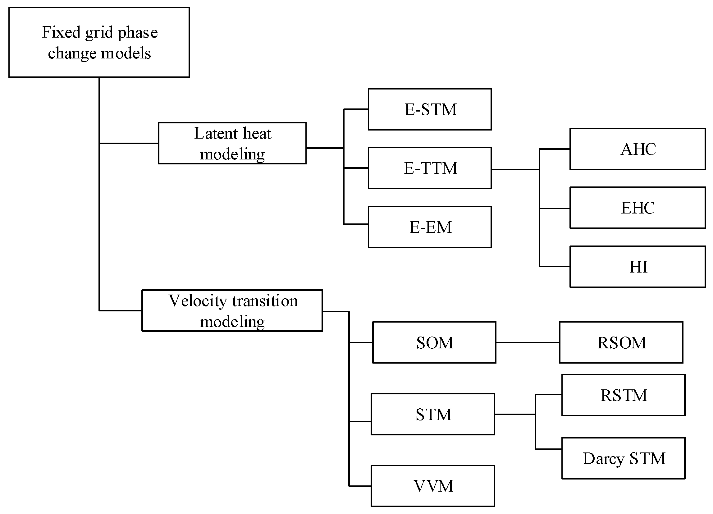
4. Numerical Models for Phase Change Processes

Isothermal phase change problems are also known as moving boundary problems or Stefan problems, due to the study of Stefan [77] of the ice cap formation in the North Pole region. The model was elaborated considering the interface between solid and liquid as a moving boundary with temperature conditions (T = Tm). The solution consisted of solving the interface position over time. Such a model presented a solution about some specific cases, i.e., considering several simplifications in the properties of the material, boundary, and initial conditions, as pointed out in work [31]. It is worth mentioning that the temperature condition in the solid–liquid interface corresponds to an isothermal phase change process, with a sharp interface. However, when referring to phase changes with continuous properties, both solid and liquid coexist in the mushy zone, and the interface is not a well-defined boundary [78]. Therefore, numerical models are most suitable for continuous properties phase change as the mushy zone represents a steep gradient in the domain. On the other hand, for isothermal phase change, the discontinuity represented by phase change is the main difficulty in managing with numerical models [47]. Numerical phase change models found in the literature are commonly divided into two main groups: fixed grid or continuum models, and variable grid or two-phase models [31]. Variable grid models are based on the implementation of separate computational domains for solid and liquid, i.e., separate equation sets, which are coupled using transference terms between the phases [79]. Thus, such models are more suitable to isothermal phase change processes, as they make possible the definition of an interface whose thickness tends to zero [78]. Besides the higher amount of equations, these procedures need interface tracking methods and grid adjustment methods according to the interface position, consequently presenting more difficulties to solving the problem. The grid position adjustment following the interface can be made through the movement of the grid points (dynamic grid) or through the variation of the time steps (interface fitting). Both adjustments are performed to fit the interface position to the grid points [31]. Variable grid models were implemented by Ismail et al. [54,80] with a dynamic grid and by Gupta and Kumar [81] with interface fitting.
Fixed grid models use a single computational domain with a single set of equations applied to the entire domain: continuity, energy conservation, and momentum equations. Therefore, the implementation of fixed grid models is simpler than variable grid models with the results always being accurate [32]. As fixed grid models have no interface tracking, the use of such models is useful to describe continuous properties phase change processes, since in the produced results a gradient between solid and liquid appears [78]. Therefore, fixed grid models are present in a more significant amount in the literature. The regular equations applied in fixed grid models are usually modified to contemplate the physical phenomena associated with phase change, namely the latent heat and the velocity transition between solid and liquid. The velocity transition occurs as liquid behavior follows the laws of fluid mechanics (with shear stress causing deformation rate), while the solid keeps static (with shear stress producing deformation rate). Fixed grid models are classified according to latent heat modeling and velocity transition modeling. Latent heat models are applied in the energy equation and can be based on source term (E-STM), enthalpy (E-EM) or temperature; in this case, they are also known in the literature as temperature-transforming models (E-TTM) [82]. Temperature-based models are divided into three categories: apparent heat capacity (AHC), effective heat capacity (EHC), and heat integration (HI), as reported in work [31]. Likewise, velocity transition models are divided into three main groups: switch-off method (SOM), source term method (STM), and variable viscosity method (VVM). The SOM and STM groups have in turn some smoothed versions, namely, the ramped switch-off method (RSOM), the ramped source term method (RSTM), and the Darcy STM [32]. Figure 9 resumes the fixed grid methods, based principally on the classification of Hu and Argyropoulos [31] and Ma and Zhang [32].
The following paragraphs are aimed at the description of the main characteristics of each of the above-mentioned fixed grid methods. Besides the main groups of the fixed grid and variable grid methods, some recent models are not exactly suited to either of them. Some examples are concerned with intermediate models in which the grid is fixed, but the solid is displayed as a rigid block, and the interface is continuously tracked to perform a force balance between the solid block and the surrounding liquid [74,83]. Moreover, some authors have arranged approaches based on particle physics, such as the Lattice Boltzmann method [84,85] or the Monte Carlo method [86,87].

4.1. Latent Heat Modeling

Latent heat is modeled through modifications in the energy equation. The amendment performed in the equation also defines the classification: inclusion of a source term (E-STM), energy equation based on temperature and specific heat (E-TTM), and energy equation based on enthalpy (E-EM). On a general basis, the equation of energy conservation assumes the form of Equation (2), i.e.,
ρ C p ( T t + V T ) = ( k T )
where ρ is the density, Cp is the specific heat capacity, T the temperature, t the time, V the velocity vector, and k the thermal conductivity.

4.1.1. Source Term Method (E-STM)

The use of an additional source term in the energy equation allows modeling the latent heat in several forms. In such a method, the energy equation (Equation (2)) presents an additional source term that is equivalent to the latent heat. As an example, the source term (F) arranged by Voller and Swaminathan [88] is shown in Equation (3), i.e.,
F = ρ L β t
where L is the latent heat and β is the liquid fraction, which varies from zero (solid phase) to 1 (liquid phase). The main advantage of source term methods is the possibility of using several equation formats to describe the enthalpy variation during the phase change processes, including cases with discontinuities. This approach can be useful in the study of metallic alloys when the influence of the composition and solubility of the components is considered in the phase change [88].

4.1.2. Temperature Transforming Methods (E-TTM)

In the temperature methods, such as the one presented by Morgan [89], the energy equation assumes the basic form shown in Equation (2). Latent heat is modeled as an increase in the specific heat capacity within the temperature interval of the phase change. Such methods are stable in the convergence for continuous properties phase change processes, even if the convergence is difficult in the case of the reduction concerning the phase change interval [32]. As E-TTM needs a temperature interval to model the latent heat, the accuracy of the results is limited when applied to isothermal phase change [27]. The apparent heat capacity method uses the basic formulation for the specific heat capacity shown in Equation (4) [31], i.e.,
C p = C a p = { C p , s i f T < T s T s T l C p d T + L ( T l T s ) i f T s < T < T l C p , l i f T > T l }
where Cap is the apparent heat capacity and the subscripts “s” and “l” refer to the solid and liquid phases, respectively. The main issue existing in the apparent heat capacity method emerges when significant temperature changes occur (in a time step) in a control volume that is close to the phase change temperature. In such situations, latent heat is not accounted for if the temperature variation is greater than the phase change interval. Therefore, small-time steps are needed, with the implication of higher computational costs [31] to manage this condition. The effective heat capacity method [90] is an improvement on the apparent heat capacity method. The value of the effective heat capacity (Ceff) is obtained through the integration in the control volume, as shown in Equation (5), i.e.,
C e f f = C a p d V V
where V is the control volume. It is worth mentioning that the adoption of the effective heat capacity method allows the use of higher time steps and smaller phase change intervals when compared with the apparent heat capacity method. However, the integration necessary for the calculation of effective heat capacity represents an increase in computational cost, as pointed out in work [31]. In the heat integration or post-iterative method, the solution is achieved in two main steps. The first step consists of the resolution of the energy equation without considering the latent heat, and the second step consists of the addition of equivalent latent heat. In the control volumes where the temperature reaches or exceeds the phase change interval, the temperature is set back to the beginning of the phase change interval and the energy is adjusted. The modification consists of the addition of an amount of latent heat equivalent to the energy transferred from the beginning of the phase change interval [90]. As the latent heat is added, the temperature in the remaining control volumes is corrected from the cells in the phase change interval. When the amount of energy added in the control volume reaches the total latent heat, the solution is performed, usually considering only sensible heat [31].

4.1.3. Enthalpy-Based Methods

In enthalpy-based methods [51,91], the energy conservation equation assumes the form shown in the following equation, i.e.,
( ρ h ) t + ( ρ V h ) = ( k T )
where h is the total enthalpy, which is formed by sensible and latent parts. Enthalpy can be modeled in different ways; for example, Swaminathan and Voller [91] have proposed Equation (7), i.e.,
h = ( 1 β ) T r e f T ρ C p , s d T + β T r e f T ρ C p , l d T + β ρ L
where Tref is the reference temperature. Enthalpy-based methods have, as their main advantage, the ability to simulate isothermal or continuous properties among phase change properties. However, such methods can be affected by temperature oscillations along the time at a certain point of the domain, as highlighted in work [32].

4.2. Velocity Transition Modeling

The objective of modeling the velocity transition is to describe the change between the flow of the liquid phase and the static behavior of the solid. The velocity transition is described through adjustments in the momentum equation. Such modifications are divided into three main groups: SOM, STM, and VVM. The momentum equation in its basic form, without modifications, is shown in Equation (8), i.e.,
ρ V t + ( ρ V V ) = p + ( μ V ) + ρ g
where p is the pressure, μ is the dynamic viscosity, and g is the gravity acceleration.

4.2.1. Switch-Off Methods

Switch-off methods are based on a simple way to model the velocity transition between solid and liquid, as the velocity is set to zero in the solid phase [92]. The velocity modification function can be done directly in the numerical code in order to overwrite the velocity value to zero in the control volumes, which have a temperature below the phase change value [89]. In such methods, the momentum equation has no modifications, as the velocity transition is done as a function of temperature. However, SOM can produce discontinuities in the velocity field and cause inconsistencies in the results. Ramped switch-off methods have been developed to reduce such discontinuities through functions to smooth the transition. The functions usually use numerical coefficients with high value to suppress the solid motion [25]. The adoption of such functions results in an interface region with thickness different from zero, where the velocity transition occurs [32]. Given the condition of zero velocity implied to the solid, SOM and RSOM can provide accurate results for fixed solid melting. However, such methods are not adequately suitable for close contact melting, where the solid velocity is different from zero.

4.2.2. Source Term Methods

In the source term methods, a source term (S) is added to the conventional momentum equation (Equation (8)), assuming a high value when the material is solid [32]. Thus, to solve the momentum equation, the velocity is suppressed in the solid region to reach equilibrium with the high value of the source term. It is worth mentioning that discontinuities can be produced in the velocity field, similarly to SOM methods. Ramped source term methods have been developed in order to reduce problems with discontinuities, similarly to RSOM [25]. Thus, ramped methods are more suitable to be applied with E-TTM than conventional STM and SOM due to the smoother transition provided within the phase change interval [27]. Darcy STM proposed by Voller and Prakash in work [51] represents a variant of RSTM that is generally considered as a separated method, since it is largely used in studies of phase change processes. In such a method, the source term is based on the Darcy law for the flow in porous media, according to the equation
S = ( 1 β ) 2 ( β 3 ε ) C V
where ε is a small value (ε = 0.001) used to avoid dividing by zero and C is the mushy zone constant, which is adjusted according to the case analyzed. The value of C must be large enough to allow significant flow in the mushy region and to suppress the velocity in the solid phase [51].

4.2.3. Variable Viscosity Method

The variable viscosity method, proposed by Gartling [93] uses the momentum equation in the basic form shown in Equation (8): it consists essentially in the increase of the viscosity referred to the solid phase. The higher viscosity of the solid induces the velocity reduction through the augmentation in the diffusive terms of the momentum equation. Fewer studies using VVM are found in the literature based on the comparison with SOM or STM groups. Although accurate results are delivered [75,92], VVM usually requires more calculation time as the solid viscosity value is increased [76], causing some possible discretization difficulties [92]. Different functions are found in the literature to represent viscosity variation using a liquid fraction, temperature, or solid fraction. In this context, Table 2 summarizes the viscosity functions and solid-liquid viscosity ratios (μsl) used by several authors [94]:

5. Numerical Models Used in Studies Regarding PCMs

As solidification and melting processes have latent heat and velocity transitions between the phases, a proper numerical approach uses a combination of at least one of each group of methods described in the previous sections. In numerical models, the use of simplifying conditions is common to speed up convergence and allow the solution in a reasonable time. Such simplifying conditions can be assumed regarding geometry, material properties, physical phenomena associated with the problem, and boundary conditions. Among the geometrical simplifications, it is worth mentioning the use of a reduced domain (one- or two-dimensional) and the application of symmetry conditions: the former needs fewer equations to be solved and the latter reduces the size of the domain and consequently the number of cells. Therefore, the computational cost is dramatically reduced by adopting the simplifications mentioned above. Regarding material properties, simplifications include the assumption of continuous properties in each phase, independently of temperature, or even continuous properties for both phases, i.e., no property difference between solid and liquid. Another useful simplifying condition is the well-known Boussinesq approach, which considers the density constant for all equations, except for the body forces term in the momentum equation [51]. In such an assumption, convective motions are included in the model with low additional processing. Simplifications regarding physical phenomena contemplate mainly the conductive heat transfer, which represents a massive reduction in computation, as suppresses all the velocity terms, resuming the model to heat transfer equation with only conduction and phase change. However, such simplification limits the accuracy of the results, as primarily shown in the analysis of the phase morphology (see Section 3). Other physical simplifications may include the suppression of surface tension between solid and liquid or to consider the material isotropic. Boundary conditions are normally applied in the heat transfer surfaces of the PCM container. Such conditions include: (i) neglecting the effects of the container wall thickness, (ii) application of constant temperature or heat flux over time, and (iii) ignoring the impact of fluid flow outside of the container, which generates different values of heat flux in different positions. On a general basis, it is evident that fewer simplifications in the model imply more difficulties in the resolution and additional processing time. Computer and processor evolution that has been developed so far has allowed researchers to increase the complexity of the models by including more features as exhaustive properties, boundary conditions, physical conditions, and more detailed or different geometries. Examples of such features may consist of three-dimensional models, geometries with PCM and air taking into account PCM volume variation [52,99], and models considering the difference in heat flux outside the PCM container, according to HTF flow [100].

5.1. Formulations

The full phase change models are defined by the combination of one numerical method for latent heat in the energy conservation equation and one numerical method for velocity transition in the momentum equation. Among the abundant possible combinations of numerical methods, the most common are shown in Table 3, in which the latent heat and velocity transition formulations are combined.
Several studies are based on the combination of E-EM with Darcy STM, while no literature was found that deals with the combinations of E-STM and STM, E-TTM and STM or E-EM and SOM. Besides the combinations of two single numerical formulations used for phase-change simulations, some authors have tried to adopt “mixed methods,” i.e., the combinations of various formulations. Cao and Faghri [82] used E-TTM-AHC, as well as E-STM combined with VVM, for solidification and melting with different mushy zone ranges, reporting an increase in convergence difficulty as the mushy zone range reduces. Erek et al. [132] used E-TTM-AHC and E-STM for solidification outside a horizontal finned tube in which only thermal conduction was contemplated. Regarding models for metallic alloys, Bennon and Incropera [78,133] utilized E-EM with STM coupled with a specific formulation for the alloy composition and solubility.
Several authors have compared different combinations of numerical formulations referred to phase change processes. Most of the tests have been performed on rectangular cavities with adiabatic top and bottom surfaces, and heat transfer in one or both side surfaces. Such domains were tested in the following evaluations. Regarding latent heat formulations, Poirier and Salcudean [90] compared different results of latent heat for solidification: E-TTM-HI, E-TTM-AHC, E-TTM-EHC, E-EM, and a combination of E-EM and E-TTM-AHC. It was demonstrated that the suitability of each method depends on the type of phase change (isothermal or with continuous properties), as well as on the relationship between sensible and latent heat. Lamberg et al. [134] compared E-EM and E-TTM-EHC for solidification and melting, reporting slight nonconformities in the results for different temperature ranges used in E-TTM-EHC. Regarding the velocity transition formulation, Voller et al. [92] compared SOM, VVM, and Darcy STM, all combined with E-EM for solidification in a rectangular cavity. Implementation was considered more accessible with Darcy STM when compared to the other formulations. Ma and Zhang [32] performed a comparison of RSOM, RSTM, and VVM, all using the E-TTM latent heat formulation in a rectangular cavity. Ramped methods proved to improve the convergence if compared with non-ramped (SOM and STM) formulations, and the results of RSOM and RSTM were more accurate than VVM. Finally, Samara et al. [96] compared VVM and a mixed method of VVM and Darcy STM, both with E-TTM-AHC in a rectangular cavity: the mixed method had faster convergence than VVM.

5.2. Performance Evaluation of Computers and Numerical Models

The performance evaluation method shown in the present work can be applied to compare numerical models or different computers. Regarding geometrical characteristics, the analysis can be performed in different geometrical configurations, since they have the same number of dimensions (i.e., two-dimensional domains). It is worth mentioning that several characteristics of the computers are not included in the method, such as frequency, number of cores, or memory bandwidth. Such a method consists of two simple normalization steps based on the number of mesh elements and on the number of time steps evaluated. The first step consists of the mean number of time steps solved per time unit, through Equation (10), i.e.,
d t = n d t t e
where dt is the rate of time steps solved, ndt is the number of time steps, and te is the computational time elapsed to solve ndt. The second normalization step is based on the grid size, aimed to obtain the rate of units solved (η), using Equation (11), i.e.,
η = n e d t
where ne is the number of elements of the grid.
As a brief comparison of the evolution of processing capabilities of computers, we choose two studies from the 1980s, namely Bennon and Incropera [133] and Brent et al. [103], and two other studies dated after year 2000, namely Assis et al. [48] and Hosseinizadeh et al. [109]. Despite the greater complexity in the most recent studies, all are characterized by two-dimensional geometries and consider natural convection. The obtained outcomes are shown in Table 4.
Table 4 shows that the performance of modern computers to solve phase change problems is 1–2 orders of magnitude higher than that of supercomputers in the late 1980s and at least three orders of magnitude higher than that of regular computers in the late 1980s. However, it is worth mentioning that the considered parameter is not precisely a processing capacity indicator, as many relevant factors in the studies are different, such as geometries, numerical configurations, solution methods, and the number of iterations per time step.
The implementation of the numerical methods for solving melting and solidification problems in latent heat storage, as well as details about the accuracy, grid independence and validation codes using commercial software, as well as self-developed codes can be found in works [135,136]. It is worth emphasizing that the in-lab-scale or full-scale heat exchangers have also been discussed in the literature (see Zauner et al., 2016 [137]).

6. Conclusions

The present paper has focused on a literature review concerning numerical models of solidification and melting processes. Starting from the fundamental notions regarding PCM classification and application, the treatment was aimed at the analysis of the physical characteristics of solidification and melting processes. Regarding numerical models for phase change processes, the review describes the existing fixed grid methods, as well as compiles the combinations of various techniques used in PCM studies. Additionally, a new primary method to evaluate computer performance in numerical simulations has been proposed.
Phase change processes occur in a single temperature or over a temperature range. The solidification process is predominantly conductive, while in the melting process, convection heat transfer usually plays an essential role in defining the shape of the solid portion along the process. Close contact melting represents a specific case, as the motion of the solid phase exerts a significant effect in the form of the solid and increases the melting rate. The main characteristic in close contact melting is the formation of a skinny liquid layer between the solid and the heated surface. As reported in the literature, most of the melting rate occurs in the liquid layer. However, due to the small thickness, the liquid layer was hardly studied, given the difficulties to observe directly or even to measure such a region. In the growing scenario of PCM literature [5,6,7,138,139,140], further investigation efforts have to be made to clarify the physical phenomena that occur in the liquid layer, as well as to enforce and validate the existing theoretical equations.
Finally, a comparison of computational methods for phase change phenomena has been pointed out, to help researchers to choose the most suitable formulation for each specific case. First, the combination of E-EM and Darcy STM, also known as “enthalpy-porosity,” have proved to be the most widespread in the literature. On the other hand, several combinations of methods were barely explored, such as E-STM or E-TTM associated with STM or RSTM, or even E-EM with SOM or RSOM. Therefore, such combinations, added to mixed methods, represent a large area to be explored in future research.

Author Contributions

This work is the result of collaborative research in which all the co-authors contributed equally to the paper.

Funding

This research was funded by CNPq (National Counsel of Technological and Scientific Development– Brasília – DF – Brazil), grant number 307847/2015-2 and FAPERGS (Fundação de Ampara à Pesquisa do Estado do Rio Grande do Sul), grand number 14/2270-8.

Acknowledgments

The authors J.H. Nazzi Ehms, R. De Cesaro Oliveski, and L.A.O. Rocha were sponsored by FAPERGS, Porto Alegre, RS, Brazil, CAPES, Brasília, DF, Brazil and CNPq, Brasília. DF, Brazil. The authors C. Biserni and M. Garai wish to thank the Italian Ministry for Education, University and Research.

Conflicts of Interest

The authors declare no conflict of interest.

References

  1. Farid, M.M.; Khudhair, A.M.; Razack, S.A.K.; Al-Hallaj, S. A review on phase change energy storage: Materials and applications. Energy Convers. Manag. 2004, 45, 1597–1615. [Google Scholar] [CrossRef]
  2. Sharma, A.; Tyagi, V.V.; Chen, C.R.; Buddhi, D. Review on thermal energy storage with phase change materials and applications. Renew. Sustain. Energy Rev. 2009, 13, 318–345. [Google Scholar] [CrossRef]
  3. Agyenim, F.; Hewitt, N.; Eames, P.; Smyth, M. A review of materials, heat transfer and phase change problem formulation for latent heat thermal energy storage systems (LHTESS). Renew. Sustain. Energy Rev. 2010, 14, 615–628. [Google Scholar] [CrossRef]
  4. Abhat, A. Short term thermal energy storage. Rev. Phys. Appl. 1980, 15, 477–501. [Google Scholar] [CrossRef]
  5. Akeiber, H.; Nejat, P.; Majid, M.Z.A.; Wahid, M.A.; Jomehzadeh, F.; Famileh, I.Z.; Calautit, J.K.; Hughes, B.R.; Zaki, S.A. A review on phase change material (PCM) for sustainable passive cooling in building envelopes. Renew. Sustain. Energy Rev. 2016, 60, 1470–1497. [Google Scholar] [CrossRef]
  6. Buonomano, A.; Montanaro, U.; Palombo, A.; Santini, S. Dynamic building energy performance analysis: A new adaptive control strategy for stringent thermohygrometric indoor air requirements. Appl. Energy 2016, 163, 361–386. [Google Scholar] [CrossRef]
  7. Buonomano, A.; De Luca, G.; Montanaro, U.; Palombo, A. Innovative technologies for NZEBs: An energy and economic analysis tool and a case study of a non-residential building for the Mediterranean climate. Energy Build. 2016, 121, 318–343. [Google Scholar] [CrossRef]
  8. Gil, A.; Medrano, M.; Martorell, I.; Lázaro, A.; Dolado, P.; Zalba, B.; Cabeza, L.F. State of the art on high temperature thermal energy storage for power generation. Part 1—Concepts, materials and modellization. Renew. Sustain. Energy Rev. 2010, 14, 31–55. [Google Scholar] [CrossRef]
  9. Michels, H.; Pitz-Paal, R. Cascaded latent heat storage for parabolic trough solar power plants. Sol. Energy 2007, 81, 829–837. [Google Scholar] [CrossRef]
  10. Gong, Z.-X.; Mujumdar, A.S. Thermodynamic optimization of the thermal process in energy storage using multiple phase change materials. Appl. Therm. Eng. 1997, 17, 1067–1083. [Google Scholar] [CrossRef]
  11. Sahoo, S.K.; Das, M.K.; Rath, P. Application of TCE-PCM based heat sinks for cooling of electronic components: A review. Renew. Sustain. Energy Rev. 2016, 59, 550–582. [Google Scholar] [CrossRef]
  12. Browne, M.C.; Norton, B.; McCormack, S.J. Heat retention of a photovoltaic/thermal collector with PCM. Sol. Energy 2016, 133, 533–548. [Google Scholar] [CrossRef] [Green Version]
  13. Li, W.; Zhang, D.; Zhang, T.; Wang, T.; Ruan, D.; Xing, D.; Li, H. Study of solid–solid phase change of (n-CnH2n+1NH3) 2MCl4 for thermal energy storage. Thermochim. Acta 1999, 326, 8–11. [Google Scholar] [CrossRef]
  14. Hasan, A.; McCormack, S.J.; Huang, M.J.; Norton, B. Energy and cost saving of a Photovoltaic-Phase Change Materials (PV-PCM) system through temperature regulation and performance enhancement of photovoltaics. Energies 2014, 7, 1318–1331. [Google Scholar] [CrossRef]
  15. Abhat, A. Low temperature latent heat thermal energy storage: Heat storage materials. Sol. Energy 1983, 30, 313–332. [Google Scholar] [CrossRef]
  16. Zalba, B.; Marín, J.M.; Cabeza, L.F.; Mehling, H. Review on thermal energy storage with phase change: Materials, heat transfer analysis and applications. Appl. Therm. Eng. 2003, 23, 251–283. [Google Scholar] [CrossRef]
  17. Kenisarin, M.M. High-temperature phase change materials for thermal energy storage. Renew. Sustain. Energy Rev. 2010, 14, 955–970. [Google Scholar] [CrossRef]
  18. Nomura, T.; Okinaka, N.; Akiyama, T. Technology of latent heat storage for high temperature application: A review. ISIJ Int. 2010, 50, 1229–1239. [Google Scholar] [CrossRef]
  19. Ge, H.; Li, H.; Mei, S.; Liu, J. Low melting point liquid metal as a new class of phase change material: An emerging frontier in energy area. Renew. Sustain. Energy Rev. 2013, 21, 331–346. [Google Scholar] [CrossRef]
  20. Salunkhe, P.B.; Shembekar, P.S. A review on effect of phase change material encapsulation on the thermal performance of a system. Renew. Sustain. Energy Rev. 2012, 16, 5603–5616. [Google Scholar] [CrossRef]
  21. Dhaidan, N.S.; Khodadadi, J.M. Melting and convection of phase change materials in different shape containers: A review. Renew. Sustain. Energy Rev. 2015, 43, 449–477. [Google Scholar] [CrossRef] [Green Version]
  22. Fan, L.; Khodadadi, J.M. Thermal conductivity enhancement of phase change materials for thermal energy storage: A review. Renew. Sustain. Energy Rev. 2011, 15, 24–46. [Google Scholar] [CrossRef]
  23. Khan, Z.; Khan, Z.; Ghafoor, A. A review of performance enhancement of PCM based latent heat storage system within the context of materials, thermal stability and compatibility. Energy Convers. Manag. 2016, 115, 132–158. [Google Scholar] [CrossRef]
  24. Verma, P.; Varun; Singal, S.K. Review of mathematical modeling on latent heat thermal energy storage systems using phase-change material. Renew. Sustain. Energy Rev. 2008, 12, 999–1031. [Google Scholar] [CrossRef]
  25. Dutil, Y.; Rousse, D.R.; Ben Salah, N.; Lassue, S.; Zalewski, L. A review on phase-change materials: Mathematical modeling and simulations. Renew. Sustain. Energy Rev. 2011, 15, 112–130. [Google Scholar] [CrossRef]
  26. Al-Abidi, A.A.; Bin Mat, S.; Sopian, K.; Sulaiman, M.Y.; Mohammed, A.T. CFD applications for latent heat thermal energy storage: A review. Renew. Sustain. Energy Rev. 2013, 20, 353–363. [Google Scholar] [CrossRef]
  27. Liu, S.; Li, Y.; Zhang, Y. Mathematical solutions and numerical models employed for the investigations of PCMs’ phase transformations. Renew. Sustain. Energy Rev. 2014, 33, 659–674. [Google Scholar] [CrossRef]
  28. Ziskind, G. Modelling of Heat Transfer in Phase Change Materials (Pcms) for Thermal Energy Storage Systems in Advances in Thermal Energy Storage Systems: Methods and Applications; Woodhead Publishing Limited: Sawston, Cambridge, UK, 2015; pp. 307–324. [Google Scholar]
  29. Voller, V.R.; Swaminathan, C.R.; Thomas, B.G. Fixed grid techniques for phase change problems: A review. Int. J. Numer. Methods Eng. 1990, 30, 875–898. [Google Scholar] [CrossRef]
  30. Samarskii, A.A.; Vabishchevich, P.N.; Iliev, O.P.; Churbanov, A.G. Numerical simulation of convection/diffusion phase change problems—A review. Int. J. Heat Mass Transf. 1993, 36, 4095–4106. [Google Scholar] [CrossRef]
  31. Hu, H.; Argyropoulos, S.A. Mathematical modelling of solidification and melting: A review. Model. Simul. Mater. Sci. Eng. 1996, 4, 371–396. [Google Scholar] [CrossRef]
  32. Ma, Z.; Zhang, Y. Solid velocity correction schemes for a temperature transforming model for convection phase change. Int. J. Numer. Methods Heat Fluid Flow 2006, 16, 204–225. [Google Scholar] [CrossRef]
  33. Fallahi, A.; Guldentops, G.; Tao, M.; Granados-Focil, S.; Van Dessel, S. Review on solid-solid phase change materials for thermal energy storage: Molecular structure and thermal properties. Appl. Therm. Eng. 2017, 127, 1427–1441. [Google Scholar] [CrossRef]
  34. Kenisarin, M.M.; Kenisarina, K.M. Form-stable phase change materials for thermal energy storage. Renew. Sustain. Energy Rev. 2012, 16, 1999–2040. [Google Scholar] [CrossRef]
  35. Al-Waeli, A.H.A.; Sopian, K.; Kazem, H.A.; Chaichan, M.D. Photovoltaic/Thermal (PV/T) systems: Status and future prospects. Renew. Sustain. Energy Rev. 2017, 77, 109–130. [Google Scholar] [CrossRef]
  36. Preet, S.; Bhushan, B.; Mahajan, T. Experimental investigation of water based photovoltaic/thermal (PV/T) system with and without phase change material (PCM). Sol. Energy 2017, 155, 1104–1120. [Google Scholar] [CrossRef]
  37. El-Sebaii, A.A.; Al-Ghamdi, A.A.; Al-Hazmi, F.S.; Faidah, A.S. Thermal performance of a single basin solar still with PCM as a storage medium. Appl. Energy 2009, 86, 1187–1195. [Google Scholar] [CrossRef]
  38. Chaichan, M.T.; Kazem, H.A. Water solar distiller productivity enhancement using concentrating solar water heater and phase change material (PCM). Case Stud. Therm. Eng. 2015, 5, 151–159. [Google Scholar] [CrossRef] [Green Version]
  39. Sharif, M.K.A.; Al-Abidi, A.A.; Mat, S.; Sopian, K.; Huslan, M.H.; Sulaiman, M.Y.; Rosli, M.A.M. Review of the application of phase change material for heating and domestic hot water systems. Renew. Sustain. Energy Rev. 2015, 42, 557–568. [Google Scholar] [CrossRef]
  40. Dincer, I.; Rosen, M.A. Thermal Energy Storage Systems and Applications, 2nd ed.; John Wiley & Sons: Hoboken, NJ, USA, 2011. [Google Scholar]
  41. Hale, D.V.; Hoover, M.J.; O’Neill, M.J. Phase Change Materials Handbook; Technical report No. NASA-CR-61363; NASA: Washington, DC, USA, 1971.
  42. Saro, O.; Angelis, A.; D’Elia, S.; Lorenzini, G. Utilization of phase change materials (PCM) for energy recovery in the steelmaking industry. J. Eng. Thermophys. 2013, 22, 93–110. [Google Scholar] [CrossRef]
  43. Yagi, J.; Akiyama, T. Storage of thermal energy for effective use of waste heat from industries. J. Mat. Process. Technol. 1995, 48, 793–804. [Google Scholar] [CrossRef]
  44. Jaguemont, J.; Omar, N.; Van den Bossche, P.; Mierlo, J. Phase-change materials (PCM) for automotive applications: A review. Appl. Therm. Eng. 2018, 132, 308–320. [Google Scholar] [CrossRef]
  45. Mondal, S. Phase change materials for smart textiles—An overview. Appl. Therm. Eng. 2008, 28, 1536–1550. [Google Scholar] [CrossRef]
  46. Shalaby, S.M.; Bek, M.A.; El-Sebaii, A.A. Solar dryers with PCM as energy storage medium: A review. Renew. Sustain. Energy Rev. 2014, 33, 110–116. [Google Scholar] [CrossRef]
  47. Egolf, P.W.; Manz, H. Theory and modeling of phase change materials with and without mushy regions. Int. J. Heat Mass Transf. 1994, 37, 2917–2924. [Google Scholar] [CrossRef]
  48. Assis, E.; Katsman, L.; Ziskind, G.; Letan, R. Numerical and experimental study of melting in a spherical shell. Int. J. Heat Mass Transf. 2007, 50, 1790–1804. [Google Scholar] [CrossRef]
  49. Nazzi Ehms, J.H.; Oliveski, R.D.C.; Oliveira Rocha, L.A.; Biserni, C. Theoretical and numerical analysis on phase change materials (PCM): A case study of the solidification process of erythritol in spheres. Int. J. Heat Mass Transf. 2018, 119, 523–532. [Google Scholar] [CrossRef]
  50. Shamsundar, N.; Sparrow, E. Effect of density change on multidimensional conduction phase change. J. Heat Transf. 1976, 98, 550–557. [Google Scholar] [CrossRef]
  51. Voller, V.R.; Prakash, C. A fixed grid numerical modelling methodology for convection-diffusion mushy region phase-change problems. Int. J. Heat Mass Transf. 1987, 30, 709–1719. [Google Scholar] [CrossRef]
  52. Assis, E.; Ziskind, G.; Letan, R. Numerical and experimental study of solidification in a spherical shell. J. Heat Transf. 2009, 131, 024502. [Google Scholar] [CrossRef]
  53. Gau, C.; Viskanta, R. Melting and solidification of a pure metal on a vertical wall. J. Heat Transf. 1986, 108, 174–181. [Google Scholar] [CrossRef]
  54. Ismail, K.A.R.; Lino, F.A.M.; Da Silva, R.C.R.; De Jesus, A.B.; Paixão, L.C. Experimentally validated two dimensional numerical model for the solidification of PCM along a horizontal long tube. Int. J. Therm. Sci. 2014, 75, 184–193. [Google Scholar] [CrossRef]
  55. Viskanta, R.; Gau, C. Inward solidification of a superheated liquid in a cooled horizontal tube. Wärme Stoffübertrag. 1982, 17, 39–46. [Google Scholar] [CrossRef]
  56. Dubovsky, V.; Assis, E.; Kochavi, E.; Ziskind, G.; Letan, R. Study of solidification in vertical cylindrical shells. In Proceedings of the 5th European Thermal-Sciences Conference, Eindhoven, Netherlands, 18–22 May 2008. [Google Scholar]
  57. Al-Abidi, A.A.; Mat, S.; Sopian, K.; Sulaiman, M.Y.; Mohammad, A.T. Numerical study of PCM solidification in a triplex tube heat exchanger with internal and external fins. Int. J. Heat Mass Transf. 2013, 61, 684–695. [Google Scholar] [CrossRef]
  58. Tan, F.L. Constrained and unconstrained melting inside a sphere. Int. Commun. Heat Mass Transf. 2008, 35, 466–475. [Google Scholar] [CrossRef]
  59. Chan, C.W.; Tan, F.L. Solidification inside a sphere—An experimental study. Int. Commun. Heat Mass Transf. 2006, 33, 335–341. [Google Scholar] [CrossRef]
  60. Pal, D.; Joshi, Y.K. Melting in a side heated tall enclosure by a uniformly dissipating heat source. Int. J. Heat Mass Transf. 2001, 44, 375–387. [Google Scholar] [CrossRef]
  61. Shokouhmand, H.; Kamkari, B. Experimental investigation on melting heat transfer characteristics of lauric acid in a rectangular thermal storage unit. Exp. Therm. Fluid Sci. 2013, 50, 201–212. [Google Scholar] [CrossRef]
  62. Katsman, L.; Dubovsky, V.; Ziskind, G.; Letan, R. Experimental investigation of solid-liquid phase change in cylindrical geometry. In Proceedings of the ASME/JSME 2007 Thermal Engineering Heat Transfer Summer Conference, Vancouver, Canada, 8–12 July 2007; pp. 239–244. [Google Scholar]
  63. Moallemi, M.K.; Webb, B.W.; Viskanta, R. An experimental and analytical study of close-contact melting. J. Heat Transf. 1986, 108, 894–899. [Google Scholar] [CrossRef]
  64. Bareiss, M.; Beer, H. An analytical solution of the heat transfer process during melting of an unfixed solid phase change material inside a horizontal tube. Int. J. Heat Mass Transf. 1984, 27, 739–746. [Google Scholar] [CrossRef]
  65. Hirata, T.; Makino, Y.; Kaneko, Y. Analysis of close-contact melting for octadecane and ice inside isothermally heated horizontal rectangular capsule. Int. J. Heat Mass Transf. 1991, 34, 3097–3106. [Google Scholar] [CrossRef]
  66. Sparrow, E.M.; Geiger, G.T. Melting in a horizontal tube with the solid either constrained or free to fall under gravity. Int. J. Heat Mass Transf. 1986, 29, 1007–1019. [Google Scholar] [CrossRef]
  67. Saitoh, T.; Kato, K. Experiment on melting in heat storage capsule with close contact and natural convection. Exp. Therm. Fluid Sci. 1993, 6, 273–281. [Google Scholar] [CrossRef]
  68. Emerman, S.H.; Turcotte, D.L. Stokes’s problem with melting. Int. J. Heat Mass Transf. 1983, 26, 1625–1630. [Google Scholar] [CrossRef]
  69. Fomin, S.A.; Saitoh, T.S. Melting of unfixed material in spherical capsule with non-isothermal wall. Int. J. Heat Mass Transf. 1999, 42, 4197–4205. [Google Scholar] [CrossRef]
  70. Bahrami, P.A.; Wang, T.G. Analysis of gravity and conduction-driven melting in a sphere. J. Heat Transf. 1987, 109, 806–809. [Google Scholar] [CrossRef]
  71. Bejan, A. Single correlation for theoretical contact melting results in various geometries. Int. Commun. Heat Mass Transf. 1992, 19, 473–483. [Google Scholar] [CrossRef]
  72. Roy, S.K.; Sengupta, S. Gravity-assisted melting in a spherical enclosure: Effects of natural convection. Int. J. Heat Mass Transf. 1990, 33, 1135–1147. [Google Scholar] [CrossRef]
  73. Asako, M.; Faghri, Y. Effect of density change on melting of unfixed rectangular phase-change material under low-gravity environment. Numer. Heat Transf. Part. A Appl. 1999, 36, 825–838. [Google Scholar]
  74. Faden, M.; König-Haagen, A.; Höhlein, S.; Brüggemann, D. An implicit algorithm for melting and settling of phase change material inside macrocapsules. Int. J. Heat Mass Transf. 2018, 117, 757–767. [Google Scholar] [CrossRef]
  75. Ghasemi, B.; Molki, M. Melting of unfixed solids in square cavities. Int. J. Heat Fluid Flow 1999, 20, 446–452. [Google Scholar] [CrossRef]
  76. Kasibhatla, R.R.; König-Haagen, A.; Rösler, F.; Brüggemann, D. Numerical modelling of melting and settling of an encapsulated PCM using variable viscosity. Heat Mass Transf. 2017, 53, 1735–1744. [Google Scholar] [CrossRef]
  77. Stefan, J. Über die Theorie der Eisbildung, insbesondere über die Eisbildung im Polarmeere. Ann. Phys. 1981, 278, 269–286. [Google Scholar] [CrossRef]
  78. Bennon, W.D.; Incropera, F.P. A continuum model for momentum, heat and species transport binary solid-liquid phase change—I. Model formulation. Int. J. Heat Mass Transf. 1987, 30, 2161–2170. [Google Scholar] [CrossRef]
  79. Voller, V.R.; Brent, A.D.; Prakash, C. The modelling of heat, mass and solute transport in solidification systems. Int. J. Heat Mass Transf. 1989, 32, 1719–1731. [Google Scholar] [CrossRef]
  80. Ismail, K.A.R.; Henríquez, J.R. Solidification of pcm inside a spherical capsule. Energy Convers. Manag. 2000, 41, 173–187. [Google Scholar] [CrossRef]
  81. Gupta, R.S.; Kuma, D. Variable time step methods for one-dimensional Stefan problem with mixed boundary condition. Int. J. Heat Mass Transf. 1981, 24, 251–259. [Google Scholar] [CrossRef]
  82. Cao, Y.; Faghri, A. A numerical analysis of phase-change problems including natural convection. J. Heat Transf. 1990, 112, 812–816. [Google Scholar] [CrossRef]
  83. Kozak, Y.; Ziskind, G. Novel enthalpy method for modeling of PCM melting accompanied by sinking of the solid phase. Int. J. Heat Mass Transf. 2017, 112, 568–586. [Google Scholar] [CrossRef]
  84. Chen, S.; Doolen, G.D. Lattice Boltzmann Method for fluid flows. Annu. Rev. Fluid Mech. 1998, 30, 329–364. [Google Scholar] [CrossRef]
  85. Li, D.; Ren, Q.; Tong, Z.X.; He, Y.L. Lattice Boltzmann models for axisymmetric solid–liquid phase change. Int. J. Heat Mass Transf. 2017, 112, 795–804. [Google Scholar] [CrossRef]
  86. Frenkel, D.; Ladd, A.J.C. New Monte Carlo method to compute the free energy of arbitrary solids. Application to the fcc and hcp phases of hard spheres. J. Chem. Phys. 1984, 81, 3188–3193. [Google Scholar] [CrossRef]
  87. Plapp, M.; Karma, A. Multiscale finite-difference-diffusion-Monte-Carlo method for simulating dendritic solidification. J. Comput. Phys. 2000, 165, 592–619. [Google Scholar] [CrossRef]
  88. Voller, V.R.; Swaminathan, C.R. General source-based method for solidification phase change. Numer. Heat Transf. Part. B Fundam. 1991, 19, 175–189. [Google Scholar] [CrossRef]
  89. Morgan, K. A numerical analysis of freezing and melting with convection. Comput. Methods Appl. Mech. Eng. 1981, 28, 275–284. [Google Scholar] [CrossRef]
  90. Poirier, D.; Salcudean, M. On numerical methods used in mathematical modeling of phase change in liquid metals. J. Heat Transf. 1988, 110, 562–570. [Google Scholar] [CrossRef]
  91. Swaminathan, C.R.; Voller, V.R. A general enthalpy method for modeling solidification processes. Metall. Trans. B 1992, 23, 651–664. [Google Scholar] [CrossRef]
  92. Voller, V.R.; Cross, M.; Markatos, N.C. An enthalpy method for convection/diffusion phase change. Int. J. Numer. Methods Eng. 1987, 24, 271–284. [Google Scholar] [CrossRef]
  93. Gartling, D.K. Finite element analysis of convective heat transfer problems with change of phase. In Proceedings of the Conference on Numerical Methods in Laminar and Turbulent Flow, Swansea, UK, 18–21 July 1978. [Google Scholar]
  94. Danaila, I.; Moglan, R.; Hecht, F.; Le Masson, S. A Newton method with adaptive finite elements for solving phase-change problems with natural convection. J. Comput. Phys. 2014, 274, 826–840. [Google Scholar] [CrossRef]
  95. Asako, Y.; Faghri, M.; Charmchi, M.; Bahrami, P.A. Numerical solution for melting of unfixed rectangular phase-change under low-gravity environment. Numer. Heat Transf. Part. A Appl. 1994, 25, 191–208. [Google Scholar] [CrossRef]
  96. Samara, F.; Groulx, D.; Biwole, P.H. Natural convection driven melting of phase change material: Comparison of two methods. In Proceedings of the COMSOL Conference, Boston, MA, USA, 3–5 October 2012. [Google Scholar]
  97. Ziaei, S.; Lorente, S.; Bejan, A. Constructal design for convection melting of a phase change body. Int. J. Heat Mass Transf. 2016, 99, 762–769. [Google Scholar] [CrossRef] [Green Version]
  98. Kasibhatla, R.R.; König-Haagen, A.; Brüggemann, D. Numerical modelling of wetting phenomena during melting of PCM. Procedia Eng. 2016, 157, 139–147. [Google Scholar] [CrossRef]
  99. Estrázulas, J.J.; Oliveski, R.D.C. Numerical study of PCMs melting process in cylindrical cavity. Rev. Int. Métodos Numér. Cálc. Diseño Ing. 2016. [Google Scholar] [CrossRef]
  100. Raymundo Junior, J.F.; De Cesaro Oliveski, R.; Oliveira Rocha, L.A.; Biserni, C. Numerical investigation on phase change materials (PCM): The melting process of erythritol in spheres under different thermal conditions. Int. J. Mech. Sci. 2018, 148, 20–30. [Google Scholar] [CrossRef]
  101. Sharifi, N.; Faghri, A.; Bergman, T.L.; Andraka, C.E. Simulation of heat pipe-assisted latent heat thermal energy storage with simultaneous charging and discharging. Int. J. Heat Mass Transf. 2015, 80, 170–179. [Google Scholar] [CrossRef] [Green Version]
  102. Tay, N.H.S.; Bruno, F.; Belusko, M. Experimental validation of a CFD model for tubes in a phase change thermal energy storage system. Int. J. Heat Mass Transf. 2012, 55, 574–585. [Google Scholar] [CrossRef]
  103. Brent, A.D.; Voller, V.R.; Reid, K.J. Enthalpy-porosity technique for modeling convection-diffusion phase change: Application to the melting of a pure metal. Numer. Heat Transf. 1988, 13, 297–318. [Google Scholar] [CrossRef]
  104. Longeon, M.; Soupart, A.; Fourmigué, J.F.; Bruch, A.; Marty, P. Experimental and numerical study of annular PCM storage in the presence of natural convection. Appl. Energy 2013, 112, 175–184. [Google Scholar] [CrossRef]
  105. Archibold, A.R.; Rahman, M.M.; Gonzalez-Aguilar, J.; Goswami, D.Y.; Stefanakos, E.K.; Romero, M. Phase change and heat transfer numerical analysis during solidification on an encapsulated phase change material. Energy Procedia 2014, 57, 653–661. [Google Scholar] [CrossRef]
  106. Lee, Y.T.; Hong, S.W.; Chung, J.D. Effects of capsule conduction and capsule outside convection on the thermal storage performance of encapsulated thermal storage tanks. Sol. Energy 2014, 110, 56–63. [Google Scholar] [CrossRef]
  107. Hosseini, M.J.; Ranjbar, A.A.; Sedighi, K.; Rahimi, M. A combined experimental and computational study on the melting behavior of a medium temperature phase change storage material inside shell and tube heat exchanger. Int. Commun. Heat Mass Transf. 2012, 39, 1416–1424. [Google Scholar] [CrossRef]
  108. Hosseinizadeh, S.F.; Tan, F.L.; Moosania, S.M. Experimental and numerical studies on performance of PCM-based heat sink with different configurations of internal fins. Appl. Therm. Eng. 2011, 31, 3827–3838. [Google Scholar] [CrossRef]
  109. Hosseinizadeh, S.F.; Rabienataj Darzi, A.A.; Tan, F.L.; Khodadadi, J.M. Unconstrained melting inside a sphere. Int. J. Therm. Sci. 2013, 63, 55–64. [Google Scholar] [CrossRef]
  110. Khodadadi, M.; Zhang, Y. Effects of buoyancy-driven convection on melting within spherical containers. Int. J. Heat Mass Transf. 2001, 44, 1605–1618. [Google Scholar] [CrossRef]
  111. Tan, F.L.; Hosseinizadeh, S.F.; Khodadadi, J.M.; Fan, L. Experimental and computational study of constrained melting of phase change materials (PCM) inside a spherical capsule. Int. J. Heat Mass Transf. 2009, 52, 3464–3472. [Google Scholar] [CrossRef]
  112. Archibold, A.R.; Rahman, M.M.; Goswami, D.Y.; Stefanakos, E.K. Analysis of heat transfer and fluid flow during melting inside a spherical container for thermal energy storage. Appl. Therm. Eng. 2014, 64, 396–407. [Google Scholar] [CrossRef]
  113. Archibold, A.R.; Gonzalez-Aguilar, J.; Rahman, M.M.; Yogi Goswami, D.; Romero, M.; Stefanakos, E.K. The melting process of storage materials with relatively high phase change temperatures in partially filled spherical shells. Appl. Energy 2014, 116, 243–252. [Google Scholar] [CrossRef]
  114. Oliveski, R.D.C.; Del Col, D. Numerical simulation of thermal energy storage with PCM. In Proceedings of the Eurotherm Seminar: Advances in Thermal Energy Storage, Lleida, Spain, 28–30 May 2014. [Google Scholar]
  115. Faistauer, F.; Rodrigues, P.; Oliveski, R.D.C. Numerical study of phase change of PCM in spherical cavities. Defect Diffus. Forum 2016, 372, 21–30. [Google Scholar] [CrossRef]
  116. Hosseinizadeh, S.F.; Darzi, A.A.R.; Tan, F.L. Numerical investigations of unconstrained melting of nano-enhanced phase change material (NEPCM) inside a spherical container. Int. J. Therm. Sci. 2012, 51, 77–83. [Google Scholar] [CrossRef]
  117. Shmueli, H.; Ziskind, G.; Letan, R. Melting in a vertical cylindrical tube: Numerical investigation and comparison with experiments. Int. J. Heat Mass Transf. 2010, 53, 4082–4091. [Google Scholar] [CrossRef]
  118. Shatikian, V.; Ziskind, G.; Letan, R. Numerical investigation of a PCM-based heat sink with internal fins. Int. J. Heat Mass Transf. 2005, 48, 3689–3706. [Google Scholar] [CrossRef]
  119. Ye, W.B.; Zhu, D.S.; Wang, N. Fluid flow and heat transfer in a latent thermal energy unit with different phase change material (PCM) cavity volume fractions. Appl. Therm. Eng. 2012, 42, 49–57. [Google Scholar] [CrossRef]
  120. Solomon, L.; Elmozughi, A.F.; Oztekin, A.; Neti, S. Effect of internal void placement on the heat transfer performance—Encapsulated phase change material for energy storage. Renew. Energy 2015, 78, 438–447. [Google Scholar] [CrossRef]
  121. Fan, L.-W.; Zhu, Z.-Q.; Xiao, S.-L.; Liu, M.-J.; Lu, H.; Zheng, Y.; Yu, Z.-T.; Cen, K.-F. An experimental and numerical investigation of constrained melting heat transfer of a phase change material in a circumferentially finned spherical capsule for thermal energy storage. Appl. Therm. Eng. 2016, 100, 1063–1075. [Google Scholar] [CrossRef]
  122. Sattari, H.; Mohebbi, A.; Afsahi, M.M.; Azimi Yancheshme, A. CFD simulation of melting process of phase change materials (PCMs) in a spherical capsule. Int. J. Refrig. 2017, 73, 209–218. [Google Scholar] [CrossRef]
  123. Li, W.; Li, S.G.; Guan, S.; Wang, Y.; Zhang, X.; Liu, X. Numerical study on melt fraction during melting of phase change material inside a sphere. Int. J. Hydrog. Energy 2017, 42, 18232–18239. [Google Scholar] [CrossRef]
  124. Darzi, A.A.R.; Afrouzi, H.H.; Khaki, M.; Abbasi, M. Unconstrained melting and solidification inside rectangular enclosure. J. Fundam. Appl. Sci. 2015, 7, 436–451. [Google Scholar] [CrossRef]
  125. Blanco-Rodríguez, P.; Rodríguez-Aseguinolaza, J.; Gil, A.; Resueno, E.; D’Aguanno, B.; Lorono, I. Martin, Experiments on a lab scale TES unit using eutectic metal alloy as PCM. Energy Procedia 2015, 69, 769–778. [Google Scholar]
  126. Gui, X.; Qu, W.; Lin, B.; Yuan, X. Two-dimensional transient thermal analysis of a phase-change-material canister of a heat-pipe receiver under gravity. J. Therm. Sci. 2010, 19, 160–166. [Google Scholar] [CrossRef]
  127. Ye, W.B.; Zhu, D.S.; Wang, N. Numerical simulation on phase-change thermal storage/release in a plate-fin unit. Appl. Therm. Eng. 2011, 31, 3871–3884. [Google Scholar] [CrossRef]
  128. Elmozughi, A.F.; Solomon, L.; Oztekin, A.; Neti, S. Encapsulated phase change material for high temperature thermal energy storage—Heat transfer analysis. Heat Mass Transf. 2014, 78, 1135–1144. [Google Scholar] [CrossRef]
  129. Lorente, S.; Bejan, A.; Niu, J.L. Constructal design of latent thermal energy storage with vertical spiral heaters. Int. J. Heat Mass Transf. 2015, 81, 283–288. [Google Scholar] [CrossRef]
  130. Lorente, S.; Bejan, A.; Niu, J.L. Phase change heat storage in an enclosure with vertical pipe in the center. Int. J. Heat Mass Transf. 2014, 72, 329–335. [Google Scholar] [CrossRef]
  131. Asako, Y.; Gonçalves, E.; Faghri, M.; Charmchi, M. Numerical solution of melting processes for fixed and unfixed phase change material in the presence of magnetic field—Simulation of low-gravity environment. Numer. Heat Transf. Part. A Appl. 2002, 42, 565–583. [Google Scholar] [CrossRef]
  132. Erek, A.; Ilken, Z.; Acar, M.A. Experimental and numerical investigation of thermal energy storage with a finned tube. Int. J. Energy Res. 2005, 29, 283–301. [Google Scholar] [CrossRef] [Green Version]
  133. Bennon, W.D.; Incropera, F.P. A continuum model for momentum, heat and species transport in binary solid-liquid phase change systems—II. Application to solidification in a rectangular cavity. Int. J. Heat Mass Transf. 1987, 30, 2171–2187. [Google Scholar] [CrossRef]
  134. Lamberg, P.; Lehtiniemi, R.; Henell, A.M. Numerical and experimental investigation of melting and freezing processes in phase change material storage. Int. J. Therm. Sci. 2004, 43, 277–287. [Google Scholar] [CrossRef]
  135. Neumann, H.; Palomba, V.; Frazzica, A.; Seiler, D.; Wittstadt, U.; Gschwander, S.; Restucia, G. A simplified approach for modelling latent heat storages: Application and validation on two different fin-and-tubes heat exchangers. Appl. Therm. Eng. 2017, 125, 41–52. [Google Scholar] [CrossRef]
  136. Prieto, M.M.; González, B.; Granado, E. Thermal performance of a heating system working with a PCM plate heat exchanger and comparison with a water tank. Energy Build. 2016, 122, 89–97. [Google Scholar] [CrossRef]
  137. Zauner, C.; Hengstberger, F.; Etzel, M.; Lager, D.; Hofmann, R.; Walter, H. Experimental characterization and simulation of a fin-tube latent heat storage using high density polyethylene as PCM. Appl. Energy 2016, 179, 237–246. [Google Scholar] [CrossRef]
  138. Kahwaji, S.; White, M.A. Edible oils as practical phase change materials for thermal energy storage. Appl. Sci. 2019, 9, 1627. [Google Scholar] [CrossRef]
  139. Mailhe, C.; Duquesne, M.; Palomo del Barrio, E.; Azaiez, M.; Achchaq, F. Phase diagrams of fatty acids as biosourced phase change materials for thermal energy storage. Appl. Sci. 2019, 9, 1067. [Google Scholar] [CrossRef]
  140. Tomer, D.; Coutu, R.A. A phase change material for reconfigurable circuit applications. Appl. Sci. 2018, 8, 130. [Google Scholar] [CrossRef]
Figure 1. Phase change materials classification according to composition.
Applsci 09 04334 g001
Figure 2. Enthalpy versus temperature for isothermal and continuous properties phase change.
Applsci 09 04334 g002
Figure 3. Melting process in a rectangular cavity with heat transfer on one side, adapted from work [61]: the dark region corresponds to liquid and the light region to solid.
Applsci 09 04334 g003
Figure 4. Melting process of a PCM inside a vertical cylinder, adapted from Katsman et al. [62].
Applsci 09 04334 g004
Figure 5. Close contact melting process in a rectangular cavity adapted from the study of Hirata et al. [65].
Applsci 09 04334 g005
Figure 6. Melting of PCM in the horizontal cylinder, adapted from Sparrow and Geiger [66]: (a) longitudinal view of the fixed solid, (b) transversal view of the fixed solid, and (c) transversal view of close contact melting.
Applsci 09 04334 g006
Figure 7. Melting of the PCM inside a sphere, adapted from Tan [58]: (a) close contact melting and (b) fixed solid.
Applsci 09 04334 g007
Figure 8. Liquid flow in the close contact melting in a sphere.
Applsci 09 04334 g008
Figure 9. Classification of fixed grid phase change models.
Applsci 09 04334 g009
Table 1. Phase change materials classification, according to phase change temperature.
ReferenceLow TemperatureMedium TemperatureHigh Temperature
Abhat [15]<120 °C--
Zalba et al. [16]<100 °C--
Agyenim et al. [3]<60 °CRange 80–120 °C>150 °C
Gil et al. [8]-->120 °C
Nomura et al. [18]-->100 °C
Ge et al. [19]<30 °CRange 40–200 °C>200 °C
Table 2. Viscosity functions adopted in VVM studies.
ReferenceViscosity FunctionViscosity Ratio (μsl)
Bennon and Incropera [78] μ = μ l B
Voller et al. [92] μ = μ l + B ( L h l a ) 103
Cao and Faghri [82] μ = μ l + ( T + T l T m T l T s ) μ l B T l T s 1010
Asako et al. [95]Not specified
Ma and Zhang [32]Not specified1030
Samara et al. [96]Not specified5.5 × 108–5.5 × 10¹⁰
Danaila et al. [94]Not specified108
Ziaei et al. [97]Not specified104
Kasibhatla et al. [98]Linear2.2 × 107
Kasibhatla et al. [76]Linear2.2 × 105–2.2 × 10⁷
Table 3. Numerical formulations used in studies of PCMs.
Latent Heat Formulations
E-STME-TTME-EM
Velocity Transition FormulationsSOM/RSOM[101][89]-
STM/RSTM--[102]
Darcy STM[51,60,103][104][42,48,49,52,56,57,105,106,107,108,109,110,111,112,113,114,115,116,117,118,119,120,121,122,123,124,125,126,127,128]
VVM[75,76,94,98][96,97,129,130] [73,95,131]
Table 4. Performance indicators of numerical studies of phase change.
Referencenedt [s−1]η [s−1]
Bennon and Incropera [133]b134490–18044.1–88.2
Brent et al. [103]a176441.4
Brent et al. [103]b1764773288.6
Assis et al. [48]a35204500–60004400–5866
Hosseinizadeh et al. [109]a1356520007536
a Using regular computer (desktop). b Using supercomputer.

