1. Introduction
Cr–Mo steel and Ni–Cr–Mo steel refer to steel having a total of alloying elements of about 5% or less, including chromium molybdenum steel, molybdenum steel, high tensile strength steel, weathering steel, fireproof steel, and low-temperature steel. For these steels, elements such as C, Mn, Mo, Cr, Ni, V, Nb, and B are added according to the purpose.
Compared with carbon steel, chromium molybdenum steel (Cr–Mo steel) and nickel chromium molybdenum steel (Ni–Cr–Mo steel) have a high strength and high hardness, these can be used in parts designed for high temperature and high pressure. Applications of Cr–Mo steel include automobile clutches and flywheel parts, and applications of Ni–Cr–Mo steel include aircraft parts and engine parts. Since these parts are sometimes used in an environment exposed to high temperature, the measurement results of temperature dependence become important.
In general, it is considered important for improving the crack resistance and corrosion resistance to impart compressive residual stress to the surface of the material as a method for improving the fatigue strength of the metallic material [
1,
2]. Conventionally, shot peening processing has been mainly used as a method of surface modification of metallic materials, and it has been widely applied [
3,
4]. However, concerns have been raised that shots (particles) of metal and ceramics adhere to the workpiece or the surface becomes rough. Therefore, cavitation (especially multifunction cavitation, MFC) was applied instead of shots. Ultrasonic waves were irradiated to cavitations (bubbles) generated by injecting high-pressure water into the water, creating a high-pressure cavitation at high temperature [
5,
6], and processing the specimen, thereby imparting compressive residual stress to the specimen [
7,
8,
9]. In this report, we aimed to clarify the stress relaxation behavior by heat of cavitated low alloy steel.
2. Experimental Procedure
2.1. Specimens
The samples are Cr–Mo steel (SCM435) (Uchidakoki corporation, Ube, Yamaguchi, Japan) and Ni–Cr–Mo steel (SNCM630) (Uchidakoki corporation, Ube, Yamaguchi, Japan), and their chemical components are shown in
Table 1. The sample is a flat-plate shape with a length of 30 mm, a width of 30 mm, and a thickness of 5 mm. In order to suppress errors of residual stress, samples were cut from the same material.
2.2. Cavitation Processing
Cavitation processing is “water jet cavitation (WJC) processing generated by injecting high pressure water into water” and “irradiating ultrasonic waves to generated bubbles, causing isothermal expansion and adiabatic compression of bubbles, and high temperature/high pressure functional cavitation (MFC) to cavitate”. An untreated material in the as-received condition was prepared as a comparative specimen. The processing conditions are shown in
Table 2. The distance between the specimen center and the WJ nozzle is 65 mm, and the distance between the specimen center and the ultrasonic oscillator is 52 mm (MFC only). The water temperature was 20 ± 5 °C, and the sample was processed using tap water.
2.3. Charpy Impact Test
Before clarifying stress relaxation behavior by heat, a Charpy impact test of Cr–Mo steel (SCM435) was carried out and an impact property evaluation was carried out. The number of test pieces is three. A No. 4 test piece (2 mm V notched specimen) according to JIS Z 2242 was used at a swing-up angle of 144.4°.
2.4. Heat Treatment
A stress relaxation test was carried out using the same specimen in an electric furnace (AS ONE Corporation, Nishi-ku, Osaka, Japan) heated to 500 °C and 1000 °C. Three specimens (as-received material, WJC material, MFC material) of Cr–Mo steel (SCM435) and three specimens (as-received material, WJC material, MFC material) of SNCM 630 (Ni–Cr–Mo steel) were placed on the wall surface in the Al2O3 boat (TGK, Chiyoda-ku, Tokyo, Japan), and samples were periodically taken out and the residual stress was measured during the experiment.
2.5. X-Ray Residual Stress Measurement
As an X-ray residual stress measuring device, MSF-3M manufactured by Rigaku Corporation (Akishima, Tokyo, Japan) was used. In order to measure Fe-based specimens, compressive residual stress was measured at the part with a high machining degree by forming peening marks using an X-ray residual stress measuring apparatus with a vanadium filter inserted. The tube current of the X-ray residual stress measuring device was 10 mA and the tube voltage was 30 kV. Based on the Bragg’s law, residual stress is calculated by ψ angle and peak shift of the X-ray diffraction (XRD) pattern (Rigaku Corporation, Akishima, Tokyo, Japan). Stress analysis was carried out by the method of the full-width-at-half-maximum method and the Chromatogram method. the full-width-at-half-maximum method is a method of defining the midpoint of the full width at half as the stress value and the chromatogram method as the stress value of the peak top [
10].
2.6. Microstructure Observation
Microstructure observation was carried out using an optical microscope (HIROX Co., Ltd., Suginami-ku, Tokyo, Japan) and a scanning electron microscope (SEM) (JEOL Ltd., Akishima, Tokyo, Japan) in order to confirm the occurrence of the microstructure and cracks of the heat-treated specimen. After specular polishing of the specimen, etching was carried out using a 5 vol% Nital-solution to examine the crystal grain.
3. Experimental Results and Discussion
3.1. Charpy Impact Test
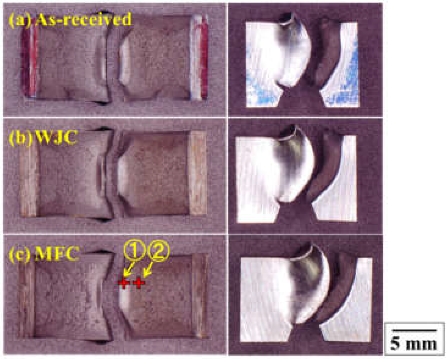
As a result of the Charpy impact test of Cr–Mo steel (SCM435), the energy value was 95.9 J for the untreated material, 99.78 J for the WJC-processed material, and 101.22 J for the MFC-processed material, and the effectiveness by functional cavitation processing became clear. The appearance of the fracture surface of each specimen is shown in
Figure 1 and
Figure 2.
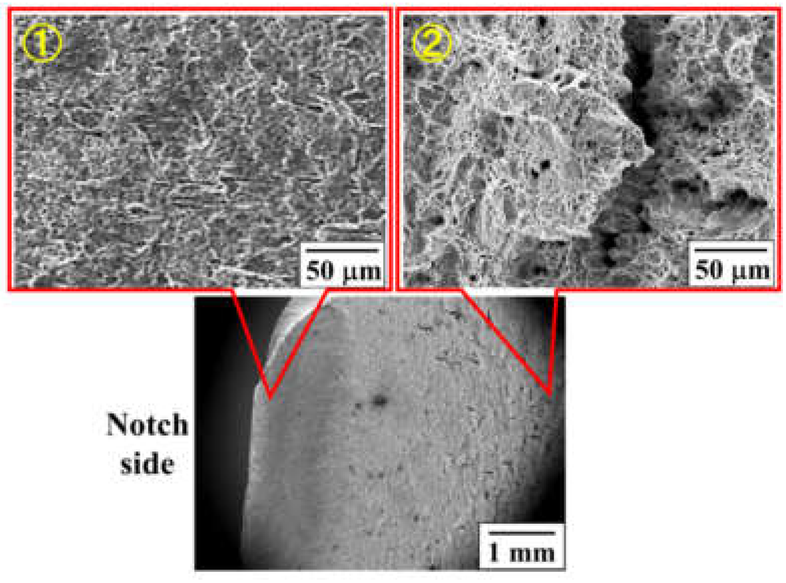
A shear lip was formed on the fracture surface of the sample after the Charpy impact test, and a ductile fracture surface and brittle fracture surface were confirmed as shown in
Figure 1 and
Figure 2. ① and ② in
Figure 1 show the position of the fracture observation, and the microscopic microstructure thereof is shown in
Figure 2.
The ductile fracture rate was WJC 77.1%, MFC was 86.9%, and as-received was 71.1%. 95.9, 99.78 and 101.22 J of the Charpy impact test results are close values to conclude that the functional cavitation processing of the ductile fracture rate was clear.
3.2. Residual Stress
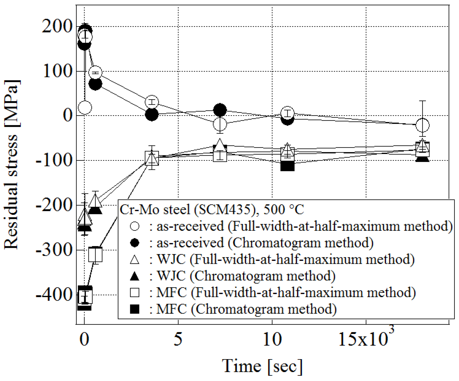
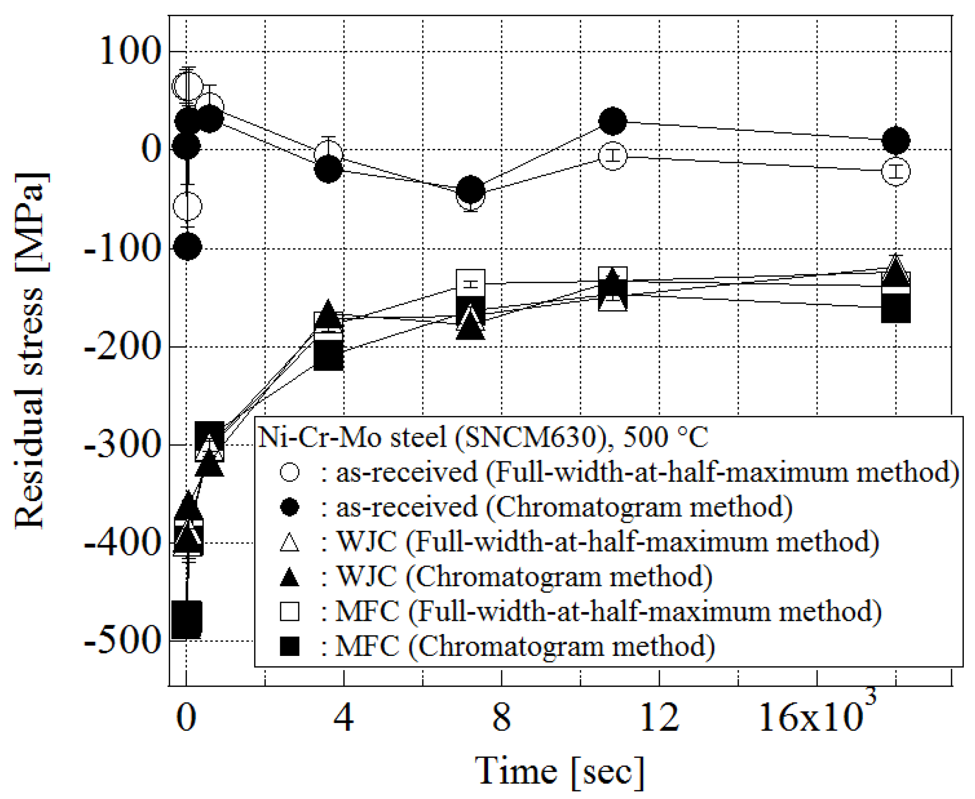
The results of the stress relaxation test at 500 °C are shown in
Figure 3 and
Figure 4.
Figure 3 shows the Cr–Mo steel (SCM435) results and
Figure 4 shows the SNCM 630 (Ni–Cr–Mo steel) results. The results of the X-ray residual stress measurement are evaluated by two kinds of methods. The outline plot in the figure is the measurement result by the half-value width method, and the solid painted plot is the measurement result by the peak top method. It was confirmed that there was a slight error (the full-width-at-half-maximum method and the chromatogram method) in some measurements but these measurements were correlated.
The initial tensile residual stress was given to the untreated material by processing the specimen surface by grinding. This was done to mitigate the shakedown effect. It is a technique for shifting to the higher compressive residual stress side due to cavitation processing by applying initial tensile residual stress to the specimen. Therefore, WJC-worked material and MFC-worked material contained high initial compressive residual stress.
It was observed that the relaxation progresses gradually with the heat treatment time of each specimen. In particular, in Cr–Mo steel (SCM435), stress relaxation was promoted between 10 and 60 min of WJC-worked material and MFC-worked material. In SNCM 630 (Ni–Cr–Mo steel), as well as Cr–Mo steel (SCM435), stress relaxation was promoted within 10 to 60 min [
11,
12]. Stress relaxation is defined as “the stress level decreases as initial elastic strain is transformed into inelastic strain”. Thus, relaxation involves a gradual transformation of elastic to inelastic strain, with the stress decreasing to maintain the proper correspondence with the remaining elastic strain [
13]. The relationship between stress relaxation of the material and residual stress is determined by the spring and dash pod of viscoelastic behavior [
14].
When comparing the WJC-processed material and the MFC-processed material, the MFC-processed material had a higher degree of workability due to the collapse of the cavitation, and the stress relaxation was further suppressed. This is because a high-temperature reaction field (hot spot) is generated inside the bubble by irradiating ultrasonic waves onto bubbles of about 100 μm generated by the water jet, and by “micro forging” (a phenomenon in which micro-level bubbles tap countless numbers of sample surfaces) the specimen surface, MFC. This is due to the fact that the machining was done further to the inside.
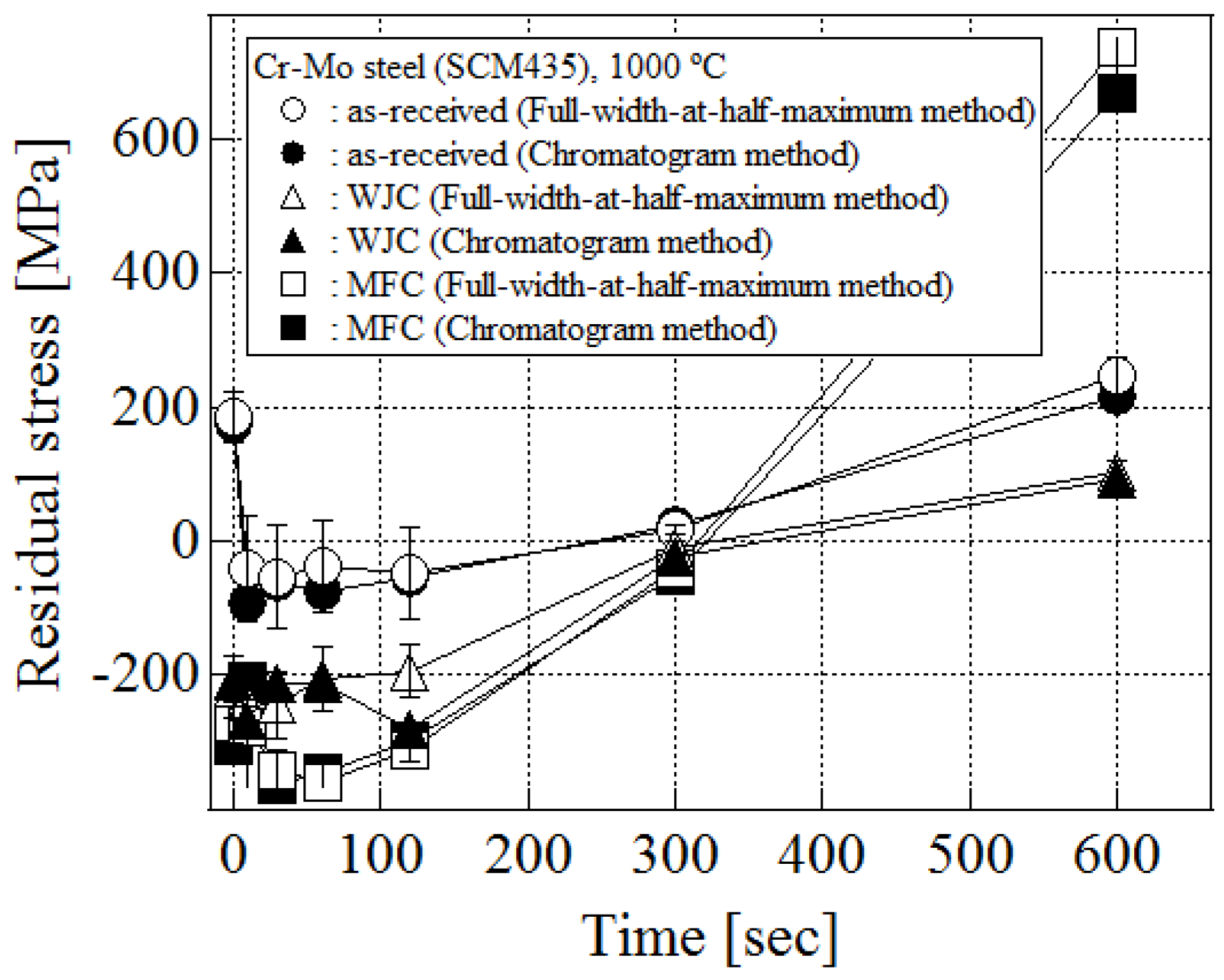
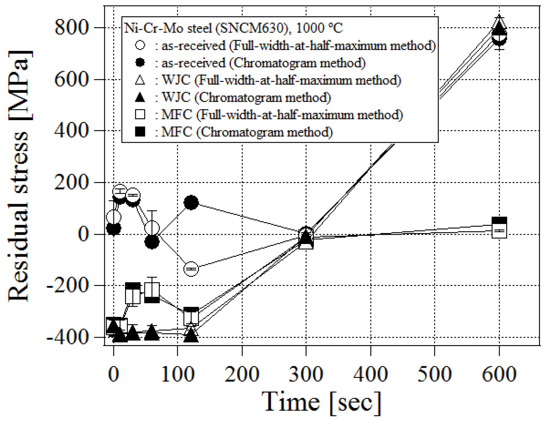
The results of the stress relaxation test at 1000 °C are shown in
Figure 5 and
Figure 6.
Figure 5 shows the Cr–Mo steel (SCM435) results and
Figure 6 shows the SNCM 630 (Ni–Cr–Mo steel) results. In Cr–Mo steel (SCM435), the stress relaxation behavior of MFC-worked material was the best, and all samples relaxed their stress in about 5 min. In SNCM 630 (Ni–Cr–Mo steel), the error was large for the unprocessed material and for the MFC-processed material was about 5 min. It is presumed that the scale formed on the specimen surface affected X-ray diffraction when heat treatment was performed.
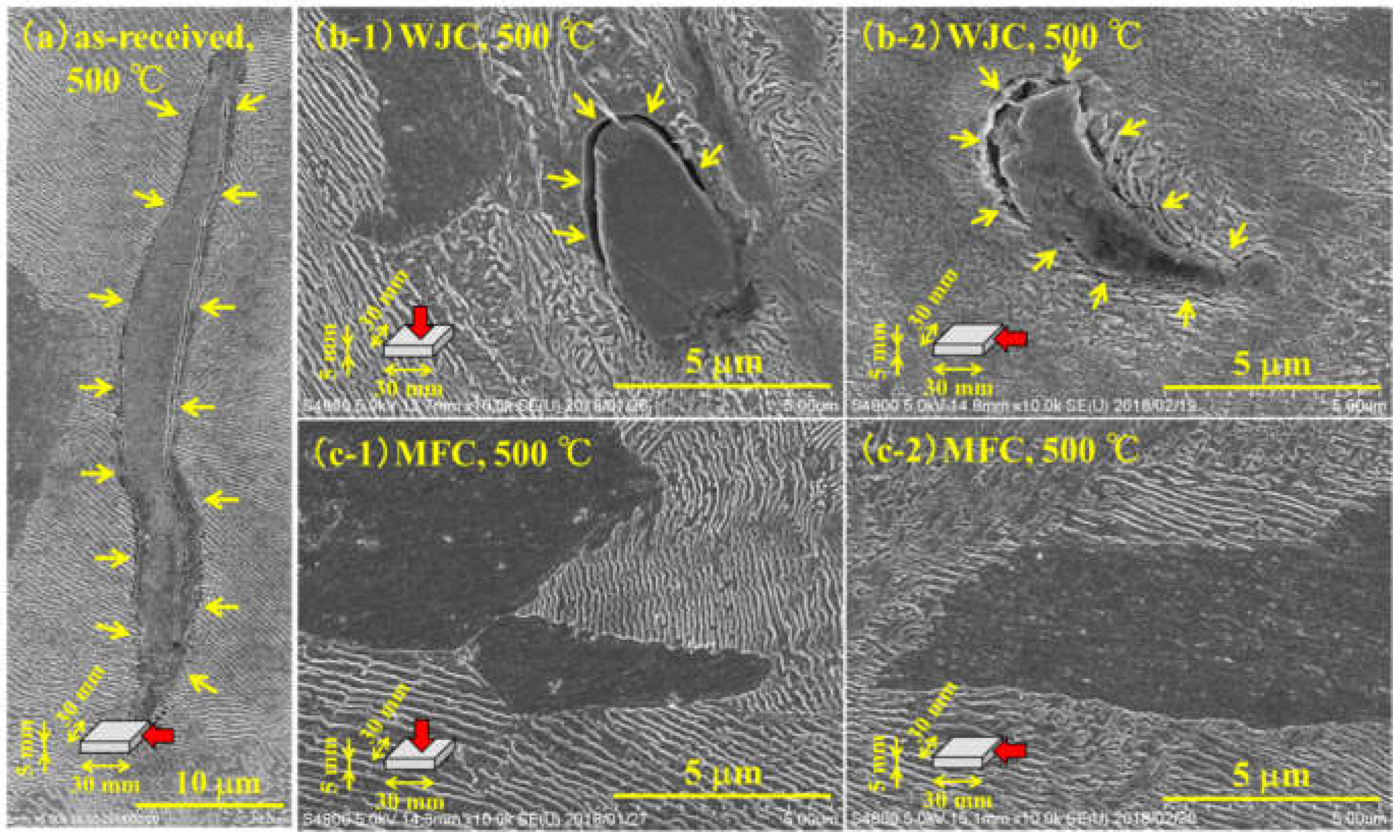
3.3. Microstructure Observation
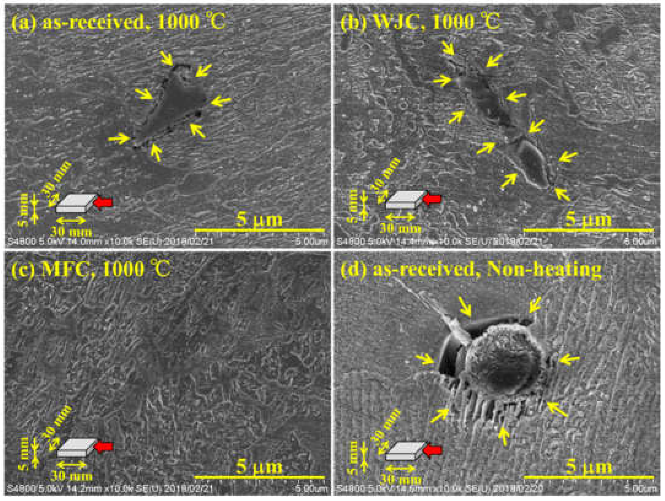
Figure 7 shows the results of microstructure surface observation of a specimen subjected to the stress relaxation test of Cr–Mo steel (SCM435) at 500 °C for 5 h. The results of observation of the microstructure of the specimen subjected to heat treatment at 1000 °C for 10 min are shown in
Figure 8. Cracks were observed in the WJC-processed material near the grain boundaries of ferrite (α phase) and pearlite (α phase and Fe
3C lamellar structure). In the MFC-processed material, cracks were not observed near the grain boundary, and only peening marks were confirmed [
15]. In the MFC-processed material, cracks were not observed near the grain boundary, and only peening marks were confirmed.
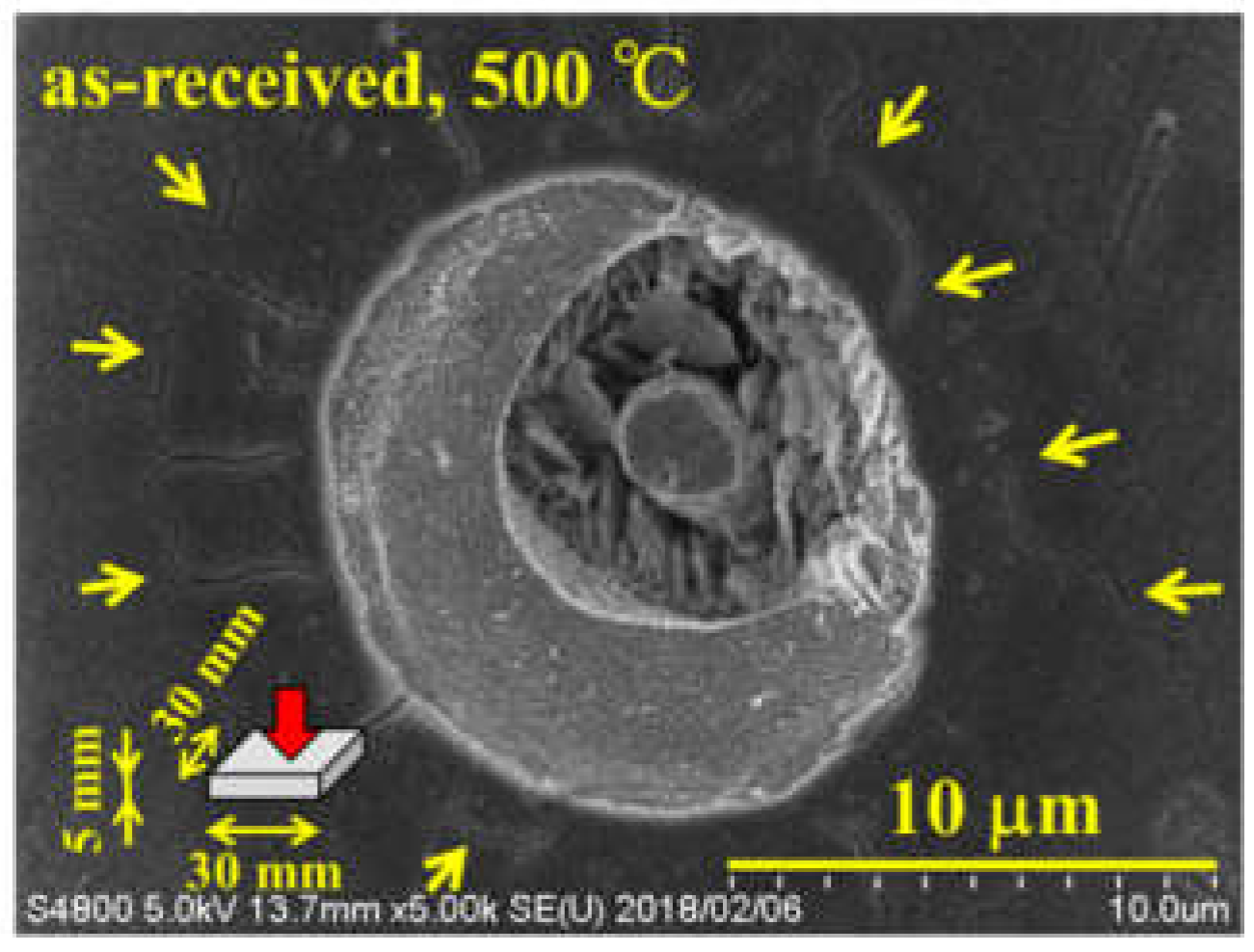
In addition, although all samples were polished and corroded under the same conditions, a large number of corrosion pits were formed in the untreated material, as shown in
Figure 9, and the existence of cracks in a radial pattern around the corrosion pits was confirmed. It is considered that this is a surface which is lower in surface potential and easily forms corrosion pits relative to the sample subjected to various cavitation processes.
From the above, it is considered that the MFC-worked material has no cracks or corrosion pits in the vicinity of the grain boundary, which can be a destruction starting point, as compared with the WJC-processed material and the untreated material, and is a processing method leading to an improvement in crack resistance. MFC processing is considered to be an effective surface modification method for parts used in a high-temperature environment. We plan to compare this with shot peened treated materials in the future.
4. Conclusions
Experimental study on stress relaxation behavior due to heat of low alloy steels subjected to high-temperature and high-pressure cavitation (MFC) processing revealed the following:
(1) Both Cr–Mo steel (SCM435) and SNCM 630 (Ni–Cr–Mo steel) showed higher values of initial compressive residual stress in MFC-worked material compared to WJC-processed material.
(2) In the stress relaxation test, under heat treatment at 500 °C for 5 h, the stress was not sufficiently relaxed and the state in which the compressive residual stress was imparted was maintained, but at 1000 °C it relaxed in about 5 min. As a result of Cr–Mo steel (SCM435) other than 1000 °C, stress relaxation was suppressed in MFC processed material compared to that in WJC processed material.
(3) In the stress relaxation test at 500 °C and 1000 °C, the MFC-worked material showed the best results with the least stress relaxation.
(4) As a result of the observation of the stress in the stress relaxation test specimens at 500 °C and 1000 °C of Cr–Mo steel (SCM435), cracks were observed near the grain boundary in the WJC-processed material, but not in the MFC processed material. In addition, a lot of corrosion pits were formed in the untreated material.
Author Contributions
All authors made a substantial contribution to this research. Conceptualization and methodology, K.T. and T.Y.; investigation, K.T.; cavitation processing, K.T., D.S., D.N. and M.I.; stress relaxation test, K.T. and D.N.; analysis, K.T.; supervision and project administration, T.Y.
Funding
This research was funded by Research Promotion Program for Military Security Technology which began from 2016–2018, the Innovative Science and Technology Initiative for Security program of the Acquisition, Technology and Logistics Agency (ATLA) of Japan.
Acknowledgments
This work was supported by Takumi Fukuda, Nobuhiro Nakamura and Kazuo Hashimoto at Yamaguchi Prefectural Industrial Technology Institute.
Conflicts of Interest
The authors declare no conflict of interest.
References
- Kobayashi, M.; Matsui, T.; Murakami, Y. Mechanism of creation of compressive residual stress by shot peening. Int. J. Fatigue 1998, 20, 351–357. [Google Scholar] [CrossRef]
- Wang, S.; Li, Y.; Yao, M.; Wang, R. Compressive residual stress introduced by shot peening. J. Mater. Process. Technol. 1998, 73, 64–73. [Google Scholar] [CrossRef]
- Torres, M.A.S.; Voorwald, H.J.C. An evaluation of shot peening, residual stress and stress relaxation on the fatigue life of AISI 4340 steel. Int. J. Fatigue 2002, 24, 877–886. [Google Scholar] [CrossRef]
- Benedetti, M.; Fontanari, V.; Scardi, P.; Ricardo, C.L.A.; Bndini, M. Reverse bending fatigue of shot peened 7075-T651 aluminium alloy: The role of residual stress relaxation. Int. J. Fatigue 2009, 31, 1225–1236. [Google Scholar] [CrossRef]
- Yoshimura, T.; Tanaka, K.; Yoshinaga, N. Development of mechanical electrochemical cavitation technology. J. Jet Flow Eng. 2016, 32, 10–17. [Google Scholar]
- Yoshimura, T. Method For Generating Mechanical and Electrochemical Cavitation, Method for Changing Geometric Shape and Electrochemical Properties of Substance Surface, Method for Peeling off Rare Metal, Mechanical and Electrochemical Cavitation Generator, and Method for Generating Nuclear Fusion Reaction of Deuterium. U.S. Patent WO2016/136656Al, 22 February 2016. [Google Scholar]
- Tanaka, K.; Yoshimura, T.; Yoshinaga, N. Study on photocatalyst properties improvement of titanium oxide by the mechanical-electrochemical cavitation. J. Jet Flow Eng. 2016, 32, 10–16. [Google Scholar]
- Tanaka, K.; Yoshimura, T.; Yoshinaga, N. A Study on low outgassing of the carbon steel by cavitation processing. J. Jet Flow Eng. 2016, 32, 4–9. [Google Scholar]
- Tanaka, K.; Ijiri, M.; Nakagawa, D.; Yoshiya, H.; Kitamikado, S.; Yoshimura, T. Surface Modification of Cr-Mo Steel by Ultra-High-Temperature and Ultra-High-Pressure Cavitation; Paper No. G0400403; The Japan Society of Mechanical Engineers, Saitama University: Saitama, Japan, 6 September 2017. [Google Scholar]
- Yamaguchi Prefectural Industrial Technology Institute. X-Ray Stress Analyzer: MSF/PSF-3M Manual (Rigaku Corporation); Yamaguchi Prefectural Industrial Technology Institute: Ube, Yamaguchi, Japan, 2016. [Google Scholar]
- Yoshimura, T.; Kitano, Y.; Shimohara, B.; Tanaka, K.; Ijiri, M.; Nakagawa, D. Thermal Shock Characteristics of Cr-Mo Steel (SCM435) by High-Temperature and High-Pressure Cavitation Processing; Paper No. P-09; Japan Research Institute of Material Technology, Tokyo University of Science: Tokyo, Japan, 2 December 2017; pp. 159–160. [Google Scholar]
- Yoshimura, T.; Shimohara, B.; Kitano, Y.; Tanaka, K.; Ijiri, M.; Nakagawa, D. Thermal Shock Characteristics of SNCM 630 (Ni-Cr-Mo Steel) by High-Temperature and High-Pressure Cavitation Processing; Paper No. P-36; Japan Research Institute of Material Technology, Tokyo University of Science: Tokyo, Japan, 2 December 2017; pp. 105–106. [Google Scholar]
- Conway, J.B.; Stentz, R.H.; Berling, J.T. Fatigue, Tensile, and Relaxation Behavior of Stainless Steels; United States Atomic Energy Commission: Washington, DC, USA, 1975; p. 228. [Google Scholar]
- Freudenthal, A.M. Effect of rheological behavior on thermal stresses. J. Appl. Phys. 1954, 25, 1110–1117. [Google Scholar] [CrossRef]
- Tanaka, K.; Kitano, Y.; Shimohara, B.; Shimonishi, D.; Nakagawa, D.; Ijiri, M.; Yoshimura, T. Stress Relaxation Behavior by Heat of Low Alloy Steel Processed by High-Pressure and High-Temperature Cavitation; Paper No. 401; The Japan Society of Mechanical Engineers Chugoku-Shikoku Branch, Tokushima University: Tokushima, Japan, 7 March 2018. [Google Scholar]
© 2019 by the authors. Licensee MDPI, Basel, Switzerland. This article is an open access article distributed under the terms and conditions of the Creative Commons Attribution (CC BY) license (http://creativecommons.org/licenses/by/4.0/).


