Experimental Study on Vibration Control of Suspended Piping System by Single-Sided Pounding Tuned Mass Damper


1
Hubei Key Laboratory of Earthquake Early Warning, Institute of Seismology, China Earthquake Administration, Wuhan 430071, China
2
Department of Mechanical Engineering, University of Houston, 4800 Calhoun, Houston, TX 77024, USA
3
Wuhan Institute of Earthquake Engineering, Wuhan 430071, China
4
Institute of Road and Bridge Engineering, Dalian Maritime University, Dalian 116023, China
*
Authors to whom correspondence should be addressed.
Appl. Sci. 2019, 9(2), 285; https://doi.org/10.3390/app9020285
Submission received: 20 December 2018
/
Revised: 10 January 2019
/
Accepted: 10 January 2019
/
Published: 15 January 2019
(This article belongs to the Special Issue Energy Dissipation and Vibration Control: Materials, Modeling, Algorithm and Devices)
Abstract
:Featured Application
The presented device aims to passively suppress the vibrations of suspended piping systems and improve structural resiliency and occupant safety.
Abstract
Suspended piping systems often suffer from severe damages when subjected to seismic excitation. Due to the high flexibility of the piping systems, reducing their displacement is important for the prevention of damage during times of disaster. A solution to protecting piping systems during heavy excitation is the use of the emerging pounding tuned mass damper (PTMD) technology. In particular, the single-sided PTMD combines the advantages of the tuned mass damper (TMD) and the impact damper, including the benefits of a simple design and rapid, efficient energy dissipation. In this paper, two single-sided PTMDs (spring steel-type PTMD and simple pendulum-type PTMD) were designed and fabricated. The dampers were tested and compared with the traditional TMD for mitigating free vibration and forced vibration. In the free vibration experiment, both PTMDs suppressed vibrations much faster than the TMD. For the forced vibration test, the frequency response of the piping system was obtained for three conditions: without control, with TMD control, and with PTMD control. These novel results demonstrate that the single-sided PTMD is a cost-effective method for efficiently and passively mitigating the vibration of suspended piping systems. Thus, the single-sided PTMD will be an important tool for increasing the resilience of structures as well as for improving the safety of their occupants.

1. Introduction
Suspended piping systems, which consist of water/gas pipes and cable ducts, play a crucial role in commercial buildings due to their functionality. However, the suspended piping systems can suffer not only from the dynamic loads induced by interior heat and fluid, but also from exterior seismic loads [1]. Often due to the lack of professional design for vibration mitigation, piping systems are more susceptible to damage than other structural components during earthquakes. Failed piping systems, depending on the situation, can lead to the loss of life and property. First, piping systems make up a considerable proportion of the total investment in most buildings [2], which means that damages to piping systems can incur high repair costs and lead to significant economic losses. Second, the damage to piping systems will induce serious secondary disasters, such as the severe and extensive flooding damage that happened in the Hawaii earthquake (2006) [3] and the Chile earthquake (2010) [4]. Furthermore, damage to the piping system may interrupt the entire building’s functionality and inflict further economic loss. In past earthquake disasters, the functional interruption of hospitals [5], fire sprinkler systems [6], and water supply systems [7] affected thousands of people for several weeks.
The results of the historical earthquake damage survey showed that a major contributor to the damage of piping systems was the large displacement of the pipes during earthquakes. Piping systems collide with surrounding components such as ceilings and beams when under large displacement [8], and the differential deformation caused by large displacement will lead to fractures in the piping system. There are two main types of suspended piping systems: one is to evenly arrange the vertical rods along the direction of a single pipe to hold the pipe (as shown in Figure 1a), and the other is to use the trapeze-shape basket to support pipes (as shown in Figure 1b). The common denominator between these two piping systems is that there are no lateral braces, which means that the lateral stiffness of the piping system is very small and allows for large displacement during earthquakes. Therefore, reducing the displacement of suspended piping system is an important issue to minimize damage during seismic activity.
Generally, there are two methods to reduce the displacement of the piping system under seismic excitation. One method is adding braces, and the other is employing dampers for vibration control. The braces connect the pipe to a fixed structure tightly, and limit the displacement of pipes. However, the limited displacement will lead to large internal forces [9,10]. Another disadvantage of the braces is that the implementation on suspended piping systems is typically impractical due to deficient space when various facilities are installed around the pipes. Dampers are often used for piping system vibration control in industrial structures such as nuclear plants [11]. Both elasto-plastic support devices [12,13] and friction dampers [14] have been studied to reduce the dynamic response of nuclear power plant pipes. Numerical studies also show that viscous fluid dampers [15] have a good prospect in the vibration control of piping systems. However, they are rarely used in non-industrial settings due to their high cost and complicated structure.
Recent decades have seen the rapid development in structural vibration control [16,17], and commonly used techniques include active vibration control [18,19,20], semi-active vibration control [21,22,23,24], passive vibration control [25,26,27,28,29,30], and hybrid vibration control [31,32,33,34,35]. Active and semi-active controls require vibration sensors [36], and due to their advantages of fast response [37], wide availability in different shapes and sizes [38,39], and low cost, piezoceramic transducers are commonly used to sense structural vibrations [40,41]. Compared to passive devices, active and semi-active controls are more effective at suppressing vibrations; however, the control devices require power sources, and components are normally more complex and more likely to fail [42]. In general, passive damping devices have the advantages of simple structure, easy maintenance, and high reliability, and have been widely implemented in mechanical, civil, and aerospace structures [43,44]. Commonly used passive vibration dampers include TMDs (tuned mass damper) [45,46], viscoelastic dampers, impact dampers [47,48], particle dampers [49,50], oil dampers, friction dampers [51,52], shape memory alloy (SMA) dampers [53,54,55], eddy current dampers [56,57,58], among others [59,60,61,62].
In addition, pounding tuned mass damper (PTMD) is a new type of passive control damper [63] that has received extensive attention in recent years [64,65,66,67,68]. It combines the advantages of the effective vibration control of a tuned mass damper (TMD), the quick energy dissipation of an impact/pounding damper, and the high energy dissipation of a viscous damper. Theoretical analysis and experimental results have demonstrated the effectiveness and efficiency of PTMD on vibration control [69,70,71], including traffic signal poles [72,73], subsea jumpers [74], and power transmission towers [75], among others. However, it has never been applied to the vibration control of a suspended piping system.
Therefore, in this paper, pounding tuned mass dampers (PTMDs) were designed to mitigate the vibration response of the suspended piping system. In the PTMD experiments, viscoelastic (VE) material was used for energy dissipation. Both TMD and PTMD were tested in free vibration and forced vibration respectively, to compare their performance regarding vibration control. The results showed that the PTMD system had good vibration control performance in both cases. The significance and originality of this work is the application of the emerging PTMD technology to suspended piping systems in an effort to increase the resilience of buildings that are prone to seismic activities and also improve the safety of the occupants therein.
2. Pounding Tuned Mass Damper (PTMD)
As reviewed in the last section, the tuned mass damper (TMD) is one of the most popular dampers because of the effectiveness in vibration suppression near the resonance frequency [76,77]. It connects a mass to the superstructure by a spring, as shown in Figure 2a, and the frequency of the spring-mass is tuned to that of the superstructure. The TMD can absorb the kinetic energy; however, its own energy cannot be dissipated effectively. Therefore, the TMD is often used with other energy dissipating components, which may require continuous maintenance [78]. In addition, a TMD’s performance is sensitive to the frequency variation of the superstructure. As shown in Figure 2b, an impact damper includes a single mass or multiple masses with motion delimiters. The impact/pounding between the mass and the delimiters dissipates energy. The impact damper has some advantages [79] such as simple construction, easy adjustment, high energy dissipation, low cost, and robustness to frequency variations.
The pounding tuned mass damper (PTMD) was developed to combine the advantages of a TMD and an impact damper with the help of viscoelastic materials [63]. Similar to a TMD, a PTMD connects the mass to the structure by a spring, and the natural frequency of the spring-mass system is tuned close to that of the superstructure. However, unlike a TMD, the displacement of the mass in the PTMD is limited by two delimiters. The spring-mass system consumes energy similar to a TMD when the displacement is small, while the collision between the mass and the delimiter effectively dissipates energy when the displacement is large. In order to improve the vibration suppression capacity during the impact, an energy-dissipating material is bonded to the delimiters. Commonly used energy dissipating materials include viscoelastic materials [80,81] and shape memory alloys [82]. Figure 2c shows the schematic of the PTMD. In addition, experimental studies have shown the good impact fatigue life of the viscoelastic materials [83]. Both analytical and experimental studies have shown that a PTMD is much more robust to frequency variation as compared to a TMD [67,70].
Based on the original double-sided PTMD proposed in [63], Wang et al. [64] proposed a novel single-sided PTMD. In the single-side PTMD, the mass is in close contact with the only delimiter in the initial equilibrium state, and the mass can move only in one direction relative to the equilibrium state, as shown in Figure 2d. This proposed method has several significant advantages, including a simple structure and ease of design, since the design parameter of the gap between the mass and the delimiter is now eliminated. Specifically, for the single-sided PTMD, the moving mass is in simple contact with the viscoeleastic delimiter during idle times. There are no preloads to press the mass against the delimiter. There is no need to design the size of the gap between the mass and the delimiter. Since there is no gap, the PTMD will not work similar to a TMD, even at low amplitudes. Additionally, the single-sided PTMD is more efficient than the double-sided PTMD regarding energy dissipation. During the working process of the single-sided PTMD, when the mass returns to the equilibrium position, the kinetic energy of the mass and the primary structure is at its maximum in the opposite direction; thus, the impact dissipates the largest amount of energy.
3. Modal Analysis of the Piping System
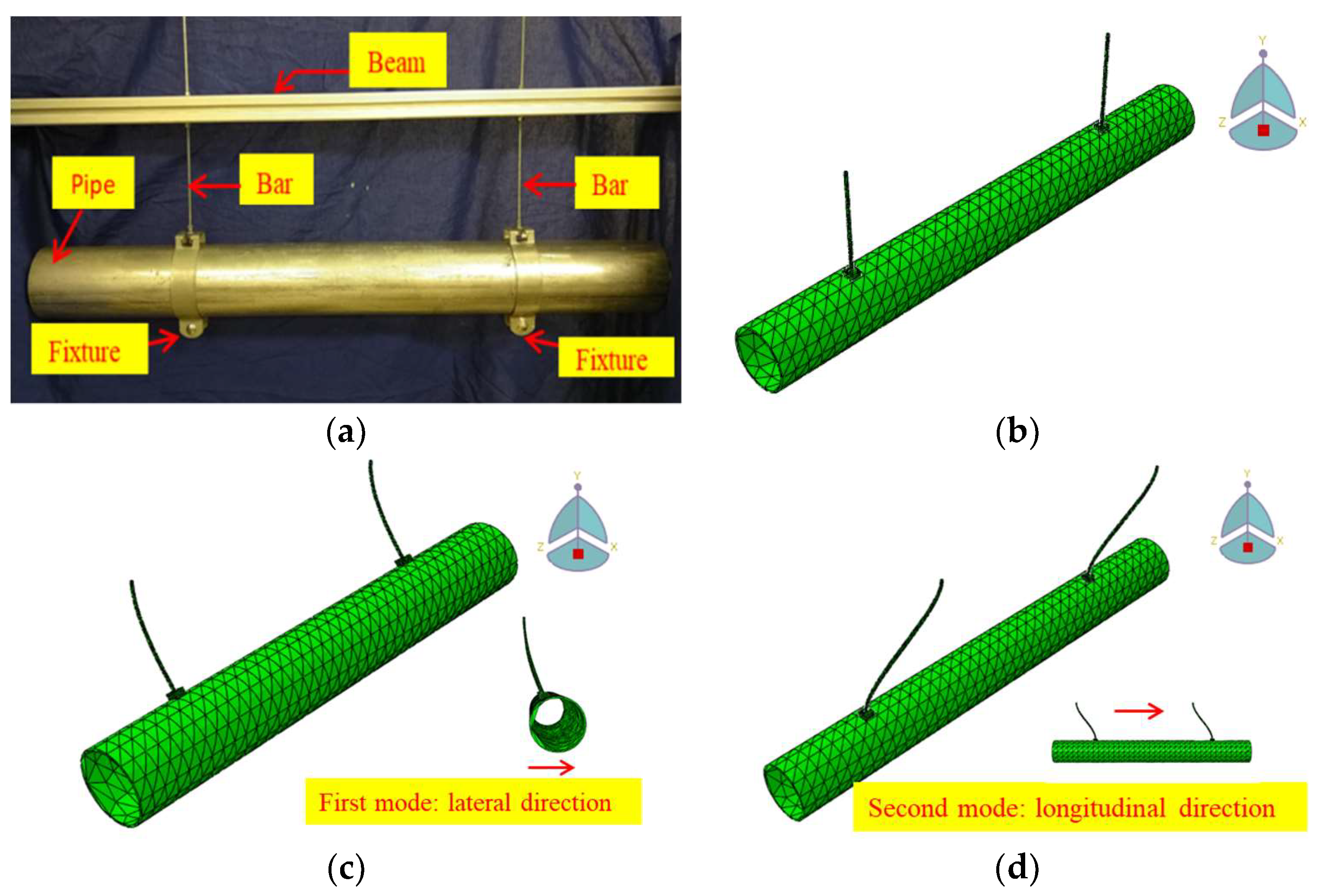
A suspended piping system that is used to transport water was selected as the experiment structure to test the effectiveness of the designed PTMDs. The piping system consists of a galvanized steel pipe, an aluminum beam, two steel bars, and fixtures, as shown in Figure 3a. Two threaded steel bars connect the pipe to the beam by fixtures. The beam in the experiment has the same rigidity as the ceiling in the actual engineering, and there is no deformation on the beam during the movement of the pipe. The length of the pipe is 1133 mm, and the length of the thread steel bars is 195 mm. The total mass of the pipe, bars, and fixtures is 9.3 kg. The detailed dimensions of the piping system are shown in Table 1. In order to understand the dynamic characteristics of the piping system, the finite element (FE) model was developed by ABAQUS, as shown in Figure 3b. According to the results of FE analysis, the first mode of the piping system is lateral movement, and the second mode is longitudinal movement, as shown in Figure 3c,d. It should be noted that due to the softness of the suspension bars compared to the pipe, all of the deformation occurred at the suspension bars, and the pipe did not experience deformation.
The natural frequencies of the first two modes are 2.54 Hz and 8.14 Hz, respectively. The first mode had low frequency and large displacement; thus, the PTMDs in this paper were designed to control the first vibration mode of the piping system. It should be noted that in practice, FE analysis will help guide the design of the PTMD. In the absence of FE analysis, experimentally-based modal analysis is a viable option. The free vibration of the piping system was tested by applying an initial displacement to the middle of the pipe. The experimental result showed that the frequency of the first mode was 2.55 Hz, and the structural equivalent viscous damping ratio was 0.58% (amplitude from 15 mm to 10 mm) using the logarithmic decrement method. Figure 4a,b show the free vibration history and the fast Fourier transform (FFT) amplitude in the frequency domain, respectively.
4. Experimental Setup
In the experiment, a TMD and a PTMD were employed separately to control the vibration of the piping system. In order to compare the effectiveness of two dampers, the mass ratio, which is an important factor in damper design, remained the same in TMD and PTMD. It is well-known that a larger mass ratio will lead to a better control effect; however, having a large mass is unfavorable for engineering applications. Thus, it is essential to select an appropriate mass ratio, whose used range in practice is from 1% to 5%. In the experiment, the same mass block (0.403 kg) was used for TMD and PTMDs, and the corresponding mass ratio is 4.33%.
In this experiment, the control fixture was placed in the middle of the pipe (Figure 5a) due to two main factors. First, by placing the control fixture in the middle of the pipe, the torsion caused by eccentricity will be reduced. The reduced torsion will improve the control efficiency of the PTMDs. Secondly, the PTMDs were leveled with the pipe, thus freeing up space above and below the pipe. The extra space may help avoid making modifications to existing suspension systems and thus facilitate the retrofitting of existing piping systems. The TMD, which was tested separately, is composed of mass and spring steel, as shown in Figure 5b. The PTMD consists of mass, a swing arm, and energy dissipation material. Two types of PTMDs were designed: one used a spring steel and the other used a simple pendulum, as shown in Figure 5c,d. Due to its stable mechanical properties and outstanding fatigue resistance, the spring steel was chosen as the swing arm of the TMD and also for one of the PTMDs. Additionally, using a simple pendulum as the swing arm of the PTMD has the advantages of simple structure and easy adjustment of the frequency.
In order to understand the dynamic characteristics of the TMD and the PTMD, free vibration tests were conducted on the spring steel-mass systems. The result shows that the frequency of TMD and PTMD was 2.55 Hz and 1.28 Hz, and the corresponding damping ratios (only of the spring steel and mass) were 0.06% and 0.04%, respectively. From previous studies, when the single-sided PTMD is working, the mass will pound the energy-dissipating material and then rebound, and the PTMD’s working frequency will be twice the free vibration frequency. In other words, since the structure’s free vibration frequency is 2.55 Hz, the PTMD frequency should be tuned to 1.28 Hz. Thus, the free vibration frequency of the single-sided PTMD is designed to be close to half the frequency of the piping system. In the experiment, viscoelastic material (3M Inc., Maplewood, MN, USA, as shown in Figure 5c) was used to dissipate energy, and its thickness was 6 mm. The detailed parameters of the TMD and PTMDs are shown in Table 2.
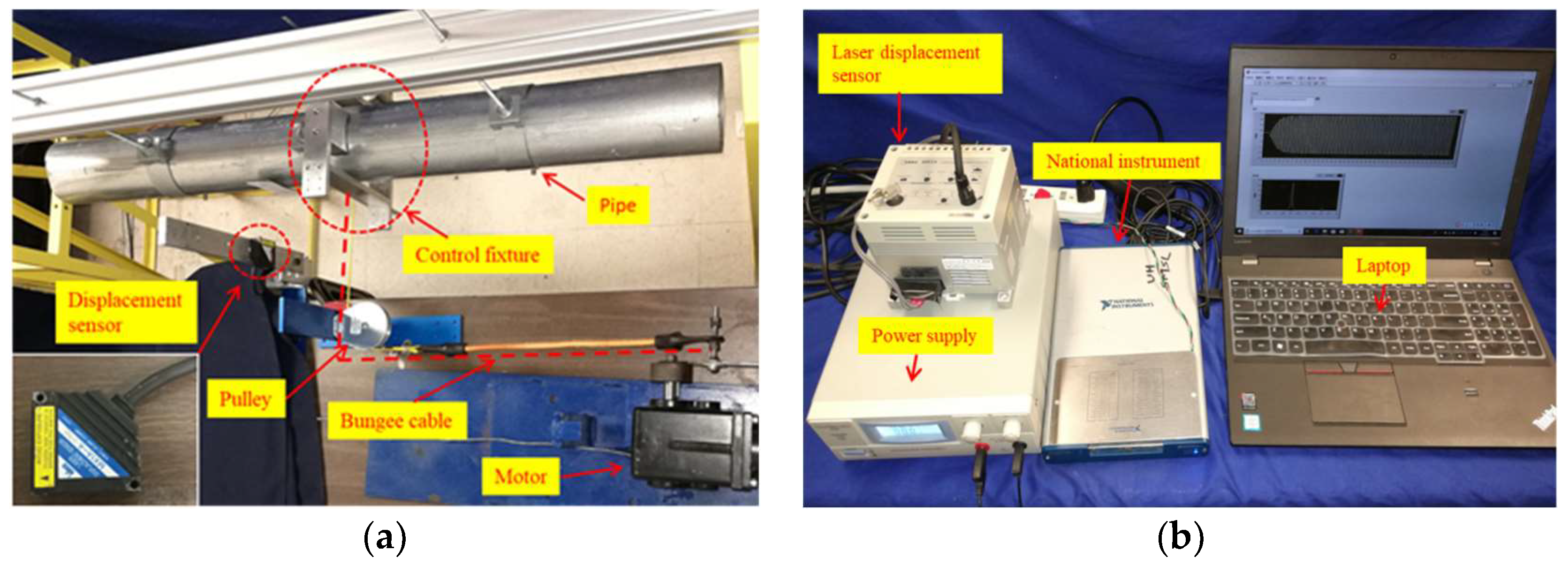
The experimental setup is shown in Figure 6a,b. A laser displacement detection sensor (MX1A-A, IDEC Sensors, Tokyo, Japan) with a maximum range of ±40 mm was used to measure the lateral horizontal displacement of the suspended piping system. The pipe displacement was generated by a wheel chair motor (DG-158A, AVIC, Beijing, China) driven by a power supply (CSI3020SW, CircuitSpecialists, Tempe, AZ, USA). Data was measured using a data acquisition card (NI USB X Series 6361, National Instruments, Austin, TX, USA) at a sampling frequency of 200 Hz. Through a rotating arm, a motor was used to excite the structure, and a bungee cable was used as a force transmission rope. One side of the bungee cable was attached to the arm of the motor, while the other side was connected to the middle of the pipe, and a pulley was used to ensure that the pipe was excited by a horizontal excitation in a single direction. In the experiment, different frequency excitations were realized by changing the rotation speed of the motor.
5. Experiment of Piping System Vibration Control
In this section, a set of experiments were conducted to compare the responses of the suspended piping system under different working conditions, including without control, with TMD control, with spring steel-type PTMD control, and with simple pendulum-type PTMD control. Each condition was tested in two loading cases: free vibration and forced vibration.
5.1. Control Performance of Free Vibration
5.1.1. Free Vibration with TMD
When the structure is controlled by TMD, the displacement attenuation of the structure becomes slower than the case without control under free vibration, as shown in Figure 7. The initial displacement of the free vibration is 20 mm. When there is no control on the piping system, the displacement attenuates to 10% of the initial value after 26.5 s. However, it takes 48.8 s to settle when the piping system is controlled through TMD.
This phenomenon can be predicted by the Den Hartog closed-form equation [87] for the optimal damping:
where ζopt is the optimal damping ratio of the TMD, and a is the mass ratio (ma is the mass of the TMD, and m is the mass of the structure). According to Equation (1), for a mass ratio of 0.433%, the optimal damping ratio is 11.96%. Since the TMD damping ratio is 0.06%, the addition of the TMD did not improve the vibration suppression, and in this case, it even amplified the vibration. The beating observed in Figure 7 was included in the settling time (48.8 s) of the vibrations.
To further understand the reason causing the low rate of attenuation, a numerical simulation was performed. Figure 8 illustrates the numerical study results of free vibration with TMD in three different cases: ζpiping > ζTMD, ζpiping = ζTMD, ζpiping < ζTMD, where ζpiping and ζTMD are the damping ratio of the piping system and the TMD. In the numerical study; the damping ratio of the piping system is 0.58%, and the damping ratios of the TMD under three cases are 0.06%, 0.58%, and 1.10%, respectively. When ζpiping > ζTMD, as shown in Figure 8a, the displacement attenuation rate of the superstructure becomes slower, which is consistent with the experimental results. When ζpiping = ζTMD, the envelope of displacement attenuation is almost identical, as shown in Figure 8b. When ζpiping < ζTMD, TMD can promote the suppression of vibration, as shown in Figure 8c.
5.1.2. Free Vibration with PTMD
Figure 9a illustrates the free vibration of the piping system with spring steel-type PTMD control. The displacement of the pipe is quickly reduced to a very small level compared to the case of without control. The time taken for suppressing displacement from 20 mm to two mm reduces from 26.5 s (uncontrolled) to 1.6 s, and the damping ratio of the system is correspondingly increased from 0.06% to 10.4%. The free vibration result for the simple pendulum-type PTMD is shown in Figure 9b. It takes 2.85 s for the displacement to decay to two mm, and the damping ratio increases to 5.6%. Two PTMDs demonstrated good performance under free vibration, and the decay times of the same displacement reduces to 6% and 10.8% of the free vibration without control. The spring steel-type PTMD adds nearly twice the damping as the simple pendulum-type PTMD, and suppresses the free vibration more efficiently.
Comparing the free vibration experiments between TMD and PTMDs, it can be observed that the PTMDs can mitigate the vibration of the piping system far more effectively than TMD. If the damping ratio of a TMD is smaller than that of the piping system, it will not suppress the vibration or may even prolong the vibration. However, both PTMDs can increase the damping ratio of the piping system significantly and stabilize the vibration within a short time.
5.2. Control Performance of Forced Vibration
In the forced vibration experiment, different frequencies of excitations are realized by changing the rotation speed of the motor. The displacement responses of the piping system under four working conditions (without control, with TMD control, with steel spring-type PTMD control, and with simple pendulum-type PTMD control) are recorded at different frequencies and plotted as a frequency-displacement curve, as shown in Figure 10.
The black line in Figure 10 is the frequency response curve of the piping system without control. When the excitation frequency is 2.57 Hz, the maximum response displacement is 18.90 mm. When the piping system is controlled by the TMD, two peaks appear on the frequency spectra of the piping system, as shown in the figure (green line). The frequencies of the two peaks are 2.12 Hz and 3.02 Hz, and the corresponding displacements are 16.98 mm and 12.86 mm, which are 90% and 68% of the uncontrolled resonant amplitude. In the frequency range of 2.3 Hz to 2.9 Hz, the TMD can effectively reduce the displacement of the piping system by more than 80%. When the excitation frequency is close to 2.6 Hz, the pipe displacement is close to zero. The blue line describes the frequency response of the piping system with the spring steel-type PTMD control. The frequency response curve only has one peak (2.46 Hz), which is on the left side of the uncontrolled resonance frequency. Additionally, the peak displacement is 9.72 mm, which is 51% of the uncontrolled resonant amplitude. Similar to spring steel-type PTMD, there is only one peak of the amplitude frequency curve controlled by the simple pendulum-type PTMD. The peak frequency is also 2.46 Hz, and the corresponding amplitude is 9.24 mm, which is 49% of the uncontrolled resonant amplitude. The appearance of only one peak after the addition of the PTMD was also observed in other cases [64,68].
At the resonance frequency (2.57 Hz) of the piping system, the control effects of the following systems are arranged in the order from largest to smallest: TMD, simple pendulum-style PTMD, spring steel-style PTMD. The corresponding displacement ratios are 3%, 42%, and 47%, respectively. Figure 11 shows the vibration responses of the piping system before and after the PTMD is released. After the release of the PTMDs, the piping system reaches a new steady state in a short time, with a displacement amplitude of about half that from before the PTMD is released. In the whole frequency domain, the rank of vibration control effectiveness under three conditions is simple pendulum-type PTMD > spring steel-type PTMD > TMD, and the corresponding displacements were reduced to 49% (Figure 12a), 51% (Figure 12b), and 90% (Figure 12c), respectively.
6. Conclusions and Future Work
In this study, two pounding tuned mass dampers (PTMDs) were designed to mitigate the vibration of a suspended piping system. A tuned mass damper (TMD) and the two designed PTMDs were tested under free vibration and forced vibration to compare their effectiveness regarding vibration control. Both spring steel-type PTMD and simple pendulum-type PTMD were investigated to verify their vibration suppression performance.
In the free vibration experiment, the TMD decreased the vibration attenuation capability of the piping system, and the time for reducing displacement from 20 mm to two mm increased from 26.5 s to 48.8 s. Both kinds of PTMDs added considerable damping (spring steel-type with 10.4% and simple pendulum-type with 5.6%) to the piping system; thus, the free vibration of the piping system was rapidly attenuated. The time taken to reduce the vibration displacement to two mm was reduced from 26.5 s (without control) to 1.6 s (with spring steel-type control) and 2.85 s (with simple pendulum-type control), respectively. The comparison shows that for this experiment, the spring steel-type PTMD is more effective.
In the forced vibration experiment, TMD can reduce the displacement of the pipe to almost zero at the tuned frequency. However, it also leads to new resonant regions on both sides of the original frequency spectra (2.12 Hz and 3.02 Hz) with displacement ratios of 90% and 68%. In the frequency domain, the amplitude frequency responses controlled by PTMDs have only one peak, which is 2.46 Hz. Both PTMDs provide considerable damping and reduce the displacement response significantly. The vibration mitigation performance of simple pendulum-type PTMD is slightly better than spring steel-type PTMD, and the displacements are reduced by 51% (simple pendulum type) and 49% (spring steel type), respectively.
In practice, there are wires, liquids, etc. in the piping system, which can affect the effectiveness of the PTMD. According to [67,70], the PTMD is robust for a moderate range of frequencies (e.g., if the PTMD is detuned or an unexpected mass is added to the pipe). If the operator can anticipate the presence of additional mass, such as liquid, the PTMD can be designed beforehand to target the expected mass of the pipe during operation. Furthermore, the larger the amplitude of vibration, the stronger the impact between the mass and the delimiter becomes. Thus, there is an inherent adaptive behavior of the PTMD to both weak and strong vibrations. However, the limit to this adaptation has not yet been explored fully, and to keep the paper concise, only a certain level of amplitude has been investigated. The effects of the nonlinearity in the PTMD on how it can adapt to different amplitudes will be our future work. Another subject for future work is the design considerations for vertically placed pipes. For vertical pipes, gravity will need to be taken into account, which will require modifications to the fixture design. Also, as can be seen in Figure 4b, multiple, smaller peaks are present alongside the peak of the structural response. These peaks, while having a negligible impact on the overall results, were neither present in the FE analysis nor in the subsequent experimental results, and are generated by a currently unknown source. Thus, another facet of future work will include a more in-depth investigation of these additional peaks. As an additional limitation of this study, the vibration excitation was generated by a harmonic load. However, the response of the piping system under earthquake load will be different from a harmonic load. Future work will investigate the vibration performance of the piping system with PTMD under an earthquake load to further verify its effectiveness.
Author Contributions
All authors discussed and agreed upon the idea, and made scientific contributions. J.T. and J.J. designed the experiments and wrote the paper. J.T., and P.Z. performed the experiments and analyzed the data. S.C.M.H. revised the paper.
Funding
The authors are grateful for financial support from the Earthquake Emergency Youth Foundation of China Earthquake Administration (CEA_EDEM-2019) and National Natural Science Foundation of China (No. 51808092). The authors would also like to thank the support from China Scholarship Council and China Earthquake Administration.
Conflicts of Interest
The authors declare no conflict of interest.
References
- Whittaker, A.S.; Soong, T.T. An overview of nonstructural components research at three US Earthquake Engineering Research Centers. In Proceedings of the ATC Seminar on Seismic Design, Performance, and Retrofit of Nonstructural Components in Critical Facilities, Newport Beach, CA, USA, 23–24 October 2003. [Google Scholar]
- Taghavi, S.; Miranda, E. Response Assessment of Nonstructural Building Elements; Pacific Earthquake Engineering Research Center: Berkeley, CA, USA, 2003. [Google Scholar]
- Chock, G. Preliminary Observations on the Hawaii Earthquakes of October 15, 2006; EERI special earthquake report; EERI: Oakland, CA, USA, 2006. [Google Scholar]
- Miranda, E.; Mosqueda, G.; Retamales, R.; Pekcan, G. Performance of nonstructural components during the 27 February 2010 Chile earthquake. Earthq. Spectra 2012, 28 (Suppl. 1), S453–S471. [Google Scholar] [CrossRef]
- Ayres, J.M.; Phillips, R.J. Water damage in hospitals resulting from the Northridge earthquake. Ashrae Trans. 1998, 104, 1286. [Google Scholar]
- Fleming, R.P. Analysis of Fire Sprinkler Systems Performance in the Northridge Earthquake; No. Grant/Contract Reports (NISTGCR)-98-736; National Institute of Standards and Technology: Gaithersburg, MD, USA, 1998. [Google Scholar]
- Goltz, J. The Northridge, California Earthquake of January 17, 1994: General Reconnaissance Report; National Center for Earthquake Engineering Research: Buffalo, NY, USA, 1994. [Google Scholar]
- Ayers, J.M.; Phillips, R. Northridge Earthquake Hospital Water Damage Study; Ayers & Ezers Associates, Inc.: Los Angeles, CA, USA, 1996. [Google Scholar]
- Zaghi, A.E.; Maragakis, E.M.; Itani, A.; Goodwin, E. Experimental and analytical studies of hospital piping assemblies subjected to seismic loading. Earthq. Spectra 2012, 28, 367–384. [Google Scholar] [CrossRef]
- Tian, Y.; Filiatrault, A.; Mosqueda, G. Seismic response of pressurized fire sprinkler piping systems I: Experimental study. J. Earthq. Eng. 2015, 19, 649–673. [Google Scholar] [CrossRef]
- Kumar, P.; Jangid, R.S.; Reddy, G.R. Comparative performance of passive devices for piping system under seismic excitation. Nucl. Eng. Des. 2016, 298, 121–134. [Google Scholar] [CrossRef]
- Chiba, T.; Kobayashi, H. Response characteristics of piping system supported by visco-elastic and elasto-plastic dampers. J. Press. Vessel Technol. 1990, 112, 34–38. [Google Scholar] [CrossRef]
- Kumar, K.S.; Muthumani, K.; Gopalakrishnan, N.; Sarma, B.S.; Reddy, G.R.; Parulekar, Y.M. Reduction of large seismic deformations using elasto-plastic passive energy dissipaters. Def. Sci. J. 2003, 53, 95–103. [Google Scholar] [CrossRef]
- Bakre, S.V.; Jangid, R.S.; Reddy, G.R. Response of piping system on friction support to bi-directional excitation. Nucl. Eng. Des. 2007, 237, 124–136. [Google Scholar] [CrossRef]
- Kostarev, V.V.; Bercovsky, A.M.; Kireev, O.B.; Vasiliev, P.S. Application of Mathematical Model for High Viscous Damper to Dynamic Analysis of NPP Pipings; No. INIS-XA–184; International Atomic Energy Agency (IAEA): Vienna, Austria, 1993. [Google Scholar]
- Soong, T.T.; Costantinou, M.C. (Eds.) Passive and Active Structural Vibration Control in Civil Engineering; Springer: Berlin, Germany, 2004; Volume 345. [Google Scholar]
- Song, G.; Cai, S.; Li, H.N. Energy Dissipation and Vibration Control: Modeling, Algorithm, and Devices. Appl. Sci. 2017, 7, 801. [Google Scholar] [CrossRef]
- Kim, B.; Yoon, J.Y. Enhanced Adaptive Filtering Algorithm Based on Sliding Mode Control for Active Vibration Rejection of Smart Beam Structures. Appl. Sci. 2017, 7, 750. [Google Scholar] [CrossRef]
- Lin, C.Y.; Jheng, H.W. Active vibration suppression of a motor-driven piezoelectric smart structure using adaptive fuzzy sliding mode control and repetitive control. Appl. Sci. 2017, 7, 240. [Google Scholar] [CrossRef]
- Gu, H.; Song, G. Active vibration suppression of a flexible beam with piezoceramic patches using robust model reference control. Smart Mater. Struct. 2007, 16, 1453. [Google Scholar] [CrossRef]
- Phu, D.X.; An, J.H.; Choi, S.B. A novel adaptive PID controller with application to vibration control of a semi-active vehicle seat suspension. Appl. Sci. 2017, 7, 1055. [Google Scholar] [CrossRef]
- Huo, L.; Song, G.; Nagarajaiah, S.; Li, H. Semi-active vibration suppression of a space truss structure using a fault tolerant controller. J. Vib. Control 2012, 18, 1436–1453. [Google Scholar] [CrossRef]
- Demetriou, D.; Nikitas, N.; Tsavdaridis, K.D. Semi active tuned mass dampers of buildings: A simple control option. Am. J. Eng. Appl. Sci. 2015, 8, 620–632. [Google Scholar] [CrossRef]
- Li, L.; Song, G.; Ou, J. A genetic algorithm-based two-phase design for optimal placement of semi-active dampers for nonlinear benchmark structure. J. Vib. Control 2010, 16, 1379–1392. [Google Scholar] [CrossRef]
- Wang, Z.; Chen, Z.; Gao, H.; Wang, H. Development of a self-powered magnetorheological damper system for cable vibration control. Appl. Sci. 2018, 8, 118. [Google Scholar] [CrossRef]
- He, B.; Ouyang, H.; Ren, X.; He, S. Dynamic response of a simplified turbine blade model with under-platform dry friction dampers considering normal load variation. Appl. Sci. 2017, 7, 228. [Google Scholar] [CrossRef]
- Suarez, E.; Roldán, A.; Gallego, A.; Benavent-Climent, A. Entropy analysis for damage quantification of hysteretic dampers used as seismic protection of buildings. Appl. Sci. 2017, 7, 628. [Google Scholar] [CrossRef]
- Kang, J.D.; Mori, Y. Evaluation of a Simplified Method to Estimate the Peak Inter-Story Drift Ratio of Steel Frames with Hysteretic Dampers. Appl. Sci. 2017, 7, 449. [Google Scholar] [CrossRef]
- Fu, W.; Zhang, C.; Sun, L.; Askari, M.; Samali, B.; Chung, K.L.; Sharafi, P. Experimental investigation of a base isolation system incorporating MR dampers with the high-order single step control algorithm. Appl. Sci. 2017, 7, 344. [Google Scholar] [CrossRef]
- Gastaldi, C.; Fantetti, A.; Berruti, T. Forced response prediction of turbine blades with flexible dampers: The impact of engineering modelling choices. Appl. Sci. 2018, 8, 34. [Google Scholar] [CrossRef]
- Kim, H.; Adeli, H. Hybrid control of smart structures using a novel wavelet-based algorithm. Comput.-Aided Civ. Infrastruct. Eng. 2005, 20, 7–22. [Google Scholar] [CrossRef]
- Ozbulut, O.E.; Hurlebaus, S. Application of an SMA-based hybrid control device to 20-story nonlinear benchmark building. Earthq. Eng. Struct. Dyn. 2012, 41, 1831–1843. [Google Scholar] [CrossRef]
- Demetriou, D.; Nikitas, N. A novel hybrid semi-active mass damper configuration for structural applications. Appl. Sci. 2016, 6, 397. [Google Scholar] [CrossRef]
- Meinhardt, C.; Nikitas, N.; Demetriou, D. Application of a 245 metric ton Dual-Use Active TMD System. Procedia Eng. 2017, 199, 1719–1724. [Google Scholar] [CrossRef]
- Demetriou, D.; Nikitas, N.; Tsavdaridis, K.D. Performance of fixed-parameter control algorithms on high-rise structures equipped with semi-active tuned mass dampers. Struct. Des. Tall Spec. Build. 2016, 25, 340–354. [Google Scholar] [CrossRef]
- Wang, H.; Li, L.; Song, G.; Dabney, J.B.; Harman, T.L. A new approach to deal with sensor errors in structural controls with MR damper. Smart Struct. Syst. 2015, 16, 329–345. [Google Scholar] [CrossRef]
- Wang, F.; Ho, S.C.M.; Huo, L.; Song, G. A novel fractal contact-electromechanical impedance model for quantitative monitoring of bolted joint looseness. IEEE Access 2018, 6, 40212–40220. [Google Scholar] [CrossRef]
- Aoki, Y.; Gardonio, P.; Elliott, S.J. Modelling of a piezoceramic patch actuator for velocity feedback control. Smart Mater. Struct. 2008, 17, 015052. [Google Scholar] [CrossRef]
- Wang, F.; Huo, L.; Song, G. A piezoelectric active sensing method for quantitative monitoring of bolt loosening using energy dissipation caused by tangential damping based on the fractal contact theory. Smart Mater. Struct. 2017, 27, 015023. [Google Scholar] [CrossRef] [Green Version]
- Sethi, V.; Song, G. Optimal vibration control of a model frame structure using piezoceramic sensors and actuators. Modal Anal. 2005, 11, 671–684. [Google Scholar] [CrossRef]
- Narayanan, S.; Balamurugan, V. Finite element modelling of piezolaminated smart structures for active vibration control with distributed sensors and actuators. J. Sound Vib. 2003, 262, 529–562. [Google Scholar] [CrossRef]
- Saaed, T.E.; Nikolakopoulos, G.; Jonasson, J.E.; Hedlund, H. A state-of-the-art review of structural control systems. J. Vib. Control 2015, 21, 919–937. [Google Scholar] [CrossRef]
- Li, H.; Wang, S.Y.; Song, G.; Liu, G. Reduction of seismic forces on existing buildings with newly constructed additional stories including friction layer and dampers. J. Sound Vib. 2004, 269, 653–667. [Google Scholar] [CrossRef]
- Attary, N.; Symans, M.; Nagarajaiah, S.; Reinhorn, A.M.; Constantinou, M.C.; Sarlis, A.A.; Pasala, D.T.; Taylor, D. Numerical simulations of a highway bridge structure employing passive negative stiffness device for seismic protection. Earthq. Eng. Struct. Dyn. 2015, 44, 973–995. [Google Scholar] [CrossRef]
- Taniguchi, T.; Der Kiureghian, A.; Melkumyan, M. Effect of tuned mass damper on displacement demand of base-isolated structures. Eng. Struct. 2008, 30, 3478–3488. [Google Scholar] [CrossRef]
- Bae, J.S.; Hwang, J.H.; Roh, J.H.; Kim, J.H.; Yi, M.S.; Lim, J.H. Vibration suppression of a cantilever beam using magnetically tuned-mass-damper. J. Sound Vib. 2012, 331, 5669–5684. [Google Scholar] [CrossRef]
- Cheng, J.; Xu, H. Inner mass impact damper for attenuating structure vibration. Int. J. Solids Struct. 2006, 43, 5355–5369. [Google Scholar] [CrossRef] [Green Version]
- Egger, P.; Caracoglia, L.; Kollegger, J. Modeling and experimental validation of a multiple-mass-particle impact damper for controlling stay-cable oscillations. Struct. Control Health Monit. 2016, 23, 960–978. [Google Scholar] [CrossRef]
- Hu, L.; Shi, Y.; Yang, Q.; Song, G. Sound reduction at a target point inside an enclosed cavity using particle dampers. J. Sound Vib. 2016, 384, 45–55. [Google Scholar] [CrossRef]
- Lu, Z.; Chen, X.; Zhang, D.; Dai, K. Experimental and analytical study on the performance of particle tuned mass dampers under seismic excitation. Earthq. Eng. Struct. Dyn. 2017, 46, 697–714. [Google Scholar] [CrossRef]
- Choi, E.; Choi, G.; Kim, H.T.; Youn, H. Smart damper using the combination of magnetic friction and pre-compressed rubber springs. J. Sound Vib. 2015, 351, 68–89. [Google Scholar] [CrossRef]
- Qian, H.; Li, H.; Song, G. Experimental investigations of building structure with a superelastic shape memory alloy friction damper subject to seismic loads. Smart Mater. Struct. 2016, 25, 125026. [Google Scholar] [CrossRef]
- Song, G.; Ma, N.; Li, H.N. Applications of shape memory alloys in civil structures. Eng. Struct. 2006, 28, 1266–1274. [Google Scholar] [CrossRef]
- Sawaguchi, T.; Maruyama, T.; Otsuka, H.; Kushibe, A.; Inoue, Y.; Tsuzaki, K. Design concept and applications of Fe–Mn–Si-based alloys—From shape-memory to seismic response control. Mater. Trans. 2016, 57, 283–293. [Google Scholar] [CrossRef]
- Li, H.; Liu, M.; Ou, J. Vibration mitigation of a stay cable with one shape memory alloy damper. Struct. Control Health Monit. 2004, 11, 21–36. [Google Scholar] [CrossRef]
- Sodano, H.A.; Bae, J.S.; Inman, D.J.; Belvin, W.K. Concept and model of eddy current damper for vibration suppression of a beam. J. Sound Vib. 2005, 288, 1177–1196. [Google Scholar] [CrossRef]
- Wang, W.; Dalton, D.; Hua, X.; Wang, X.; Chen, Z.; Song, G. Experimental study on vibration control of a submerged pipeline model by eddy current tuned mass damper. Appl. Sci. 2017, 7, 987. [Google Scholar] [CrossRef]
- Chen, J.; Lu, G.; Li, Y.; Wang, T.; Wang, W.; Song, G. Experimental study on robustness of an eddy current-tuned mass damper. Appl. Sci. 2017, 7, 895. [Google Scholar] [CrossRef]
- Lu, Z.; Yang, Y.; Lu, X.; Liu, C. Preliminary study on the damping effect of a lateral damping buffer under a debris flow load. Appl. Sci. 2017, 7, 201. [Google Scholar] [CrossRef]
- Zhang, Z.; Ou, J.; Li, D.; Zhang, S. Optimization design of coupling beam metal damper in shear wall structures. Appl. Sci. 2017, 7, 137. [Google Scholar] [CrossRef]
- Palacios-Quiñonero, F.; Rubió-Massegú, J.; Rossell, J.M.; Karimi, H.R. Integrated design of hybrid interstory-interbuilding multi-actuation schemes for vibration control of adjacent buildings under seismic excitations. Appl. Sci. 2017, 7, 323. [Google Scholar] [CrossRef]
- Kaloop, M.R.; Hu, J.W.; Bigdeli, Y. Identification of the response of a controlled building structure subjected to seismic load by using nonlinear system models. Appl. Sci. 2016, 6, 301. [Google Scholar] [CrossRef]
- Song, G.; Li, L.; Singla, M.; Mo, Y.L. Pounding Tune Mass Damper with Viscoelastic Material. U.S. Patent 9,500,247, 2016. [Google Scholar]
- Wang, W.; Hua, X.; Wang, X.; Chen, Z.; Song, G. Numerical modeling and experimental study on a novel pounding tuned mass damper. J. Vib. Control 2018, 24, 4023–4036. [Google Scholar] [CrossRef]
- Lin, W.; Wang, Q.; Li, J.; Chen, S.; Qi, A. Shaking table test of pounding tuned mass damper (PTMD) on a frame structure under earthquake excitation. Comput. Concr. 2017, 20, 545–553. [Google Scholar]
- Yin, X.; Liu, Y.; Song, G.; Mo, Y.L. Suppression of Bridge Vibration Induced by Moving Vehicles Using Pounding Tuned Mass Dampers. J. Bridge Eng. 2018, 23, 04018047. [Google Scholar] [CrossRef]
- Jiang, J.; Zhang, P.; Patil, D.; Li, H.N.; Song, G. Experimental studies on the effectiveness and robustness of a pounding tuned mass damper for vibration suppression of a submerged cylindrical pipe. Struct. Control Health Monit. 2017, 24, e2027. [Google Scholar] [CrossRef]
- Xue, Q.; Zhang, J.; He, J.; Zhang, C.; Zou, G. Seismic control performance for Pounding Tuned Massed Damper based on viscoelastic pounding force analytical method. J. Sound Vib. 2017, 411, 362–377. [Google Scholar] [CrossRef]
- Xue, Q.; Zhang, J.; He, J.; Zhang, C. Control performance and robustness of pounding tuned mass damper for vibration reduction in SDOF structure. Shock Vib. 2016, 2016, 8021690. [Google Scholar] [CrossRef]
- Li, H.-N.; Zhang, P.; Song, G.; Patil, D.; Mo, Y. Robustness study of the pounding tuned mass damper for vibration control of subsea jumpers. Smart Mater. Struct. 2015, 24, 095001. [Google Scholar] [CrossRef]
- Lin, W.; Song, G.; Chen, S. PTMD control on a benchmark TV tower under earthquake and wind load excitations. Appl. Sci. 2017, 7, 425. [Google Scholar] [CrossRef]
- Li, L.; Song, G.; Singla, M.; Mo, Y.L. Vibration control of a traffic signal pole using a pounding tuned mass damper with viscoelastic materials (II): Experimental verification. J. Vib. Control 2015, 21, 670–675. [Google Scholar] [CrossRef]
- Zhao, N.; Lu, C.; Chen, M.; Luo, N.; Liu, C. Parametric Study of Pounding Tuned Mass Damper Based on Experiment of Vibration Control of a Traffic Signal Structure. J. Aerosp. Eng. 2018, 31, 04018108. [Google Scholar] [CrossRef]
- Song, G.; Zhang, P.; Li, L.Y.; Singla, M.; Patil, D.; Li, H.N.; Mo, Y.L. Vibration control of a pipeline structure using pounding tuned mass damper. J. Eng. Mech. 2016, 142, 04016031. [Google Scholar] [CrossRef]
- Zhang, P.; Song, G.; Li, H.N.; Lin, Y.X. Seismic control of power transmission tower using pounding TMD. J. Eng. Mech. 2012, 139, 1395–1406. [Google Scholar] [CrossRef]
- Li, Q.; Fan, J.; Nie, J.; Li, Q.; Chen, Y. Crowd-induced random vibration of footbridge and vibration control using multiple tuned mass dampers. J. Sound Vib. 2010, 329, 4068–4092. [Google Scholar] [CrossRef]
- Caetano, E.; Cunha, Á.; Moutinho, C.; Magalhães, F. Studies for controlling human-induced vibration of the Pedro e Inês footbridge, Portugal. Part 2: Implementation of tuned mass dampers. Eng. Struct. 2010, 32, 1082–1091. [Google Scholar] [CrossRef]
- Collette, F.S. A combined tuned absorber and pendulum impact damper under random excitation. J. Sound Vib. 1998, 216, 199–213. [Google Scholar] [CrossRef]
- Duncan, M.R.; Wassgren, C.R.; Krousgrill, C.M. The damping performance of a single particle impact damper. J. Sound Vib. 2005, 286, 123–144. [Google Scholar] [CrossRef]
- Feng, Q.; Fan, L.; Huo, L.; Song, G. Vibration Reduction of an Existing Glass Window through a Viscoelastic Material-Based Retrofit. Appl. Sci. 2018, 8, 1061. [Google Scholar] [CrossRef]
- Wang, W.; Hua, X.; Wang, X.; Chen, Z.; Song, G. Advanced Impact Force Model for Low-Speed Pounding between Viscoelastic Materials and Steel. J. Eng. Mech. 2017, 143, 04017139. [Google Scholar] [CrossRef]
- Seo, J.; Kim, Y.C.; Hu, J.W. Pilot study for investigating the cyclic behavior of slit damper systems with recentering shape memory alloy (SMA) bending bars used for seismic restrainers. Appl. Sci. 2015, 5, 187–208. [Google Scholar] [CrossRef]
- Zhang, P.; Huo, L.; Song, G. Impact Fatigue of Viscoelastic Materials Subjected to Pounding. Appl. Sci. 2018, 8, 117. [Google Scholar] [CrossRef]
- Wang, W.; Hua, X.; Wang, X.; Chen, Z.; Song, G. Optimum design of a novel pounding tuned mass damper under harmonic excitation. Smart Mater. Struct. 2017, 26, 055024. [Google Scholar] [CrossRef]
- Wang, W.; Wang, X.; Hua, X.; Song, G.; Chen, Z. Vibration control of vortex-induced vibrations of a bridge deck by a single-side pounding tuned mass damper. Eng. Struct. 2018, 173, 61–75. [Google Scholar] [CrossRef]
- Allen, J.K.; Patil, D.; Ho, S.C.M.; Hirsch, R.; Zhang, P.; Parvasi, S.M.; Song, G. Application of the Pounding Tuned Mass Damper to a Submerged Jumper Experiencing Horizontal and Vertical Vibrations. Earth Space 2016, 2016, 1109. [Google Scholar]
- Den Hartog, J.P. Mechanical Vibrations; Courier Corporation: North Chelmsford, MA, USA, 1985. [Google Scholar]
Figure 1.
Two kinds of suspended piping systems: (a) A single rod piping system; (b) A trapeze piping system.
Figure 1.
Two kinds of suspended piping systems: (a) A single rod piping system; (b) A trapeze piping system.

Figure 2.
Schematic of (a) tuned mass damper (TMD); (b) Impact damper; (c) Double-sided pounding tuned mass damper (PTMD); (d) Single-sided PTMD.
Figure 2.
Schematic of (a) tuned mass damper (TMD); (b) Impact damper; (c) Double-sided pounding tuned mass damper (PTMD); (d) Single-sided PTMD.

Figure 3.
Piping system model and its finite element model: (a) Suspended piping system; (b) Finite element (FE) model; (c) First vibration mode shape; (d) Second vibration mode shape.
Figure 3.
Piping system model and its finite element model: (a) Suspended piping system; (b) Finite element (FE) model; (c) First vibration mode shape; (d) Second vibration mode shape.

Figure 4.
Displacement response and its fast Fourier transform (FFT) amplitude of the pipe (measured by the laser displacement sensor near the middle of the pipe): (a) Free vibration response; (b) FFT amplitude.
Figure 4.
Displacement response and its fast Fourier transform (FFT) amplitude of the pipe (measured by the laser displacement sensor near the middle of the pipe): (a) Free vibration response; (b) FFT amplitude.

Figure 5.
(a) Control fixture installed on piping system; (b) Tuned mass damper (TMD) only; (c) Spring steel-type pounding tuned mass damper (PTMD) in idle state; (d) Simple pendulum-type PTMD in idle state.
Figure 5.
(a) Control fixture installed on piping system; (b) Tuned mass damper (TMD) only; (c) Spring steel-type pounding tuned mass damper (PTMD) in idle state; (d) Simple pendulum-type PTMD in idle state.

Figure 6.
Experimental setup: (a) Forced excitation system with motor; (b) Data acquisition system.

Figure 7.
Experiment results of free vibration with TMD.

Figure 8.
Numerical results of free vibration with TMD control: (a) ζpiping > ζTMD; (b) ζpiping = ζTMDζTMD; (c) ζpiping < ζTMDζTMD.
Figure 8.
Numerical results of free vibration with TMD control: (a) ζpiping > ζTMD; (b) ζpiping = ζTMDζTMD; (c) ζpiping < ζTMDζTMD.

Figure 9.
Experimental results of free vibration: (a) With spring steel-type PTMD; (b) With simple pendulum-type PTMD.
Figure 9.
Experimental results of free vibration: (a) With spring steel-type PTMD; (b) With simple pendulum-type PTMD.

Figure 10.
Experiment results of forced vibration.

Figure 11.
Experiment results of forced vibration with PTMD released: (a) Spring steel-type PTMD; (b) Simple pendulum-type PTMD.
Figure 11.
Experiment results of forced vibration with PTMD released: (a) Spring steel-type PTMD; (b) Simple pendulum-type PTMD.

Figure 12.
Comparison of resonant vibration: (a) With simple pendulum-type PTMD; (b) With spring steel-type PTMD; (c) With TMD.
Figure 12.
Comparison of resonant vibration: (a) With simple pendulum-type PTMD; (b) With spring steel-type PTMD; (c) With TMD.


Table 1.
Dimension of the piping system.
| No. | Component | Description | Value |
|---|---|---|---|
| 1 | Pipe | Material | Steel |
| Outer diameter (mm) | 115 | ||
| Wall thickness (mm) | 2.1 | ||
| Length (mm) | 1133 | ||
| Weight (kg) | 6.68 | ||
| 2 | Fixtures | Weight (kg) | 2.62 |
| 3 | Bar | Material | Steel |
| Diameter of thread (mm) | 6.35 | ||
| Length (mm) | 195 | ||
| 4 | Beam | Material | Aluminum |
| Length (mm) | 1220 | ||
| Width (mm) | 80 | ||
| Height (mm) | 40 |
Table 2.
Parameters of TMD and PTMDs.
| TMD | Frequency of the spring steel-mass system | 2.55 Hz | |
| Component | Description | Value | |
| Spring steel | Material | Spring steel | |
| Length (mm) | 79 | ||
| Width (mm) | 20 | ||
| Thickness (mm) | 0.4 | ||
| PTMD (Spring Steel Type) | Frequency of the spring steel-mass system | 1.28 Hz | |
| Component | Description | Value | |
| Spring steel | Material | Spring steel | |
| Length (mm) | 170 | ||
| Width (mm) | 6.5 | ||
| Thickness (mm) | 0.4 | ||
| Energy-dissipating material | VE material (6 mm) | ||
| PTMD (Simple Pendulum Type) | Frequency of the simple pendulum-mass system | 1.28 Hz | |
| Component | Description | Value | |
| Nylon rope | Material | Nylon | |
| Length (mm) | 128 | ||
| Energy-dissipating material | VE material (6 mm) | ||
| Mass for TMD and PTMDs | Material | Steel | |
| Weight (kg) | 0.403 | ||
© 2019 by the authors. Licensee MDPI, Basel, Switzerland. This article is an open access article distributed under the terms and conditions of the Creative Commons Attribution (CC BY) license (http://creativecommons.org/licenses/by/4.0/).
Share and Cite
MDPI and ACS Style
Tan, J.; Michael Ho, S.C.; Zhang, P.; Jiang, J. Experimental Study on Vibration Control of Suspended Piping System by Single-Sided Pounding Tuned Mass Damper. Appl. Sci. 2019, 9, 285. https://doi.org/10.3390/app9020285
AMA Style
Tan J, Michael Ho SC, Zhang P, Jiang J. Experimental Study on Vibration Control of Suspended Piping System by Single-Sided Pounding Tuned Mass Damper. Applied Sciences. 2019; 9(2):285. https://doi.org/10.3390/app9020285
Chicago/Turabian StyleTan, Jie, Siu Chun Michael Ho, Peng Zhang, and Jinwei Jiang. 2019. "Experimental Study on Vibration Control of Suspended Piping System by Single-Sided Pounding Tuned Mass Damper" Applied Sciences 9, no. 2: 285. https://doi.org/10.3390/app9020285
Note that from the first issue of 2016, this journal uses article numbers instead of page numbers. See further details here.