Abstract
This article presents the description of the mechanism of selected dysfunctions of the human skeletal system and internal organs. The problem is wide and requires extensive experimental and numerical research. This article presents the outline of the problem regarding the creation of personal injuries of soldiers inside armored vehicles. The explanation of the mechanism of injuries caused as a result of strong effects of pulse forces, resulting from both the consequences of the wave of pressure created during an explosion, as well as high accelerations of the vehicle’s hull, is presented herein. Examples of the results of numerical analyses of the pressure wave impact from an explosion are presented in the Article. LS-Dyna software was used to perform the numerical calculations. The analyses were carried out using the Conwep algorithm implemented in the calculation code. The significance of calculation methods, thanks to which it is possible to recreate a simulation in which there is a risk of injuries of soldiers without posing a threat to their health and life, should be noted here. The main parts of the human body, such as the bottom limb, the pelvic belt, the cervical spine and the abdomen, have been considered. Mechanisms causing typical injuries of soldiers inside vehicles under which explosives are detonated have been analyzed for particular body parts through multiple numerical simulations. The analysis of the process of injury creation has been conducted on the basis of the statistical data regarding the most common injuries of soldiers. The validation process of numerical analyses was carried out using the results of experimental research.
1. Introduction
Stabilization missions and armed conflicts entail the risk of the loss of health or life caused by personal injuries. According to the statistics published in HFM-090 [1]. Improvised Explosive Devices (IEDs) constituted the most common cause of death and personal injuries of soldiers fighting in Iraq and Afghanistan between 2001 and 2010.
Improvised mines pose a threat to the health and life of soldiers who conduct routine tasks during patrols, transport and convoys. Light armoured vehicles are exposed to the effects of the majority of explosives which the opposite side has at its disposal. As part of preventing and combating the use of IEDs, all measures aiming at ensuring the safety of soldiers are undertaken. Companies which manufacture armoured vehicles constantly search for better materials characterised by bigger ballistic efficiency and bigger efficiency of absorbing the energy of the above-mentioned explosives in order to provide the highest level of safety for armies [2,3].
The cervical spine, due to its location, is the most exposed and the least protected part of the entire spine. Therefore, it is the most vulnerable to injuries [4]. The mechanism of traumatological injuries is connected with ad hoc overloading of the limit values of the strength of given spinal structures [5]. At the moment of a mine explosion, a shock wave is created, and it propagates in all directions at a speed faster than the speed of sound. The shock wave creates a pulse which triggers high acceleration in a few milliseconds and causes injuries, as well as death of the crew (HFM-090). There have been many attacks where the lower extremities of soldiers are exposed to injury. Most often, IED attacks have resulted in tibia fractures, open wounds and even limb amputation [6].
For more than ten years, two of the biggest wars in Afghanistan (2001–currently) and Iraq (2003–2011) have led to the death of around 58,000 coalition soldiers. Injuries of the musculoskeletal system were caused in 69–82% by the explosive force of Improvised Explosive Devices (IEDs) and Explosively Formed Penetrators (EFPs), whereas around 20–30% of them were caused as a result of firing or other mechanisms. The explosion of IEDs under and/or next to a vehicle, which was not unsealed but only deformed, resulted in the generation of strong acceleration. Depending on the location of an explosive, the explosion causes either the throwing of the body up and then collision of the head with the vehicle’s roof or creation of injuries caused by shearing forces resulting from side/transversal acceleration [7]. The most well-known form of head protection are helmets. There are many scientific publications about head protection using protective helmets, e.g., [8,9].
2. Analysis Regarding the Risk of Injuries
Post-explosion personal injuries caused as a result of using IEDs are extremely common in the battlefield environment, especially in the regions of asymmetric conflicts, namely guerrilla actions and terrorist threats. The force of explosive detonation and complex injury mechanisms, resulting from different acceleration vectors, fragmentation wounds, collisions with objects, squeezing, toxic inhalation, burns and other factors, have an influence on the death rate of the vehicle crew. Breaking the armour usually causes fatal injuries among crew members, not only due to direct splinter damage but also sudden decompression caused by the depressurising of the cabin compartments [10].
Pelvic injuries are typical injuries caused in the seat-occupant touch point during axial and side loading created by the effects of an explosive on a vehicle. Many of them are the most serious injuries of the locomotor organ which are accompanied by concussion, injuries of internal organs and a high death rate of those injured (10–50%). There are two main mechanisms leading to pelvic injuries: side compression and front-back compression.
The size of pelvis fractures differs from small ones (e.g., unplaced fracture of the ala) to life-threatening fractures (e.g., due to haemorrhage or damage to the bladder and bowels). Most pelvis fractures are stable and can be treated with non-surgical methods. Fractures of both pubic bones and one of them are observed most frequently (around 70% of cases). Fractures of the pelvic bones are qualified in one of three categories:
- Fractures of pelvic girdle bones
- Fractures of the acetabulum
- Post-traumatic detachment of small fragments of the pelvic bones [11].
Fractures created as a result of a side injury are divided into three types (Figure 1):
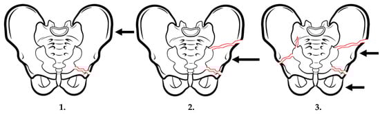
Figure 1.
Pelvic injuries caused as a result of side impacts (pelvis side compression). Own study based on [12].
- Fractures of the sacrum on the side of the injury with one-sided or two-sided bone edge damage (most common type)
- Fractures of the hip bone ala on the side of the injury
- Fractures of the sacrum on the opposite side of the injury
As in the case of fractures resulting from a side injury, fractures caused by a front-back injury can also be divided into three types (Figure 2):
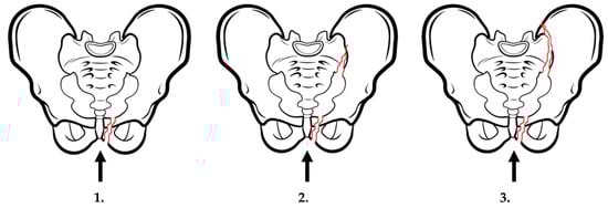
Figure 2.
Pelvic fractures caused as a result of front-back injuries (pelvis front-back compression). Own study based on [12].
- Fracture of pubic bones with the rupture of the pubic symphysis without injuries around ligaments joining bones of the rear part of the pelvic girdle;
- Partial rupture of the sacroiliac ligament being a consequence of injuries of the front part of the sacroiliac ligament, the sacrotuberous ligament and the sacrospinous ligament. This fracture type is usually accompanied by the rupture of the pubic symphysis or the fracture of the pubic bone brachia. The rear part of the sacroiliac ligament is not injured;
- Total rupture of the sacroiliac ligament with damage of bones of the front part of the pelvic girdle, similar to type 2.
Vertical fractures are a consequence of an injury longitudinally affecting the front or rear part of the pelvis girdle. Injuries of the front part can cause the rupture of the pubic symphysis, as well as one-sided or two-sided fractures of the pubic bone brachia. Injuries of the rear part of the girdle usually damage the sacroiliac ligament as well as the hip bone and the sacrum.
Taking into consideration seat belts which are the standard equipment of the seat system, when discussing injuries caused by the seat, injuries also resulting from the operation of seat belts should be included in that category.
On the basis of the analysis of medical tests conducted in the orthopaedic clinic of the Military Institute of Medicine in Warsaw on the group of 211 patients (soldiers) injured in a stabilization mission in Afghanistan, the following pelvis injuries have been stated [13]:
- Contusion of the bottom part of the back and the pelvis—57 cases—21.11%;
- Superficial injury of the abdomen, bottom part of the back and the pelvis—12 cases—4.44%;
- Fracture of the lumbar spine and the pelvis—2 cases—0.74%;
- Dislocation, twisting and strain of joints and ligaments of the lumbar spine and the pelvis—2 cases—0.74%.
The group of patients was constituted by the participants of events where IEDs were used in attacks on military vehicles.
The issue of modelling the effects of pulse loads on the body of vehicle occupants during dynamic loads is a difficult issue because multiple aspects have to be considered: the mass of an explosive, the place taken in the vehicle and personal data: age, height or body mass [14]. In the global sense, it is important to determine the behaviour of the body in order to check e.g., which vehicle elements the body has contact with; whereas in the local sense, the model analysis renders it possible to explain and understand the mechanisms underlying specific injuries of bones, tendons, ligaments and soft tissues. The models of the entire body, i.e., THUMS, are usually used in order to generally learn about the consequences of the effects of pulse loads on the body [15]. At the same time, many extended models of lower limbs [16] and clothing, e.g., shoes, are being developed [17].
In the case of a load in the form of a wave of pressure coming from an IED explosion, the cervical spine is a very sensitive part of the soldier’s body. The cervical spine, due to its location, is the most exposed and the least protected part of the entire spine. Therefore, it is the most vulnerable to injuries. The mechanism of traumatological injuries is connected with ad hoc overloading of the limit values of the strength of given spinal structures [5].
The spine is the most primary and important element of the locomotor system of vertebrates. In the case of humans, it has three basic functions: it is the locomotor organ, provides protection of the spinal cord and it is the organ of body support [18,19]. In terms of its functions, the spine constitutes support for the head and upper body parts, allows for a wide range of movement and protects the spinal cord, which contributed to its complex physical structure [5,20].
In mechanical terms, bones are complex composite and anisotropic structures with spongy texture, the structure of which is strictly connected with the value of transferred loads [21]. The bone tissue consists of the organic protein part (35%) and non-organic mineral part (65%) in the form of hydroxyapatite.
According to the statistics of armed conflicts in Iraq and Afghanistan (Figure 3), the biggest number of spinal injuries among soldiers were caused by the effects of explosives, mostly IEDs, and then transport accidents or shots [22].
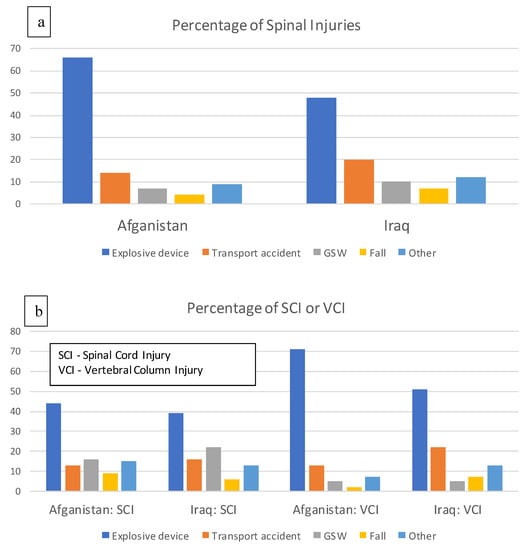
Figure 3.
Causes and types of spinal injuries of soldiers participating in missions in Iraq and Afghanistan: percentage of spinal injuries – a, percentage of SCI or VCI injuries – b. Own study based on [22].
Spinal injuries caused by explosions often result in unusual or rare fractures [23]. While neck and spine contusions constitute only 5% of the total injuries observed in current armed conflicts, the actual injuries are the worst [23]. In the case of a mine explosion under a vehicle (Figure 4), the most frequent mechanisms of injury occurs in the third explosion phase [24].
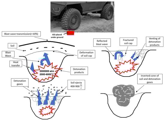
Figure 4.
Physics of a mine explosion under a vehicle. Own study based on [25].
Injuries of vehicle occupants result from the transmission of load through the floor, overturning and instability of the vehicle and the effects of the pressure of explosion [25,26]. Vertical accelerations cause spinal injuries in the cervical and lumbar spine which result from the compressive mechanism. This causes vertebral fractures. Many injuries connected with an explosion are caused as a result of mutual interactions between the vehicle and the vehicle occupant [27].
On the basis of a literature review, it is clear that injuries in the cervical spine occur in extreme segments [28]. The injury type depends on the place and manner of loading tissue structures. The injuries of upper segments are connected with the applied force from the skull to the atlanto-occipitai joint, whereas the injuries of bottom segments are connected with the effects of the force directly on the vertebral body or several adjacent segments [29].
On the basis of the analysis of medical tests conducted in the orthopaedic clinic of the Military Institute of Medicine in Warsaw, the twisting and strain of the cervical spine in the case of 15 patients were stated, which constitutes the share of 5.56%. The same type of injury was diagnosed in the Department of Battlefield Medicine in 36 patients, which constitutes the percentage share of 22.93%. Therefore, the cervical spine together with the pelvis constitute elements which are very often exposed to injuries.
The latest report of the Congressional Research Service presents the current data regarding the number of fatalities among soldiers serving in Iraq and Afghanistan between 2006 and 2019. Since 2006, the total of 4536 soldiers active in service have died and 45% of deaths were caused by Improvised Explosive Devices (IED).
3. Modelling of the Detonation Process of Mines or IEDs and the Propagation of the Shock Wave
Military vehicles should comply with special requirements in the field of protection against mines and IEDs. The NATO documents and the documents of institutes cooperating with NATO constitute the basis for determining requirements regarding the protection levels of the crew members of military vehicles against the shock wave of the explosion of mines and they also present the test methodology (e.g., a size of an explosive or its location towards a vehicle) which should be applied to every vehicle’s construction.
There are a few known methods which enable the numerical description of the detonation phenomenon and its effects on the construction. The most famous functions for the majority of packages intended for engineering calculations are the following: CONWEP, Arbitrary Lagrangian-Eulerian (ALE) and Smooth Particle Hydrodynamics (SPH) [30]. Each of them has a different way of preparing the model, the so-called numerical cost, and the type of output data which can be obtain through those functions.
In order to estimate the maximum values of pressure at the front of the incident wave, the dependencies specified by Brode, Henrych, Naumienko and Petrowski have been used and applied in the LS-DYNA system [31] and they have been implemented in the LOAD_BLAST_ENHANCED procedure. The variable in all models is constituted by a reduced distance. It is defined as:
where:
- R—distance between the observation point and the explosion point,
- MTNT—TNT mass equivalent for the considered explosion.
In the case of the dependency specified by Borde, the maximum value of overpressure ps is described with the following dependency (the value in bars, Z in [m⋅kg−1/3]):
when: 0.1 < ps < 10 bar.
The dependency specified by Henrych is presented by the following formula (the value in bars, for 1 < Z < 10):
Naumienko and Petrowski provide the following dependency in order to calculate the maximum overpressure (the value bars, for 1 < Z < 15):
In the case of a risk of a mine explosion, the detonation of an explosive located on the ground is more interesting than a free explosion in the air. The value of pressure in such a case is higher because it is strengthened as a result of interactions with the ground. In the case of an explosion on the perfectly rigid ground, the maximum value of pressure would correspond to the pressure generated for an explosive of twice the mass. However, due to the ground susceptibility, this value is smaller. The value of pressure at the front of the wave can be calculated using the following formula [32]:
where: A-G—equation coefficients dependent on Z. for Z in the range from 2.9 to 23.8 m/kg1/3 have the following values: A = 7.5938, B = −0.0523, C = 0.4098, D = 0.0261, E = −0.0127, F = G = 0.
The LOAD_BLAST_ENHANCED procedure implemented in the LS-DYNA system has been developed on the basis of the papers of Randers and Bannister from 1997 [30].
The scope of use of this procedure includes:
- For the explosion of a spherical load in the air—2.7 up to 750 load radiuses,
- For the explosion of a hemispheric load in the proximity of the ground—2.6 up to 600 load radiuses.
For that reason, it is assumed that the scope of use includes the distance of the obstacle from the centre of the load of approx. 3 to 600 times bigger than the radius of the explosive. If the obstacle is placed too close to the load, a warning is generated; however, calculations are not interrupted.
The value of pressure of the reflected wave depends on the pressure of the incident wave and the angle between the normal straight line to the considered element and the part connecting the centre of the element and the centre of the explosive. The normal straight line to the element has to be pointed towards the load. The value of pressure of the reflected wave is determined on the basis of the following dependency:
where:
- pI—pressure of the incident wave,
- pR—pressure of the reflected wave (2⋅pI ≤ pR ≤ 13⋅pI depending on the value of pressure) for = 90°,
- θ—angle of wave incidence.
In the case of angles bigger than 90°, the value of pressure is equal to the pressure of the incident wave. The lack of possibility to imitate secondary wave reflections (e.g., during an explosion in limited space) and the shadow phenomenon in the case when there is an obstacle between the load and the considered construction constitute the basic limitation of this method. The algorithm used in the calculations considers the strengthening of the interaction resulting from the detonation of the load placed in a cast steel pot. This option can be enabled in the LOAD_BLAST_ENHANCED card.
4. Subject and Scope of the Tests
For the purposes of numerical analyses, a vehicle model with protective panels installed under the vehicle and on its side wall was prepared. The conditions of placing explosives and their mass reflected assumptions made during experimental tests. Two analysis variants were carried out:
- simulation of an explosion of 6kg TNT with the explosive placed under the vehicle;
- simulation of an explosion of 15 kg TNT with the explosive placed next to the vehicle;
The central explosion was carried out on the basis of the test methodology included in AEP-55 vol. 2 (Figure 5a), whereas in the case of the side explosion, the test was conducted in the limited scope of the test methodology included in AEP-55 vol. 3 (Figure 5b).
Figure 5.
Way of placing the explosive towards the vehicle: (a) central explosion, (b) explosion next to the vehicle.
The variants of protective system mounting are presented in the Figure below (Figure 6).
Figure 6.
The vehicle with the mounted protective system: (a) for the explosion under the vehicle, (b) for the explosion next to the vehicle.
In order to solve the problem, the finite element method (FEM) with the closed-form scheme of integration was chosen. LS-Dyna software was used as the solver for calculations. The spatial discretisation of the physical system was built using finite elements and the number of finite elements in particular models is presented in Table 1.

Table 1.
Number of elements in numerical models.
Loading with the shock wave coming from the explosion has been carried out using the CONWEP model coupled with the traction boundary condition. The pressure generated from the explosion of the load was applied to the entire surface of the protective panels for both the explosion under the vehicle and the side explosion with LOAD_BLAST_SEGMENT_SET card.
The material model of a modified Johnson-Cook model has been used to describe the properties of the armoured metal plate (Table 2). The components made of S355 structural steel have been modelled using the linear and plastic model (Table 3) [33].
Table 2.
Material properties for Armstal 500 steel for the MAT_MODIFIED_JOHNSON_COOK material model.
Table 3.
Material properties for S355 steel for the MAT_PIECEWISE_LINEAR_PLASTICITY material model.
The total of 22 contact cards have been described in the numerical models, including the following types:
- CONTACT_TIED_NODES_TO_SURFACE_OFFSET, which received only the translation degrees of freedom in contact points.
- CONTACT_TIED_SHELL_EDGE_TO_SURFACE_OFFSET, in which all translation and rotation degrees of freedom are blocked.
Measuring points have also been included in the model by introducing measuring elements in them using the ELEMENT_SEATBELT_ACCELEROMETER card. The measurement has been conducted with the registration frequency of 0.5 µs.
The total mass of the object, together with energy-absorbing panels corresponding to the real construction, has been achieved by using mass elements distributed in the front and rear part of the vehicle using RBE3 elements. This, in turn, has rendered it possible to achieve the total vehicle mass of 11.3 t.
Calculations have been stabilized in the initial phase by activating the dynamic relaxation option (CONTROL_DYNAMIC_RELAXATION card), which enables a free fall of the vehicle under the pull of gravity. The calculation phase has been established at 200 ms.
5. Results and Discussion
The validation of the numerical model has been conducted through numerical analyses on the basis of the results of experimental tests carried out together with the Military Institute of Armoured and Automotive Technology. As part of the numerical model validation, the results obtained on the basis of the data from measurements conducted using the Hybrid III 50th Fast anthropomorphic dummy for the variant of the explosion under the vehicle and the EuroSID-2re anthropomorphic dummy for the simulation of the explosion next to the vehicle have been compared.
The view of the dummies in the real conditions and in the numerical analyses are presented in the Figures below (Figure 7, Figure 8).
Figure 7.
The view of the Hybrid III 50th Fast dummy during the experimental tests and in the numerical model
Figure 8.
The view of the EuroSID-2re dummy during the experimental tests and in the numerical model
Measurement results obtained from the experimental tests and numerical calculations are presented in Table 4.
Table 4.
Comparison of the results obtained on the basis of the experimental tests and numerical calculations.
The obtained characteristic of force in the dummy’s tibia is presented in a graphic way in Figure 9.
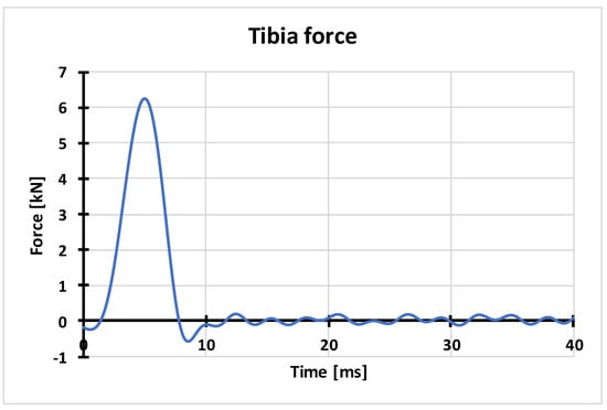
Figure 9.
Characteristic of axial force in the dummy’s tibia obtained on the basis of numerical calculations.
The above characteristic presents the axial force in the bottom part of the dummy’s tibia at the moment of an explosion. The peak of 6.25 kN shown in the characteristic chart is a consequence of loading the vehicle’s floor with the wave of pressure coming from the detonation of an explosive placed under the vehicle. The kinetic energy of the floor increases affecting the dummy’s feet resting on it and then the dummy’s tibia. The critical value of compressive axial force in the tibia, according to AEP-55, Vol. 2, is 5.4 kN. The obtained compressive fore of 6.25 kN is higher than the critical value and thus can lead to a tibia injury. The characteristic of compressive axial force in the dummy’s neck is presented in Figure 10.
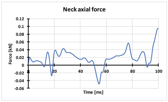
Figure 10.
Characteristic of axial force in the dummy’s neck obtained on the basis of numerical calculations.
The characteristic of axial force in the dummy’s neck, obtained as a result of the conducted numerical analysis, allows for reading the extreme values of the maximum compressive and stretching force. The value of the maximum stretching axial force in the dummy’s neck was 0.095 kN. According to the criterion included in AEP-55, Vol. 3, the critical value of this parameter is 1.8 kN, and thus there is no risk of permanent injuries. The force in the dummy’s neck with the value of 0.08 kN, obtained on the basis of experimental tests, is close to the value obtained in the numerical analysis.
Figure 11 presents the characteristic of force versus time in the dummy’s abdomen. The force with the value of 0.0149 kN, obtained on the basis of the numerical analysis, is higher by 25% than the force obtained during experimental tests. In both cases, the critical value specified at the level of 1.8 kN has not been exceeded.
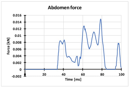
Figure 11.
Characteristic of axial force in the dummy’s abdomen obtained on the basis of numerical calculations.
The characteristic of pubic force in the dummy’s pelvis is presented in Figure 12.
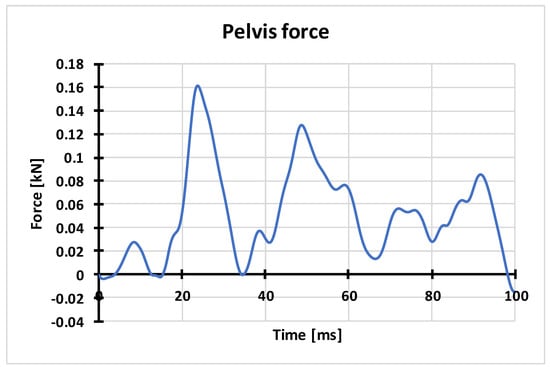
Figure 12.
Characteristic of pubic force obtained on the basis of numerical calculations.
The characteristic of force in the dummy’s pelvis presents the pubic force value in the time function for the first 100 ms of the analysis. The maximum value of the force of 0.16 kN has been obtained. The critical value of the pubic force in the pelvis, according to AEP-55, Vol. 3, is 2.6 kN. The obtained maximum value of the pubic force for experimental tests and numerical calculations is significantly lower than the critical value, which means that there is no risk of injury in that area. The characteristics of the pelvis acceleration (Figure 13) show that the greatest accelerations occurred in the z-axis direction and are the result of the seat - dummy interaction.
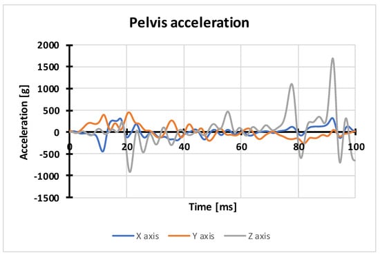
Figure 13.
Characteristic of acceleration in the dummy’s pelvis obtained on the basis of numerical calculations.
6. Conclusions
The risk of a threat to the life and health of the crew increases as a result of a detonation of an explosive under a military vehicle. The effects of the shock wave cause interactions resulting in vibrations coming from the vibration of the vehicle’s construction. The model of the body of a wheeled armoured vehicle has been subjected to the analysis of the influence of the shock wave coming from the detonation of an explosive placed in accordance with AEP-55 vol. 2 and vol. 3 on the construction. The obtained results have rendered it possible to assess the effectiveness of the construction elements responsible for providing protection against mines to crew members in the case of the detonation under the crew compartment.
The presented dysfunctions of the locomotor system are confirmed by both the statistics of the most common injuries, as well as in descriptions of incidents in which soldiers were injured. The obtained test results regarding the cervical spine clearly prove that blows to the back of the head are dangerous to life due to a high risk of damage to the spinal cord. Therefore, situations in which such shock loads occur should be avoided.
Special attention should be paid in the pelvic belt to the danger connected with significantly loading the ischium and the pubic bone. Those are structures which have an indirect contact with the seat and thus are significantly exposed to fractures. Usually, the pubic symphysis is damaged; however, in the case of big flexibility of the symphysis, one-sided or two-sided fracture of the pubic bone can occur.
The possibility of analysing cases of attacks on vehicles and their crews on the battlefield constitutes invaluable help in the process of improving the safety of soldiers serving in stabilization missions. Deep analysis of events requires considering numerous external factors. Imitating the conditions of an attack in a real way would be dangerous due to the necessity of risking the health and life of people participating in an experiment; therefore, such a project is not possible to be implemented in any real way. Complicated numerical analyses using developed models give us a chance to safely test the processes accompanying the phenomenon of the detonation of an explosive affecting the vehicle and its crew. Moreover, the results obtained this way can be then broadly interpreted and the models can be freely modified and further developed, conducting multi-variant numerical analyses without threatening the health and life of people.
Author Contributions
Conceptualization, G.S., P.M. and M.Ś.; methodology, G.S., P.M. and M.Ś.; software, G.S., P.M. and M.Ś.; validation, G.S., P.M. and M.Ś.; formal analysis, G.S., P.M. and M.Ś.; investigation, G.S., P.M. and M.Ś.; resources, G.S., P.M. and M.Ś.; data curation, G.S., P.M. and M.Ś.; writing—original draft preparation, G.S., P.M. and M.Ś.; writing—review and editing, G.S., P.M. and M.Ś.; visualization, G.S., P.M. and M.Ś.; supervision, G.S., P.M. and M.Ś.; project administration, G.S.; funding acquisition, G.S.
Funding
The research was done within project no. DOBR-BIO4/022/13149/2013 ’Improving the Safety and Protection of Soldiers on Missions Through Research and Development in Military Medical and Technical Areas’, supported and co-financed by NCR&D, Poland.
Acknowledgments
Support given by the National Centre for Research and Development of Poland and Ministry of Science and Higher Education of Poland.
Conflicts of Interest
The authors declare no conflict of interest.
References
- Test Methodology for Protection of Vehicle Occupants Against Anti-Vehicular Landmine Effects; RTO Technical Report TR–HFM-090; Neuilly-sur-Seine: Paris, France, 2007.
- Sławiński, G.; Niezgoda, T.; Barnat, W. Numerical analysis of the influence of blast wave on human body. J. KONES 2013, 20, 381–386. [Google Scholar]
- Sławiński, G.; Świerczewski, M.; Malesa, P. Modelling and numerical analysis of explosion underneath the vehicle. J. KONES 2017, 24, 279–286. [Google Scholar]
- Wolański, W.; Larysz, D. Biomechanika Stabilizacji Kręgosłupa Szyjnego; Bel Studio: Warszawa, Poland, 2011. [Google Scholar]
- Będziński, R. Biomechanika Inżynierska: Zagadnienia Wybrane; Oficyna Wydawnicza Politechniki Wrocławskiej: Wrocław, Poland, 1997. [Google Scholar]
- Ramasamy, A.M.; Hill, A.M.; Clasper, J.C. Improvised explosive devices: Pathophysiology, injury profiles, and current medical management. J. R. Army Med. Corps 2009, 155, 265–272. [Google Scholar] [CrossRef] [PubMed]
- Wolf, S.J.; Bebarta, V.S.; Bonnett, C.J.; Pons, P.T.; Cantrill, S.V. Blast injuries. Lancet 2009, 374, 405–415. [Google Scholar] [CrossRef]
- Fernandes, F.A.O.; Alves de Sousa, R.J.; Ptak, M.; Migueis, G. Helmet Design Based on the Optimization of Biocomposite Energy-Absorbing Liners under Multi-Impact Loading. Appl. Sci. 2019, 9, 735. [Google Scholar] [CrossRef]
- Jamroziak, K.; Bajkowski, M.; Bocian, M.; Polak, S.; Magier, M.; Kosobudzki, M.; Stepien, R. Ballistic Head Protection in the Light of Injury Criteria in the Case of the Wz.93 Combat Helmet. Appl. Sci. 2019, 9, 2702. [Google Scholar] [CrossRef]
- Krzystała, E.; Mężyk, A.; Kciuk, S. Analiza oddziaływania wybuchu na kołowe pojazdy specjalne i ich załogi. Szybkobieżne Pojazdy Gąsienicowe 2011, 2, 99–110. [Google Scholar]
- Gaździk, T. Ortopedia i Traumatologia; PZWL: Warsaw, Poland, 2008. [Google Scholar]
- Drhem. Available online: https://drhem.wordpress.com/tag/trauma/page/2/ (accessed on 28 November 2011).
- Wojtkowski, M.; Ziółek, J.; Waliński, T.; Płomiński, J. Description of the Patient’s Health Profile Veteran PMC Afghanistan, Based on an Assessment of Post-Traumatic Musculoskeletal Injuries; Military Institute of Medicine: Warsaw, Poland, 2016. [Google Scholar]
- Noureddine, A.; Eskandarian, A.; Digges, E. Computer Modeling and Validation of a Hybrid III Dummy for Crashworthiness Simulation. Math. Comput. Model. 2002, 35, 885–893. [Google Scholar] [CrossRef]
- Golman, A.J.; Danelson, K.A.; Stitzel, J.D. Injury prediction in a side impact crash using human body model simulation. Accid. Anal. Prev. 2014, 64, 1–8. [Google Scholar] [CrossRef] [PubMed]
- Baker, W.A.; Chowdhury, M.; Untaroiu, C.D. A Finite Element Model of an Anthropomorphic Test Device Lower Limb to Assess Risk of Injuries During Vertical Accelerative Loading. J. Biomech. 2018, 81, 104–112. [Google Scholar] [CrossRef] [PubMed]
- Baker, W.A.; Chowdhury, M.; Untaroiu, C.D. Validation of a booted finite element model of the WIAMan ATD lower limb in component and whole-body vertical loading impacts with an assessment of the boot influence model on response. Traffic Inj. Prev. 2018, 19, 549–554. [Google Scholar] [CrossRef] [PubMed]
- Kapandij, I.A. Anatomia Funkcjonalna Stawów; Elsevier: Amsterdam, The Netherlands, 2013; Tom 2. [Google Scholar]
- Gzik, M. Biomechanika Kręgosłupa Człowieka; Wydawnictwo Politechniki Śląskiej: Gliwice, Poland, 2007. [Google Scholar]
- Bochenek, A.; Reicher, M. Anatomia Człowieka; Wydawnictwo Lekarskie PZWL: Warsaw, Poland, 1990; Tom 1. [Google Scholar]
- Krzesiński, G. Metody Symulacji Komputerowej w Badaniach Reakcji Tkanki Kostnej na Obciążenia i w Projektowaniu Implantów; Oficyna Wydawnicza Politechniki Warszawskiej: Warszawa, Polska, 2012; Volume 245, pp. 3–126. [Google Scholar]
- Wojcik, B.E.; Curley, K.C.; Szeszel-Fedorowicz, W.; Stein, C.R.; Humphrey, R.J. Spinal Injury Hospitalizations Among, U.S. Army Soldiers Deployed to Iraq and Afghanistan. Mil. Med. 2015, 180, 216–223. [Google Scholar] [CrossRef] [PubMed]
- Ragel, B.T.; Allred, C.D.; Brevard, S.; Davis, R.T.; Frank, E.H. Fractures of the thoracolumbar spine sustained by soldiers in vehicles attacked by improvised explosive devices. Spine 2009, 34, 2400–2405. [Google Scholar] [CrossRef] [PubMed]
- Ramasamy, A.; Hill, A.M.; Hepper, A.E.; Bull, A.M.J.; Clasper, J.C. Blast Mines: Physics, Injury Mechanisms and Vehicle Protection. J. R. Army Med. Corps 2009, 155, 258–264. [Google Scholar] [CrossRef] [PubMed]
- Ramasamy, A.; Masouros, S.D.; Newell, N.; Hill, A.M.; Proud, W.G.; Brown, K.A.; Bull, A.M.J.; Clasper, J.C. In-vehicle extremity injuries from improvised explosive devices: Current and future foci. Philos. Trans. R. Soc. B Biol. Sci. 2011, 366, 160–170. [Google Scholar] [CrossRef] [PubMed]
- Klekiel, T.; Malesa, P.; Sławiński, G.; Będziński, R. Protection capabilities of the ankle joint against the consequences of impact load. AIP Conf. Proc. 2019, 2078. [Google Scholar] [CrossRef]
- Stuhmiller, J.H. Blast Injury: Translating Research into Operational Medicine; Borden Institute Monograph: San Antonio, CA, USA, 2008. [Google Scholar]
- DeWit, J.A.; Cronin, D.S. Cervical spine segment finite element model for traumatic injury prediction. J. Mech. Behav. Biomed. Mater. 2012, 10, 138–150. [Google Scholar] [CrossRef] [PubMed]
- Cusick, J.F.; Yoganandan, N. Biomechanics of the cervical spine 4: Major injuries. Clin. Biomech. 2002, 17, 1–20. [Google Scholar] [CrossRef]
- Tabatadaei, Z.; Volz, J. A comparison between Three Different Blast Method in LS-Dyna: LBE, MM-ALE, Coupling of LBE and mm—ALE. In Proceedings of the 12th International LS-Dyna Users Conference, Detroit, MI, USA, 3 June 2012. [Google Scholar]
- Livermore Software Technology Corporation (LSTC). LS-Dyna Keyword User’s Manual; Material Models; Version R7.0; Livermore Software Technology Corporation (LSTC): Livermore, CA, USA, 2013; Volume II. [Google Scholar]
- Swisdak, M.M. Simplified Kingery Airblast Calculations; Conference paper; Naval Surface Warfare Center Indian Head Div: Washington, DC, USA, 1994. [Google Scholar]
- Świerczewski, M.; Sławiński, G.; Malesa, P. Effect of additional outer protective structure application on reduction of floor plate deformation resulting from detonation of explosive material under vehicle. AIP Conf. Proc. 2019, 2078. [Google Scholar] [CrossRef]
© 2019 by the authors. Licensee MDPI, Basel, Switzerland. This article is an open access article distributed under the terms and conditions of the Creative Commons Attribution (CC BY) license (http://creativecommons.org/licenses/by/4.0/).