Article

The Design and Optimization of an Interior, Permanent Magnet Synchronous Machine Applied in an Electric Traction Vehicle Requiring a Low Torque Ripple

1
School of Electrical Engineering, Southeast University, Nanjing 210096, China
2
College of Automation Engineering, Nanjing University of Aeronautics and Astronautics, Nanjing 210096, China
3
College of Electric and Information Engineering, Zhengzhou University of Light Industry, Zhengzhou 450002, China
4
School of Science, Guizhou University of Engineering Science, Bijie 551700, China
*
Author to whom correspondence should be addressed.
Appl. Sci. 2019, 9(17), 3634; https://doi.org/10.3390/app9173634
Submission received: 12 July 2019 / Revised: 23 August 2019 / Accepted: 29 August 2019 / Published: 3 September 2019
(This article belongs to the Section Electrical, Electronics and Communications Engineering)

Abstract

:
An internal permanent magnet synchronous machine (IPMSM) was designed for heavy-load traction vehicles applied in port transportation. Based on finite element analysis (FEA), the rotor iron core topology was optimized with the most attention paid to cogging torque and torque ripple. The influences of the iron core on the air-gap magnetic flux density, the back electro-motive-force harmonic, the cogging torque and the torque ripple were investigated. The design scheme of minimizing cogging torque and output torque ripple was obtained. Focused on the relationship between the rotor parameters and the torque ripple, the relative sensitivity factor was proposed and analyzed. Finally, the torque ripple was reduced from 14.4% to 3.84%, after further optimization of the rotor design parameters. The reliability and stability of the IPMSM were also covered. Additionally, the experimental study of the prototype was carried out to verify the FEA results.

1. Introduction

A permanent magnet synchronous machine (PMSM) has the merits of high torque density, high efficiency, and dynamic performance [1,2,3,4,5]. It has been widely applied in manufacturing and the electric vehicle (EV) driving system [6,7,8,9], and traction applications [10]. In this paper, a 130 kW 12-pole/72-slot internal PMSM (IPMSM) is designed for traction vehicles applied in port transportation, where a heavy-load torque-output capability and good start performances are required. In this paper, more attention is paid to the torque ripple, since it can generate vibration and radial electromagnetic force fluctuations [11,12,13], and consequently degrade the reliability and stability of the machine’s system, and the start and brake performances of the traction vehicle, which are critical to port transportation.
The methods to reduce the motor torque ripple are mainly based on optimizations of motor design and control strategy, respectively. In reference [14], a PMSM model was established, and motor parameters were studied by finite element analysis (FEA). The structural parameters which affect the maximum efficiency of PMSMs were obtained. A training sample method based on a depth learning neural network algorithm was proposed to analyze the PMSM output characteristics. This method can effectively narrow the time required for performance analysis and optimization. In order to reduce torque ripple, a stator with an odd number of slots per pole pair and an IPM rotor with multiple layers of flux barriers were studied in [15]. It has been demonstrated that torque ripple can be reduced to less than 5%, by using a stator with an odd number of slots per pole pair, and an IPM rotor with optimized barrier configurations, without using stator/rotor skewing or rotor pole shaping. In [16], a non-parametric optimization technique to find a new magnetic circuit which minimized a torque ripple and maximized the driving torque of IPMSM was examined. Reference [17] proposes a new optimization method by employing hybrid rear-earth and Ferrite magnets. The torque performance of the optimal rotor design provided a decrease in the torque ripple from 56.2% to 2.8% by being consistent with almost 20% increases to the average torque. The computationally efficient FEA is introduced in [18], and after optimization of the rotor topology, a 37% increase of the average torque was obtained. In addition, the cogging torque was significantly reduced when the machine was optimized. In reference [19], a novel technique was adopted to reduce cogging torque and torque ripple by using an asymmetrical V-type rotor configuration; the proposed model contains the peak-to-peak value 0.43 Nm, which is reduced by 66.67%, compared with that of the conventional version (1.29 Nm). Moreover, a harmonic current optimization design method based on experimental harmonics was proposed in reference [20]. By injecting two test signals into the machine, the optimal harmonic current can be found by comparing the two schemes to obtain the minimum mechanical loss and torque ripple. The proposed scheme has advantages in computational efficiency and simple implementation. Along with the optimization of topologies, the advanced control schemes were also introduced to reduce the torque ripple of the permanent magnet machines [21,22,23,24].
The main contribution of this paper to give a comprehensive optimization of the rotor topology, considering multi-variable parameters. The influence of the rotor surface shape, the location of the permanent magnet and the iron bridge on the torque ripple were considered. The sensitive factors affecting the output torque ripple of the machine were obtained. Finally, the prototype was manufactured and tested to validate the FEA results.

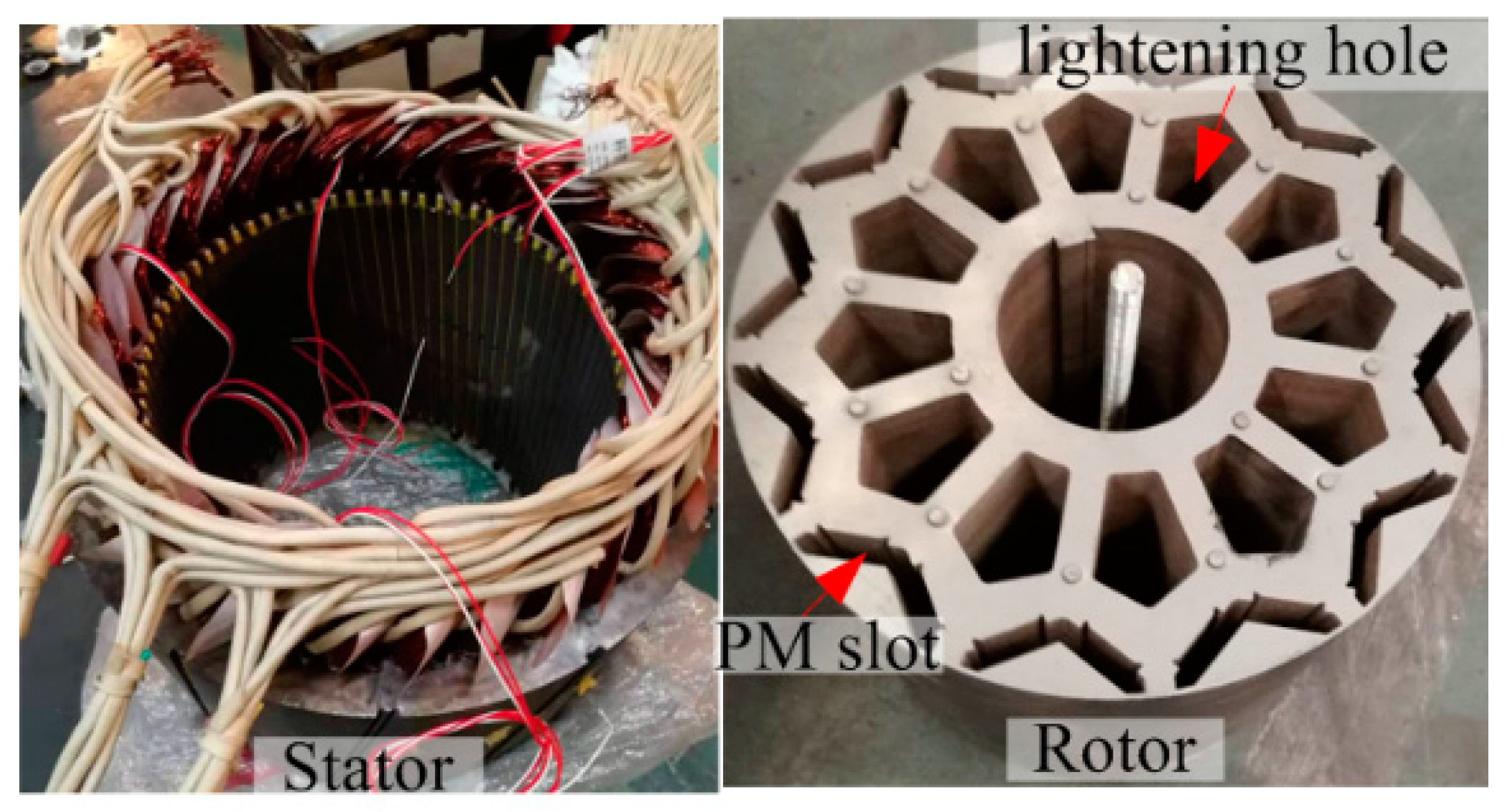
2. Machine Topology and Finite Element Model

The research object of this paper is a 130 kW, 1500 rpm IPMSM. The FEA model of the IPMSM and design specifications are given in Figure 1 and Table 1, respectively. The transient mathematical model of two-dimensional electromagnetic field calculation is presented in Equation (1). In the FEA model, the IPMSM machine is supplied by a current source [25].
{ Ω :   x ( 1 μ A z x ) + y ( 1 μ A z y ) σ A z t = J z Γ 1 : A z = 0 Γ 2 : 1 μ 1 A z n 1 μ 2 A z n = J s
where Ω is the calculation region, Az and Jz represent the magnetic vector potential and the source current density in the z-axial component respectively (in A/m2), Js is the equivalent face current density of the permanent magnet (in A/m2), and σ is the conductivity (in S/m). Γ1 indicates the parallel boundary conditions, Γ2 indicates the PM boundary condition, and μ1 and μ2 represent the relative permeability. Equation (1) presents the calculation basics of the IPMSM and indicates that the electromagnetic performances are directly related to the part of machine topology which is located near the airgap. Thus, more attention is paid to the rotor surface arc.
In order to simplify the calculation and analysis, it is assumed that [26]:
  • A displacement current and the skin effect in the stator windings are ignored.
  • Materials are isotropic. Permeability and conductivity of the materials are constant except the stator core and the rotor yoke.
  • The displacement current is ignored.

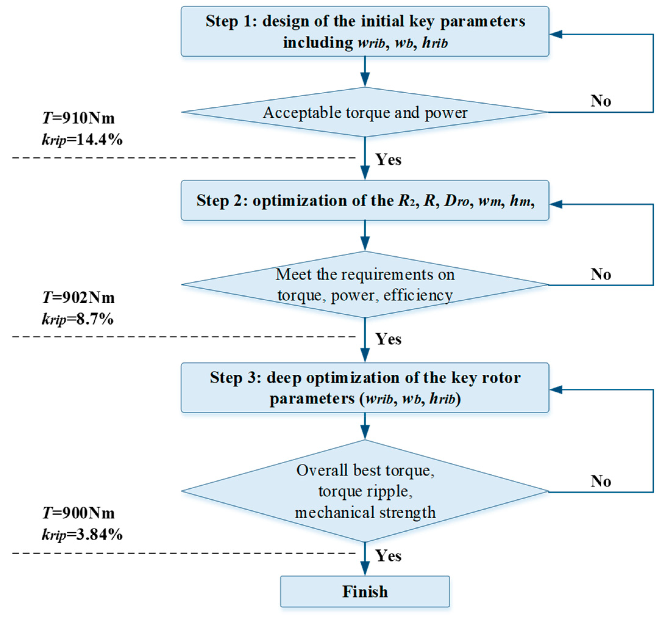
3. Optimization, Considering the Cogging Torque and Torque Ripple

The cogging torque is the torque generated by the interaction between the iron core and the magnet when current is not applied. For a heavy-load machine, the cogging torque mainly degrades the performance at low speed and high torque. In this paper, the variations of cogging torque and output electromagnetic torque under different conditions were studied by optimizing the shape of the rotor surface core, the topology of the rotor PM, and the shape of the iron bridge. The variation of cogging torque and output electromagnetic torque under different conditions are studied.
First of all, the electromagnetic torque Tθ(t) at any time t can be calculated by integrating the tangential stress σ (θ, t), on the rotor over the surface [27],
( θ , t ) = B c ( θ , t ) B r ( θ , t ) μ 0
T θ ( t ) = r 2 μ 0 0 l a 0 2 π B c ( θ , t ) B r ( θ , t ) d θ d t
where Bc(θ, t) and Br(θ, t) are the circumferential and radial flux density components around the air-gap circumference; la is the stack length; r is the rotor outer radius. And Bc,r(θ, t) is obtained by,
B c , r ( θ , t ) = 1 μ 0   F ( θ , t ) δ ( θ , t )
where F(θ, t) is the distributed magneto-motive-force, and δ(θ, t) is the effective air-gap length, which is related to the slots of the stator.
Equations (2)–(4) indicate that the cogging torque and electromagnetic torque are calculated based on the flux density distributions in the air-gap, which are directly related to the shape of the rotor pole surface. Thus, the air-gap flux density distributions and rotor pole surface arc were studied, as follows.

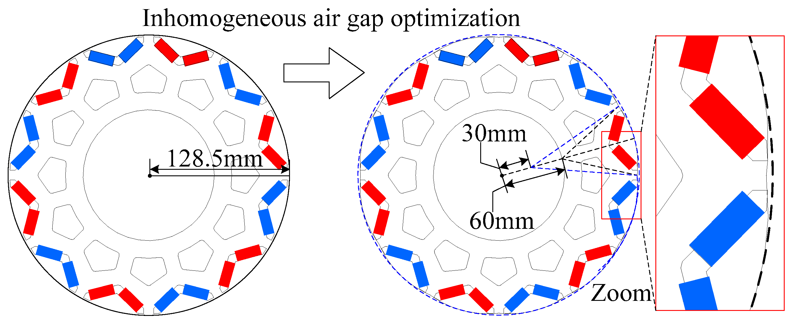
3.1. The Optimization of the Rotor Iron Core by Adopting a Rotor Pole Arc Offset

3.1.1. Air-Gap Flux Density Distributions

First of all, the electromagnetic torque, torque fluctuation, electromagnetic vibration, and noise is directly related to the air-gap flux density distributions. Reducing the harmonic content in air-gap flux density can effectively weaken cogging torque and torque ripple. Because the excitation magnetic field of the PMSM is sinusoidal when the air-gap magnetic field waveform is close to the sinusoidal waveform, the cogging torque and torque ripple of the PMSM can be effectively reduced, and the control accuracy of the PMSM can be improved. By streamlining the core of the rotor surface, the shape of the air-gap magnetic field can be optimized. The rotor surface arc offset was employed, as illustrated in Figure 2, where R is the offset distance; i.e., the distance of the rotor pole arc center from the rotor center. The conditions from 0 to 50 mm were analyzed. As a result, the air-gap length became uneven along the rotor surface. The degree of said unevenness grew with the increase of R. Figure 3 shows the 2-D FEA calculated air-gap flux density distributions and the corresponding harmonic contents. After the eccentric design, the air-gap magnetic field was more sinusoidal. With the increase of the offset distance of the rotor outer surface, the amplitude of the air-gap magnetic density fundamental current increased gradually, while the other harmonic components decreased. The distortion rate of the air-gap magnetic field decreased after the eccentricity of the rotor outer circle increased. Under the traditional conditions, without rotor surface offset, the amplitude of the air-gap magnetic density fundamental wave is 0.97 T, which can be increased by 13.4% when the offset distance is 40 mm.

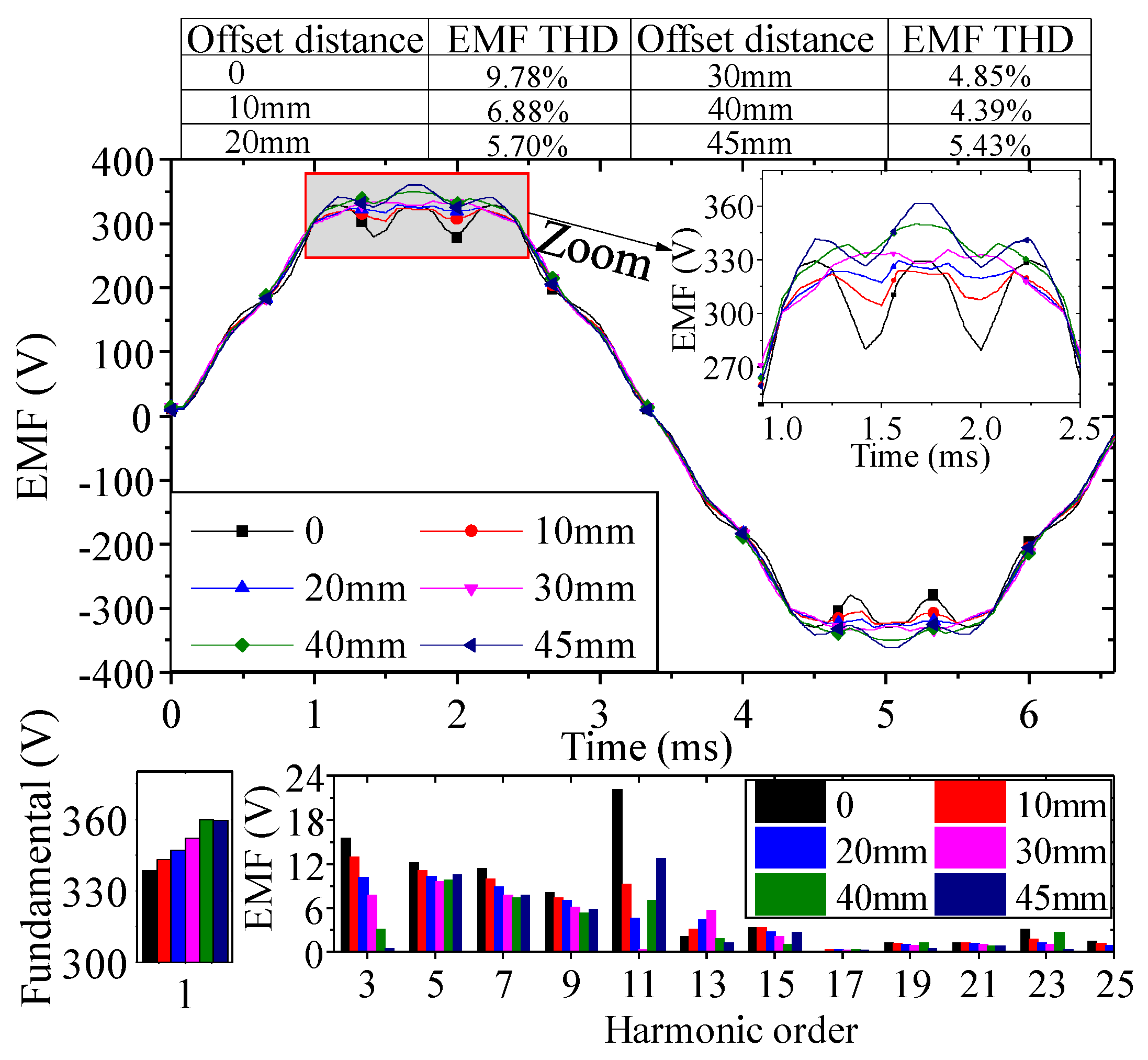
3.1.2. Back Electro-Motive-Force Waveforms

The variation of the EMF waveform and harmonic content with different rotor core shapes is given in Figure 4, where the total harmonic distort (THD) is calculated by,
THD = i = 2 B g i 2 B g 1 × 100 ( % )
As can be seen, the back-EMF waveforms tend to be more sinusoidal with the increase of offset distance, and the harmonics of higher order are weakened, especially the 11th order one. It should be noted that the fundamental back-EMF is 359.8 V when the offset distance is 40 mm, which is 8.4% greater than the condition of non-eccentric; i.e., 332 V. Since the fundamental content of air-gap flux density increases with offset distance, it consequently results in a greater back-EMF.

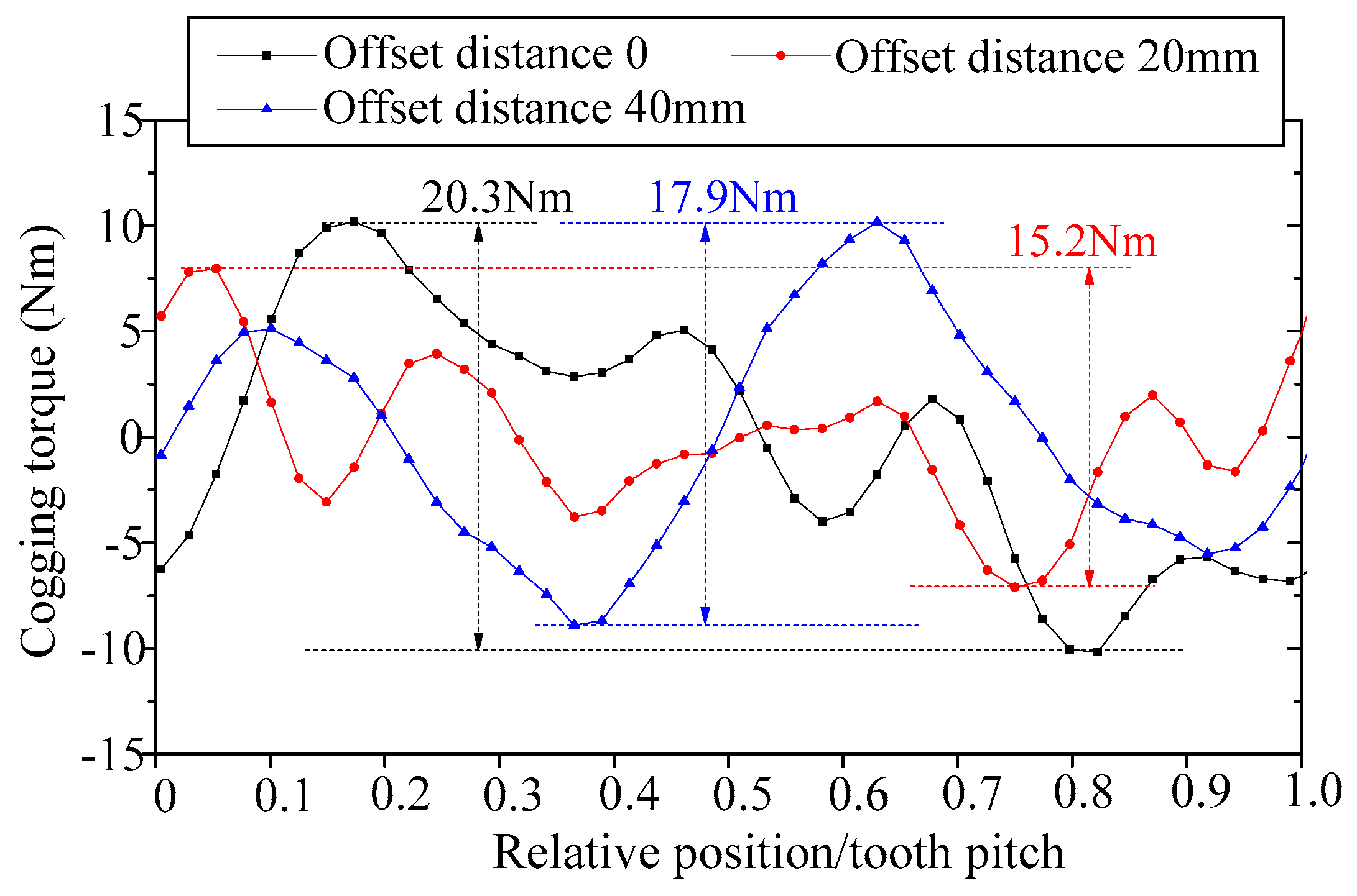
3.1.3. Cogging Torque and Torque Ripple

The cogging torque and the electromagnetic torque under different eccentricities are shown in Figure 5, Figure 6 and Figure 7. The peak value of cogging torque was 20.3 Nm when the offset distance was 0, which is 2.4% of the rated output torque. Peak values were 15.2 Nm and 17.9 Nm when the offset distances were 20 mm and 40 mm, respectively, which is 11.8% and 25.1% lower than that when the offset distance was 0. When the air-gap was uniform, the average value of output electromagnetic torque is 912.4 Nm, the peak value of torque fluctuation was 176.7 Nm, and the fluctuation coefficient was 13.8%. Employing an eccentric rotor pole arc would reduce the cogging torque; however, the average torque output would also be reduced with the increase of the offset distance. As can be found in Figure 6, when the offset distance was 40 mm, the average output electromagnetic torque decreased to 876.5 Nm, which is 3.9% lower than the case of non-offset, and the torque ripple was 74.8 Nm, which is 57.7% lower than the case of non-offset.
Figure 7 shows the comprehensive comparison of the cogging torque, average torque and torque ripple under different eccentricities. Firstly, the cogging torque varied nonlinearly with offset distance. The cogging torque achieved its greatest and smallest values, i.e., 33.4 Nm and 6.33 Nm, when the offset distances were 5 mm and 15 mm, respectively. Secondly, the average torque output decreased with the increase of offset distance; and the average torque achieved the lowest value when the offset distance was 40 mm. In the next part, the topology of the permanent magnets and the iron bridge were optimized to minimize the torque ripple.

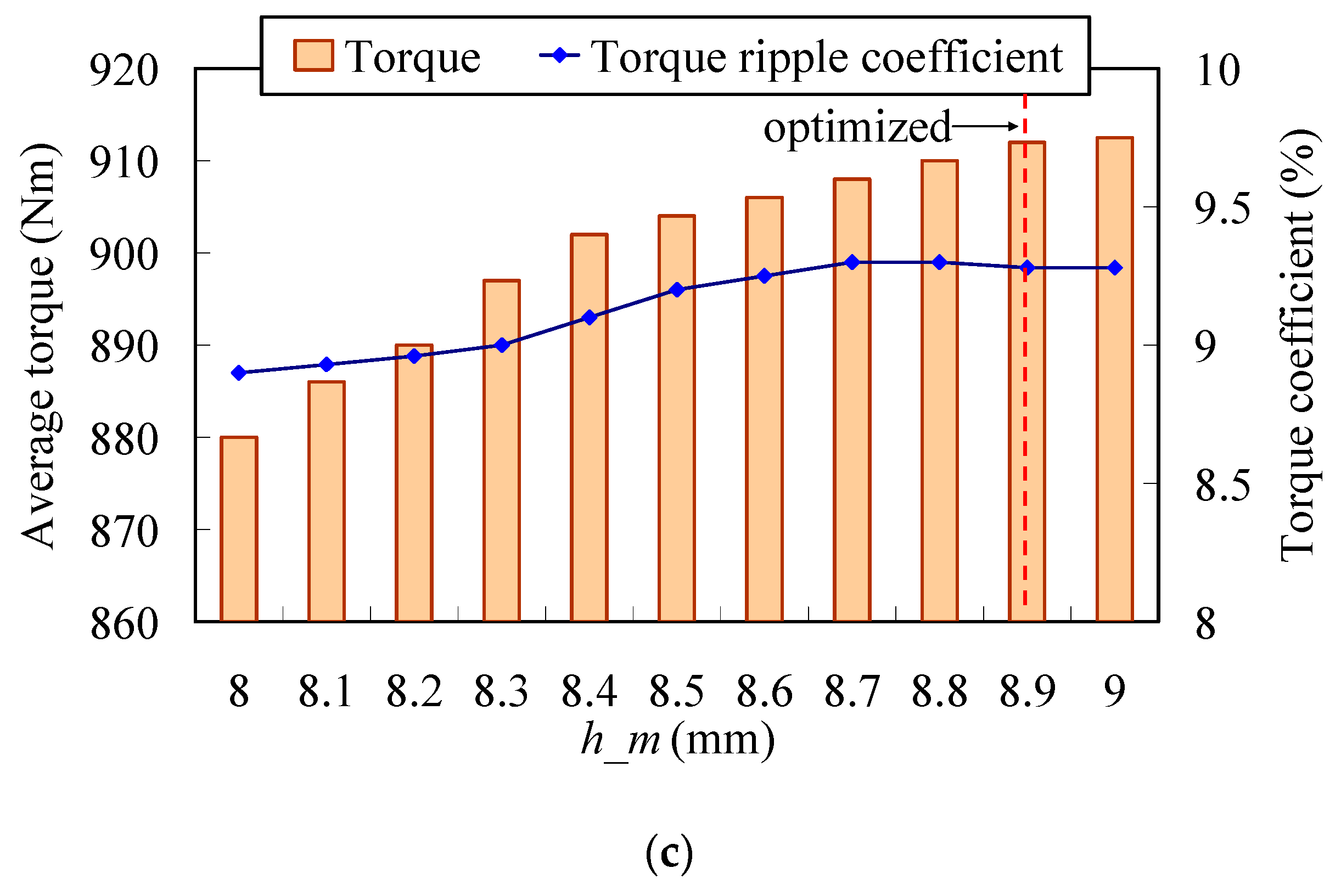
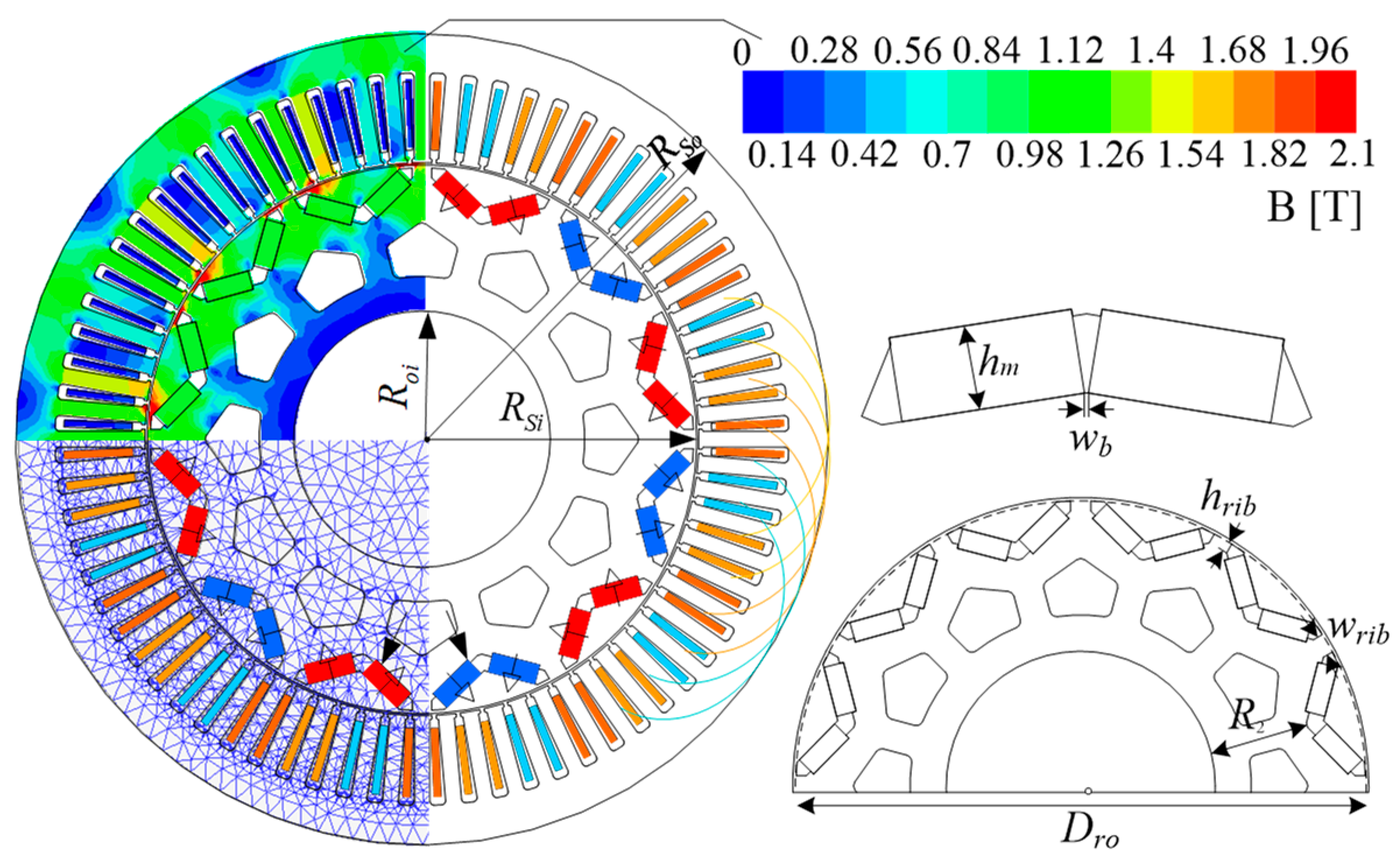
3.2. Optimization of Permanent Magnet and Iron Bridge

The topology and location of permanent magnets and the iron bridges are also critical to the electric performances, especially for the torque output performances. First of all, several key parameters of the rotor PM are studied below. The key parameters of the rotor PM are R2, wrib, hrib, and wb, as can be found in Figure 1. The wb and hrib are directly related to the permanent magnet flux leakages, while wrib and R2 show more influences on q-axis inductances, thus torque output capabilities. The torque performances were obtained by 2-D FEA, as shown in Figure 8, where the torque ripple coefficient krip is defined as
k r i p = t o r q u e   r i p p l e a v e r a g e   t o r q u e
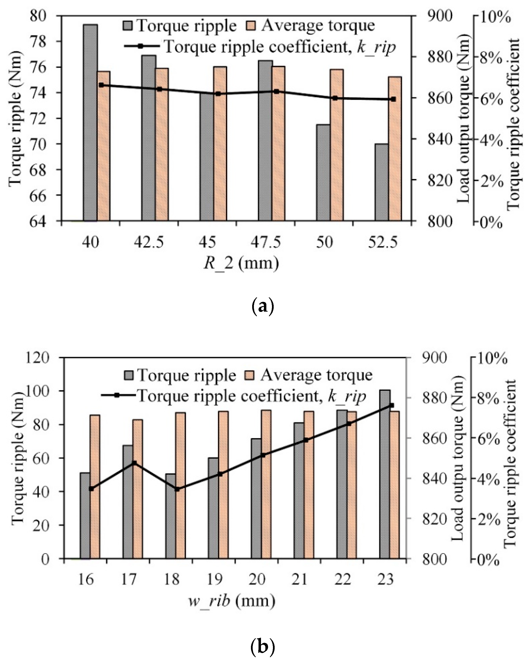
  • As shown in Figure 8a, the average torque changed slightly with the variation of R2. Thus, the influence of R2 on the torque output capabilities was negligible. However, the torque ripples and thus krip varied greatly with R2. When R2 was 52.5 mm, the output torque ripple was the smallest and tended to be stable, with a value of 70 Nm and a krip of 5.8%, which is acceptable in heavy-load traction vehicles.
  • As shown in Figure 8b, the output torque was almost unchanged with the increase of distance between the poles, i.e., wrib, because the back-EMF and inductances remained unchanged. As for the torque ripple, it achieved the peak value of 51.2 Nm and krip of 7.9% when wrib was 16 mm, and exhibited a nonlinear trend with the variation of wrib. The lowest krip was 4.18% when wrib was 18 mm, which is much lower than the case of 16 mm. This can be explained, as when the wrib is changed, the pole arc coefficient and the air-gap magnetic field harmonic content changes significantly.
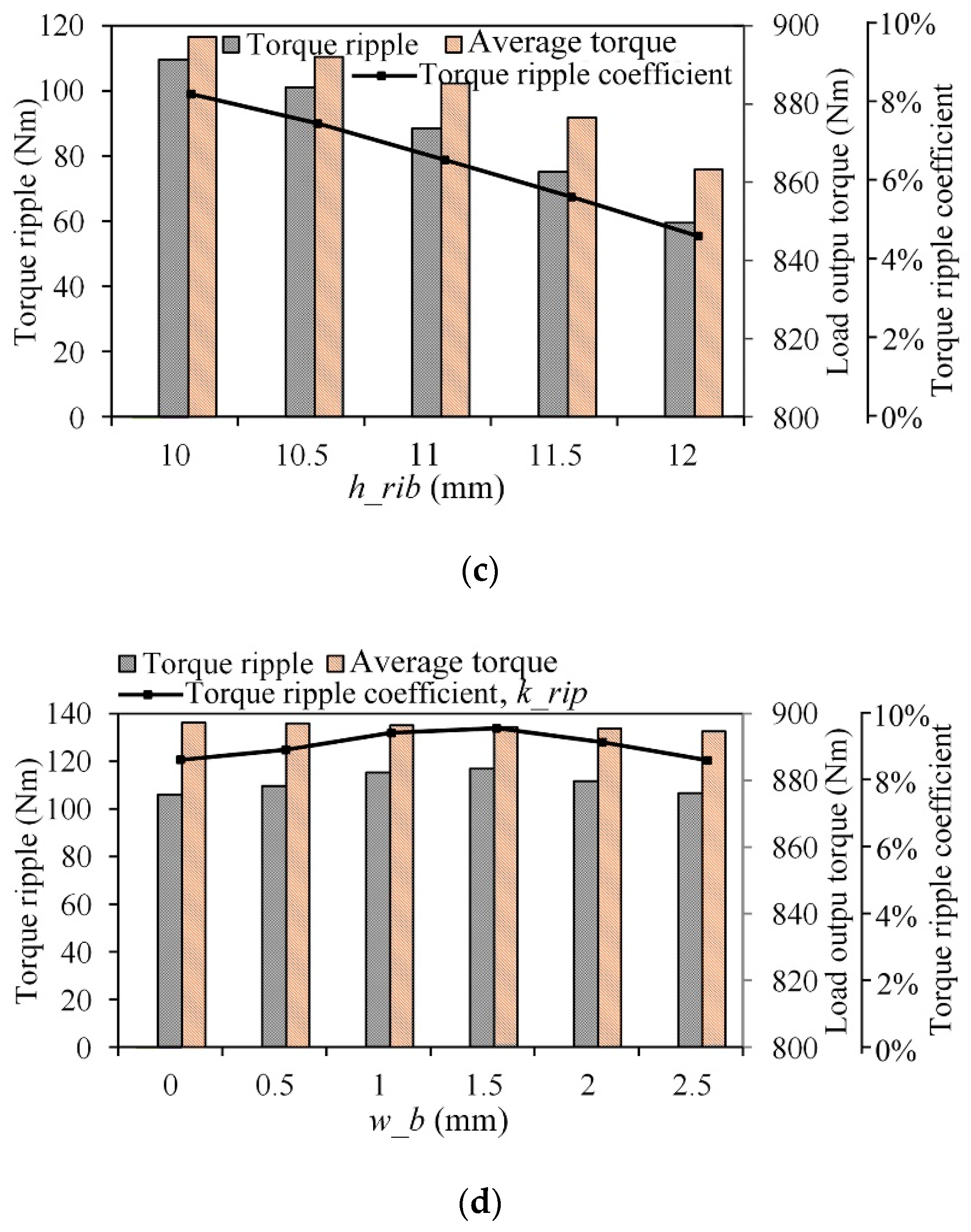
  • As shown in Figure 8c, both the output torque and torque ripple reduced linearly with the increase of hrib; an apparent variation was found in the torque ripple especially. The average output torque was 897.1 Nm and the krip wass 8.78% when hrib was 10 mm; meanwhile, they were 863.2 Nm and 3.8% respectively, when hrib was 12 mm. Comparing those two cases, it was found that with the cost of 3.8% reduced torque output, the krip could be reduced by 45.6%.
  • Figure 8d shows that wb had a negligible influence on torque ripples, since it mainly provides necessary mechanical strength, and will enlarge the permanent magnet leakage fluxes, and should be designed as small as possible.

3.3. The Comprehensive Optimization of the Rotor’s Key Paramenters

3.3.1. The Three Key Rotor Parameters

The above analysis gives the relationship between the key parameters in the rotor with the torque performances, respectively. In this part, Figure 9 shows the variation of torque performances considering the wrib, hrib, and wb comprehensively, when R2 was 47.5 mm. As shown in Figure 9a, the average torque varied from 858.7 Nm to 894 Nm when the hrib changed; and hrib showed greater influence on torque output than the other two parameters. It can be clearly seen from Figure 9b that when the wrib changed, the torque ripple varied from 64.6 Nm to 123.8 Nm. The torque ripple coefficient krip could be considered more sensitive to wrib than to hrib and wb. Overall, Figure 9 provides a reference for optimizing the design of IPMSM with V-type magnets. If the torque ripple is taken as the optimization objective, the minimum torque ripple is 46.4 Nm with a torque ripple coefficient of 3.84%, and the torque waveforms are compared by Figure 10. Table 2 summarizes the influences of the key parameters on the average torque and torque ripple. Table 2 shows the optimization priority of the three key parameters: hrib should be optimized firstly to get high torque output capability; then wrib is optimized aiming at low torque ripple; finally, wb is optimized to get overall better torque output and lower torque ripple.

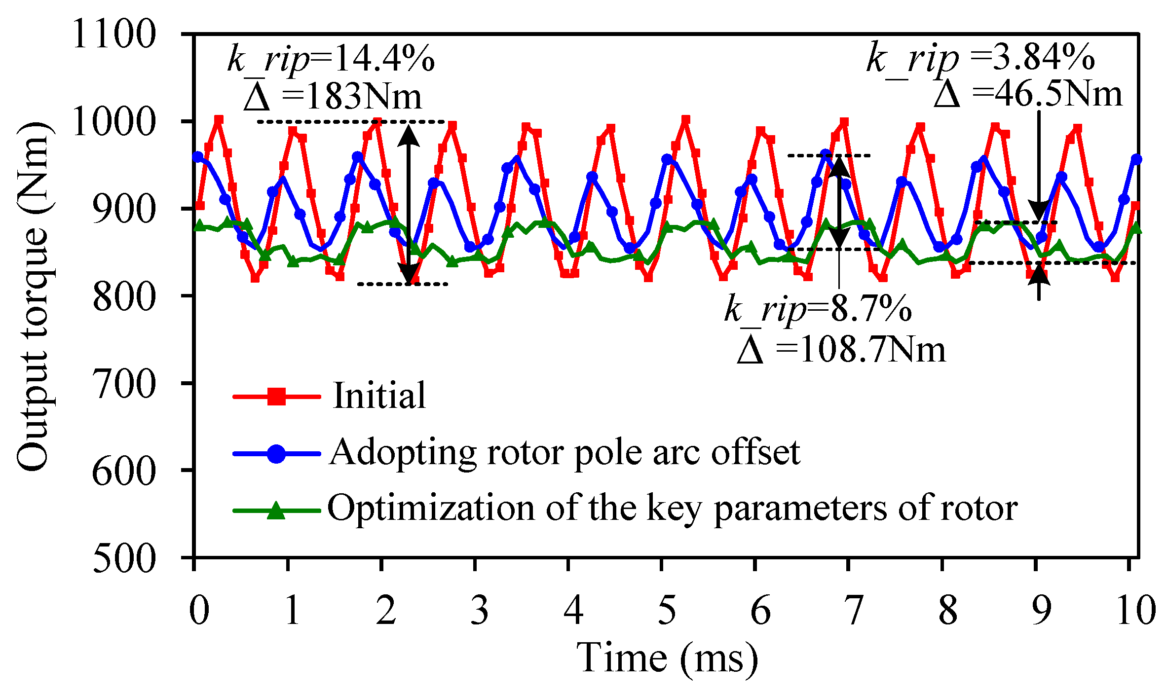
3.3.2. Torque Performances of the Final Machine

Figure 10 shows the design and optimization process of the IPM motor, which is divided into three steps: Firstly, the initial key motor parameters including the wrib, wb, and hrib were obtained in step 1, aiming at acceptable torque and power that were close to the requirements. The torque and torque ripple were 910 Nm and 14.4% when step 1 was finished. Secondly, the rotor pole surface offset was employed, and optimized along with the split ratio (obtained by Dro/Dso), wm, hm, and R2 by multi-objective genetic algorithm carried out on JMAG. Figure 11 shows the influences of the Dro, wm, hm on the torque performances. The optimized torque was 902 Nm, which was lower than the result in step 1, since the efficiency was considered in step 2. Meanwhile the torque ripple was reduced to 8.7%. Finally, the deep optimizations of the three key rotor parameters, wrib, wb, and hrib were carried out, aiming at low torque ripple and high mechanical strength. Figure 12 compares the torque output performances due to different optimization methods mentioned in the previous section. Table 3 shows the comparison of the initial and final parameters. The average torque, torque ripple, and krip of the original machine before optimization was 910 Nm, 183 Nm, and 14.4%, respectively. When the eccentric rotor pole arc was employed, the average torque and torque ripple was 902 Nm and 8.77%, respectively. Then the rotor key parameters were furthermore optimized based on the eccentric rotor pole model. Finally, after a comprehensive optimization of the rotor topology and parameters, the torque ripple was reduced to 46.5 Nm with krip = 3.84%, which was much better than the original model, at the cost of a slight drop in average torque output.

3.3.3. Brief Discussion on Different Optimization Methods

Here, the output torque ripple optimization method and results are compared with other methods mentioned in the references, as shown in Table 4.
  • Reference [3] analyzes an IPMSM machine which has a similar V-type magnets topology with the machine in this paper, but a slightly different pole-slot fit. Reference [9] optimizes an IPMSM machine by using asymmetric rotor topology. Overall, the torque ripple is larger than the that obtained in this paper.
  • References [5,7,8] present the optimization of IPMSM machines with I-type magnet location. As can be seen, the torque ripples can be significantly reduced after the optimization, which, however, are still larger than that present in this paper, except for the machine in [7]. It should be emphasized that the complex hybrid Ferrite and rear-earth permanent magnets are employed in [7] to reduce the torque ripple, which, meantime, will cause greater machine cost and much more manufacturing difficulties, and consequently degrade its potential in industrial applications.

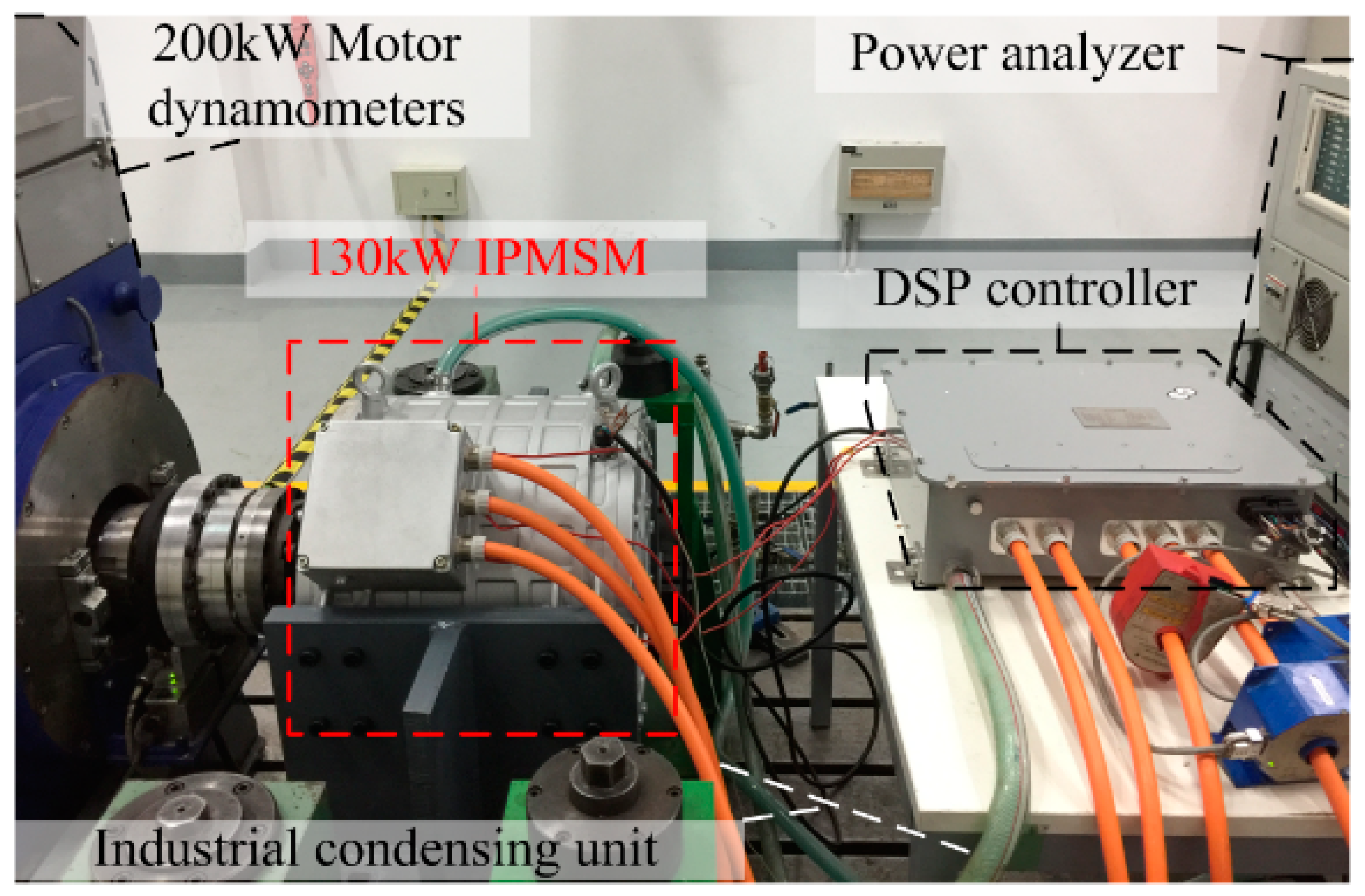
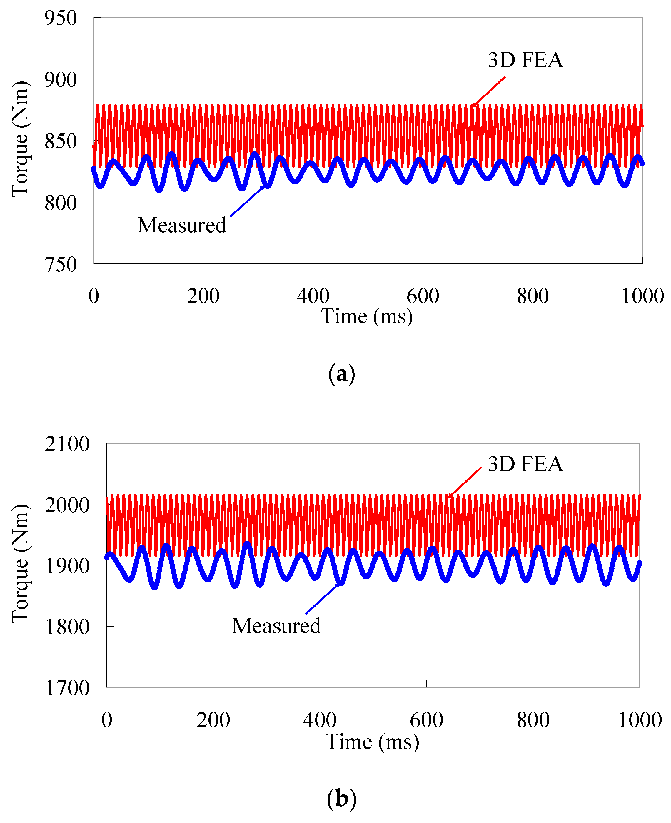
4. Experimental Validations

In order to verify the FEA results, a prototype of the proposed machine after optimization was manufactured, as shown in Figure 13. The holes were adopted on the rotor iron to reduce the weight and inertia. Figure 14 shows the testing platform, which contained the 200 kW dynamometer machine to provide the electromagnetic load, a YOKOGAWA power analyzer, an industrial condensing unit, DSP controller, etc. Water cooling was also employed.
Figure 15 and Table 3 compares the FEA calculated and measured torque results which were obtained at the rated operation (235 A) and peak torque output operation (540 A), respectively. It should be emphasized that the calculated and measured waveforms exhibited different torque ripple frequencies due to the relatively high sample time of the torque transducer, and the measured torque ripples were smaller than the calculated results. Overall, satisfying agreement was achieved between FEA results and experimental measurements, with the discrepancies of near 4%, considering the manufacturing and measuring tolerances. Figure 16 shows the FEA calculated and measured efficiency map. The efficiency was measured to cover the whole torque-speed region when the DC bus voltage was 540 V. The iron loss and copper loss were counted in the FEA calculations, which were carried out when the temperature was 80 °C, while in the experimental measurements, the iron loss, copper loss, and mechanic loss were counted in, and the measured temperature in stator was near 80 °C when the cooling water was 20 °C. As can be seen, good agreement was achieved. It was found that nearly 80% of the total operation region had an efficiency above 90%, and 45% of the total operation region had an efficiency above 95%.

5. Discussions

It should be emphasized that the average torque is also very important to a heavy-load traction vehicle, although this paper is mainly focused on the optimization of cogging torque and torque ripples. Since the torque ripple may cause big problems to the start and brake performance of a traction vehicle, which is worse with heavy loads. We suggest that the study on the skewed stator slots can be carried out in the future work, since it has great potential to reduce the cogging torque and torque ripple, and is more practical to be manufactured than the skewed rotor for an IPMSM. Nevertheless, the optimization of average torque and efficiency should also be carried out in future work, as should the analysis of the mechanic behaviors.

6. Conclusions

In this paper, a 130 kW 12-pole/72-slot internal permanent magnet synchronous machine (IPMSM) was designed for heavy-load traction vehicles applied in port transportation. More attention was paid to the optimization of cogging torque and torque ripple, since they generate vibrations and radial electromagnetic force fluctuations, and degrade the start and brake performances of the vehicle, which are critical to port transportation. By adopting the eccentric rotor pole arc and the comprehensive optimization of the key parameters of the rotor iron and permanent magnets, the cogging torque can be reduced from 14.4% to 3.84%, which meets the requirement of a traction vehicle. The optimization method in this paper is also compared with other methods mentioned in the references. Finally, the machine prototype was manufactured and tested on a platform with water cooling. The torque performances and efficiency map are given. Overall, satisfying agreement was achieved between the FEA results and experimental measurements.

Author Contributions

Conceptualization, G.Z.; data curation, W.Y. and A.G.; formal analysis, G.Z. and W.Y.; funding acquisition, R.C.; investigation, W.Y., Wei Hua, H.Q., and A.G.; methodology, G.Z., W.Y., and W.H.; supervision, G.Z. and R.C.; writing—original draft, G.Z.

Funding

This research was funded in part by the Fundamental Research Funds for the Central Universities, grant number NJ2018004, in part by the National Laboratory of China, grant number ACSKL2018KT08, in part by the National Key R&D Plan Project, grant number 2017YFB1300902, in part by the CALT, grant number 201806, and in part by Youth Science and Technology Talents Development Project of Guizhou Education Department, grant number [2018]393.

Conflicts of Interest

The authors declare no conflict of interest.

References

  1. Feng, S.; Jiang, W.; Zhang, Z.; Zhang, J.; Li, Y.; Wang, Y. Study of efficiency characteristics of Interior Permanent Magnet Synchronous Motors. IEEE Trans. Magn. 2018, 54, 1–5. [Google Scholar]
  2. Shanshal, A.; Hoang, K.; Atallah, K. High-Performance Ferrite Permanent Magnet Brushless Machines. IEEE Trans. Magn. 2017, 55, 8104504. [Google Scholar] [CrossRef]
  3. Wu, S.N.; Tang, R.Y.; Tong, W.M.; Han, X.Y. Analytical Model for Predicting Vibration Due to Magnetostriction in Axial Flux Permanent Magnet Machines with Amorphous Metal Cores. IEEE Trans. Magn. 2017, 53, 2001508. [Google Scholar] [CrossRef]
  4. Li, J.; Xu, Y.; Zou, J.; Wang, Q.; Liang, W. Analysis and Reduction of Magnet Loss by Deepening Magnets in Interior Permanent Magnet Machines with a Pole/Slot Ratio of 2/3. IEEE Trans. Magn. 2015, 51, 1–4. [Google Scholar] [CrossRef]
  5. Tiegna, H.; Amara, Y.; Barakat, G. Study of Cogging Torque in Axial Flux Permanent Magnet Machines Using an Analytical Model. IEEE Trans. Magn. 2014, 50, 845–848. [Google Scholar] [CrossRef]
  6. Ren, W.; Xu, Q.; Li, Q. Asymmetrical V-Shape Rotor Configuration of an Interior Permanent Magnet Machine for Improving Torque Characteristics. IEEE Trans. Magn. 2015, 51, 1–4. [Google Scholar] [CrossRef]
  7. Zhu, S.; Chen, W.; Xie, M.; Liu, C.; Wang, K. Electromagnetic Performance Comparison of Multi-Layered Interior Permanent Magnet Machines for EV Traction Applications. IEEE Trans. Magn. 2018, 54, 1–5. [Google Scholar] [CrossRef]
  8. Bozhko, S.; Rashed, M.; Hill, C.I.; Yeoh, S.S.; Yang, T. Flux-Weakening Control of Electric Starter–Generator Based on Permanent-Magnet Machine. IEEE Trans. Transp. Electrif. 2017, 3, 864–877. [Google Scholar] [CrossRef]
  9. Wang, A.; Jia, Y.; Soong, W.L. Comparison of Five Topologies for an Interior Permanent-Magnet Machine for a Hybrid Electric Vehicle. IEEE Trans. Magn. 2011, 47, 3606–3609. [Google Scholar] [CrossRef]
  10. Dajaku, G.; Hofmann, H.; Hetemi, F.; Dajaku, X.; Xie, W.; Gerling, D. Comparison of Two Different IPM Traction Machines With Concentrated Winding. IEEE Trans. Ind. Electron. 2016, 63, 4137–4149. [Google Scholar] [CrossRef]
  11. Valente, G.; Papini, L.; Formentini, A.; Gerada, C.; Zanchetta, P. Radial Force Control of Multisector Permanent-Magnet Machines for Vibration Suppression. IEEE Trans. Ind. Electron. 2018, 65, 5395–5405. [Google Scholar] [CrossRef]
  12. Lan, H.; Zou, J.; Xu, Y.; Liu, M. Investigation of Unbalanced Magnetic Force in Permanent Magnet Synchronous Machines With Asymmetric Design. IEEE Trans. Magn. 2018, 54, 1–5. [Google Scholar] [CrossRef]
  13. Pop, C.V.; Birte, O.; Fodorean, D. Noise and Vibrations Analysis of a Permanent Magnet Synchronous Machine for Light Electric Vehicle. In Proceedings of the 52nd International Universities Power Engineering Conference (UPEC), Heraklion, Greece, 28–1 August 2017; p. 17451257. [Google Scholar]
  14. Jin, L.; Wang, F.; Yang, Q. Performance Analysis and Optimization of Permanent Magnet Synchronous Motor Based On Deep Learning. In Proceedings of the 20th International Conference on Electrical Machines and Systems (ICEMS), Sydney, Australia, 11–14 August 2017; pp. 1–5. [Google Scholar]
  15. Han, S.H.; Jahns, T.M.; Soong, W.L.; Güven, M.K.; Illindala, M.S. Torque Ripple Reduction in Interior Permanent Magnet Synchronous Machines Using Stators With Odd Number of Slots Per Pole Pair. IEEE Trans. Energy Convers. 2010, 25, 118–127. [Google Scholar] [CrossRef]
  16. Takahashi, N.; Yamada, T.; Shimose, S.; Miyagi, D. Optimization of Rotor of Actual IPM Motor Using ON/OFF Method. IEEE Trans. Magn. 2011, 47, 1262–1265. [Google Scholar] [CrossRef]
  17. Lim, S.; Min, S.; Hong, J.P. Low Torque Ripple Rotor Design of the Interior Permanent Magnet Motor Using the Multi-Phase Level-Set and Phase-Field Concept. IEEE Trans. Magn. 2012, 48, 907–910. [Google Scholar] [CrossRef]
  18. Sizov, G.Y.; Zhang, P.; Ionel, D.M.; Demerdash, N.A.O.; Rosu, M. Automated Multi-Objective Design Optimization of PM AC Machines Using Computationally Efficient FEA and Differential Evolution. IEEE Trans. Ind. Appl. 2013, 49, 2086–2096. [Google Scholar] [CrossRef]
  19. Ren, W.; Xu, Q.; Li, Q.; Zhou, L. Reduction of Cogging Torque and Torque Ripple in Interior PM Machines with Asymmetrical V-Type Rotor Design. IEEE Trans. Magn. 2016, 52, 1–5. [Google Scholar] [CrossRef]
  20. Feng, G.; Lai, C.; Kar, N.C. Practical Testing Solutions to Optimal Stator Harmonic Current Design for PMSM Torque Ripple Minimization Using Speed Harmonics. IEEE Trans. Power Electron. 2018, 33, 5181–5191. [Google Scholar] [CrossRef]
  21. Navardi, M.J.; Milimonfared, J.; Talebi, H.A. Torque and Flux Ripples Minimization of Permanent Magnet Synchronous Motor by a Predictive-Based Hybrid Direct Torque Control. IEEE J. Emerg. Sel. Top. Power Electron. 2018, 6, 1662–1670. [Google Scholar] [CrossRef]
  22. Choi, Y.S.; Choi, H.H.; Jung, J.W. Feedback Linearization Direct Torque Control with Reduced Torque and Flux Ripples for IPMSM Drives. IEEE Trans. Power Electron. 2016, 31, 3728–3737. [Google Scholar] [CrossRef]
  23. Liu, Q.; Hameyer, K. Torque ripple minimization for direct torque control of PMSM with modified FCSMPC. IEEE Trans. Ind. Appl. 2016, 52, 4855–4864. [Google Scholar] [CrossRef]
  24. Ren, Y.; Zhu, Z.Q. Reduction of Both Harmonic Current and Torque Ripple for Dual Three-Phase Permanent-Magnet Synchronous Machine Using Modified Switching-Table-Based Direct Torque Control. IEEE Trans. Ind. Electron. 2015, 62, 6671–6683. [Google Scholar] [CrossRef]
  25. Li, W.L.; Wang, J.; Zhang, X.C.; Kou, B.Q. Loss Calculation and Thermal Simulation Analysis of High-Speed PM Synchronous Generators with Rotor Topology. In Proceedings of the International Conference on Computer Application and System Modeling (ICCASM), Taiyuan, China, 22–24 October 2010; Volume 14, pp. 612–616. [Google Scholar]
  26. Qiu, H.; Yu, W.; Tang, B.; Li, W.; Yang, C.; Wang, Y. Effects of driving modes on permanent magnet motor electromagnetic and temperature fields at limit conditions. COMPEL Int. J. Comput. Math. Electr. Electron. Eng. 2016, 35, 2045–2062. [Google Scholar] [CrossRef]
  27. Spargo, C.M.; Mecrow, B.C.; Widmer, J.D. A Seminumerical Finite-Element Postprocessing Torque Ripple Analysis Technique for Synchronous Electric Machines Utilizing the Air-Gap Maxwell Stress Tensor. IEEE Trans. Magn. 2014, 50, 1–9. [Google Scholar] [CrossRef]
Figure 1. Finite element model of the 12-pole/72-slot internal permanent magnet synchronous machine (IPMSM).
Applsci 09 03634 g001
Figure 2. Illustration of the rotor pole arc offset.
Applsci 09 03634 g002
Figure 3. Comparisons of influence based on finite element analysis (FEA) results for rotors parameterized with various arc offsets.
Applsci 09 03634 g003
Figure 4. The influence of rotor surface arc offset distance on back electro-motive-force.
Applsci 09 03634 g004
Figure 5. Influence of different rotor pole arc offset distance on the cogging torque.
Applsci 09 03634 g005
Figure 6. Influence of different rotor pole arc offset distance on torque ripple at rated operation.
Applsci 09 03634 g006
Figure 7. The variation of cogging torque and output torque with the rotor pole arc offset distance.
Applsci 09 03634 g007
Figure 8. Then-influences of magnet position on average torque and torque ripple. (a) Influence of R2; (b) influence of wrib; (c) influence of hrib; (d) influence of wb.
Applsci 09 03634 g008aApplsci 09 03634 g008b
Figure 9. Analysis of key factors affecting output torque. (a) Output torque. (b) Torque ripple.
Applsci 09 03634 g009
Figure 10. Demonstration of the design and optimization process.
Applsci 09 03634 g010
Figure 11. Influences of the Dro, wm, and hm on the torque performances. (a) Influences of the rotor’s outer diameter, Dro. (b) Influences of the magnet width wm. (c) Influences of the magnet height hm.
Applsci 09 03634 g011aApplsci 09 03634 g011b
Figure 12. Comparison of the torque performances when 250 Arms is applied.
Applsci 09 03634 g012
Figure 13. The stator and rotor of the IMPSM prototype.
Applsci 09 03634 g013
Figure 14. Experimental platform and instruments.
Applsci 09 03634 g014
Figure 15. Comparison of the FEA calculated and measured torque output. (a) Rated operation when 235 A is applied. (b) Peak torque output operation when 540 A is applied.
Applsci 09 03634 g015
Figure 16. Comparison of the FEA calculated and measured efficiency map. (a) FEA calculated; (b) Measured results.
Applsci 09 03634 g016
Table 1. Key design specifications and parameters of the IPMSM.
Main SpecificationsValueKey ParametersValue
Rated power output 130 kWNumber of poles12
Rated speed1500 r/minNumber of slots72
DC bus voltage540 VStator outer diameter190 mm
Rated current235 AStator inner diameter 129.5 mm
Winding connection mode YCore length240 mm
Number of phases3PM width 9 mm
Rate torque output 830 NmPM length per pole45 mm
Table 2. The influence of the three key parameters on torque performances.
Itemhribwribwb
Average torqueHigh influencemediummedium
Torque ripplemediumHigh influencemedium
Table 3. Comparison of initial and final optimized key rotor parameters.
ParameterInitialOptimizedObtained
Dro240 mm254 mmin step 2 of the design process
R245 mm64.5 mm
hm8.2 mm8.9 mm
wm48 mm45.2 mm
wb2 mm3.2 mmin step 3 of the design process
hrib11 mm4.5 mm
wrib18 mm9 mm
Table 4. Comparison of optimization methods presented in references.
Machine TypeOptimization MethodTorque Ripple (%)
OriginalOptimized
V-type IPMSM
(this paper)
Rotor topology183 Nm (14.4%)46.4 Nm (3.84%)
V-type IPMSM [15]Pole and slot matching61 Nm (8.2%)29.2 Nm (4.6%)
V-type IPMSM [19]Asymmetrical rotor1.29 Nm (12.5%)0.44 Nm (4.38%)
I-type IPMSM [16]Rotor topology2.15 Nm (12.55%)2.04 Nm (6.95%)
I-type IPMSM [17]Rotor topology44.6 Nm (56.2%)26.3 Nm (2.8%)
I-type IPMSM [18]Computationally efficient FEA1.61 Nm (10.6%)1.02 Nm (4.9%)

