Article

Operational Optimisation of a Non-Recuperative 1-kWe Organic Rankine Cycle Engine Prototype

1
Clean Energy Processes (CEP) Laboratory, Department of Chemical Engineering, Imperial College London, London SW7 2AZ, UK
2
State Key Laboratory of Engines, Tianjin University, Tianjin 300072, China
*
Author to whom correspondence should be addressed.
Appl. Sci. 2019, 9(15), 3024; https://doi.org/10.3390/app9153024
Submission received: 4 June 2019 / Revised: 12 July 2019 / Accepted: 17 July 2019 / Published: 26 July 2019
(This article belongs to the Special Issue Organic Rankine Cycle Systems for Waste-Heat Recovery)

Abstract

:
Several heat-to-power conversion technologies are being proposed as suitable for waste-heat recovery (WHR) applications, including thermoelectric generators, hot-air (e.g., Ericsson or Stirling) engines and vapour-cycle engines such as steam or organic Rankine cycle (ORC) power systems. The latter technology has demonstrated the highest efficiencies at small and intermediate scales and low to medium heat-source temperatures and is considered a suitable option for WHR in relevant applications. However, ORC systems experience variations in performance at part-load or off-design conditions, which need to be predicted accurately by empirical or physics-based models if one is to assess accurately the techno-economic potential of such ORC-WHR solutions. This paper presents results from an experimental investigation of the part-load performance of a 1-kWe ORC engine, operated with R245fa as a working fluid, with the aim of producing high-fidelity steady-state and transient data relating to the operational performance of this system. The experimental apparatus is composed of a rotary-vane pump, brazed-plate evaporator and condenser units and a scroll expander magnetically coupled to a generator with an adjustable resistive load. An electric heater is used to provide a hot oil-stream to the evaporator, supplied at three different temperatures in the current study: 100, 120 and 140 ° C. The optimal operating conditions, that is, pump speed and expander load, are determined at various heat-source conditions, thus resulting in a total of 124 steady-state data points used to analyse the part-load performance of the engine. A maximum thermal efficiency of 4.2 ± 0.1% is reported for a heat-source temperature of 120 ° C, while a maximum net power output of 508 ± 2 W is obtained for a heat-source temperature at 140 ° C. For a 100- ° C heat source, a maximum exergy efficiency of 18.7 ± 0.3% is achieved. A detailed exergy analysis allows us to quantify the contribution of each component to the overall exergy destruction. The share of the evaporator, condenser and expander components are all significant for the three heat-source conditions, while the exergy destroyed in the pump is negligible by comparison (below 4%). The data can be used for the development and validation of advanced models capable of steady-state part-load and off-design performance predictions, as well as predictions of the transient/dynamic operation of ORC systems.

1. Introduction

Organic Rankine cycle (ORC) engines are a relatively mature and flexible technology that can convert low- to medium-grade thermal energy into useful power and contribute to energy savings and emission reductions [1]. Typically, ORC technology is an efficient waste-heat recovery (WHR) solution with heat-source temperatures ranging from 100 to 500 C, and is available over a wide range of power outputs, from 1 kW up to 10s MW [2]. Interest exists both for power generation and heat and power cogeneration [3,4]. Unlike commercially demonstrated large-scale ORC power plants commonly used in geothermal [5], biomass [6], solar [7] and WHR applications [8,9], micro- or small-scale ORC engines [10] exhibit low thermal efficiencies and long payback periods. The development of economically viable 1- to 100-kW WHR engines has received heightened attention, with an emphasis on working fluid selection [11,12,13], compact component design [14,15,16], part-load (or off-design) operation [17,18,19] and whole system optimisation [18,20,21,22]. All these aspects pose great challenges for downsizing the commercially attractive ORC technology, although the worldwide market capacity of small-scale ORCs (i.e., in the range of 1–100 kW) is estimated to be about 5 MW [23].
As reviewed by Rahbar et al. [24], potential applications of small-scale ORC engines include domestic solar energy conversion and internal combustion engine waste heat recovery (ICE-WHR). Freeman et al. [25] presented a techno-economic model to investigate the potential of a solar-powered ORC system using R245fa as the working fluid, reporting a total electrical power of 776 kWh/year and 86% hot water supply capacity with a total system cost as low as £2700. The system performance was further improved by more than 50% (for a maximum annual power output of 1070 kWh) through optimising the working fluid and the solar collector configurations [12]. Boyaghchi and Heidarnejad [26] also conducted a thermo-economic analysis of a domestic solar combined cooling-heating-power system based on an ORC engine, where thermodynamic and economic models were adopted for multi-objective optimisation using genetic algorithms. Garcia-Saez et al. [27] investigated solar-powered ORC systems for residential applications and demonstrated a payback period of about 4 years after considering different uses (corresponding to system operation mode) and different locations in Spain (corresponding to various solar irradiance).
ORC engines in ICE-WHR applications can be used to harness two main streams of waste heat, the high-temperature exhaust gases (200–600 C) and the low-temperature jacket cooling water (80–100 C). Tian et al. [28] investigated a basic ORC system for WHR from a diesel engine and compared 20 working fluids, identifying specific optimal fluids in terms of different performance indexes, while Shu et al. [29] and Zhang et al. [30] conducted similar analyses using dual-loop ORC systems. Novel ORC architectures have been explored as summarised in References [31,32]. These innovative solutions include using zeotropic mixtures as working fluids and adopting multiple evaporation pressures in cascade cycles. Working-fluid selection is also critical in these scenarios. Beyond traditional working fluid pre-selection methods White et al. [22,33] proposed computer-aided molecular design (CAMD) of ORC working fluids. The resulting CAMD-ORC framework allows simultaneous optimisation of working fluid, thermodynamic and thermo-economic performance of ORC systems. As a leading company, Cummins [34] demonstrated a 3.6% improvement of the engine thermal efficiency over a road test through recovering waste heat with an ORC system operated with R245fa. Zhao et al. [35] simulated an integrated ORC-ICE engine and stated that the ORC system brings an increase of 3.6% in engine thermal efficiency and a reduction of 10 g/kWh in engine brake specific fuel consumption at the engine rated condition, although the findings need to be experimentally verified. Li et al. [19] carefully calibrated an integrated model of the engine and an ORC-based system against experimental data and demonstrated a 2.3% improvement in engine brake thermal efficiency over a cruise driving cycle, which could be further improved to 4.2% through component optimisation.
Small-scale ORC systems are a promising heat-to-power conversion technology in many applications, at least from a theoretical perspective, as reported in the open literature. However, experimental studies on small-scale ORC systems are still limited. For ORC engines operating with low-temperature heat sources, Manolakos et al. [36] tested a small-scale ORC engine that exhibits up to 5% thermal efficiency using a 2-kW scroll expander and operated with R134a as a working fluid. Li et al. [37] tested a basic ORC system using thermal oil at 135–160 C as the heat source and R245fa as the working fluid. The expander isentropic efficiency was found to be less than 35%. Pei et al. [38] reported preliminary dynamic testing results of a 3.75-kWe ORC system with R123. Turbine efficiency of 65% and ORC thermal efficiency of 7% were obtained. Li et al. [39] experimentally compared recuperative and non-recuperative ORC systems with R123 using a 10-kWe axial-flow single-stage turbine. Zheng et al. [40] experimentally tested a rolling-piston expander for a solar ORC system using R245fa, which exhibits an expander isentropic efficiency of 45% and an overall thermal efficiency of 4%. For ORC engines operating with medium- or high-temperature heat sources, Yu et al. [41] constructed a cascade Rankine cycle-ORC test rig for diesel engine waste-heat recovery and measured the system performance at different heat-source conditions. The net power output was estimated to 12 kWe at an assumed expander efficiency of 85%. Shu et al. [42] tested ORC systems with different working fluids and recommended R123 for long-haul trucks and R245fa for city buses. Shi et al. [43] proposed ORC-based WHR systems operated with CO 2 and a 4.5-kW test bench was developed, using an expansion valve in lieu of a positive-displacement or turbo-expander. Li et al. focused on the effects of system layouts [44] and external perturbations [45] on the system dynamic responses of ORC-based waste-heat recovery systems. More information about the current state-of-the-art of ORC systems can be found in Reference [46].
Several studies propose heuristic physics-based models for optimal system design. After identifying the main losses (i.e., leakage losses, mechanical losses and the supply pressure drop) that affect the expander performance, Lemort et al. [47] proposed a semi-empirical model of an open-drive oil-free scroll expander using R123. Desideri et al. [48] developed physics-based dynamic modelling tools in Dymola, which has been verified against steady-state and transient experimental results from an 11-kWe stationary ORC engine, providing convenience for transient performance examination and control strategy development as reported in Reference [49] for comparison of adaptive model predictive control and gain-scheduled switching proportional–integral–derivative (PID) controller. Landelle et al. [16] developed semi-empirical models of ORC diaphragm pumps considering energetic performance, volumetric efficiency and cavitation limits. Li et al. [19] developed physics-based models for ORC systems adopting CO 2 as the working fluid in GT-SUITE software and predicted the actual performance under a driving cycle.
Simultaneous working-fluid and component optimisation is key for the design and development of efficient and economically viable micro- and small-scale ORC engines [23], which can be achieved with integrated computer-aided molecular design (CAMD) tools and ORC optimisation algorithms, such as those proposed by White et al. [22,33,50]. The confidence in the predicted techno-economic potential of the designed systems depends strongly on the capability of the thermodynamic model to capture engine performance in design and off-design conditions. In order to fully explore the market potential and examine the economical viability of small-scale ORC engines, high-fidelity experimental data must be provided, both from laboratory-scale experiments and real-life systems, for performance assessment and simulation model development. This paper presents data from an experimental investigation of a 1-kWe ORC testing facility under various heat-source conditions. The optimal operating conditions, that is, pump speed and expander load, are determined at each heat-source condition. The thermal efficiency of the system and the effects of the expander load on its power are fully examined, with part-load (or off-design) performance maps provided. The dynamic characteristics of the engine are also explored through a series of tests, whereby the transient step response of the engine is recorded with time-varying pump power. These data and the associated results are intended to inform physics-based model development and real-time control strategies.

2. Experimental Methods

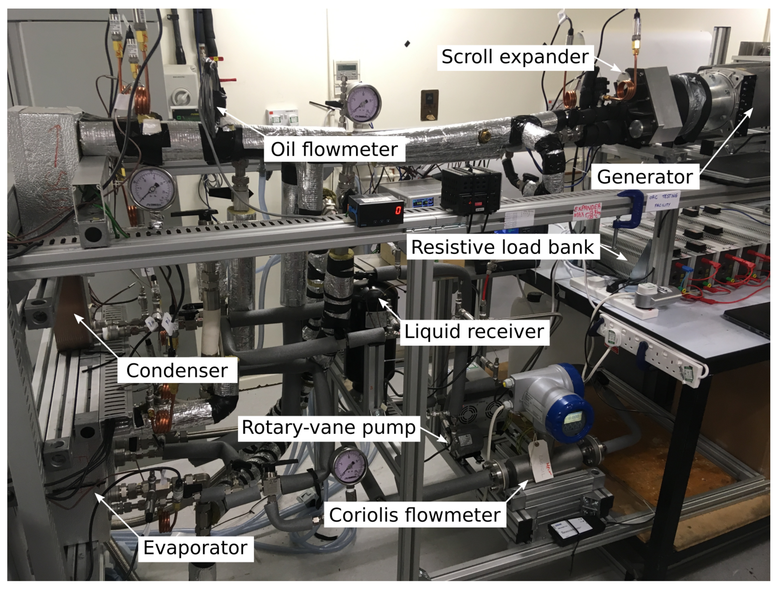
2.1. ORC Testing Facility

The ORC testing facility consists of a rotary-vane pump, brazed-plate evaporator and condenser units and a scroll expander, as described in Figure 1. A liquid receiver is placed in the pump suction line, downstream of the condenser to trap non-condensable gases (such as air) and potentially non-condensed vapour, so that only liquid-phase fluid is sucked into the pump. The expander shaft is connected to a single-phase asynchronous generator with magnetic couplings, so as to avoid leakage from the expander case. The power generated during the expansion of the working-fluid vapour stream is released through a resistive load bank, made of an arrangement of several resistances, providing an equivalent resistance ranging from 10 to 60 Ω and able to dissipate safely up to 2 kW of heat without additional ventilation, as shown in Figure 2. This resistive load is adjusted to determine the optimal expander-shaft rotating speed and investigate the ORC part-load performance. An 18-kWth electric oil heater is used to circulate and heat up a hot Marlotherm SM oil stream, while the supply heat-source temperature to the ORC engine is controlled with a PID controller. Building tap water, supplied at a constant temperature of 18 C, is used to absorb the excess heat rejected in the condenser unit.
Table 1 summarises the basic operating conditions of the apparatus. Various heat-source temperatures, ranging from 100 to 140 C are imposed to assess the ORC system performance under part-load conditions. The engine is operated with R245fa as a working fluid in the current experiments and the mass flow rate is varied by controlling the pump rotational speed. The optimal expander-load resistance and pump rotational speed are determined for each heat-source temperature, maximising either the net power output or the thermal efficiency.

2.2. Time-Resolved Data Acquisition

The ORC test rig is connected to a data acquisition system (namely the DAQ970A model by Keysight Technologies UK Ltd., Wokingham, United Kingdom) and relevant power supplies for data collection. A total of 21 pressure transducers (model PXM309 from Omega Engineering, Manchester, United Kingdom) and 21 thermocouples (T-type) are installed at various positions, mainly at the inlet and outlet of each component in the rig, of which 17 sets of sensors (one pressure transducer and one thermocouple) are used to monitor the state parameters of the working fluid, while the remaining 4 sets are used to record the temperature and pressure of the heat source and the heat sink. Three flow meters—a high-precision Coriolis flowmeter (model Optimass 6000 by Krohne Ltd., Northamptonshire, United Kingdom), a turbine flowmeter and a paddlewheel flowmeter—are used to measure the working-fluid, the heat-source (oil) and the cooling-water mass flowrates, respectively. A power analyser (model HMC 8015 by Rohde & Schwarz UK Ltd., Fleet, United Kingdom) is connected to the generator to measure the voltage, currency, frequency and the consumed electricity by the resistance. The gross power output of the ORC system, that is, the power generated by the scroll expander, is obtained. The power consumed by the pump is measured by a power meter (model PM 231E by Hugo Brennenstuhl Gmbh & Co., Tübingen, Germany), which is subtracted from the gross power output to determine the ORC net power output.
All the aforementioned sensors/measurements are connected to the data acquisition (DAQ) system, which allows quick data acquisition. In addition, the changes of the parameters such as pressure, temperature and other thermodynamic or transport properties can be captured and used for detailed analysis and dynamic investigation of component and system performance, which is of particular importance under transient conditions. The DAQ has a scan speed of 450 channels per second. A steady-state measurement entails data from the 45 channels recorded for 2 min.

2.3. Experimental Procedures

Prior to operating the engine, pressure-leak tests were carried out on the apparatus to ensure its integrity at high pressure during operation. Two safety tests were performed, namely high-pressure test and vacuum test. First, the new rig was subjected to gradually increasing pressure up to 20 bar. Once tests were satisfactory, a vacuum test was carried out to ensure the absence of leak and a value of 2 mbar was reached and maintained. The ORC system was then charged with 10 kg of R245fa using a refrigerant recovery unit. During operation, once all operating parameters are set, the system was allowed to run until a steady-state operation is reached prior to starting data acquisition.
Time-averaging of the data provides both the steady performance and thermodynamic properties of the working fluid throughout the ORC facility and the associated uncertainties obtained from the standard deviation of the time-resolved data around their mean value. The following section details the data processing and system performance analysis from gathered data.

3. Data Analysis

The performance of the ORC system and of its components is assessed through the analysis of the time-resolved data recorded with the DAQ system. This section aims at presenting the numerical methods used to process the raw experimental measurements and derive confidence intervals for the time-mean values. The first- and second-law performance indicators defined in this section are used: (i) to determine the optimal operating parameters (i.e., pump speed and expander load) of the system for given external conditions (i.e., heat-source temperature), (ii) to investigate the part-load and off-design performance of the engine and (iii) to measure and compare the efficiency and exergy destruction rates in the components of the apparatus.

3.1. Time-Averaging and Error Propagation

The uncertainty on the temperature, pressure, volumetric and mass flowrates data acquired during the experimental runs comes from the uncertainty on the sensors readings, u sen (derived from the sensors accuracy as given by the manufacturers) and from the standard deviation, σ , of the time-resolved data around their mean value. The combined uncertainty, u ψ , on a single measurement, ψ ( t ) , is obtained from the summation in quadrature of both contributions to provide a 95% confidence interval on the steady value:
u ψ = u sen 2 + 2 σ ψ N ψ 2 ,
where N ψ is the number of samples over which the mean is determined. The confidence in a processed value, f ( ψ i ) , that depends on a series of raw measurements, ψ i , is later determined using the error propagation theory:
u f = i f ψ i u ψ i 2 .
The steady-state measurements are presented in this paper together with associated uncertainty ranges that represent the standard errors calculated as above.

3.2. Overall ORC Performance

The performance of an ORC engine can be quantified using various indicators. The net power output, W ˙ net , is obtained by subtracting the power consumed by the pump, W ˙ p , from the gross power output, that is, the electrical power generated through vapour expansion, W ˙ exp :
W ˙ net = W ˙ exp W ˙ p .
As a heat engine, the ORC system converts the heat extracted from the heat-source stream, Q ˙ evap , into useful work. The first-law performance indicator used to quantify the effectiveness of this conversion is the thermal efficiency, η th , defined as the ratio of the net power output to the heat input:
η th = W ˙ net Q ˙ evap ,
where Q ˙ evap is calculated from a heat balance across the evaporator on the working-fluid side:
Q ˙ evap = m ˙ wf h evap , out h evap , in .
Finally, the rational performance of the system is reported using the exergy efficiency, η exg , that is the ratio between the actual net useful power output to the ideal reversible power:
η exg = X ˙ out X ˙ in = W ˙ net m ˙ hs x hs , out x hs , in .

3.3. Components Performance

Thermodynamic losses arise from process-scale irreversibilities and component-scale energy losses, both of which can be determined through energy and exergy balances across the various components of the ORC system.

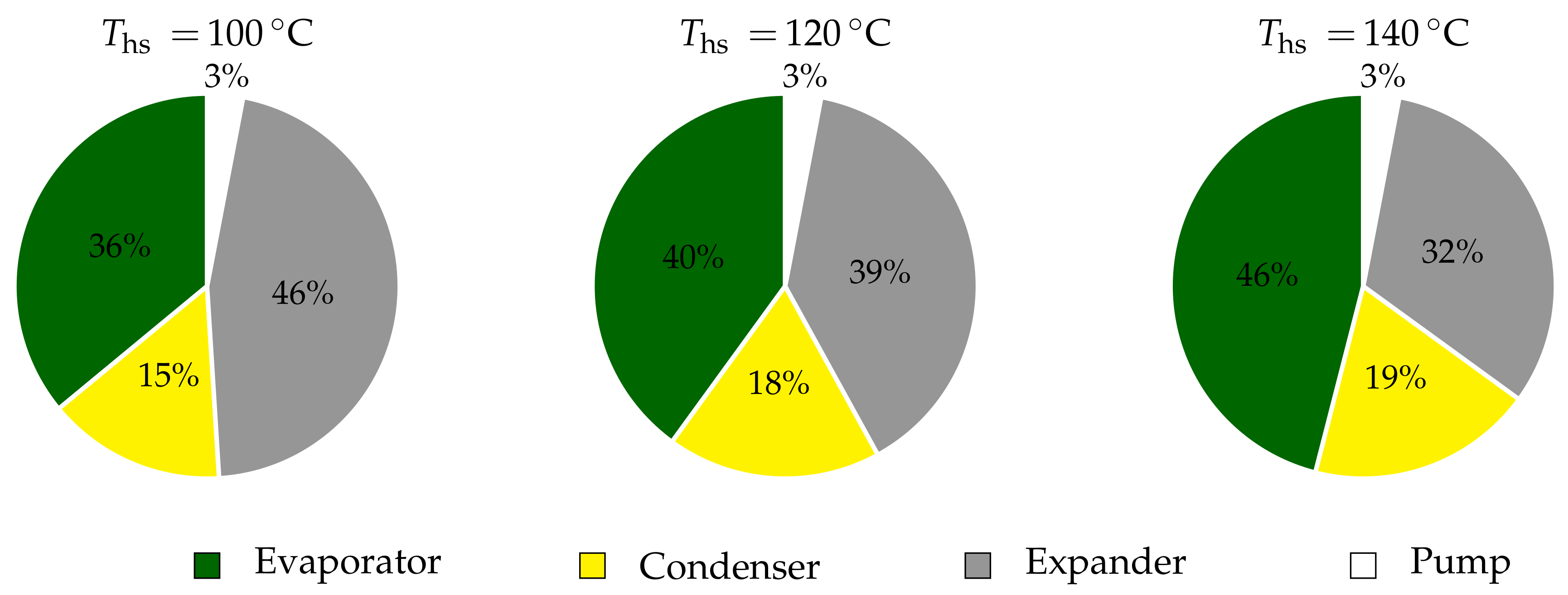
3.3.1. Exergy Destruction Rates

An exergy analysis is conducted to identify and quantify the irreversibility sources and the contribution of all components to the overall performance deterioration. The lost opportunities to produce useful work in the main energy-transfer processes occurring throughout the cycle are obtained from Equations (7) to (10), which define the exergy destruction rates, I ˙ i , in the expander, evaporator, condenser and pump, respectively:
I ˙ exp = m ˙ wf h exp , in h exp , out T 0 s exp , in s exp , out W ˙ exp ,
I ˙ evap = T 0 m ˙ wf s evap , out s evap , in m ˙ hs s hs , out s hs , in ,
I ˙ cond = T 0 m ˙ wf s cond , out s cond , in m ˙ cw s cw , out s cw , in ,
I ˙ p = W ˙ p m ˙ wf h p , out h p , in T 0 s p , out s p , in ,
where the dead-state temperature, T 0 , is set equal to that of the inlet cooling water stream: T 0 = T cw , in .

3.3.2. Expander Performance

The expansion device is a key component of the system, the performance of which strongly influences that of other components and that of the ORC engine. The scroll expander used in the set of experiments presented and analysed in the present study is a positive-displacement expansion machine. Its performance can be further described through components-scale indicators, defined in Equations (11) and (12).
The isentropic effiency, η exp , is , informs about the degradation of the energy quality in this steady-flow device:
η exp , is = W ˙ exp m ˙ wf h exp , in h exp , out is ,
where h exp , out is is a fictive ideal specific enthalpy that would be delivered at the exhaust of an isentropic expander operating between the inlet and outlet pressures: h exp , out is = h P exp , out , S exp , in .
The filling factor, ϕ exp , is the ratio between the actual and theoretical mass flowrate in given operating conditions:
ϕ exp = m ˙ wf ρ exp , in ω exp V exp , disp ,
where ρ exp , in is the expander intake density, V exp , disp the expander built-in displacement and ω exp the scroll spindle speed, to be expressed in Hz when used in the above equation.

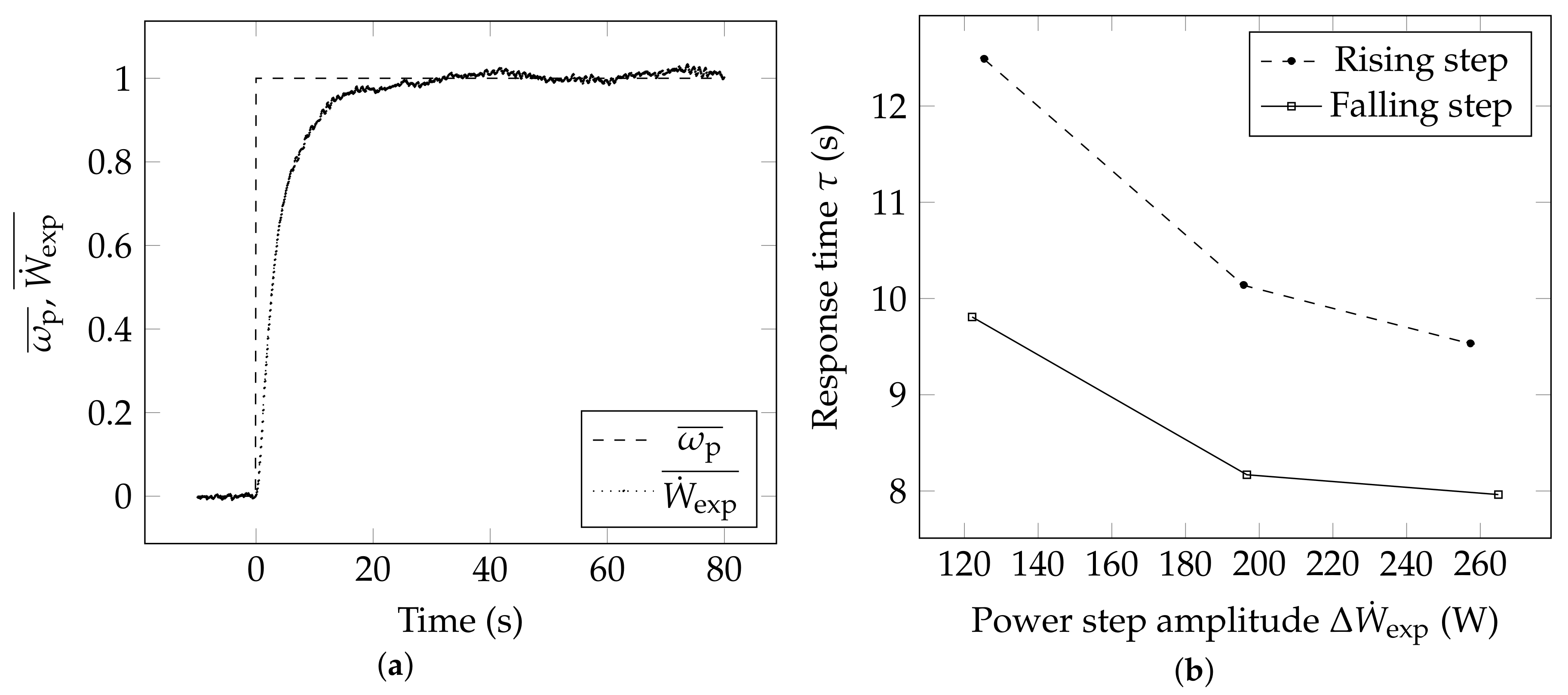
3.4. Transient Data Analysis

The dynamics of the ORC system is investigated by recording the time response of the power generated in the expander to a rising or falling step in pump rotational speed. The time-resolved data, ψ ( t ) , are reported using non-dimensional transient parameters, ψ ¯ ( t ) , defined as:
ψ ¯ ( t ) = ψ ( t ) ψ init ψ fin ψ init .

4. Steady-State ORC Performance

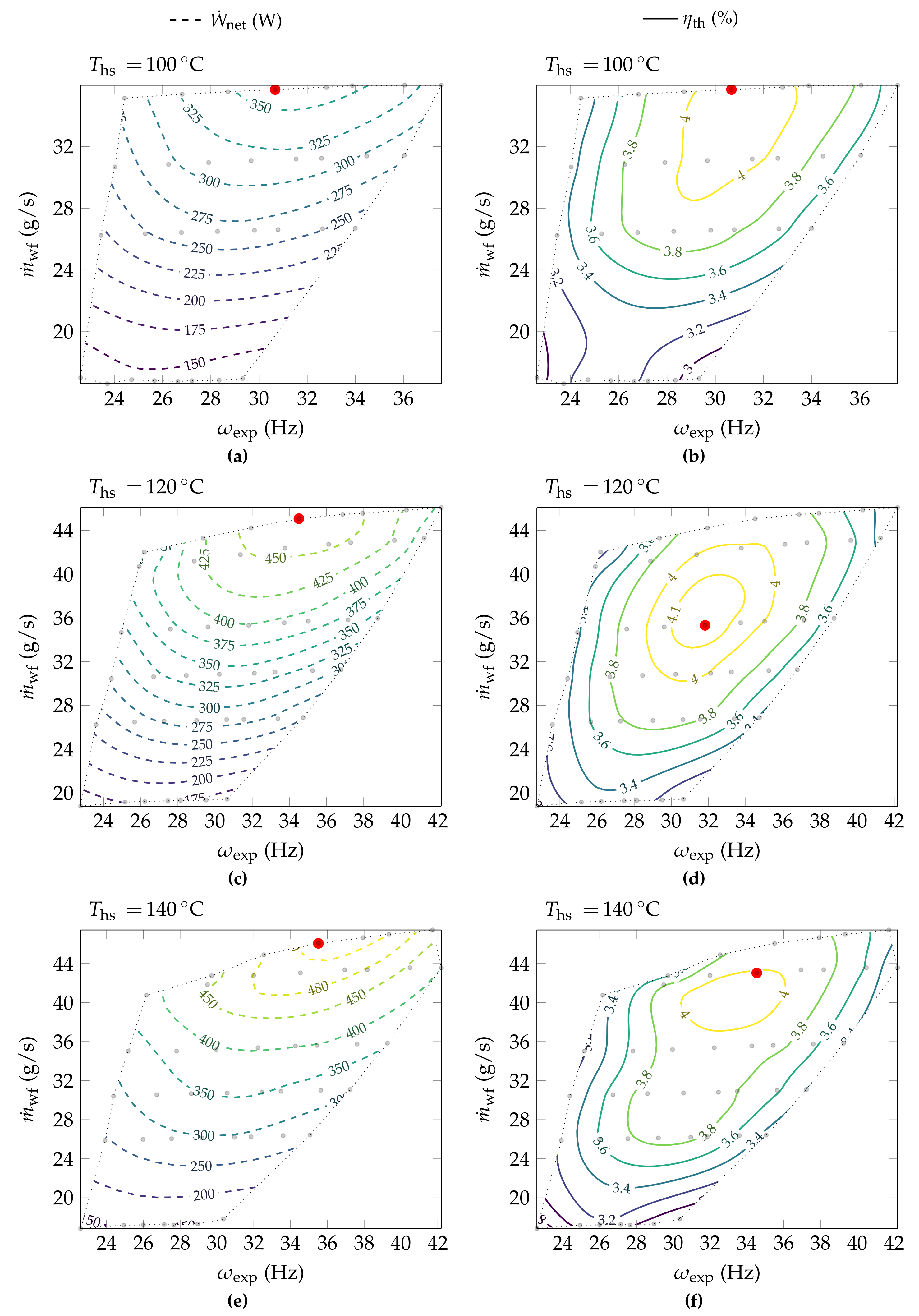
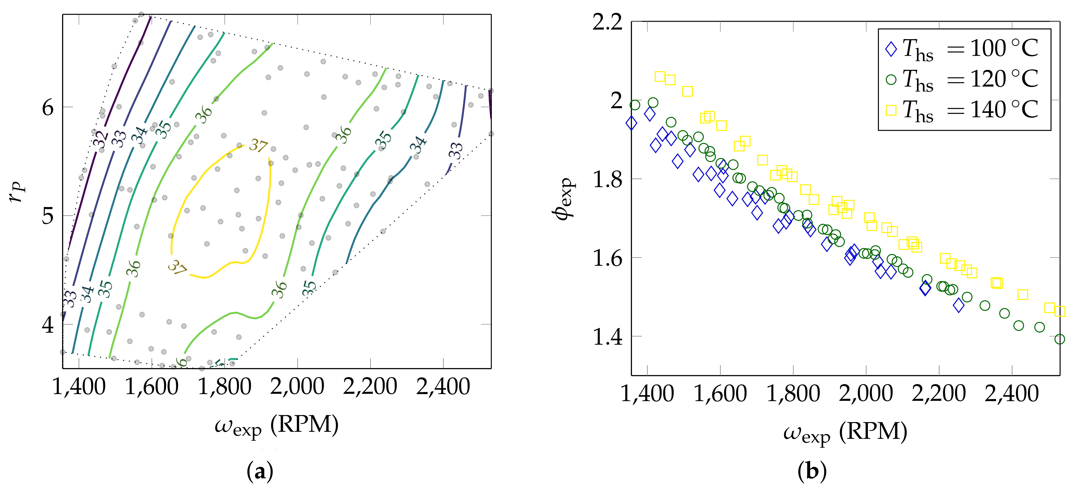
4.1. Operating Parameters Optimisation

The optimal values of the operating– or control–parameters (that are the resistive load, R exp , connected to the expander generator and the pump speed, ω p ) vary with the external conditions, that is, with the cooling-water and heat-source conditions. They are determined for various heat-source temperatures, ranging from 100 to 140 C, through a parametric optimisation that allows to determine the optimum-load and to investigate the part-load performance of the ORC engine, as further explained in Section 4.2.
The pump RPM and expander load are varied through the available ranges and the steady-state ORC performance is recorded systematically. Figure 3 presents an example of a map thus obtained, where the measured gross power output is presented as a function of the decision variables, for a heat-source temperature fixed at 140 C. The value of the optimum expander load does not vary significantly with the imposed pump speed (as it remains around 30 Ω ), while a maximum expander power output of 670 ± 2 W is obtained for a pump rotating velocity of 3000 RPM, as seen clearly from the contours plotted at the base of Figure 3. Although the quantitative description of the optimal performance and associated control parameters is of interest to experimentalists running the testing facility, it does not provide useful data for comparison to model predictions.

4.2. Part-Load Performance Maps

The working fluid mass flowrate m ˙ wf , and the expander spindle speed ω exp , are intelligible variables that can be readily used in comprehensive or heuristic models, together with the system parameters described in Table 1.
Figure 4 presents the part-load performance maps for three investigated temperatures, using both the net power output and the thermal efficiency as performance indicators. The contour plots are made of isometric curves ranging from the lowest to the highest value measured for a set heat-source temperature, which allows to visually ascertain the optimal working conditions. With the heat-source temperature set at 120 C, a maximum thermal efficiency of 4.2 ± 0.1% (that corresponds to a power output of 399 ± 2W and 16.2 ± 0.3% exergy efficiency) is reached for a mass flowrate of 35.3 ± 0.2g/s, according to Figure 4d, while a maximum net power of 470 ± 3W (that corresponds to 3.9 ± 0.1% thermal efficiency) is generated with a working fluid mass flowrate of 45.1 ± 0.3g/s and a resistive load of 36 Ω according to Figure 4c. Unlike the latter, the conditions found to maximise the thermal efficiency constitute a set of global optimum variables, as changing further the pump RPM or expander load would not lead to higher η th values. Higher power production could however be obtained with the current apparatus in similar conditions, if higher working fluid flowrates were investigated—which unfortunately was not possible with the current equipment. Moreoever, the operating conditions corresponding to the maximum net power differ from those that correspond to the maximal thermal efficiency, as a higher mass flowrate also increases the heat input. Table 2 summarises the results obtained for the three heat-source temperatures investigated.
Two objective functions are considered to determine the optimum results listed in Table 2, namely the net power output (max W ˙ net ) and the thermal efficiency (max η th ). Maximising the latter is equivalent to maximising the exergy efficiency, η exg , as the Carnot efficiency is fixed for given heat-source and heat-sink temperatures, which is why only two optimisation scenarios are listed. For a single heat-source temperature, the mass flowrate found to maximise the efficiency is lower than that maximising the power output, as a higher flow leads to a higher heat input. For T hs = 100 C, however, the same operating parameters are found to maximise both the power and efficiency of the system, with a steady cycle that exhibits a relatively low superheat at the exhaust of the evaporator, Δ T sup = 7.2 C. Increasing the working fluid flowrate further actually led to a negative superheat, that is, a two-phase mixture at the expander intake and a drop in thermal efficiency. This limit could however be exceeded with a higher evaporating capacity, either with an increased heat-source mass flowrate or increased evaporator area.
The operating optimum locus, which designates the set of operating parameters that minimise (or maximise) an objective function, is found to vary with the heat-source temperature, as observed in Figure 4. Regardless of the chosen performance indicator, the higher T hs , the higher the working fluid mass flowrate that favours the ORC performance. In other words, the higher the heat-source temperature, the higher the optimum power scale.
It is also worth noting that the maximum thermal efficiency does not vary significantly with the heat-source temperature, as shown in the second part of Table 2, while the exergy efficiency increases with decreasing heat-source temperature. At T hs = 100 C, the thermal efficiency remains low ( η th = 4.1 ± 0.1%) compared either: (i) to the theoretical limit of the Carnot efficiency that is 22% with a heat-sink temperature at 18 C or (ii) to the Chambadal-Novikov efficiency that is a theoretical limit derived from endoreversible thermodynamics, equal to 11.7% in the current conditions. This unexploited potential is accurately measured by the second-law indicator, that is, the exergy efficiency, equal to 18.7 ± 0.3% for the optimal configuration with T hs = 100 C.
The relatively low values of η exg are explained by the large superheat levels at the inlet of the expander unit which denote a lost potential. Indeed, the high superheat at the exhaust of the evaporator reflects that a higher evaporating pressure could have been reached, in turn leading to higher power output for a similar heat input. The limited built-in volume ratio of the scroll expander is the main reason why the overall thermal efficiency stagnates with increasing heat-source temperatures. As further explained in Section 4.2.2, the under-expansion phenomena occurring in the orbiting machine not only decrease the expander isentropic efficiency but also adversely affect the overall ORC efficiency. With increasing the sink-to-source temperature difference, the detrimental effects of the under-expansion losses grow due to an increase of the pressure ratio across the expander.
The thermal efficiency value of 4.2% reported here for a 500-W ORC engine converting heat from a 100-K sink-to-source temperature difference, even though low, is comparable to the most up-to-date experimental data found in the literature, as reported in the review paper by Park et al. [46], which reports thermal efficiency values comprised between 1% and 9% for 0.5- to 1-kW engines. The authors also note that the achieved efficiency increases with the power scale, due to relatively decreasing auxiliary losses. Care must then be taken to compare the efficiency achieved with micro-scale engines to that obtained with large-scale ORCs at a similar sink-to-source temperature difference.

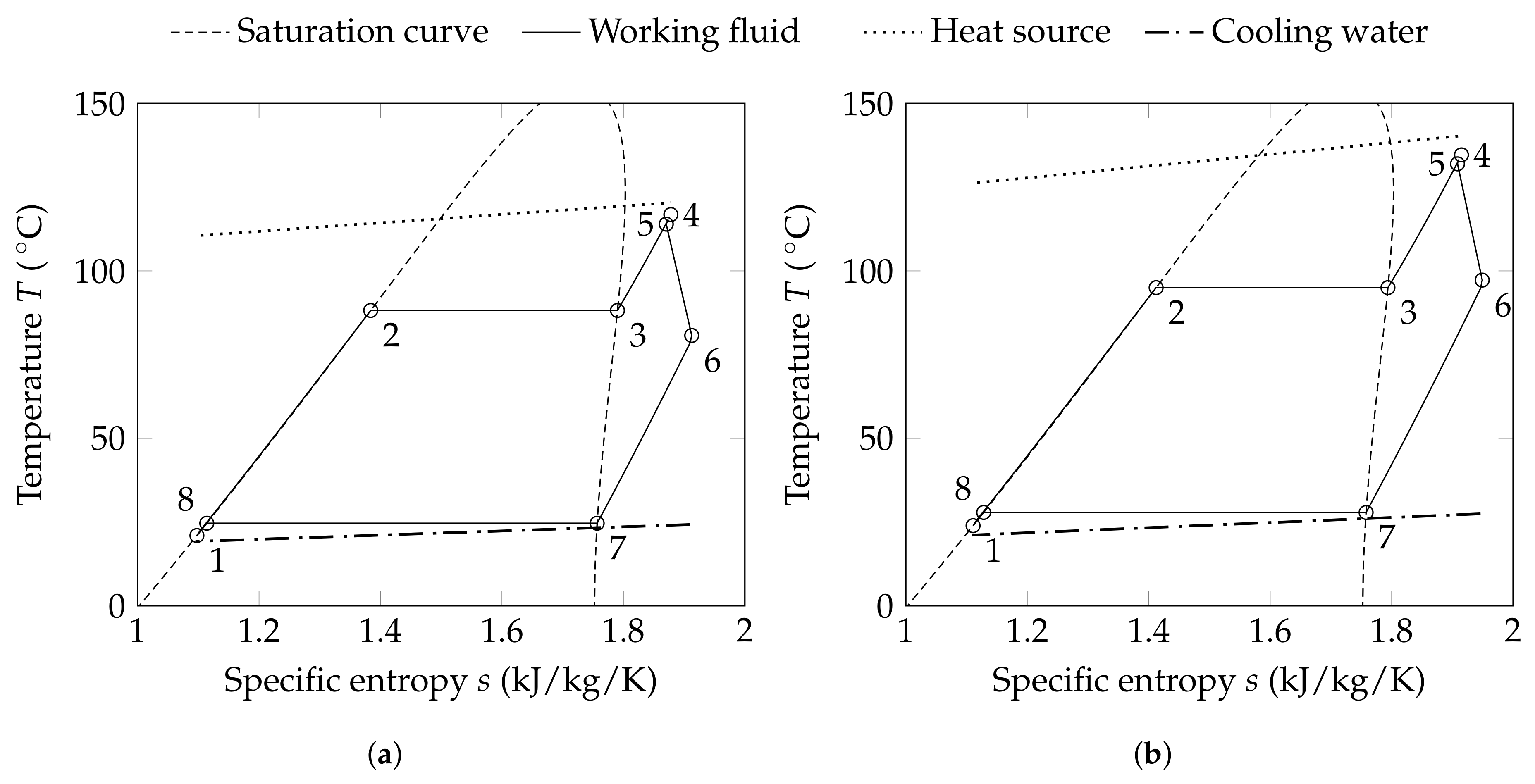
4.2.1. Thermodynamic Analysis of the Optimum Configurations

Control parameters were identified to maximise simultaneously the thermal and exergy efficiencies at various heat-source conditions. This section aims at further analysing the thermodynamic losses in these optimum configurations, both from a first- and second-law point of view.
The steady operation and working-fluid states at key locations of the ORC engine are presented in Figure 5 that shows the temperature-entropy (T-s) diagrams of the optimum (maximising efficiency) configurations, as measured for heat-source temperatures of 120 and 140 C. The working fluid circulated by the pump enters the evaporator in subcooled liquid state (1). The heat transferred from the thermal oil in the evaporator preheats the liquid-phase fluid (1–2), which then undergoes an isothermal evaporation (2–3) and is superheated in the last section of the heat exchanger (3–4). The heat addition (1–4) is a nearly-isobaric process occurring at 9.6 ± 0.06 bar and 11.3 ± 0.06 bar for heat-source temperatures of 120 and 140 C, respectively. Thermal losses in the pipes lower the vapour superheat at the entrance of the expander (5), where the refrigerant expands (5–6), while the work done on the scroll shaft is evacuated in the resistive load bank. The working fluid is finally condensed (6–8) down to a subcooled liquid state before being sucked back into the pump. At the scale of the T-s diagram, the values of the temperature and specific entropy of the fluid at the pump inlet and outlet cannot be distinguished. Point (1) thus refers to both states.
The exergy destroyed in the processes undergone by the working fluid appear graphically in the T-s diagrams. First, the vapour expansion process (5–6) is a non-isentropic process, due both to the thermal losses to the surroundings and to the irreversibility of heat- and mass-transfer occurring within the device. The performance of the scroll expander is further analysed in Section 4.2.2. The mismatch observed between the temperature profiles of the working fluid and heat-source and cooling water streams in the heat exchangers is another source of exergy loss. Indeed, theoretically, the temperature difference between the working fluid and the heating oil could be used to drive a Carnot heat engine. The area contained between the curve (1–4) and the heat-source profile (as well as between (6–8) and the heat-sink profile) is directly proportional to the exergy destruction in the evaporator (or condenser). From Figure 5, it is observed that the exergy destroyed in the evaporator: (i) is larger than that destroyed in the condenser and (ii) increases significantly with the heat-source temperature, while that destroyed in the condenser remains fairly constant between the two diagrams plotted.
The contributions of the different components of the ORC engine to the overall exergy destruction is presented using pie charts in Figure 6. The latter presents the share of the condenser, evaporator, expander and pump in the thermodynamic losses throughout the cycle, for the three heat-source temperatures investigated, as taken from the efficiency-optimum configurations listed in Table 2. It is first observed that the losses incurred in the pump represents a constantly small amount compared to those in other components. The thermal losses and irreversibilities in the evaporator and expander appear to generate the most significant part of the exergy destruction in all cases, while the exergy destruction rate in the condenser remains under 20% of the total, gradually increasing from 15% to 19% for heat-source temperatures ranging from 100 C to 140 C. The lost availability in the evaporator increases significantly with T hs , from 36% to 46% and represents the main source of loss in the configuration selected at 140 C. This confirms the observations made on the T-s diagram. The contribution of the expander, on the other hand, decreases significantly with an increase in heat-source temperature, from 46% down to 32%. The performance of the expansion unit depends on various factors, which are further described in the next section.

4.2.2. Expander Performance

The performance of scroll expanders is adversely affected by four main loss mechanisms that are: (i) radial and flank internal leakage, (ii) heat-transfer losses, (iii) friction losses and (iv) under- or over-expansion losses that occur due to a mismatch between the built-in and actual pressure ratios across the expander [51]. Two performance indicators are presented in Figure 7, using all 124 steady-state measurements gathered through the parametric optimisation study. A part-load performance map of the scroll expander is shown in Figure 7a, where the contours of the (electrical) isentropic efficiency are presented as functions of the pressure ratio imposed across the device, r P and the scroll spindle speed, ω exp . First, it is worth noting that neither the pressure ratio nor the expander rotation speed have independent impact on the efficiency. The overall drop of the expander performance observed when increasing the pressure ratio is due to increased pressure losses and under-expansion phenomena, while the drop of efficiency at high RPMs is mainly due to increased pressure losses through the intake and exhaust ports and increased friction. Under-expansion phenomena are due to a mismatch between: (i) the pressure within the expansion chamber comprised between the involutes of the orbiting machine at the end of the expansion process and (ii) the condensing pressure. In other words, the vapour contained within the crescent-shaped chambers when opening up to the expander exhaust is at a higher pressure than that within the tube leading to the condenser. This mismatch is caused by the limited built-in volume ratio of the expander (equal to 3.5), which does not allow to fully expand the vapour stream. The Joule-Thompson expansion undergone by the under-expanded vapour during the pressure equalisation does not generate any power and thus destroys exergy. This irreversibility adversely affects the expander and overall ORC efficiencies.
At low RPMs, the decrease in efficiency is due to increased thermal and mass-leakage losses. The latter are due to the pressure difference between two adjacent crescent-shaped expansion chambers in the scroll machine, which causes vapour to flow from an upstream high-pressure chamber to a downstream lower-pressure chamber without producing any expansion work. A measure of this mass-leakage phenomenon within the orbiting machine is provided by the filling factor, ϕ exp , plotted in Figure 7b. This indicator can reach values greater than 1 when the mass leakage is important.
As observed in previous studies [52,53], the filling factor is found to decrease monotonically with the expander rotation speed, with values close to those measured in the cited references. The effect of the inlet temperature is also shown, as the filling factors reported for higher temperatures are greater than those at lower temperatures for a fixed RPM. For clarity reasons, errorbars are not shown in Figure 7b; the computed filling factors exhibit relative uncertainties below 2%.

5. Dynamic Characteristics of the ORC Engine

In real-life applications, the working conditions of the ORC engine vary dynamically. The performance variation of the system can be predicted with advanced transient modelling or by integrating time constants in quasi-steady models. Experimental time-resolved data and step-response characteristics are key for developing dynamic system models.
The time response of the expander power output to rising or falling steps in pump rotating velocity is investigated for a heat-source temperature set and held constant at 120 ° C and for an expander resisitve load of 25 Ω . Once a steady operation is attained—with ω p = 1100 RPM—the data collection is initiated before increasing the pump velocity up to 2000 RPM and later decreased back to the initial value. The rising-step response is reported in Figure 8a using non-dimensional parameters, as defined in Equation (13). The rising (or falling) time, τ , that is the time taken for the response to rise (or fall) from 10% to 90% of the steady-state response, is thus determined from the analysis of the transient response. The dynamic test is repeated with various steps, namely between 1100 and 1500, and between 1110 and 2500 RPM. The influence of the step amplitude on the rising and falling times is reported in Figure 8b, using the expander power step amplitude as a reference, Δ W ˙ exp , defined as:
Δ W ˙ exp = W ˙ exp , fin W ˙ exp , init .
All system response time to rising steps in the pump velocity are higher than the corresponding falling steps, by 7% for the largest step tested and by up to 30% for the smallest. In other words, the ORC system reacts more rapidly to a step down in power than to a step up, as long as only the pump speed is varied.
For both rising and falling steps, it is also observed that the response time decreases with increasing step amplitude. This denotes that the ORC-engine inertia has a more significant impact for smaller power steps. Care must then be taken for predicting the dynamic behaviour of ORC engines using quasi-steady models that estimate the time-varying performance based on steady-state results.

6. Conclusions

Driven by the market potential of small- to-medium scale waste-heat recovery (WHR) systems, a significant research effort is being made to develop organic Rankine cycle (ORC) engines in the range 1-kW to 100-kW. The design of technically and, in particular, economically efficient smaller-scale ORC systems is challenging, especially for converting low- to medium-grade thermal energy into useful power. The simultaneous optimisation of the working fluid and of key system components, accounting for part-load and off-design operating conditions, requires accurate physics-based models, able to predict system performance over a wide range of working conditions. High-fidelity experimental measurements are key to inform and validate semi-empirical and comprehensive models.
This paper presents an operational exploration and effort to optimise an experimental non-recuperative 1-kWe ORC engine, comprising a rotary-vane pump, brazed-plate evaporator and condenser units and a scroll expander with an adjustable load. Heat is supplied to the prototype at various temperatures (ranging from 100 C to 140 C in the current experiments) using an 18-kWth heater that circulates thermal oil in the evaporator, while excess heat is rejected to a cooling water stream supplied at 18 C. The optimal operating (or control) parameters, i.e., the pump speed and expander load, are determined for different heat-source temperatures, while the part-load performance of the engine is explored with a total of 124 steady-state data points. The net power output, thermal efficiency and exergy efficiency are reported as functions of the working-fluid mass flow rate and expander-scroll spindle speed, thus providing useful part-load performance maps that can be readily used to inform (develop and/or validate) numerical models. Detailed expander performance maps are also provided—wherein the filling factor and electrical isentropic efficiency of the expansion device are reported as functions of the spindle speed and pressure ratio.
A maximum net power output, that is, the net electrical power generated through the vapour expansion minus the pump consumption, of 508 ± 2 W is reported for a heat-source stream supplied at 140 C, while a maximum 4.2 ± 0.1% thermal efficiency is reached with a heat-source temperature at 120 C. The maximum exergy efficiency, 18.7 ± 0.3%, is reached for the lowest heat-source temperature investigated in this study, 100 C. The contribution of the main components to the exergy destruction in the overall heat-to-power conversion process is determined through a steady-state exergy analysis of the three optimum configurations identified, that is, maximising both the thermal and exergy efficiency. It is found that a negligible amount of the thermodynamic losses occur in the pump, which represents 3% of the overall availability loss, while the two major exergy destruction rates are measured in the expansion and evaporation units, which represent 32% to 46% and 36% to 46%, respectively.
Finally, the dynamic characteristics of the prototype are investigated by measuring the key time constants, as derived from the analysis of the expander power-output time response to a rising or falling step in pump rotating velocity. It is found that the rise time is 7% to 30% higher than the fall time. Both step-response times are also found to decrease with the amplitude of the command step.

Author Contributions

C.K.U., P.S., X.L., J.S. and K.W. designed and constructed the testing facility. C.K.U. conducted the experiments. P.S. performed the data analysis. C.K.U., P.S., X.L., J.S. and K.W. co-authored the paper. P.S., G.S., H.T. and C.N.M. provided advice and support throughout the development of the research and the preparation of the paper.

Funding

This research was funded bythe UK Engineering and Physical Sciences Research Council (EPSRC) [grant number EP/P004709/1]. Data supporting this publication can be obtained on request from [email protected].

Acknowledgments

The authors are very grateful to Dr James Freeman and Dr Steven Lecompte for their continued help with the development of the testing facility.

Conflicts of Interest

The authors declare no conflict of interest.

Nomenclature

I ˙ Exergy destruction rate (W)
m ˙ Mass flowrate (kg/s)
N ψ Number of samples for ψ measurement
Q ˙ Heat flow (W)
r P Pressure ratio (-)
r V Volume ratio (-)
uUncertainty
W ˙ Power (W)
X ˙ Exergy flow (W)
Greek characters
η Efficiency (%)
ϕ Filling factor (-)
ψ Fictive time-resolved measurement
σ Standard deviation
τ Rising or falling time (s)
ω Rotation speed (RPM)
Subscripts and superscripts
cond Condenser
cw Cooling water
disp Displacement
evap Evaporator
exg Exergy
exp Expander
fin Final
hs Heat source
in Inlet/intake/input
init Initial
is Isentropic
out Outlet/exhaust/output
p Pump
sen Sensor
sub Subcooling
sup Superheating
th Thermal
wf Working fluid
Abbreviations
CAMDComputer-aided molecular design
DAQData acquisition system
ICEInternal combustion engine
ORCOrganic Rankine cycle
PIDProportional integral derivative
P&IPiping and instrumentation
RPMRevolutions per minute
WHRWaste-heat recovery

References

  1. Markides, C.N. The role of pumped and waste heat technologies in a high-efficiency sustainable energy future for the UK. Appl. Therm. Eng. 2013, 53, 47. [Google Scholar] [CrossRef]
  2. Markides, C.N. Low-concentration solar-power systems based on organic Rankine cycles for distributed-scale applications: Overview and further developments. Front. Energy Res. 2015, 3, 197–209. [Google Scholar] [CrossRef]
  3. Van Erdeweghe, S.; Van Bael, J.; Laenen, B.; D’haeseleer, W. Optimal combined heat-and-power plant for a low-temperature geothermal source. Energy 2018, 150, 369–409. [Google Scholar] [CrossRef]
  4. Oyewunmi, O.A.; Kirmse, C.J.; Pantaleo, A.M.; Markides, C.N. Performance of working-fluid mixtures in ORC-CHP systems for different heat-demand segments and heat-recovery temperature levels. Energy Convers. Manag. 2017, 148, 1508–1524. [Google Scholar] [CrossRef]
  5. Oyewunmi, O.A.; Markides, C.N. Thermo-economic and heat transfer optimization of working-fluid mixtures in a low-temperature organic Rankine cycle system. Energies 2016, 9, 448. [Google Scholar] [CrossRef]
  6. Pantaleo, A.M.; Camporeale, S.M.; Sorrentino, A.; Miliozzi, A.; Shah, N.; Markides, C.N. Hybrid solar-biomass combined Brayton/organic Rankine-cycle plants integrated with thermal storage: Techno-economic feasibility in selected Mediterranean areas. Renew. Energy 2018. In Press. [Google Scholar] [CrossRef]
  7. Tchanche, B.F.; Papadakis, G.; Lambrinos, G.; Frangoudakis, A. Fluid selection for a low-temperature solar organic Rankine cycle. Appl. Therm. Eng. 2009, 29, 2468–2476. [Google Scholar] [CrossRef] [Green Version]
  8. Kang, S.H. Design and experimental study of ORC (organic Rankine cycle) and radial turbine using R245fa working fluid. Energy 2012, 41, 514–524. [Google Scholar] [CrossRef]
  9. Oyewunmi, O.A.; Taleb, A.I.; Haslam, A.J.; Markides, C.N. An assessment of working-fluid mixtures using SAFT-VR Mie for use in organic Rankine cycle systems for waste-heat recovery. Compt. Therm. Sci. 2014, 6, 301–316. [Google Scholar] [CrossRef]
  10. Freeman, J.; Guarracino, I.; Kalogirou, S.A.; Markides, C.N. A small-scale solar organic Rankine cycle combined heat and power system with integrated thermal energy storage. Appl. Therm. Eng. 2017, 127, 1543–1554. [Google Scholar] [CrossRef]
  11. Tian, H.; Liu, L.; Shu, G.; Wei, H.; Liang, X. Theoretical research on working fluid selection for a high-temperature regenerative transcritical dual-loop engine organic Rankine cycle. Energy Convers. Manag. 2014, 86, 764–773. [Google Scholar] [CrossRef]
  12. Freeman, J.; Hellgardt, K.; Markides, C.N. Working fluid selection and electrical performance optimisation of a domestic solar-ORC combined heat and power system for year-round operation in the UK. Appl. Energy 2017, 186, 291–303. [Google Scholar] [CrossRef] [Green Version]
  13. Oyewunmi, O.A.; Taleb, A.I.; Haslam, A.J.; Markides, C.N. On the use of SAFT-VR Mie for assessing large-glide fluorocarbon working-fluid mixtures in organic Rankine cycles. Appl. Energy 2016, 163, 263–282. [Google Scholar] [CrossRef] [Green Version]
  14. Song, J.; Gu, C.W.; Li, X.S. Performance estimation of Tesla turbine applied in small scale organic Rankine cycle (ORC) system. Appl. Therm. Eng. 2017, 110, 318–326. [Google Scholar] [CrossRef]
  15. Mounier, V.; Olmedo, L.E.; Schiffmann, J. Small scale radial inflow turbine performance and pre-design maps for organic Rankine cycles. Energy 2018, 143, 1072–1084. [Google Scholar] [CrossRef]
  16. Landelle, A.; Tauveron, N.; Revellin, R.; Haberschill, P.; Colasson, S.; Roussel, V. Performance investigation of reciprocating pump running with organic fluid for organic Rankine cycle. Appl. Therm. Eng. 2017, 113, 962–969. [Google Scholar] [CrossRef] [Green Version]
  17. Chatzopoulou, M.A.; Simpson, M.; Sapin, P.; Markides, C.N. Off-design optimisation of organic Rankine cycle (ORC) engines with piston expanders for medium-scale combined heat and power applications. Appl. Energy 2019, 238, 1211–1236. [Google Scholar] [CrossRef]
  18. Shu, G.; Li, X.; Tian, H.; Shi, L.; Wang, X.; Yu, G. Design condition and operating strategy analysis of CO2 transcritical waste heat recovery system for engine with variable operating conditions. Energy Convers. Manag. 2017, 142, 188–199. [Google Scholar] [CrossRef]
  19. Li, X.; Tian, H.; Shu, G.; Zhao, M.; Markides, C.N.; Hu, C. Potential of carbon dioxide transcritical power cycle waste-heat recovery systems for heavy-duty truck engines. Appl. Energy 2019, 250, 1581–1599. [Google Scholar] [CrossRef]
  20. Ramos, A.; Chatzopoulou, M.A.; Freeman, J.; Markides, C.N. Optimisation of a high-efficiency solar-driven organic Rankine cycle for applications in the built environment. Appl. Energy 2018, 228, 755–765. [Google Scholar] [CrossRef]
  21. Ziviani, D.; Gusev, S.; Lecompte, S.; Groll, E.; Braun, J.; Horton, W.; van den Broek, M.; De Paepe, M. Optimizing the performance of small-scale organic Rankine cycle that utilizes a single-screw expander. Appl. Energy 2017, 189, 416–432. [Google Scholar] [CrossRef]
  22. White, M.T.; Oyewunmi, O.A.; Chatzopoulou, M.A.; Pantaleo, A.M.; Haslam, A.J.; Markides, C.N. Computer-aided working-fluid design, thermodynamic optimisation and thermoeconomic assessment of ORC systems for waste-heat recovery. Energy 2018, 161, 1181–1198. [Google Scholar] [CrossRef]
  23. Tocci, L.; Pal, T.; Pesmazoglou, I.; Franchetti, B. Small scale organic Rankine cycle (ORC): A techno-economic review. Energies 2017, 10, 413. [Google Scholar] [CrossRef]
  24. Rahbar, K.; Mahmoud, S.; Al-Dadah, R.K.; Moazami, N.; Mirhadizadeh, S.A. Review of organic Rankine cycle for small-scale applications. Energy Convers. Manag. 2017, 134, 135–155. [Google Scholar] [CrossRef]
  25. Freeman, J.; Hellgardt, K.; Markides, C.N. An assessment of solar-powered organic Rankine cycle systems for combined heating and power in UK domestic applications. Appl. Energy 2015, 138, 605–620. [Google Scholar] [CrossRef] [Green Version]
  26. Boyaghchi, F.A.; Heidarnejad, P. Thermoeconomic assessment and multi objective optimization of a solar micro CCHP based on organic Rankine cycle for domestic application. Energy Convers. Manag. 2015, 97, 224–234. [Google Scholar] [CrossRef]
  27. Garcia-Saez, I.; Méndez, J.; Ortiz, C.; Loncar, D.; Becerra, J.A.; Chacartegui, R. Energy and economic assessment of solar Organic Rankine Cycle for combined heat and power generation in residential applications. Renew. Energy 2019, 140, 461–476. [Google Scholar] [CrossRef]
  28. Tian, H.; Shu, G.; Wei, H.; Liang, X.; Liu, L. Fluids and parameters optimization for the organic Rankine cycles (ORCs) used in exhaust heat recovery of Internal Combustion Engine (ICE). Energy 2012, 47, 125–136. [Google Scholar] [CrossRef]
  29. Shu, G.; Liu, L.; Tian, H.; Wei, H.; Yu, G. Parametric and working fluid analysis of a dual-loop organic Rankine cycle (DORC) used in engine waste heat recovery. Appl. Energy 2014, 113, 1188–1198. [Google Scholar] [CrossRef]
  30. Zhang, H.; Wang, E.; Fan, B. A performance analysis of a novel system of a dual loop bottoming organic Rankine cycle (ORC) with a light-duty diesel engine. Appl. Energy 2013, 102, 1504–1513. [Google Scholar] [CrossRef]
  31. Lecompte, S.; Huisseune, H.; van den Broek, M.; Vanslambrouck, B.; De Paepe, M. Review of organic Rankine cycle (ORC) architectures for waste heat recovery. Renew. Sustain. Energy Rev. 2015, 47, 448–461. [Google Scholar] [CrossRef]
  32. Shi, L.; Shu, G.; Tian, H.; Deng, S. A review of modified organic Rankine cycles (ORCs) for internal combustion engine waste heat recovery (ICE-WHR). Renew. Sustain. Energy Rev. 2018, 92, 95–110. [Google Scholar] [CrossRef]
  33. White, M.T.; Oyewunmi, O.A.; Haslam, A.J.; Markides, C.N. Industrial waste-heat recovery through integrated computer-aided working-fluid and ORC system optimisation using SAFT-γ Mie. Energy Convers. Manag. 2017, 150, 851–869. [Google Scholar] [CrossRef]
  34. Francisco, S.; Delgado, O.; Lutsey, N.; Rotz, D.; Sisken, K.; Kayes, D.; Damon, K.; Salemme, G.; Koeberlein, D.; Mihelic, R.; et al. The U.S. Supertruck Program Expediting the Development of Advanced Heavy-Duty Vehicle Efficiency Technologies; Technical Report; The International Council on Clean Transportation: Washington, DC, USA, 2014. [Google Scholar]
  35. Zhao, R.; Zhang, H.; Song, S.; Tian, Y.; Yang, Y.; Liu, Y. Integrated simulation and control strategy of the diesel engine–organic Rankine cycle (ORC) combined system. Energy Convers. Manag. 2018, 156, 639–654. [Google Scholar] [CrossRef]
  36. Manolakos, D.; Kosmadakis, G.; Kyritsis, S.; Papadakis, G. Identification of behaviour and evaluation of performance of small scale, low-temperature organic Rankine cycle system coupled with a RO desalination unit. Energy 2009, 34, 767–774. [Google Scholar] [CrossRef]
  37. Li, L.; Ge, Y.; Luo, X.; Tassou, S. Experimental investigations into power generation with low grade waste heat and R245fa organic Rankine cycles (ORCs). Appl. Therm. Eng. 2017, 115, 815–824. [Google Scholar] [CrossRef]
  38. Pei, G.; Li, J.; Li, Y.; Wang, D.; Ji, J. Construction and dynamic test of a small-scale organic Rankine cycle. Energy 2011, 36, 3215–3223. [Google Scholar] [CrossRef]
  39. Li, M.; Wang, J.; He, W.; Wang, B.; Ma, S.; Dai, Y. Experimental evaluation of the regenerative and basic organic Rankine cycles for low-grade heat source utilization. J. Energy Eng. 2013, 139, 190–197. [Google Scholar] [CrossRef]
  40. Zheng, N.; Zhao, L.; Wang, X.; Tan, Y. Experimental verification of a rolling-piston expander that applied for low-temperature organic Rankine cycle. Appl. Energy 2013, 112, 1265–1274. [Google Scholar] [CrossRef]
  41. Yu, G.; Shu, G.; Tian, H.; Huo, Y.; Zhu, W. Experimental investigations on a cascaded steam-/organic-Rankine-cycle (RC/ORC) system for waste heat recovery (WHR) from diesel engine. Energy Convers. Manag. 2016, 129, 43–51. [Google Scholar] [CrossRef]
  42. Shu, G.; Zhao, M.; Tian, H.; Huo, Y.; Zhu, W. Experimental comparison of R123 and R245fa as working fluids for waste heat recovery from heavy-duty diesel engine. Energy 2016, 115, 756–769. [Google Scholar] [CrossRef]
  43. Shi, L.; Shu, G.; Tian, H.; Huang, G.; Chen, T.; Li, X.; Li, D. Experimental comparison between four CO2-based transcritical Rankine cycle (CTRC) systems for engine waste heat recovery. Energy Convers. Manag. 2017, 150, 159–171. [Google Scholar] [CrossRef]
  44. Li, X.; Shu, G.; Tian, H.; Huang, G.; Liu, P.; Wang, X.; Shi, L. Experimental comparison of dynamic responses of CO2 transcritical power cycle systems used for engine waste heat recovery. Energy Convers. Manag. 2018, 161, 254–265. [Google Scholar] [CrossRef]
  45. Li, X.; Tian, H.; Shu, G.; Hu, C.; Sun, R.; Li, L. Effects of external perturbations on dynamic performance of carbon dioxide transcritical power cycles for truck engine waste heat recovery. Energy 2018, 163, 920–931. [Google Scholar] [CrossRef]
  46. Park, B.S.; Usman, M.; Imran, M.; Pesyridis, A. Review of organic Rankine cycle experimental data trends. Energy Convers. Manag. 2018, 173, 679–691. [Google Scholar] [CrossRef]
  47. Lemort, V.; Quoilin, S.; Cuevas, C.; Lebrun, J. Testing and modeling a scroll expander integrated into an organic Rankine cycle. Appl. Therm. Eng. 2009, 29, 3094–3102. [Google Scholar] [CrossRef]
  48. Desideri, A.; Hernandez, A.; Gusev, S.; van den Broek, M.; Lemort, V.; Quoilin, S. Steady-state and dynamic validation of a small-scale waste heat recovery system using the ThermoCycle Modelica library. Energy 2016, 115, 684–696. [Google Scholar] [CrossRef]
  49. Hernandez, A.; Desideri, A.; Gusev, S.; Ionescu, C.M.; Den Broek, M.V.; Quoilin, S.; Lemort, V.; De Keyser, R. Design and experimental validation of an adaptive control law to maximize the power generation of a small-scale waste heat recovery system. Appl. Energy 2017, 203, 549–559. [Google Scholar] [CrossRef]
  50. van Kleef, L.M.; Oyewunmi, O.A.; Markides, C.N. Multi-objective thermo-economic optimization of organic Rankine cycle (ORC) power systems in waste-heat recovery applications using computer-aided molecular design techniques. Appl. Energy 2019, 251, 112513. [Google Scholar] [CrossRef]
  51. Lemort, V.; Legros, A. Positive displacement expanders for organic Rankine cycle systems. In Organic Rankine cycle (ORC) power systems: Technologies and applications; Series in Energy: Number 107; Woodhead Publishing: Amsterdam, The Netherlands, 2016; pp. 361–396. [Google Scholar]
  52. Woodland, B.J.; Braun, J.E.; Groll, E.A.; Horton, W.T. Experimental testing of an organic Rankine cycle with scroll-type expander. In Proceedings of the International Refrigeration and Air Conditioning Conference, West Lafayette, IN, USA, 16–19 July 2012. Paper 1324. [Google Scholar]
  53. Dumont, O.; Parthoens, A.; Dickes, R.; Lemort, V. Experimental investigation and optimal performance assessment of four volumetric expanders (scroll, screw, piston and roots) tested in a small-scale organic Rankine cycle system. Energy 2018, 165, 1119–1127. [Google Scholar] [CrossRef] [Green Version]
Figure 1. Piping and instrumentation (P&I) diagram of the organic Rankine cycle (ORC) apparatus.
Applsci 09 03024 g001
Figure 2. Picture of the experimental testing facility.
Applsci 09 03024 g002
Figure 3. ORC gross power output part-load performance map as function of the pump speed, ω p and the expander load, R exp for a heat-source temperature set at 140 C.
Applsci 09 03024 g003
Figure 4. ORC part-load performance maps: contour plots of the net power output, W ˙ net (a,c,e) and of the thermal efficiency, η th (b,d,f), as functions of the expander spindle speed, ω exp and of the working fluid mass flowrate, m ˙ wf , for heat-source temperatures of 100 (a,b), 120 (c,d) and 140 C (e,f). Performance map obtained from cubic-spline interpolation of experimental data (indicated as grey dots). The optimum values highlighted in red are further described in Table 2.
Applsci 09 03024 g004
Figure 5. Temperature-entropy diagrams presenting the steady operation of the ORC engine with efficiency-optimum operating conditions for heat-source temperatures of: (a) 120 and (b) 140 C. Working-fluid state reported at key locations of the facility: (1) pump inlet or condenser outlet, (2) evaporator saturated liquid, (3) evaporator saturated vapour, (4) evaporator exhaust, (5) expander inlet, (6) expander outlet, (7) condenser saturated vapour, (8) condenser saturated liquid.
Applsci 09 03024 g005
Figure 6. Exergy destruction contributions of the various components of the ORC engine.
Applsci 09 03024 g006
Figure 7. (a) Expander isentropic efficiency, η exp , is expressed in %, mapped against the scroll spindle speed, ω exp and the pressure ratio, r P . Performance map obtained from cubic-spline interpolation of experimental data, indicated as grey dots on the map, obtained for heat-source temperatures ranging from 100 to 140 C. (b) Expander filling factor as a function of the expander spindle speed.
Applsci 09 03024 g007
Figure 8. (a) Dynamic response of the ORC system to a step in pump veloctiy from 1100 to 2000 RPM at fixed heat-source temperature ( T hs = 120 C) and expander load ( R exp = 25 Ω ). (b) Rising and falling step-response times as functions of the step amplitude in expander power.
Applsci 09 03024 g008
Table 1. ORC testing facility characteristics.
Working fluid
Refrigerant-R245fa
Mass flowrate m ˙ wf [20–60] g/s
Heat source
Thermal fluid-Marlotherm oil
Mass flowrate m ˙ hs 1.4 kg/s
Available supply temperature T hs = T hs , in [80–150]  C
Heat sink
Cooling fluid-Water
Mass flowrate m ˙ cw 0.4 kg/s
Supply temperature T cw 18 C
Pump
Model-TMFR2 (Fluid-o-Tech S.R.L., Milano, Italy)
Type-Magnet-driven rotary vane pump
Pump rotating speed ω p [1100–3000] RPM
Heat exchangers
Condenser model-CB60-30H-F (Alfa Laval Lund AB, Lund, Sweden)
Condenser type-Brazed-plate
Condenser area-1.62 m 2
Evaporator model-B12Lx18 (SWEP, Didcot, United Kingdom)
Evaporator type-Brazed-plate
Evaporator area-0.45 m 2
Expansion machine
Model-E15H22N4.25 (Air Squared Inc., Broomfield, USA)
Type-Scroll expander
Displacement V exp , disp 14.5cm 3 /rev
Nominal power-1kWe
Built-in volume ratio r v 3.5
Table 2. Optimum operating conditions for various heat-source temperatures, which maximise either the net power output or thermal (and exergy) efficiency. The points described in this table are highlighted in red in Figure 4.
T hs W ˙ net η th η exg η exp , is m ˙ wf ω exp P evap P cond Δ T sup Δ T sub
( C)(W)(%)(%)(%)(g/s)(Hz)(bar)(bar)( C)( C)
max W ˙ net
100359 ± 44.1 ± 0.118.7 ± 0.337 ± 0.435.7 ± 0.230.1 ± 0.39.0 ± 0.061.5 ± 0.067 ± 2.13.4 ± 2.1
120470 ± 33.9 ± 0.115.4 ± 0.236.4 ± 0.345.1 ± 0.334.5 ± 0.111.2 ± 0.061.6 ± 0.0618 ± 2.13.7 ± 2.1
140508 ± 23.9 ± 0.113.5 ± 0.236.6 ± 0.346.1 ± 0.335.5 ± 0.111.8 ± 0.061.75 ± 0.0635 ± 2.14.4 ± 2.1
max η th (= max η exg )
100359 ± 44.1 ± 0.118.7 ± 0.337 ± 0.535.7 ± 0.230.1 ± 0.39.0 ± 0.061.5 ± 0.067.2 ± 2.13.4 ± 2.1
120399 ± 24.2 ± 0.116.2 ± 0.337.3 ± 0.435.3 ± 0.231.8 ± 0.19.6 ± 0.061.5 ± 0.0626 ± 2.14.2 ± 2.1
140493 ± 24.1 ± 0.113.9 ± 0.336.8 ± 0.443 ± 0.334.5 ± 0.211.3 ± 0.061.73 ± 0.0637.5 ± 2.14.3 ± 2.1

