Article

Effect of Steel Casing on Vertical Bearing Characteristics of Steel Tube-Reinforced Concrete Piles in Loess Area

School of Highway, Chang’an University, Xi’an 710064, China
*
Author to whom correspondence should be addressed.
Appl. Sci. 2019, 9(14), 2874; https://doi.org/10.3390/app9142874
Submission received: 28 May 2019 / Revised: 15 July 2019 / Accepted: 16 July 2019 / Published: 18 July 2019
(This article belongs to the Section Civil Engineering)

Abstract

:
This study aims at investigating the effect of steel casing on vertical bearing characteristics of steel tube-reinforced concrete piles in loess area by centrifugal model test. Five piles were selected, one of them was a conventional reinforced concrete pile which was 35 cm in length and 2.5 cm in diameter as a contrast pile, and the length of steel casing for the remaining four steel tube-reinforced concrete piles was 8 cm, 12 cm, 16 cm, and 20 cm respectively. The results show that the axial force, unit skin friction, tip resistance, and shaft resistance of steel tube-reinforced concrete piles with different steel casing lengths were different from conventional reinforced concrete pile. Additionally, the ultimate bearing capacity of steel tube-reinforced concrete piles was compared with a conventional reinforced concrete pile. Moreover, advantages of steel casing in pile foundation engineering were summarized. The results of this study can provide reference for vertical bearing characteristics of steel tube-reinforced concrete piles in loess area.

1. Introduction

In recent years, with the rapid development of bridge engineering, pile foundation has attracted the attention of designers as an important part of highway bridge construction [1,2,3,4]. On the one hand, some researchers established theoretical models to analyze the bearing characteristics of piles [5,6,7,8]. On the other hand, some researchers studied the bearing characteristics of piles through field or indoor experiments [9,10,11,12]. Moreover, some researchers studied the bearing characteristics of piles through simulation experiments [13,14,15]. In the process of pile foundation construction, various types of soil will be encountered. Loess is the dominant soil in Northwest China, accounting for 72.4% of the total loess area in China. In addition, China introduced the conception of the “New Silk Road Economic Belt” in 2013, and most of the soil in this area is loess, which brings great opportunity and challenge to the construction of pile foundation in loess area [16,17,18,19,20,21]. When cast-in-place bored piles are used in loess area, the steel casing is usually used to stabilize the borehole wall or solve the slurry leakage problem of huge caves. Because of the difficulty in recycling, the steel casing is sometimes no longer recycled after pile forming, so as to form a concrete-filled steel tube composite structure with reinforced concrete materials, which is called steel tube-reinforced concrete piles in this study. When steel casings are recycled, they are called conventional reinforced concrete piles.
There are some researches on pile foundation in loess area. Gao et al. [22] tested three squeezed branch and plate piles in loess area and proposed the safety factor for the three piles. Wang et al. [23] investigated the negative skin friction along piles caused by earthquake in loess area and developed a method to estimate the negative skin friction. Zhang et al. [24] found that down-hole dynamic compaction pile could improve 50 m collapsible loess when the pile spacing is reasonable by field tests. Xing and Liu [25] carried out water immersion tests to study the different pile types on negative skin friction of pile foundations in loess regions and found NSF of the bored concrete pile was smallest. Zhou et al. [26] used static load test and post-grouting technology; the settlement parameters of post-grouting piles in loess area were analyzed and optimized. However, the above research is on the bearing characteristics of concrete piles in loess area; there is little research on the effect of steel casing length on vertical bearing characteristics of steel tube-reinforced concrete piles in loess area. Compared with field tests, more and more centrifugal model tests have been applied recently in various engineering due to its virtue of quick construction and low engineering cost. Simultaneously, the results of centrifugal model tests are consistent with those of field tests, which had been confirmed by a large number of studies, suggesting that centrifugal model tests have a certain accuracy and reliability [27,28,29,30,31,32].
Based on this, the effect of steel casing on vertical bearing characteristics of steel tube-reinforced concrete piles in loess area was investigated by centrifugal model test, which includes the axial force, unit skin friction, tip resistance, shaft resistance, and ultimate bearing capacity. In addition, advantages of steel casing in pile foundation engineering were summarized.

2. Methodology

2.1. Purpose of the Test

Field tests always have slow construction and high engineering cost. In order to quickly study the bearing characteristics of the pile (with dimensions of 35 m in length and 2.5 m in diameter) in the loess area and analyze the effect of steel casing on its bearing characteristics, a series of centrifugal model tests were conducted. In addition, the results of centrifugal model test can be converted to actual results in the field through similar relationships [33].

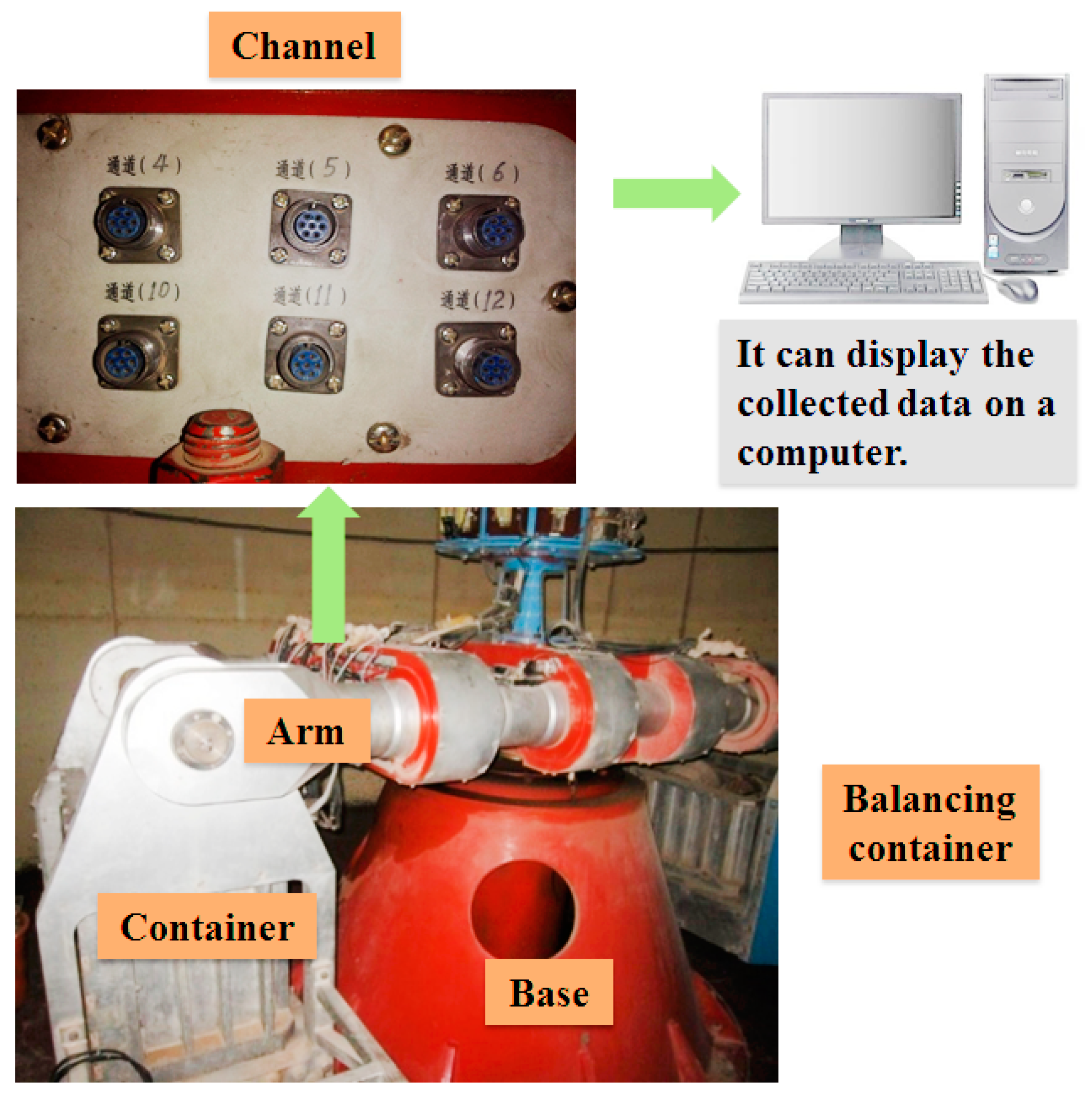
2.2. Centrifuge Equipment
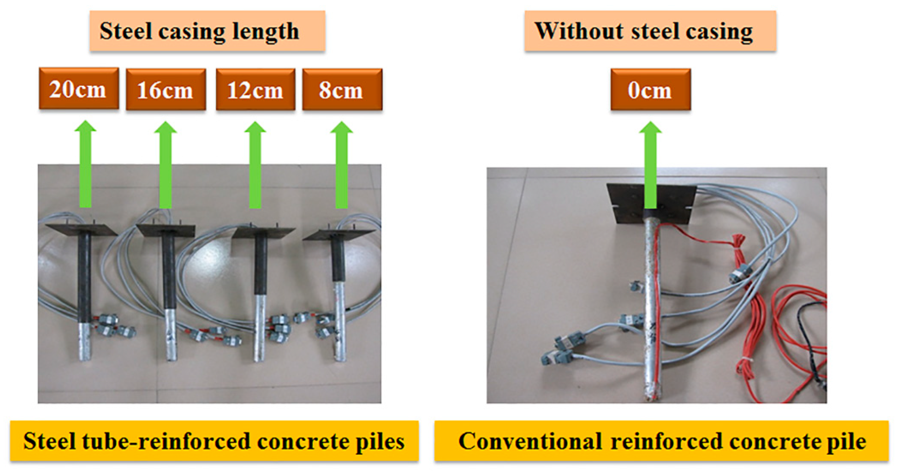
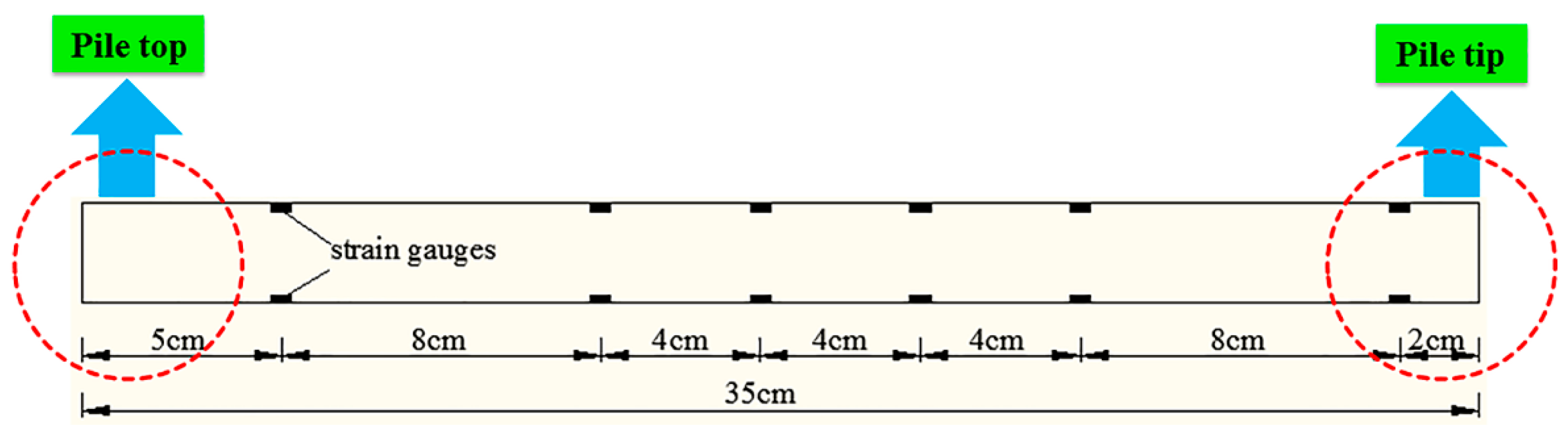
In this study, TLJ-3 type geotechnical centrifuge was produced by china academy of engineering physics, which is located in Mianyang City, Sichuan Province, China, as shown in Figure 1; the maximum centrifugal acceleration of TLJ-3 type geotechnical centrifuge is 200 g; it can accommodate up to 1000 kg (including container quality and material quality) at the 60 g level, which means 300 kg at the 200 g level, so it can accommodate up to 600 kg (including container quality and material quality) at the 100 g level. As a beam type of centrifuge, it has a container at the end of the arm and a balancing container at the opposite side to balance the weight. The container used in this study is made of steel, with dimensions of 70 cm in length, 50 cm in height and 36 cm in width. There are 40 channels on the centrifuge to collect data, which can display the collected date on a computer. The designed centrifugal model tests satisfied the similitude laws [33]. Detailed similitude ratios (i.e., parameter ratios between the model and the prototype) are provided in Table 1.

2.3. Model Pile

In this study, five model piles were prepared for the centrifugal model tests. Four model piles with steel casing were called steel tube-reinforced concrete piles; the model pile without steel casing was called conventional reinforced concrete pile. The steel casing length of four steel tube-reinforced concrete piles was 20 cm, 16 cm, 12 cm, and 8 cm, as shown in Figure 2.
Because cast in-situ piles are made up of reinforced concrete, it is difficult to form and take a long time to make a model pile with the same concrete as the prototype strength. Therefore, according to the similarity principle, the model material similar to the mechanical properties of the prototype pile is selected as far as possible, and under axial load, the model material is controlled by the axial stiffness EA (elastic modulus and cross-sectional area) of its prototype, as shown in Equation (1). At present, the commonly used model pile materials are steel pipe, aluminum pipe, plastic, gypsum and so on [34]. In this study, the conventional reinforced concrete pile was simulated by aluminum pipe. Table 1 shows the specifications of the conventional reinforced concrete pile. Because the Young′s modulus of the prototype reinforced concrete pile is 18.7 GPa, a similarity rate of 100 is available according to Equation (1) and Table 2. This is the reason why centrifugal acceleration was carried out at the 100 g level.
n 2 E m A m = E p A p = n 2 E m π ( R m 2 r m 2 ) = E p π R p 2
where E m is Young′s modulus of model; E p is Young′s modulus of the proto-type; A m is the cross-sectional area of the model; A p is the cross-sectional area of the proto-type; n is the similarity rate; R m is the outer radius of model; r m is the inner radius of model; and R p is the radius of the proto-type.
Four model piles of steel tube-reinforced concrete piles have the same materials as the conventional reinforced concrete pile. The steel casing was simulated by steel pipe; Table 3 shows the specifications of the steel tube-reinforced concrete piles.
In order to ensure the integrity of the strain gauge during the testing process, the model piles were cut vertically; strain gauges were laid out in the model pile. After the strain gauges were affixed, the model piles were pasted and restored by epoxy resin, and the position of the pile shaft strain gauges were laid out as shown in Figure 3. Because the pile that enters the soil layer is 30 cm deep, the pile length is 35 cm, so the position of the first group of strain gauges is 5 cm from the top of the pile. The second to the fifth group of strain gauges are positioned according to the length of the steel casing. In order to save the number of strain gauges and reflect the strain near the bottom of the pile, the sixth group of strain gauges is arranged at 2 cm from the bottom of the pile.
The aluminum pipe and steel pipe are bonded by epoxy resin, regardless of the friction between them. Finally, sandpaper will be used to polish the outer surface of the model pile, so that their bearing characteristics are closer to the actual pile [33]. Tip resistance of the pile can be obtained by earth pressure cell, which is installed at the bottom of the pile (see Figure 4).

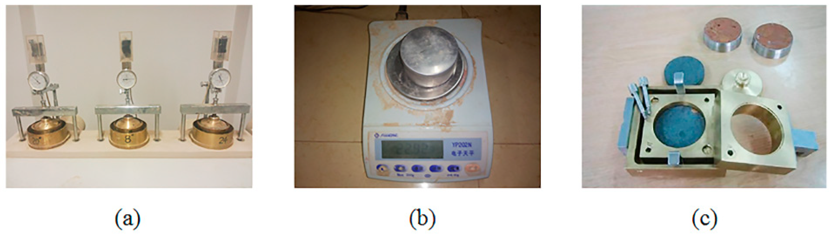
2.4. Physical Properties of Loess

The soil samples were loess; the main physical properties of loess were tested by an oedometer test (Figure 5a), a moisture content test (Figure 5b), and a direct shear test (Figure 5c). Density is calculated according to the mass and volume of the soil. Compression modulus was obtained by the oedometer test. The moisture content was determined from the moisture content test. The cohesion and internal friction angle were obtained by the direct shear test. The test results are shown in Table 4.

2.5. Test Procedure

The main test procedures are shown in Figure 6, and the specific steps are set out below:
  • In order to ensure that the density of soil in the container is consistent, a certain mass of soil is compressed into a certain volume. In this study, the soil density is 1.7 g/cm3; each layer of the soil is compressed to 2 cm, because the container length is 70 cm; width is 36 cm; and each layer of the soil is compressed to 5040 cm3, so it can be calculated that each layer requires a soil mass of 8568 g. First, 8568 g of soil was weighed and placed in plastic bags, then a shovel was used to spread the soil evenly into the container, and finally a vibrator was used to compress the soil to 2 cm; the operation was repeated 20 times and the soil was filled to 40 cm high. Then the hole was drilled according to the pile position; the position of the model piles are shown in Figure 7. The depth of the hole was 30 cm; the aperture was slightly smaller than the pile diameter, so that the shaft resistance between the pile and soil was closer to the actual value. Finally, the pile was pressed into the hole.
  • The container was put into the centrifuge by hoisting machine.
  • First, the displacement meter was mounted on the inverse force frame to measure top displacement. Then the reverse force frame was fastened to the container by bolts. Finally, strain gauges, earth pressure cells and the displacement meter were connected with the centrifuge channel, which can obtain the data from the computer.
  • Five minutes preliminary operation at the 100 g level was conducted.
  • The test data was transferred to the computer.
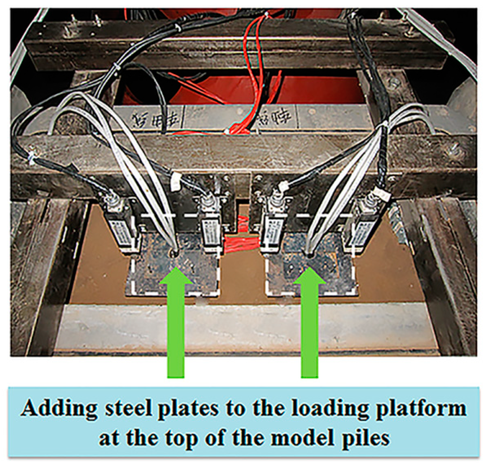
  • Load was increased after one load ended, and then the steps above were repeated. Vertical loading was achieved by adding steel plates to the loading platform at the top of the model pile, and the vertical loading was divided into eight levels; the weight of the loading platform itself can be considered as the first stage load, the loading size is 225 N, 450 N, 675 N, 900 N, 1125 N, 1350 N, 1575 N, and 1800 N. The loading device is shown in Figure 8.

3. Results and Discussion

The results of centrifugal model test and the actual results show only proportional transformation; the law is consistent, and so the following analysis of the bearing characteristics will be directly using the results of centrifugal model test. Because the ultimate bearing capacity is the most important parameter in the practical application of pile foundation, it is converted to the ultimate bearing capacity of the prototype pile, and the lifting value of the steel casing to the ultimate bearing capacity is reflected by the truck whose quality is 5000 kg.

3.1. Effect of Steel Casing on Bearing Capacity

The load–settlement curve of steel tube-reinforced concrete piles is shown in Figure 9.
As shown in Figure 9, under the same settlement, the longer the length of the steel casing, the greater the load the pile can bear. The load–settlement curve is always used to judge the ultimate bearing capacity of piles. There are two different criteria. In the first, the ultimate bearing capacity is the load when the settlement mutates. In the second, the ultimate bearing capacity refers to the load corresponding to the settlement of 5% of the pile diameter [35]. Since the settlement in Figure 9 does not mutate, the second method is used to determine the ultimate bearing capacity of piles.
The ultimate bearing capacity of steel tube-reinforced concrete piles is shown in Figure 10.
As shown in Figure 10, when the steel casing length is 0 cm, 8 cm, 12 cm, 16 cm, and 20 cm respectively, the vertical ultimate bearing capacity is 892.6 N, 937.8 N, 957.5 N, 964.6 N, and 968.2 N. With the increase of the steel casing length, the vertical ultimate bearing capacity of steel tube-reinforced concrete piles shows a gradual increasing trend. The main reason is that the diameter of the steel casing is slightly larger than the borehole size, which has an extrusion effect on the soil, and with the increase of the length of the steel casing, the extrusion area of the steel casing and the soil increases, and the larger the shaft resistance that can be obtained. When the steel casing length is less than 12 cm, the vertical ultimate bearing capacity of steel tube-reinforced concrete piles increases rapidly, and when the steel casing length is greater than 12 cm, the vertical ultimate bearing capacity of steel tube-reinforced concrete piles increase slowly. Additionally, when the steel casing length of steel tube-reinforced concrete piles is 8 cm, the lifting rate of ultimate bearing capacity is 5.1%, see Figure 10 and Equation (2), and it can be seen that the existence of the steel casing can improve the ultimate bearing capacity. When the steel casing length of steel tube-reinforced concrete piles is 16 cm, the lifting rate of ultimate bearing capacity is 8.1%; it is only 0.8% more than steel tube-reinforced concrete piles whose steel casing length is 12 cm. The main reason is that when the length of the steel casing exceeds a certain value, this means that the growth of length has not had much effect on the bearing capacity.
α v = F i F 0 F 0
where α v is the lifting rate of the ultimate bearing capacity; F 0 is the ultimate bearing capacity of the conventional reinforced concrete pile; and F i is the ultimate bearing capacity of the steel tube-reinforced concrete piles with steel casing of 8 cm, 12 cm, 16 cm, and 20 cm.
According to Table 1, a similitude ratio of force is 1: n2 and n is 100 in this study, so the prototype force is 10,000 times the model force. When the steel casing length of model piles is 0 cm, 8 cm, 12 cm, 16 cm, and 20 cm respectively, the vertical ultimate bearing capacity of model piles is 892.6 N, 937.8 N, 957.5 N, 964.6 N, and 968.2 N. So when the steel casing length of prototype piles is 0 m, 8 m, 12 m, 16 m, and 20 m, respectively, the vertical ultimate bearing capacity of prototype piles is 8926 kN, 9378 kN, 9575 kN, 9646 kN, and 9682 kN. The lifting value of ultimate bearing capacity is 452 kN, 649 kN, 720 kN, and 756 kN, see Equation (3). If there is a truck whose quality is 5000 kg, the lifting value of the ultimate bearing capacity can be converted into gravity for 9.2 trucks, 13.2 trucks, 14.7 trucks, and 15.4 trucks respectively, as shown in Figure 11.
P L = P i P 0
where P L is the lifting value of the ultimate bearing capacity; P 0 is the ultimate bearing capacity of the conventional reinforced concrete pile (proto-type); and P i is the ultimate bearing capacity of the steel tube-reinforced concrete piles with steel casing of 8 m, 12 m, 16 m, and 20 m (proto-type).

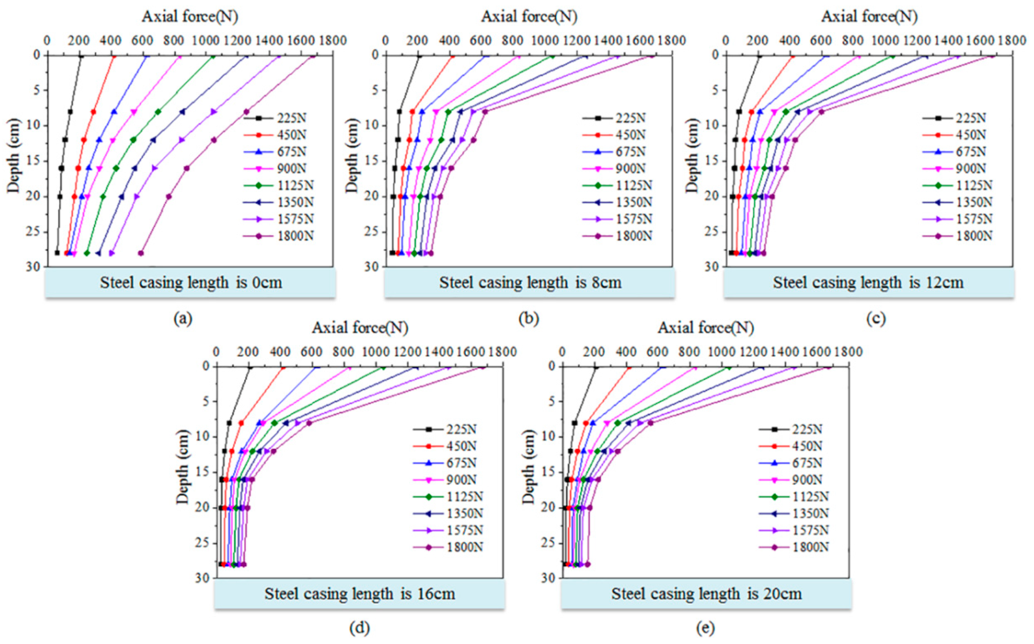
3.2. Effect of Steel Casing on Axial Force

Pile shaft strain data can be obtained by computer. Axial force of the pile shaft can be obtained by Equation (4).
P = E ε A
where P is the axial force of the pile; E is Young′s modulus of the pile; ε is strain of the pile; and A is the cross-sectional area of the pile.
The effect of steel casing on the axial force of steel tube-reinforced concrete piles is shown in Figure 12.
As shown in Figure 12, whether there is steel casing or no steel casing, at the same depth, when the pile top load gradually increases, the axial force of the pile shaft shows a gradual increasing trend. Under the same level load, when there is no steel casing, the axial force of the pile shaft changes slowly along the direction of pile, and the axial force curve of the pile shaft is relatively flat; when there is steel casing, the axial force of the pile shaft decreases rapidly along the direction of the pile, and the curve becomes steeper. For example, when the load is 1800 N, the depth is from 0–8 cm, and when the steel casing length is 0 cm, 8 cm, 12 cm, 16 cm, and 20 cm, the slope is approximately 55, 139, 142, 144, and 148, respectively, see Equation (5). The main reason is that as the length of the steel casing increases, more axial forces are transmitted to the soil through the form of shaft resistance.
S = P i P i + 1 Δ Z
where S is the slope of two axial forces; P i is the axial force of the pile, i is the number of strain gauges, 1~6 from top to bottom; and Δ Z is depth difference of two strain gauges.

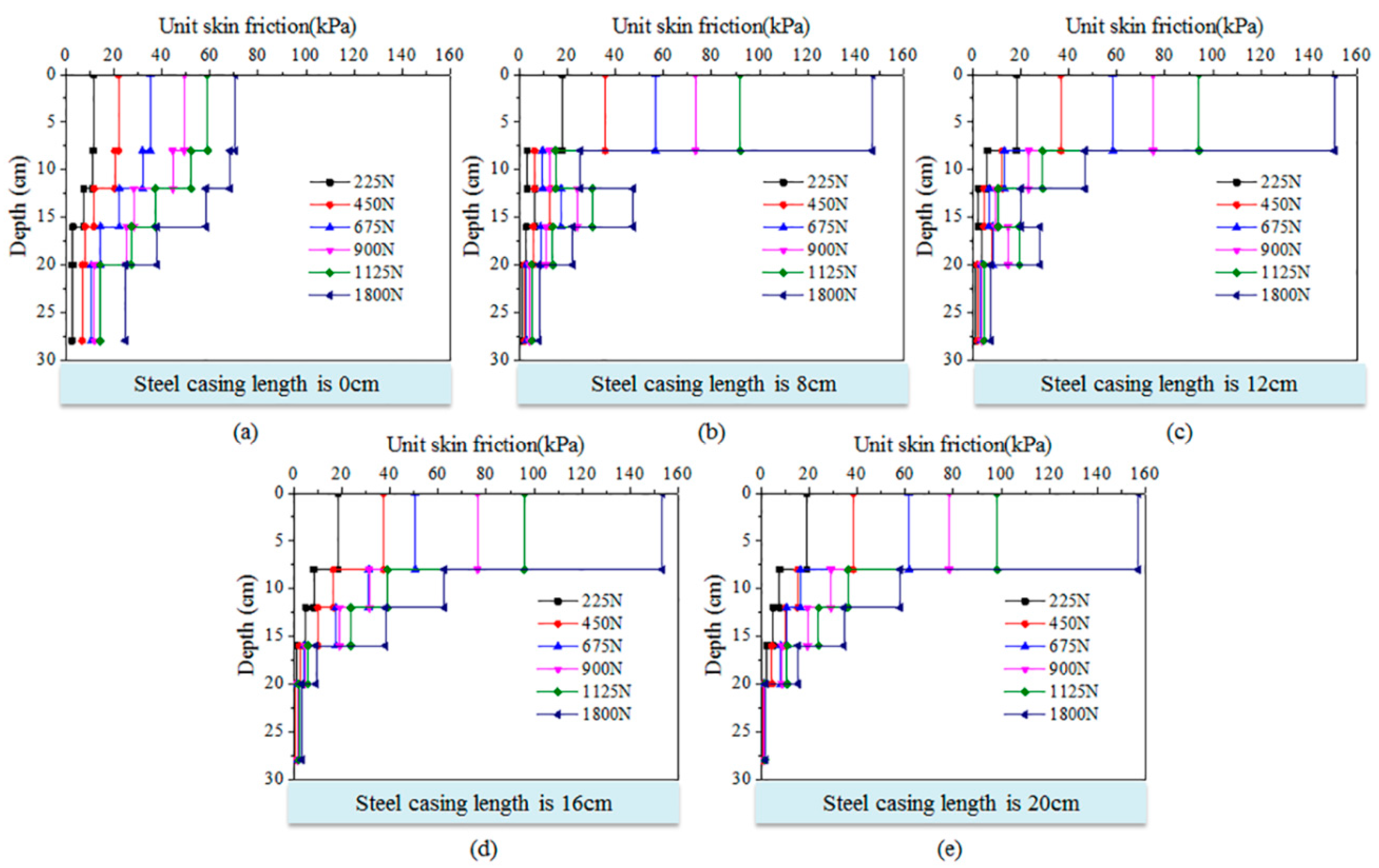
3.3. Effect of Steel Casing on Unit Skin Friction

Unit skin friction of the pile shaft can be obtained by Equation (6).
T = P i P i + 1 π Dh
where T is the unit skin friction of the pile; P i is the axial force of the pile, i is the number of strain gauges, 1~6 from top to bottom; D is the diameter of the pile; h is the distance between two adjacent strain gauges.
Unit skin friction of steel tube-reinforced concrete piles with different steel casing lengths is shown in Figure 13.
As shown in Figure 13b,c, when the steel casing length is 8 cm or 12 cm, the unit skin friction of steel tube-reinforced concrete piles will reduce first, then increase, and finally decrease. Between the upper steel casing section and the lower reinforced concrete section, a smaller value of the unit skin friction is generated, and the maximum unit skin friction of the upper steel casing section is significantly larger than the lower reinforced concrete section. The main reason is the downward and lateral extrusion of the soil at the end of the upper steel casing section, so that a relatively small pile-soil displacement appears near the junction of the upper steel casing section and the lower reinforced concrete section, so the unit skin friction of this part is small. As for the main part of the unit skin, the friction of the upper steel casing section is significantly larger than the lower reinforced concrete section; the reason is that the superficial area of the upper steel casing section is larger than that of the lower reinforced concrete section.
As shown in Figure 13d,e, when the steel casing length is 16 cm or 20 cm, the unit skin friction of steel tube-reinforced concrete piles will gradually reduce. Between the upper steel casing section and the lower reinforced concrete section, a smaller value of the unit skin friction is not generated. The main reason is that when the steel casing length is large, the lateral earth pressure at the end of the steel casing section is bigger [36], which will hinder the settlement and deformation of the soil at the end of the steel casing section; the upper steel casing section, the lower reinforced concrete section and the soil below the bottom of the steel casing section form a whole, hence the original unit skin friction of the smaller section will disappear.
As shown in Figure 13a, the maximum unit skin friction of the reinforced concrete pile without steel casing is smaller than that of steel tube-reinforced concrete piles. The main reason is that the diameter of the steel casing is slightly larger than the borehole size, which has extrusion effect on the soil, and with the increase of the length of the steel casing, the extrusion area of the steel casing and the soil increases, and more axial forces are transmitted to the soil in the form of shaft resistance.

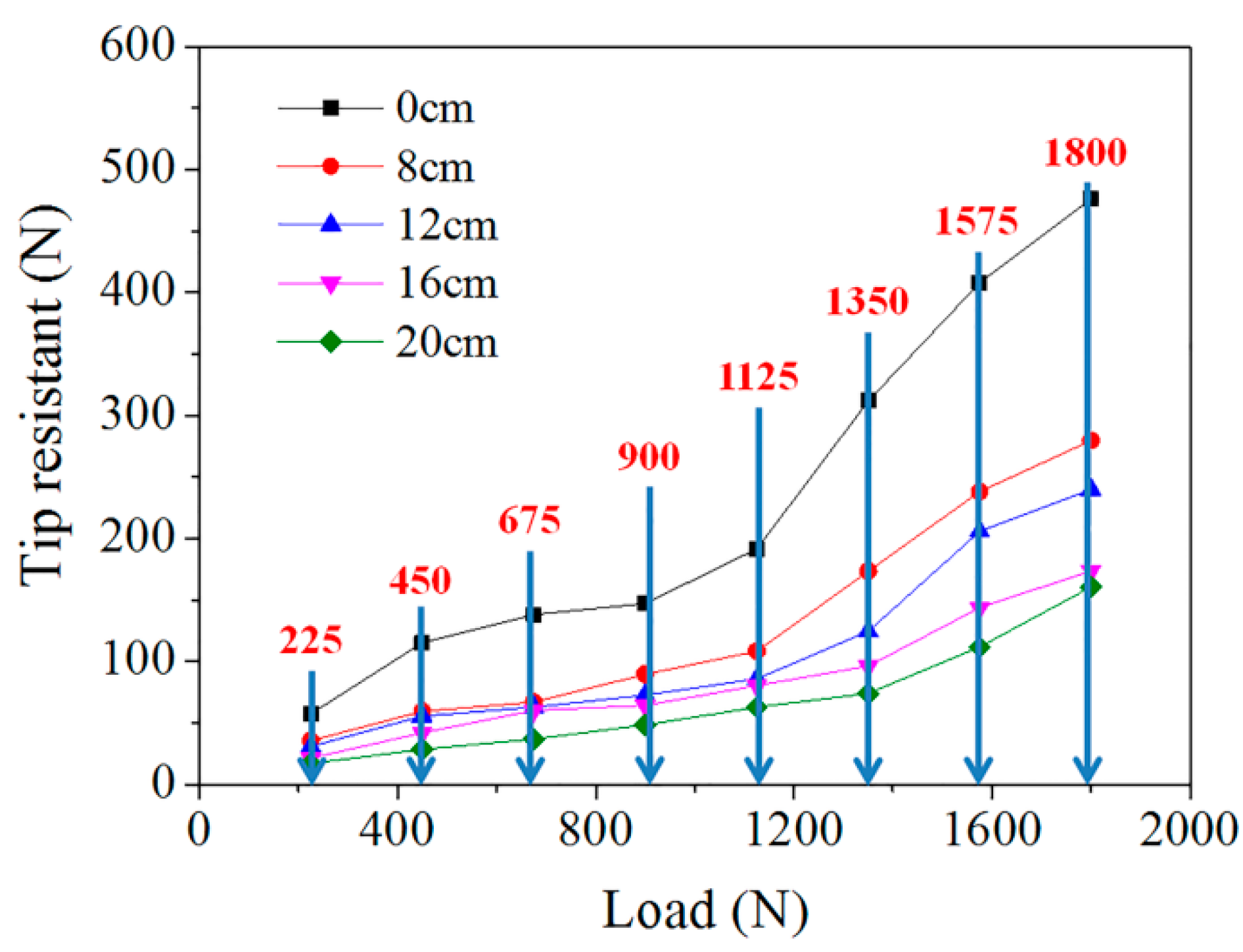
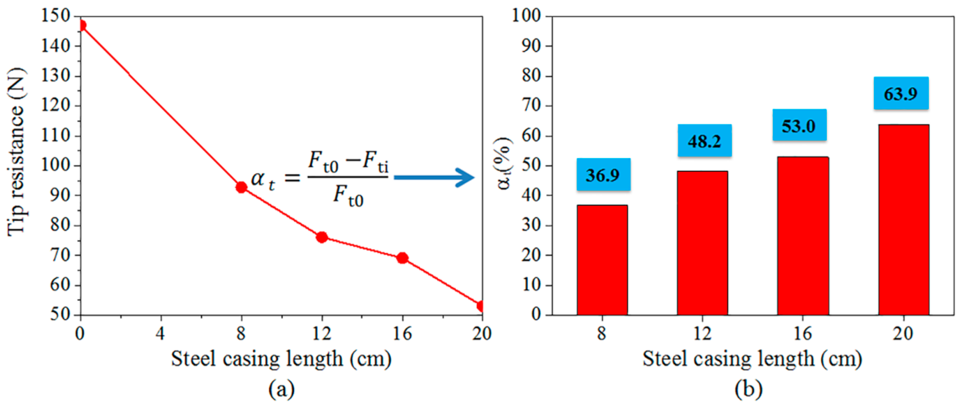
3.4. Effect of Steel Casing on Tip Resistance

Tip resistance of the pile can be obtained by earth pressure cell, which is installed at the bottom of the pile.
The effect of steel casing on the tip resistance of steel tube-reinforced concrete piles is shown in Figure 14.
As shown in Figure 14, the tip resistance of the pile increases gradually with the increase of pile top load; when the pile top load is small, the tip resistance of pile changes slowly; when the pile top load is large, the tip resistance of pile changes sharply. The main reason is that when the pile top load is small, the pile top load is mainly transmitted to the soil through the form of shaft resistance; when the pile top load exceeds a certain value, the shaft resistance has been fully utilized, and the pile top load will be transmitted to the soil mainly through the form of tip resistance [36]. In addition, the tip resistance of the pile without steel casing is larger than the steel tube-reinforced concrete piles with different steel casing lengths. The main reason is that pile top load is utilized through the form of shaft resistance and tip resistance; the shaft resistance of the pile without steel casing is smaller than the steel tube-reinforced concrete piles with different steel casing lengths, so the tip resistance of the pile without steel casing is larger than the steel tube-reinforced concrete piles. Moreover, the longer the steel casing is, the greater the shaft resistance is, and so the smaller the tip resistance is. In a word, the presence of steel casing will reduce the tip resistance of pile foundation.
The tip resistance under the ultimate bearing capacity will be further analyzed, as shown in Figure 15.
As shown in Figure 15, when the steel casing length is 0 cm, 8 cm, 12 cm, 16 cm, and 20 cm respectively, the tip resistance under the ultimate bearing capacity is 147.0 N, 92.8 N, 76.1 N, 69.1 N, and 53.0 N; the ratios of the tip resistance to the ultimate bearing capacity are 16.5%, 9.9%, 7.9%, 7.2%, and 5.5%. With the increase of steel casing length, the tip resistance of steel tube-reinforced concrete piles shows a gradual decreasing trend. The main reason is that the diameter of the steel casing is slightly larger than the borehole size, which has an extrusion effect on the soil, and with the increase of the length of the steel casing, the extrusion area of the steel casing and the soil increases, and the larger the shaft resistance that can be obtained. Because the bearing capacity is composed of shaft resistance and tip resistance, the tip resistance decreases as the length of the steel casing increases. When the steel casing length is 8 cm, 12 cm, 16 cm, and 20 cm respectively, the reduction rate of the tip resistance under the ultimate bearing capacity is 36.9%, 48.2%, 53.0%, and 63.9%, see Figure 15 and Equation (7). From the above research, it can be seen that the existence of steel casing will greatly reduce the tip resistance of piles.
α t = F t 0 F ti F t 0
where α t is the reduction rate of the tip resistance under the ultimate bearing capacity; F t 0 is the tip resistance of the conventional reinforced concrete pile; and F ti is the tip resistance of the steel tube-reinforced concrete piles with steel casing of 8 cm, 12 cm, 16 cm, and 20 cm.

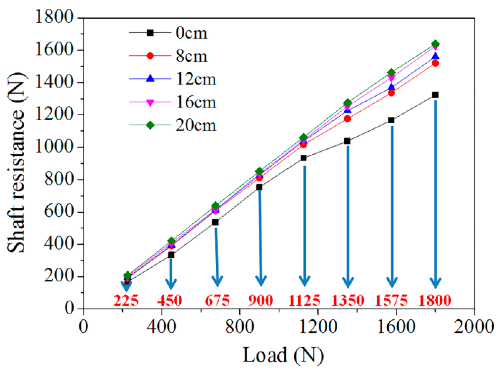
3.5. Effect of Steel Casing on Shaft Resistance

Shaft resistance of the pile shaft can be obtained by Equation (8).
Q s = Q u Q t
where Q s   is the shaft resistance of the pile; Q u is vertical loading of the pile; and Q t is the tip resistance of the pile.
The effect of steel casing on the shaft resistance of steel tube-reinforced concrete piles is shown in Figure 16.
As shown in Figure 16, the shaft resistance of the pile increases gradually with the increase of pile top load; when the pile top load is small, the shaft resistance of the pile increases linearly; when the pile top load is large, the increase of shaft resistance gradually slows down. The main reason is that when the pile top load increases gradually, the shaft resistance of the pile side gradually tends to limit. The shaft resistance of the pile without steel casing is smaller than steel tube-reinforced concrete piles with different steel casing lengths, which is due to the fact that the diameter of the steel casing is slightly larger than the borehole size, which has an extrusion effect on the soil, and with the increase of the length of the steel casing, the extrusion area of the steel casing and the soil increases, and more axial forces are transmitted to the soil in the form of the shaft resistance. In a word, the presence of steel casing can enhance the shaft resistance of the pile foundation.
The shaft resistance under the ultimate bearing capacity will be further analyzed, as shown in Figure 17.
As shown in Figure 17, when the steel casing length is 0 cm, 8 cm, 12 cm, 16 cm, and 20 cm respectively, the shaft resistance under the ultimate bearing capacity is 745.6 N, 845.0 N, 881.4 N, 895.5 N, and 915.2 N, and the ratios of the shaft resistance to the ultimate bearing capacity are 83.5%, 90.1%, 92.1%, 92.8%, and 94.5%. With the increase of steel casing length, the shaft resistance of steel tube-reinforced concrete piles shows a gradual increasing trend. The main reason is that the diameter of the steel casing is slightly larger than the borehole size, which has an extrusion effect on the soil, and with the increase of the length of the steel casing, the extrusion area of the steel casing and the soil increases, and the larger the shaft resistance that can be obtained. When the steel casing length is 8 cm, 12 cm, 16 cm, and 20 cm respectively, the lifting rate of the shaft resistance under the ultimate bearing capacity is 13.3%, 18.2%, 20.1%, and 22.7%, see Figure 17 and Equation (9). From the above research, it can be seen that the existence of steel casing will increase the shaft resistance of the piles. However, when the length of the steel casing exceeds 12 cm, the increase of the length of the steel casing has little effect on the shaft resistance.
α s = F si F s 0 F s 0
where α s is the lifting rate of the shaft resistance under the ultimate bearing capacity; F s 0 is the shaft resistance of the conventional reinforced concrete pile; and F si is the shaft resistance of the steel tube-reinforced concrete piles with steel casing of 8 cm, 12 cm, 16 cm, and 20 cm.

3.6. Advantages of Steel Casing in Pile Foundation Engineering

In this study, an increase of 8 m steel casing can increase 452 kN (ultimate bearing capacity) compared to conventional reinforced concrete piles without steel casing, equivalent to the gravity of 9.2 trucks whose quality is 5000 kg, in which it can be seen that the presence of steel casing can enhance the ultimate bearing capacity of the pile foundation.
In addition to the above advantage, steel casing has lots of other advantages. For example, it can position the pile, stabilize the borehole wall and so on.
Moreover, there are lots of loess caves and karst caves in China [37]. When a cave is encountered during an impact into a hole before forming a bored pile, if the cave is small and the leakage is less, it can be backfilled through the stone and clay, re-impact into the hole. If the cave is huge and the leak is serious, it is necessary to use a steel casing to clog the cave [38], as shown in Figure 18.
In a word, the steel casing is very beneficial to the pile foundation; it can not only improve the bearing capacity of the pile foundation, but also solve the slurry leakage problem of huge caves in the project. The most important point is to choose a reasonable length of steel casing according to the engineering needs.

4. Conclusions

The axial force of steel tube-reinforced concrete piles drops faster along the pile shaft than conventional reinforced concrete pile. The main reason is that as the length of the steel casing increases, more axial forces are transmitted to the soil through the form of shaft resistance.
When the length of steel casing is 8 cm or 12 cm, the unit skin friction of steel tube-reinforced concrete piles will reduce first, then increase, and finally decrease. When the length of steel casing is 16 cm or 20 cm, the unit skin friction of steel tube-reinforced concrete piles will gradually reduce.
The tip resistance of steel tube-reinforced concrete piles is smaller than a conventional reinforced concrete pile; the existence of steel casing will greatly reduce the tip resistance of piles.
The shaft resistance of steel tube-reinforced concrete piles is bigger than the conventional reinforced concrete pile; the existence of steel casing will increase the shaft resistance of piles. When the length of the steel casing exceeds 12 cm, the increase of the length of the steel casing has little effect on the shaft resistance.
The presence of steel casing can enhance the ultimate bearing capacity of the pile foundation. Moreover, it can solve the slurry leakage problem of huge caves in the project.

Author Contributions

Conceptualization, Z.F., H.H., and Y.D.; Data curation, H.H.; Formal analysis, H.H., Y.Z., and J.H.; Funding acquisition, Z.F.; Investigation, F.W., and M.J.; Methodology, H.H., F.W., and M.J.; Project administration, Z.F., Y.D., F.W., and M.J.; Resources, Z.F., and Y.D.; Software, H.H.; Supervision, H.H.; Validation, H.H.; Visualization, H.H.; Writing–original draft, H.H.; Writing–review & editing, Z.F., Y.D., Y.Z., and J.H.

Funding

This research was funded by National Natural Science Foundation of China (41272285); Traffic Science and Technology Projects in Guangdong Province (2011-01-001); Key Transportation Science and Technology Research Projects in Qinghai Province (2014-07); Traffic Science and Technology Projects in Hainan Province (HNZXY2015-045R).

Conflicts of Interest

The authors declare no conflict of interest.

References

  1. Lai, J.; Liu, H.; Qiu, J.; Fan, H.; Zhang, Q.; Hu, Z.; Wang, J. Stress analysis of CFG pile composite foundation in consolidating saturated mine tailings dam. Adv. Mater. Sci. Eng. 2016, 2016, 1–12. [Google Scholar] [CrossRef]
  2. Lai, J.; Liu, H.; Qiu, J.; Chen, J. Settlement analysis of saturated tailings dam treated by CFG pile composite foundation. Adv. Mater. Sci. Eng. 2016, 2016, 1–10. [Google Scholar] [CrossRef]
  3. Lai, J.; Mao, S.; Qiu, J.; Fan, H.; Zhang, Q.; Hu, Z.; Chen, J. Investigation progresses and applications of fractional derivative model in geotechnical engineering. Math. Probl. Eng. 2016, 2016, 9183296:1–9183296:15. [Google Scholar] [CrossRef]
  4. Duan, L.; Zhang, Y.; Lai, J. Influence of Ground Temperature on Shotcrete-to-Rock Adhesion in Tunnels: A Review. Adv. Mater. Sci. Eng. 2019, 2019, 8709087:1–8709087:12. [Google Scholar] [CrossRef]
  5. Zhou, Z.; Dong, Y.; Jiang, P.; Han, D.; Liu, T. Calculation of Pile Side Friction by Multiparameter Statistical Analysis. Adv. Mater. Sci. Eng. 2019, 2019, 2638520:1–2638520:12. [Google Scholar] [CrossRef]
  6. Zhang, Q.; Li, L.; Chen, Y. Analysis of compression pile response using a softening model, a hyperbolic model of skin friction, and a bilinear model of end resistance. J. Eng. Mech. 2014, 140, 102–111. [Google Scholar] [CrossRef]
  7. Zhang, Q.; Liu, S.; Zhang, S.; Zhang, J.; Wang, K. Simplified non-linear approaches for response of a single pile and pile groups considering progressive deformation of pile–soil system. Soils Found. 2016, 56, 473–484. [Google Scholar] [CrossRef]
  8. Zhang, Q.; Zhang, Z. A simplified nonlinear approach for single pile settlement analysis. Can. Geotech. J. 2012, 49, 1256–1265. [Google Scholar] [CrossRef]
  9. Lee, C.W.; Kim, Y.S.; Park, S.Y. Development of prebored screw pile method and evaluation of its bearing characteristics. Mar. Georesour. Geotec. 2016, 34, 42–56. [Google Scholar] [CrossRef]
  10. Zhou, J.; Gong, X.; Wang, K.; Zhang, R.; Yan, T. A model test on the behavior of a static drill rooted nodular pile under compression. Mar. Georesour. Geotec. 2016, 34, 293–301. [Google Scholar] [CrossRef]
  11. Sun, H.; Wang, Q.P.; Zhang, P.; Zhong, Y.J.; Yue, X.B. Spatiotemporal Characteristics of Tunnel Traffic Accidents in China from 2001 to Present. Adv. Civ. Eng. 2019, 4536414, 1–16. [Google Scholar] [CrossRef]
  12. Ai, Z.Y.; Chen, Y.F.; Jiang, X.B. Behavior of laterally and vertically loaded piles in multi-layered transversely isotropic soils. Appl. Math. Model 2017. [Google Scholar] [CrossRef]
  13. Aslani, F.; Uy, B.; Tao, Z.; Mashiri, F. Behaviour and design of composite columns incorporating compact high-strength steel plates. J. Constr. Steel Res. 2015, 107, 94–110. [Google Scholar] [CrossRef]
  14. Aslani, F.; Uy, B.; Tao, Z.; Mashiri, F. Predicting the axial load capacity of high-strength concrete filled steel tubular columns. Steel Compos. Struct. 2015, 19, 967–993. [Google Scholar] [CrossRef]
  15. Montuori, R.; Piluso, V. Analysis and modelling of CFT members: Moment curvature analysis. Thin Wall. Struct. 2015, 86, 157–166. [Google Scholar] [CrossRef]
  16. Lai, J.; Qiu, J.; Fan, H.; Zhang, Q.; Hu, Z.; Wang, J.; Chen, J. Fiber bragg grating sensors-based in situ monitoring and safety assessment of loess tunnel. J. Sensors 2016, 2016, 8658290:1–8658290:10. [Google Scholar] [CrossRef]
  17. Gaaver, K.E. Geotechnical properties of Egyptian collapsible soils. Alex. Eng. J. 2012, 51, 205–210. [Google Scholar] [CrossRef] [Green Version]
  18. Momeni, M.; Shafiee, A.; Heidari, M.; Jafari, M.K.; Mahdavifar, M.R. Evaluation of soil collapse potential in regional scale. Nat. Hazards 2012, 64, 459–479. [Google Scholar] [CrossRef]
  19. Kalantari, B. Foundations on collapsible soils: A review. Proc. Inst. Civil Eng-Frensic Eng. 2013, 166, 57–63. [Google Scholar] [CrossRef]
  20. Qian, Z.; Lu, X.; Yang, W.; Cui, Q. Behaviour of micropiles in collapsible loess under tension or compression load. Geomech. Eng. 2014, 7, 477–493. [Google Scholar] [CrossRef]
  21. Noorzad, R.; Pakniat, H. Investigating the effect of sample disturbance, compaction and stabilization on the collapse index of soils. Environ. Earth Sci. 2016, 75. [Google Scholar] [CrossRef]
  22. Gao, X.; Wang, J.; Zhu, X. Static load test and load transfer mechanism study of squeezed branch and plate pile in collapsible loess foundation. J. Zhejiang Univ-sci. A 2007, 8, 1110–1117. [Google Scholar] [CrossRef]
  23. Wang, L.; Sun, J.; Huang, X.; Xu, S.; Shi, Y.; Qiu, R.; Zhang, Z. A field testing study on negative skin friction along piles induced by seismic subsidence of loess. Soil Dyn. Earthq. Eng. 2011, 31, 45–58. [Google Scholar] [CrossRef]
  24. Zhang, Y.; Yao, Y.; Ma, A.; Liu, C. In situ tests on improvement of collapsible loess with large thickness by down-hole dynamic compaction pile. Eur. J. Environ. Civ. En. 2017, 1–15. [Google Scholar] [CrossRef]
  25. Xing, H.; Liu, L. Field tests on influencing factors of negative skin friction for pile foundations in collapsible loess regions. Int. J. Civ. Eng. 2018, 16, 1–10. [Google Scholar] [CrossRef]
  26. Zhou, Z.; Zhu, S.; Kong, X.; Lei, J.; Liu, T. Optimization Analysis of Settlement Parameters for Postgrouting Piles in Loess Area of Shaanxi, China. Adv. Civ. Eng. 2019, 2019, 7085104:1–7085104:11. [Google Scholar] [CrossRef]
  27. Naggar, M.H.E.; Sakr, M. Evaluation of axial performance of tapered piles from centrifuge tests. Can. Geotech. J. 2000, 37, 1295–1308. [Google Scholar] [CrossRef]
  28. Lee, M.; Bae, K.T.; Lee, I.W.; Yoo, M. Cyclic p-y Curves of Monopiles in Dense Dry Sand Using Centrifuge Model Tests. Appl. Sci. 2019, 9, 1641. [Google Scholar] [CrossRef]
  29. Im, E.S.; Kim, T.H. Lateral earth pressure acting on underground retaining structure in clay ground under embankment based on centrifuge model tests. KSCE J. Civ. Eng. 2004, 8, 387–396. [Google Scholar] [CrossRef]
  30. Jang, Y.S.; Kim, Y.S. Centrifugal model behavior of laterally loaded suction pile in sand. KSCE J. Civ. Eng. 2013, 17, 980–988. [Google Scholar] [CrossRef]
  31. Wang, C.; Zhou, S.; Guo, P.; Wang, B. Experimental analysis on settlement controlling of geogrid-reinforced pile-supported embankments on collapsible loess in high-speed railway. Int. J. Pavement Eng. 2014, 15, 867–878. [Google Scholar] [CrossRef]
  32. Wang, C.; Wang, B.; Guo, P.; Zhou, S. Experimental analysis on settlement controlling of geogrid-reinforced pile-raft-supported embankments in high-speed railway. Acta Geotech. 2014, 15, 231–242. [Google Scholar] [CrossRef]
  33. China Institute of Water Resources and Hydropower. Code of Geotechnical Centrifuge Model Tests; DL/T 5012-1999; CIWRH: Beijing, China, 1999. (In Chinese) [Google Scholar]
  34. Li, L.; Huang, J.; Han, B. Centrifugal Investigation of Excavation Adjacent to Existing Composite Foundation. J. Perform. Constr. Fac. 2018, 32. [Google Scholar] [CrossRef]
  35. Ministry of Housing and Urban-Rural Construction of the People’s Republic of China. Technical Code for Testing of Building Foundation Piles; JGJ106-2014; China Architecture & Building Press: Beijing, China, 2014.
  36. Ministry of Housing and Urban-Rural Construction of the People’s Republic of China. Chinese Technical Code for Building Pile Foundations; JGJ94-2008; China Architecture & Building Press: Beijing, China, 2008.
  37. Peng, J.; Li, X.; Fan, W.; Chen, Z.; Su, S.; Song, Y.; Lu, Q.; Deng, Y.; Chen, L.; Sun, P. Classification and development pattern of caves in the loess plateau. Earth Sci. Front 2007, 14, 234–244. (In Chinese) [Google Scholar] [CrossRef]
  38. Zhang, L.; Chen, J.; Qu, C. Analysis and discussion of several issues of pile foundation construction in karst region of Tangshan. Chin. J. Geotech. Eng. 2011, 33, 318–323. [Google Scholar]
Figure 1. TLJ-3 type geotechnical centrifuge.
Applsci 09 02874 g001
Figure 2. Model piles.
Applsci 09 02874 g002
Figure 3. Strain Gauges Layout diagram.
Applsci 09 02874 g003
Figure 4. Position of earth pressure cell.
Applsci 09 02874 g004
Figure 5. Tests: (a) Oedometer test; (b) Moisture content test; (c) Direct shear test.
Applsci 09 02874 g005
Figure 6. The main test procedures.
Applsci 09 02874 g006
Figure 7. The position of the model piles: (a) Planar graph; (b) A-A section diagram; (c) B-B section diagram.
Applsci 09 02874 g007
Figure 8. Vertical Loading device.
Applsci 09 02874 g008
Figure 9. Load–settlement curve.
Applsci 09 02874 g009
Figure 10. Effect of steel casing on ultimate bearing capacity: (a) Ultimate bearing capacity; (b) Lifting rate of ultimate bearing capacity.
Applsci 09 02874 g010
Figure 11. Lifting value of ultimate bearing capacity.
Applsci 09 02874 g011
Figure 12. Axial force of steel tube-reinforced concrete piles with different steel casing lengths: (a) Steel casing length is 0 cm; (b) Steel casing length is 8 cm; (c) Steel casing length is 12 cm; (d) Steel casing length is 16 cm; and (e) Steel casing length is 20 cm.
Applsci 09 02874 g012
Figure 13. Unit skin friction of steel tube-reinforced concrete piles with different steel casing lengths: (a) Steel casing length is 0 cm; (b) Steel casing length is 8 cm; (c) Steel casing length is 12 cm; (d) Steel casing length is 16 cm; and (e) Steel casing length is 20 cm.
Applsci 09 02874 g013
Figure 14. Effect of steel casing on tip resistance.
Applsci 09 02874 g014
Figure 15. Effect of steel casing on tip resistance under ultimate bearing capacity: (a) Tip resistance under the ultimate bearing capacity; (b) Reduction rate of tip resistance under ultimate bearing capacity.
Applsci 09 02874 g015
Figure 16. Effect of steel casing on shaft resistance.
Applsci 09 02874 g016
Figure 17. Effect of steel casing on shaft resistance under ultimate bearing capacity: (a) Shaft resistance under the ultimate bearing capacity; (b) Lifting rate of shaft resistance under ultimate bearing capacity.
Applsci 09 02874 g017
Figure 18. Engineering Application of Steel casing.
Applsci 09 02874 g018
Table 1. Similitude ratios in centrifugal model tests.
ParameterRatio
Length1∶n
Displacement1∶n
Diameter1∶n
Stress and strain1∶1
Area1∶n 2
Force1∶n 2
Note: Centrifugal acceleration = n g.
Table 2. Characteristics of test piles.
g LevelPile Length LOutside Diameter DThickness TYoung′s modulus E (GPa)
Model (mm)Proto-Type (m)Model (mm)Proto-Type (m)Model (mm)Proto-Type (m)
10035035252.520.263.3
Table 3. Characteristics of steel casing.
g LevelLength LOutside Diameter DThickness tYoung′s modulus E (GPa)
Model (cm)Proto-Type (m)Model (mm)Proto-Type (m)Model (mm)Proto-Type (m)
100202030320.2164
1616
1212
88
Table 4. Physical properties of loess.
NameDensity (g/cm3)Compressive Modulus (MPa)Moisture Content ω (%)Cohesion c (kPa)Internal Friction Angle φ (°)
Loess1.726.913.52721

