Abstract
The micro-displacement measurement system with 2D/3D has become increasingly important in the field of scientific research and technology application. In order to explore the application of an optical surface in micro-displacement measurement, a novel and simple 2D micro-displacement measurement method based on the elliptical paraboloid was designed and subjected to experiment. The measurement system takes advantage of the elliptical paraboloid instead of a plane mirror in the optical structure of an autocollimator which has been ameliorated to adapt to curved surface measurement. Through the displacement of the light spot on the CCD (Charge Coupled Device) detector, the displacement of the target could be measured with a linear correlation coefficient of 0.9999. The accuracy of the system is about ± 0.3 μm in a wide range in two dimensions. The results were in good agreement with the theoretical analysis and indicated the potential applicability of the proposed system in the detection of geometric errors of CNC (Computerized Numerical Control) machine tools.
1. Introduction
The measurement of micro angle and displacement plays an important role in science and technology [1,2]. Optical angle or displacement apparatuses have been applied in many fields, such as in the calibration of machine tools and the measurement of multi-degrees-of-freedom systems [3]. Under certain conditions, the principles of angle measurement are also applicable to displacement measurement. Conventionally, the three main optical methods for angle measurement with high resolution and accuracy are: interferometers, internal-reflection and autocollimators [4,5,6,7,8]. An interferometer utilizes phase information to measure angular and linear displacement with high signal-to-noise ratio and high resolution [9]. The internal-reflection effect can make a wide range of devices very stable and compact with high resolution [10]. An autocollimator is customarily used for measurement of straightness, flatness and angular position [11]. As mentioned, the principles of interferometry and internal-reflection have been transformed into the displacement measurement field [12,13,14,15]. However, seldom has the autocollimator principle been studied in the field of displacement measurement. Compared with the other two methods, displacement measurement based on the autocollimator principle has important application value, especially in two-dimensional displacement measurement, which is worth researching. In reality, an interferometer is usually large in size with a high cost in many applications [16]. Moreover, the displacement measurement based on internal-reflection is limited by the measurement range, the geometric accuracy of the reflection prisms, and material inhomogeneity [17]. For example, Gao developed a two-axis position measurement using an optical slope sensor based on an autocollimator with a resolution of 0.1 μm, with a low cost and a small size [18]. In addition, with the development of optical surface processing technology, the application of an optical freeform surface has become more and more extensive [19]. For instance, Gao realized the nanometer scale measurement of two-dimensional displacement based on an optical freeform surface with a double sinusoid [20,21]. The space wavelength of the sinusoid was 150 μm and the amplitude was 100 nm. However, a nonlinear error is generated by using the superimposed sinusoid freeform surface as the reference element of the displacement measurement. Therefore, it is necessary to design a novel optical freeform surface element to realize linear transformation of angle and displacement for micro-displacement measurement, which we refer to as the elliptical paraboloid.
In this paper, a novel two-dimensional micro-displacement measurement method based on the elliptical paraboloid is proposed. The elliptical paraboloid device is the key to realizing the transformation of angle to displacement. The basic optical structure of an autocollimator is slightly improved to accommodate the measurement of the curved surface. The experimental results show that the principle of an autocollimator is applicable to micro-displacement and linear measurement, and that two-dimensional displacement can be measured simultaneously with an accuracy within ± 0.3 μm. Although some aspects need to be improved, this measurement has a good range of application, such as the detection of geometric errors of CNC machine tools.
2. System and Principle
2.1. System Configuration
The schematic of the 2D micro-displacement measurement system based on the elliptical paraboloid is shown in Figure 1. A collimated laser beam generated from a signal-mode laser source (power 5 mW, wavelength λ = 650 nm, unpolarized light, laser diode) passes through the aperture and lens 1 into the polarizing beam splitter (PBS) with a reflection factor of 50%. The role of the aperture (diameter 300 μm) is to control the diameter of the beam to eliminate the influence of non-measurable light and the function of lens 1 (focal length f1 = 30 mm) is to converge the beam to obtain an excellent light spot image. After passing through the PBS, the laser beam, which has been converted into a linear polarized beam, travels through a quarter wave plate to the elliptical paraboloid. The function of the quarter wave plate is to convert the linear polarized beam into a circle-polarized beam. When the beam is reflected back to the quarter wave plate again, its polarized direction is rotated by 90° so that it can travel back to the PBS. Then, the surface of the elliptical paraboloid reflects the laser beam, whose function is similar to the plane mirror in the structure of an autocollimator. The elliptical paraboloid can realize the linear transformation of angle and displacement, so the displacement can be processed according to the principle of angle measurement. Finally, the reflected beam reaches lens 2 (focal length f2 = 100 mm), acting as an objective lens and being focused by lens 2 on a CCD detector (pixels number 2592 × 1944, pixel size 2.2 μm × 2.2 μm) located on the focal plane of lens 2, which is linked to a personal computer. The displacement of the object can be calculated using the computer processing results for the displacement of the light spot. In fact, 2D displacement can be magnified so as to be measured using characteristics of the elliptical paraboloid. The magnification factor is determined by the parameter of the elliptical paraboloid and the focal length of lens 2.
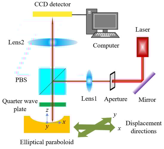
Figure 1.
Schematic of the measurement system.
2.2. Measurement Principle
The basic element of the measurement system is the elliptical paraboloid, which is shown in Figure 2. The elliptical paraboloid was micromachined by an ultraprecision diamond tool using brass (H62) as the original material. Through the feedback loop between precise machining and inspection, the elliptical paraboloid was processed successfully. Its processing quality was detected by 3D Surface Measuring System (LuphoScan, Taylor Hobson, UK) and the result shows that the RMS is 0.021 μm. It takes 3 h of skilled labor to produce such a part. Of course, the machining time depends on the size and quantity of the elliptical paraboloid. Here, its mouth diameter is 10 mm. In reality, it can be scaled up to a large volume (mouth diameter 50 mm). Nevertheless, the measurement range will limit its unnecessary volume. A Cartesian coordinate system is established in the vertex of the elliptical paraboloid. It is assumed that the equation of the elliptical paraboloid is
where a is the parameter of the elliptical paraboloid. The derivatives of Equation (1) in the direction of x and y are calculated as follows, respectively:
where is the angle between the tangent of the point on the elliptical paraboloid and the x direction, and is the angle between the tangent of the point on the elliptical paraboloid and the y direction. According to the above equations, the relationship between the displacement on the elliptical paraboloid and the tangent of the angle is linear.
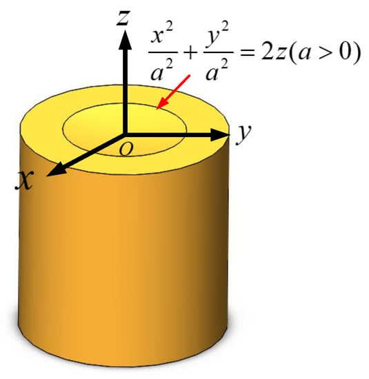
Figure 2.
Model of the elliptical paraboloid.
The measurement system based on the elliptical paraboloid utilizes the optical autocollimator principle to obtain a 2D micro-displacement variation, as shown in Figure 3. The measurement system is similar to the typical optical autocollimator system except that the plane mirror is replaced by an elliptical paraboloid. The measuring beam propagating along the horizontal direction is reflected by the elliptical paraboloid, which is received by a CCD detector after being focused by lens 2 with focal length . While the measuring beam moves along the direction, the reflected beam converges on another point on the CCD detector. Supposing that the angle between the tangent at the measuring point and the vertical direction is and the displacement of the light spot on the CCD detector is , the following equation can be obtained:
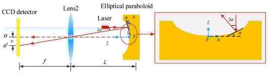
Figure 3.
Measurement principle based on autocollimation.
Generally speaking, the angle is especially small. According to Equation (2) and (4), the following result can be obtained, which shows the relationship between the displacement of the measuring beam in the x direction and the displacement of the light spot on the CCD detector:
Similarly, the relationship between the displacement of the measuring beam in the y direction and the displacement of the light spot on the CCD detector can be easily written as follows:
From Equations (5) and (6), the linear relationship between the displacement of the laser beam and the light spot can be utilized to measure micro-displacement.
2.3. Light Spot Image Processing
The image of the light spot obtained by the CCD detector is shown in Figure 4. After a series of digital image processing operations, including extraction of the region of interest (ROI) and filtering, the gray centroid algorithm was applied to the light spot on the image and can be expressed as
where is the pixel coordinate, is the image size, is the gray value of the pixel and is the centroid coordinate to be used.
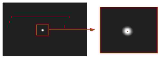
Figure 4.
Image of the light spot.
In order to improve the stability of the measurement system, a median filtering algorithm based on statistical ranking principle was applied. A queue with a length of seven was designed. When new data enter the head of the queue, the old data located at the tail of the queue are removed. Meanwhile, the median of the data in the queue will be calculated as the value presented at the current spot location. The experimental results show that the median filtering algorithm makes the system stable within ± 0.05 pix for 4 h.
3. Experimental Results
To verify the feasibility and accuracy of the measurement method, a series of experiments were carried out under laboratory conditions. Figure 5 shows the experimental configuration used for the micro-displacement measurement system in the direction.
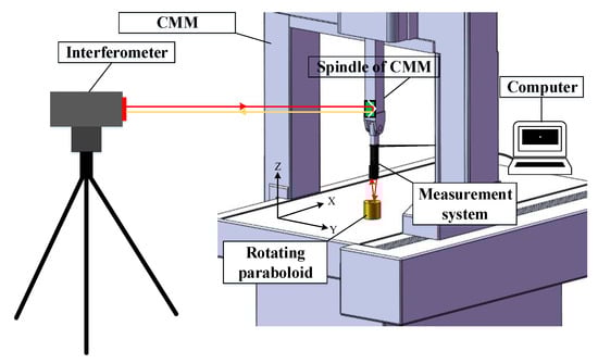
Figure 5.
Experimental configuration in the x direction.
3.1. Calibration Experiments
The relationship between the displacement to be measured and the displacement of the light spot detected by the CCD detector in two directions was required to calibrate the experiments. The coordinate-measuring machines (CMM) (Hexagon, Stockholm, Sweden) and a Renishaw XL80 (Renishaw, Gloucestershire, UK) laser measurement system were used in the calibration experiments. The experiments in two directions were repeated several times, and the results are shown in Figure 6 and Figure 7. Figure 6 shows the calibration result in the x direction, from which we can work out that the relationship between the measured displacement and the relative displacement of the light spot is . Furthermore, the linear correlation coefficient R2 is 0.9999. Figure 7 shows the result obtained from the y direction calibration experiments. It can be seen from Figure 7 that the relationship between the measured displacement and the relative displacement of the light spot is , and the linear correlation coefficient R2 equals 0.9999.
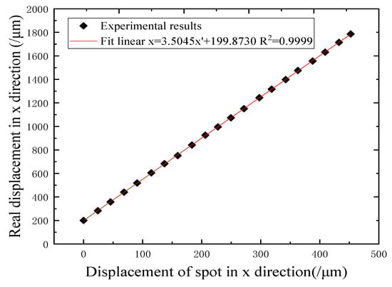
Figure 6.
Calibration results in the x direction.
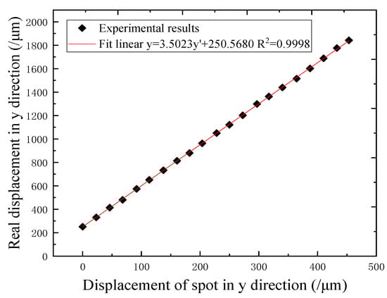
Figure 7.
Calibration results in the y direction.
3.2. Comparison Experiments
The comparison experiments aim to verify the accuracy of the two-dimensional micro-displacement measurement system. A Renishaw XL80 laser measurement system was used for the comparison experiments, and its displacement resolution was 0.1 μm. The displacement of the CMM spindle carrying the measuring system was detected by Renishaw XL80, which was compared with the results from the measuring system. The comparison results for the two directions are shown in Figure 8 and Figure 9, in which the red straight line is the linear fitting of black squares representing the comparative data. The horizontal axis represents the readings of the XL80 laser measurement system, and the vertical axis represents the displacement coming from the proposed measured system, which is translated from the displacement of the light spot. The fitting correlation R2 value is 0.9999 in Figure 8, whereas the fitting correlation R2 value shown in Figure 9 is 0.9999. Obviously, the two systems indicate very good agreement in the x and y directions. Moreover, the residuals between our system and the XL80 laser system are within ± 0.3 μm in the x direction and also within ± 0.3 μm in the y direction. These are shown in the following figures as red stars.
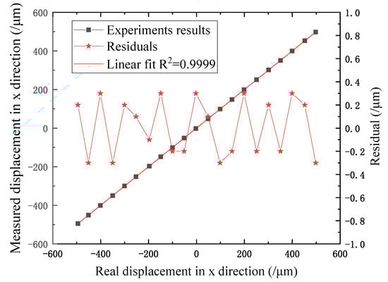
Figure 8.
Comparison results in the x direction.
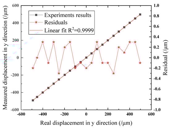
Figure 9.
Comparison results in the y direction.
4. Discussion
4.1. Manufacturing Error of the Elliptical Paraboloid
Several factors influence the accuracy of the 2D displacement measurement system. The first error that needs to be considered is the manufacturing error relating to the surface of the elliptical paraboloid, which has a major impact on the measurement system. The surface profile of the elliptical paraboloid is measured by an optical 3D surface profiler, and a parabola is selected from the test results to fit the quadratic curve. The fitting results of parabola and the fitting error are shown in Figure 10 and Figure 11. As can be seen from Figure 10 and Figure 11, the measured data are parabolic and can be effectively fitted by quadratic curves with a fitting error within ± 0.3 μm in the range of 80 μm height.
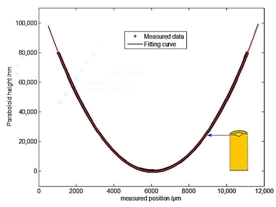
Figure 10.
Parabola measured data and fitting results.
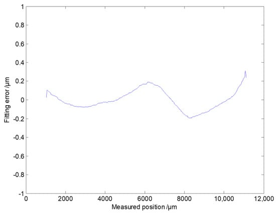
Figure 11.
Parabola fitting error.
In order to verify all of the processing characteristics of the elliptical paraboloid, several parabolas passing through its vertex in four different directions were selected and fitted in this paper. The fitting results are shown in Table 1. According to Table 1, the elliptical paraboloid has ideal processing precision because the quadratic coefficient () of each parabola has high repeatability. It is worth mentioning that these quadratic coefficients are consistent with the design value of 0.0032.

Table 1.
Fitting results of multiple parabola.
The perfect processing quality of the elliptical paraboloid is the basis and key aspect of micro-displacement. Therefore, high machining accuracy of the elliptical paraboloid in the manufacturing process is required, and its cleanness needs to be guaranteed in the measurement conditions.
4.2. Other Errors
The commercial off-the-shelf optical components are another error source which include the location error and the machining error. The location error, which was the CCD detector displacing off the focal plane, resulted in the deviation of the measurement system from the ideal value. The angle measuring error, caused by the CCD detector displacing off the focal plane and the reflection angle, is shown in Figure 12. Although the error is relatively small, it cannot be ignored. Of course, the error caused by location can be partly eliminated by the calibration experiment. Optical components are difficult to change once they are selected; therefore, we need to select high-quality components and pay careful attention in order to preserve them.
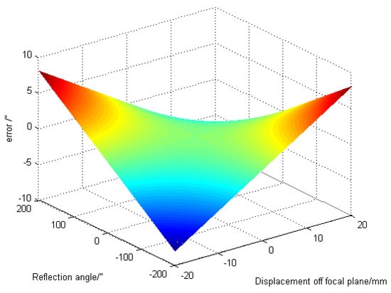
Figure 12.
Error caused by displacement off the focal plane.
The electronic noise of the CCD detector, the instability of the light spot and the environmental turbulence caused the drifting of the spot image. As mentioned above, the median filtering algorithm for the centroid of the spot image has the ability to solve this problem. However, higher precision measurement would demand higher requirements for the quality of the laser source and for the temperature and humidity of the controlled laboratory environment.
4.3. Future Research
In this paper, the research of 2D displacement measurement based on a single elliptical paraboloid was introduced. Compared with displacement measurement based on internal-reflection, the system proposed had the advantages of better measurement range in two-dimensions. In addition, the system developed was easy to set up and adjust within a short time period and at low cost in normal application, compared to interferometers. Although its measurement range was shorter than that of an interferometer, many methods could be used to solve this shortcoming. In order to improve the measurement range and application field of 2D displacement measurement, future research must focus on the calibration and measurement of the elliptical paraboloid array. The elliptical paraboloid array has great potential in measuring geometric errors of CNC machine tools, which contain positioning errors, straightness errors and perpendicularity errors. It will provide a new tool for understanding and measuring the geometric errors of CNC machine tools.
5. Conclusions
A novel and simple approach to 2D micro-displacement measurement based on the elliptical paraboloid was developed and tested. The main innovation of the measurement system was that it took advantage of the characteristics of the elliptical paraboloid, from which the displacement varies linearly with the angle in two directions. The designed optical configuration was effective regarding surface measurement and provided a high-quality light spot image. To verify the feasibility and accuracy of the measurement system, a series of experiments were carried out, and the results show that the displacement of the system is linearly related to the displacement of the light spot obtained by the CCD detector, which is consistent with the theoretical analysis. The measurement linearity was 0.9999 with an error of ± 0.3 μm compared with the Renishaw XL80 laser measurement system. In order to improve the measurement accuracy, manufacturing and installation errors of components need to be reduced, and the carefulness of the experimenters needs to be improved.
Author Contributions
F.F. and X.L. proposed the method and modified the paper; Z.L. designed the experiments and wrote the paper; D.Z., X.Y. and J.L. developed the system software and processed the data; Z.S. and H.L. designed the mechanical and optical structure.
Funding
This research was financially supported by the National Natural Science Foundation of China (NSFC) (No: 51775378) and the National Key R&D Program of China (No. 2017YFF0108102).
Conflicts of Interest
The authors declare no conflict of interest.
References
- Tan, X.R.; Zhu, F.; Wang, C.; Yu, Y.; Shi, J.; Qi, X.; Yuan, F.; Tan, J.B. Two-Dimensional Micro-/Nanoradian Angle Generator with High Resolution and Repeatability Based on Piezo-Driven Double-Axis Flexure Hinge and Three Capacitive Sensors. Sensors 2017, 17, 2672. [Google Scholar]
- Jywe, W.Y.; Hsieh, T.H.; Chen, P.Y.; Wang, M.S. An Online Simultaneous Measurement of the Dual-Axis Straightness Error for Machine Tools. Appl. Sci. 2018, 8, 2130. [Google Scholar] [CrossRef]
- Hsieh, T.H.; Chen, P.Y.; Jywe, W.Y.; Chen, G.W.; Wang, M.S. A Geometric Error Measurement System for Linear Guideway Assembly and Calibration. Appl. Sci. 2019, 9, 574. [Google Scholar] [CrossRef]
- Ikram, M.; Hussain, G. Michelson interferometer for precision angle measurement. Appl. Opt. 1999, 38, 113–120. [Google Scholar] [CrossRef] [PubMed]
- Chatterjee, S.; Kumar, Y.P. Measurement of two-dimensional small angle deviation with a prism interferometer. Appl. Opt. 2008, 47, 4900–4906. [Google Scholar] [CrossRef]
- Zhou, W.; Cai, L. Interferometer for small-angle measurement based on total internal reflection. Appl. Opt. 1998, 37, 5957–5963. [Google Scholar] [CrossRef]
- Yuan, J.; Long, X. CCD-area-based autocollimator for precision small-angle measurement. Rev. Sci. Instrum. 2003, 74, 1362–1365. [Google Scholar] [CrossRef]
- Chen, Y.T.; Huang, Y.S.; Liu, C.S. An Optical Sensor for Measuring the Position and Slanting Direction of Flat Surfaces. Sensors 2016, 16, 1061. [Google Scholar] [CrossRef]
- Heikkinen, V.; Byman, V.; Palosuo, I. Interferometric 2D small angle generator for autocollimator calibration. Metrologia 2017, 54, 253–261. [Google Scholar] [CrossRef]
- Liu, Y.; Kuang, C.; Ku, Y. Small angle measurement method based on the total internal multi-reflection. Opt. Laser Technol. 2012, 44, 1346–1350. [Google Scholar] [CrossRef]
- Li, K.; Kuang, C.; Liu, X. Small angular displacement measurement based on an autocollimator and a common-path compensation principle. Rev. Sci. Instrum. 2013, 84, 015108. [Google Scholar] [CrossRef] [PubMed]
- Martincek, I.; Kacik, D. A PDMS microfiber Mach-Zehnder interferometer and determination of nanometer displacements. Opt. Fiber Technol. 2018, 40, 13–17. [Google Scholar] [CrossRef]
- Lee, J.; Park, S.; Seo, D.H. Displacement measurement using an optoelectronic oscillator with an intra-loop Michelson interferometer. Opt. Express 2016, 24, 21910. [Google Scholar] [CrossRef] [PubMed]
- Wang, S.; Chiu, M.; Chen, W. Small-displacement sensing system based on multiple total internal reflections in heterodyne interferometry. Appl. Opt. 2009, 48, 2566–2573. [Google Scholar] [CrossRef] [PubMed]
- Lin, J.L.; Lee, X.X.; Hsieh, M.C.; Chang, C.O. High-angular-sensitivity total-internal-reflection heterodyne interferometry for micro-displacement measurements. Sens. Actuators A Phys. 2018, 277, 163–168. [Google Scholar] [CrossRef]
- Hsu, C.; Chen, H.; Tseng, H.; Lan, S.; Lin, J. High displacement resolution encoder by triple grating combination interferometer. Opt. Laser Technol. 2018, 105, 221–228. [Google Scholar] [CrossRef]
- Ku, Y.; Kuang, C.; Luo, D. Differential internal multi-reflection method for nano-displacement measurement. Opt. Lasers Eng. 2012, 50, 1445–1449. [Google Scholar] [CrossRef]
- Gao, W.; Dejima, S.; Shimizu, Y.; Kiyono, S. Precision Measurement of Two-Axis Position and Tilt Motions Using a Surface Encoder. CIRP Ann.-Manuf. Technol. 2013, 52, 435–438. [Google Scholar] [CrossRef]
- Fang, F.Z.; Zhang, X.D.; Weckenmann, A.; Zhang, G.X.; Evans, C. Manufacturing and Measurement of Freeform Optics. CIRP Ann.-Manuf. Technol. 2013, 62, 823–846. [Google Scholar] [CrossRef]
- Gao, W.; Araki, T.; Kiyono, S. Precision nano-fabrication and evaluation of a large area sinusoidal grid surface for a surface encoder. Precis. Eng. 2003, 27, 289–298. [Google Scholar] [CrossRef]
- Gao, W.; Kimura, A. A Three-axis Displacement Sensor with Nanometric Resolution. CIRP Ann.-Manuf. Technol. 2007, 56, 529–532. [Google Scholar] [CrossRef]


© 2019 by the authors. Licensee MDPI, Basel, Switzerland. This article is an open access article distributed under the terms and conditions of the Creative Commons Attribution (CC BY) license (http://creativecommons.org/licenses/by/4.0/).