A Design of a Lightweight In-Vehicle Edge Gateway for the Self-Diagnosis of an Autonomous Vehicle

1
Department of Computer Engineering, Catholic Kwandong University, Gangneung 25601, Korea
2
Department of Regional Economics, Kangwon National University, Samcheok 25913, Korea
*
Author to whom correspondence should be addressed.
Appl. Sci. 2018, 8(9), 1594; https://doi.org/10.3390/app8091594
Submission received: 8 August 2018
/
Revised: 22 August 2018
/
Accepted: 6 September 2018
/
Published: 9 September 2018
(This article belongs to the Special Issue Fault Detection and Diagnosis in Mechatronics Systems)
Abstract
:This paper proposes a Lightweight In-Vehicle Edge Gateway (LI-VEG) for the self-diagnosis of an autonomous vehicle, which supports a rapid and accurate communication between in-vehicle sensors and a self-diagnosis module and between in-vehicle protocols. A paper on the self-diagnosis module has been published previously, thus this paper only covers the LI-VEG, not the self-diagnosis. The LI-VEG consists of an In-Vehicle Sending and Receiving Layer (InV-SRL), an InV-Management Layer (InV-ML) and an InV-Data Translator Layer (InV-DTL). First, the InV-SRL receives the messages from FlexRay, Control Area Network (CAN), Media Oriented Systems Transport (MOST), and Ethernet and transfers the received messages to the InV-ML. Second, the InV-ML manages the message transmission and reception of FlexRay, CAN, MOST, and Ethernet and an Address Mapping Table. Third, the InV-DTL decomposes the message of FlexRay, CAN, MOST, and Ethernet and recomposes the decomposed messages to the frame suitable for a destination protocol. The performance analysis of the LI-VEG shows that the transmission delay time about message translation and transmission is reduced by an average of 10.83% and the transmission delay time caused by traffic overhead is improved by an average of 0.95%. Therefore, the LI-VEG has higher compatibility and is more cost effective because it applies a software gateway to the OBD, compared to a hardware gateway. In addition, it can reduce the transmission error and overhead caused by message decomposition because of a lightweight message header.
1. Introduction
In the future, more than 200 billion devices will be connected to the cloud and each other in what is commonly called the Internet of Things (IoT) [1]. Therefore, An IoT gateway that is a physical device or software program as the connection point between the cloud and controllers, sensors and intelligent devices plays important role. IoT gateway provides a place to preprocess the data located at the edge before sending it on to the cloud and supports communication between heterogeneous devices.
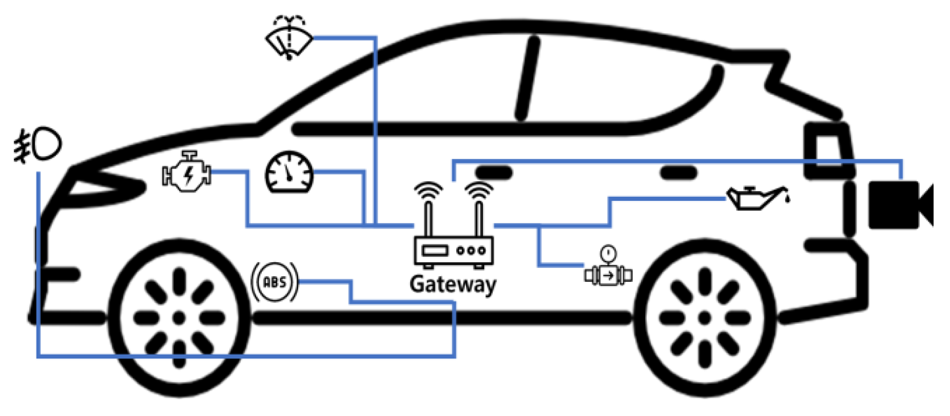
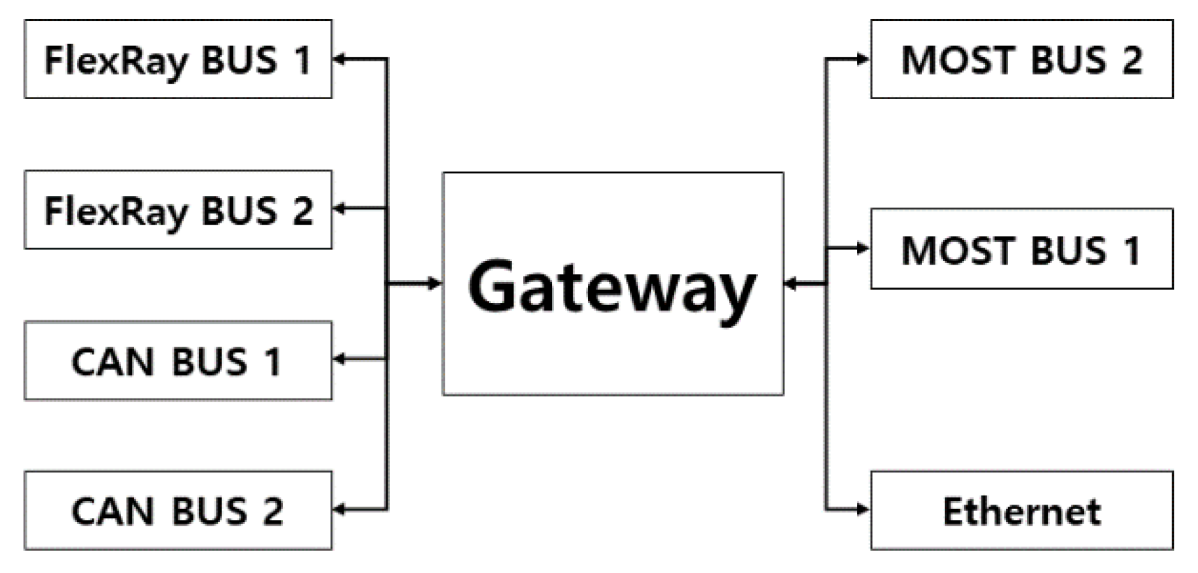
The gateways of connected cars, which are currently being developed, are similar to IoT gateways. As shown in Figure 1, the connected car’s ECUs and Gateway need to handle many requirements, such as enhancing engine control and transmission control performance; securing stability through ABS, LDW, and FCW; and increasing convenience through camera and body control. To address these needs, the number of ECUs used in vehicles has increased dramatically and ECUs are connected to various protocols depending on their characteristics [2].
To process such a large amount of data, various communication protocols such as FlexRay, MOST, CAN and Ethernet are used inside the vehicle. CAN, a low-speed (1 Mbps) communication protocol used in conventional in-vehicle communications, is used to process relatively less important vehicle control sensor data. FlexRay, a high-speed (10 Mbps) communication protocol, is mainly used to process control data of major parts of a vehicle. MOST and Ethernet have speeds up to 150 Mbps. MOST is a ring type network that processes multimedia data such as voice and video inside the vehicle, and Ethernet can be used as a backbone of in-vehicle network or as a V2X communication protocol.
To support these protocols, there have been various studies on the gateway inside the vehicle. However, gateways with minimum transmission delay only support some protocols such as CAN to FlexRay and MOST to CAN, and gateways that support communication for all protocols had increased transmission delay.
To support the four major protocols (i.e., CAN, FlexRay, MOST, and Ethernet) used for in-vehicle communications and to minimize the transmission delay of gateways, this paper proposes a Lightweight In-Vehicle Edge Gateway (LI-VEG) for the self-diagnosis of an autonomous vehicle. The LI-VEG receives the messages from the source sensor or actuator, translates the received messages into the format of a destination protocol, and transfers the translated messages to the destination ECU, sensor, or actuator, and the messages received from a source to the self-diagnosis module. Because the LI-VEG supports four major protocols, contrary to the existing vehicle gateway, it has good scalability and compatibility. In addition, The LI-VEG is indispensable to self-diagnosis module of an autonomous vehicle due to its rapidity and accuracy. A paper on the self-diagnosis module has already been published [3], thus this paper only covers the LI-VEG, not the self-diagnosis.
The remainder of the paper is organized as follows. In Section 2, related works are introduced. In Section 3, the configuration and operation of LI-VEG are described. In Section 4, the performance evaluation focuses in particular on the transmission delay and error rate for message transmission. Finally, Section 5 presents the conclusions of the paper.
2. Related Works
2.1. On-Board Diagnostics
Onboard-diagnostic (OBD) is an automotive term for self-diagnosis and reporting of vehicles. OBD system is developed to detect engine operation conditions for air-pollution monitoring [4]. The basic meaning of OBD is as above and it is used in various ways. OBD related research is as follows.
Configuration of on-board diagnostics system and diagnostic communication module ELM327 are introduced. According to elements of ELM327 and Keyword 2000 protocols, an OBDII diagnostic procedure is developed based on LabVIEW program [5].
Ochs. T. et al. [6] developed exhaust gas sensors for particulate matter (EGS-PM) based on multilayer ceramic sensor technology. Sensors must be able to detect soot emissions directly after the DPF, be able to withstand harsh exhaust gas environments, and meet future OBD legislation that includes stricter requirements for monitoring the function of the filter.
Kamimoto. T. et al. [7] reviewed currently soot sensors developed for on-board diagnostics to monitor a diesel particulate filter and detect the failure. Original equipment manufacturers have selected a resistive soot sensor for the on-board diagnostics application because of its commercial feasibility in terms of functionality and cost. The sensor accumulates soot particles in exhaust gas on the sensing element.
As powertrains become more electric, the number of on-board diagnostics relevant to Electronic Control Units (ECUs) continues to grow. Vector provides a summary of the on-board diagnostics functions integrated in the AUTOSAR basic software (BSW) and which use cases they support [8].
Mobile communication offers one-way data collection for remote surveillance when data transmission is continuously linked with server through mobile communication. Data acquisition is handled by on-board unit via EV CAN network. However, on-line data size, e.g., state of health, is so huge that it is not easily transmitted when hundreds of vehicles are simultaneously connected for data logging into server. Taking SOH as example, it is a challenge to effectively provide the continuity of curve variation for remote health estimation. Hence, estimation theory is applied and embedded into hardware implementation before data reporting [9].
Every vehicle will be equipped with a central unit which will acquire speed data (and compute the average speed) from the on-board sensors of a car using an OBD device, and process and deliver the data to the server using the ZigBee protocol, with a ZigBee transmitter employed in every vehicle and the receivers mounted on light poles. These receivers then route the received traffic information to a localized server shared by several junctions or clusters [10].
OBD a critical tool used for emission control in today’s automobiles. OBD generates fault codes when any system/component non-compliance is detected. Commercially available tools fetch fault codes from OBD and are providing only limited information/access of basic data to engineers. These tools are black box type of tools which provide very limited flexibility. In addition, the data storage capacity of these diagnostic tools is very limited. Next, we review the related study of OBD-II, which is the next version of OBD [11].
The extraction of all the available data in EV CAN network has been done systematically through OBD-II port and by using low-level software libraries and programming a development board based on ARM STM32F103RBT6 micro-controller [12].
An OBD II reader is designed to measure speed and mass air flow, from which the distance and fuel consumption are also computed. These data are then transmitted via WiFi to a remote server. The system also implements global positioning system tracking to determine the location of the vehicle. A database management system is implemented at the remote server for the storage and management of transmitted data and a graphical user interface is developed for analyzing the transmitted data [13].
One of the key issues enabling future solutions is achieving an effective integration between mobile apps and vehicles. Such integration can be efficiently achieved on all existing vehicles by relying on the OBD-II interface. This allows obtaining critical information such as speed, fuel consumption, gas emissions and system failures [14].
Tsai, Y.C. et al. [15] proposed an on-board safe driving assist system using vehicle dynamics and real-time traffic information. It immediately detects harsh driving behavior and alerts the driver. The in-vehicle dynamics are collected from OBD-II, an accelerometer and a gyroscope. The real-time traffic information is collected from a camera with image processing.
The proposed estimator exploits low-cost inertial measurement unit (IMU) and OBD-II of the vehicle to achieve navigation data without any aid of GPS. The presented estimator is based on extended Kalman filter and linear Kalman filter for vehicle attitude and 3-D velocity estimations, respectively. For accurate estimations in GPS-free situations, the extended and linear Kalman filters receive the inertial data and the vehicle speed from the IMU and the OBD-II, respectively. The proposed estimator tracks the vehicle trajectory velocity in GPS-free environments [16].
The remote diagnostic system in a vehicle includes a LoRa module, an Arduino (Uno), and an OBD-II bridge. The OBD-II bridge can read some vehicle information to detect whether any is abnormal (e.g., coolant temperature is too high) and then transmits the abnormal vehicle information from OBD-II to Arduino by UART. When abnormal vehicle information is detected, the abnormal events will immediately be sent to LoRa gateway via Arduino and LoRa module. Furthermore, LoRa gateway transmits abnormal vehicle information to cloud platform for recording the abnormal events via Ethernet. Moreover, the recorded abnormal events can be provided to vehicle maintenance plant [17].
2.2. Vehicle Protocol
The CAN (bus arbitration mechanism) [18] protocol is used as standard in most vehicles today. However, it cannot handle many data. Both MOST and FlexRay communication mechanisms have been designed in consideration of the communication speed of these CAN buses and the limitation of data communication load [19]. The following is a related study of the vehicle protocol.
Yang J.S. et al. [20] introduced a FlexRay-CAN gateway that uses node mapping. It is possible to solve the problem of the gateway of the vehicle such as the ID change of the message mapping-based gateway or the software complexity.
Mejdi H. et al. [21] adopted a new way to achieve the design and the implementation of the FlexRay Controller which consists of the translation of the (Specification and Description Language) SDL diagrams into State Flow diagrams. With these diagrams, we generate the VHDL code of the controller which will be implemented in an FPGA to create the hardware chip for FlexRay.
The transmission reliability and the slot utilization are defined for FlexRay network, and their quantitative calculating formulas are deduced. To ensure reliable network transmission and maximize bandwidth utilization of network, frame packing of FlexRay is formulated as generalized integer linear programming, and an optimized model is presented [22].
Chen Y.Y. et al. [23] proposed an effective two-level redundancy approach for safety-critical FlexRay network systems. The proposed approach demonstrates how to employ the backup nodes, mirrored tasks and task migration to sustain the operation of system when ECUs fail. We then perform the redundancy analysis and develop the analytical reliability models for the assessment of fault-tolerant FlexRay network systems in early design phase.
Gu Z et al. [24] considered the problem of mapping an application task graph onto a FlexRay-based distributed hardware platform, to meet security and deadline requirements while minimizing the number of hardware coprocessors needed in the system. We present a Mixed Integer Linear Programming (MILP) formulation, a divide-and-conquer heuristic algorithm, and a Simulated Annealing algorithm.
Jang S.J. et al. [25] proposed a FlexRay-based software reprogramming optimization, and we analyze the performance of FlexRay and CAN FD software reprogramming. To achieve this, we perform a theoretical analysis on the software reprogramming times of the protocol, and we compare the performance of the software reprogramming optimized FlexRay and CAN FD.
Abdellaoui Z. et al. [26] focused on the development of FlexRay drivers and Simulink Block set implementations to validate performance and design, and to provide innovative capabilities for today and tomorrow to distributed systems in automotive applications. The proposed block set is dedicated for the SAE (Society of Automotive Engineers) application. The SAE benchmark model is normally connected by the CAN bus, but we extend it to the FlexRay bus. In [27], they also proposed a vehicle Simulink block set model. The proposed block set corresponds to the Society of Automotive Engineers SAE benchmark model which is normally connected by the CAN bus, but we extend it to the FlexRay bus.
Zeng W. et al. [28] outlined improvements to FlexRay and Ethernet in automotive communications networks. Protocols need to improve the protocol to meet the needs of tomorrow’s automotive networks, but Ethernet can speed development and expand faster.
Amel B.N. et al. [29] showed how to use DDS over an Ethernet network and proposed a SAE benchmark as a test application. The main goal is to calculate the worst-case response time (WCRT) based on the scheduling model and the use it as a metric to evaluate the DDS real-time QoS (Quality of Service). The results obtained using Ethernet are compared with those found using FlexRay.
Mundhenk P. et al. [30] proposed a virtual communication layer for time-triggered networks, enabling a policy-based message scheduling as well as preemption which in turn simplifies real-time verification. The introduced layer is particularly advantageous in the automotive domain since it reduces the complexity of scheduling time-triggered communication systems and simplifies incremental changes of existing schedules.
Yan W. et al. [31] proposed a new FlexRay bus data acquisition and calibration system based on a high-speed and flexible USB interface. The system overcomes the shortcomings of traditional FlexRay bus test equipment, such as complex software and hardware.
Dong Z.H. et al. [32] proposed a FlexRay-MOST gateway architecture. The proposed gateway system is designed with Verilog HDL and implemented using SoC kits.
Lee S. et al. [33] explained the difference between the in-vehicle network CAN and MOST. CAN is a widely used in-vehicle network for control data and MOST is a network for multimedia data. However, CAN and MOST do not integrate and operate independently.
Seo H.S. et al. [34] proposed a universal plug and play (UPnP) controller area network (CAN) gateway system using UPnP middleware for interoperability between external smart devices and an in-vehicle network. The proposed gateway consists of an UPnP communication device, a CAN communication device, and a device translator layer.
An automatic CAN gateway test system has been proposed to solve the difficulties and complexity problems of manual vehicle gateway testing. The test system integrates IPC, CAN tools and network control module. It supports 2–4 channel gateways as well as complex gateways with signal routing, network status management and other complicated functions [35].
Mangan S. et al. [36] presented a novel “sensorless” longitudinal road-gradient estimation method, which was developed in two steps starting from a benchmark system design. The gradient benchmark system consists of an inclinometer sensor and an acceleration-based error correction algorithm, which can be used to verify the accuracy of the road gradient obtained using a sensorless estimation method. The sensorless road-gradient estimation algorithm uses the vehicle data currently available on the vehicle CAN bus.
Gugapriya G. et al. [37] aimed at a new anti-theft vehicle lock system. Here, with high speed reliable CAN, a sensor-based mechanism is interfaced with Engine Control Module (ECM) using ARM7 TDMI microcontroller. To prevent vehicle from theft fuel flow sensor observes ignition of engine and attached GSM sends an alert message to owner.
Guo H. et al. [38] presented info-security scheme, real-time hardware/software solutions and their application scenarios. The core is the Integrated Info-Security Circuit Board to communicate with ECUs and sensors inside a vehicle through CAN Bus, LIN Bus, FlexRay and MOST Bus with wire interfaces, and to communicate with other vehicles, road-side infrastructure and mobile phones with wireless interfaces.
3. A Design of a Lightweight In-Vehicle Edge Gateway (LI-VEG) for the Self-Diagnosis of an Autonomous Vehicle
3.1. Overview
This paper proposes a Lightweight In-Vehicle Edge Gateway (LI-VEG) for the self-diagnosis of an autonomous vehicle, which supports the communication among FlexRay, CAN, Ethernet, and MOST protocols.
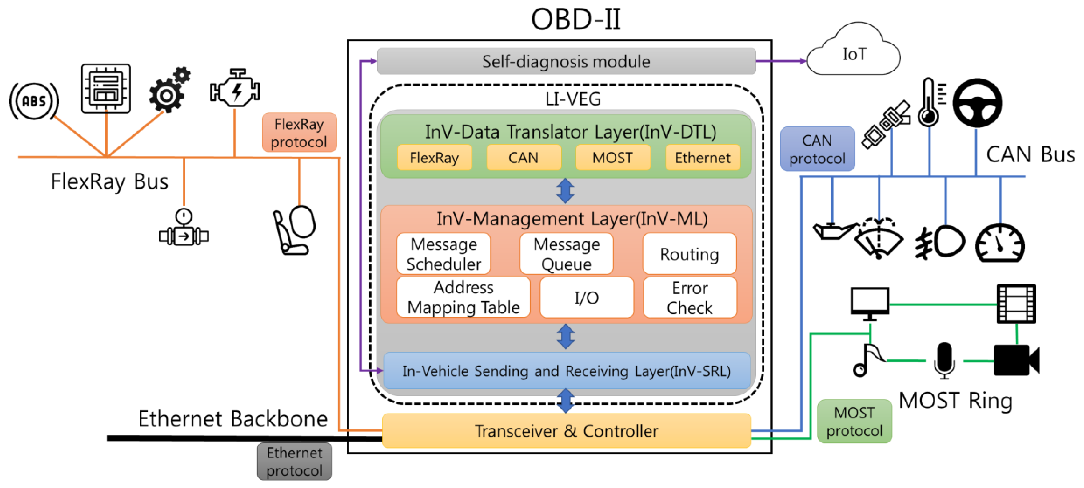
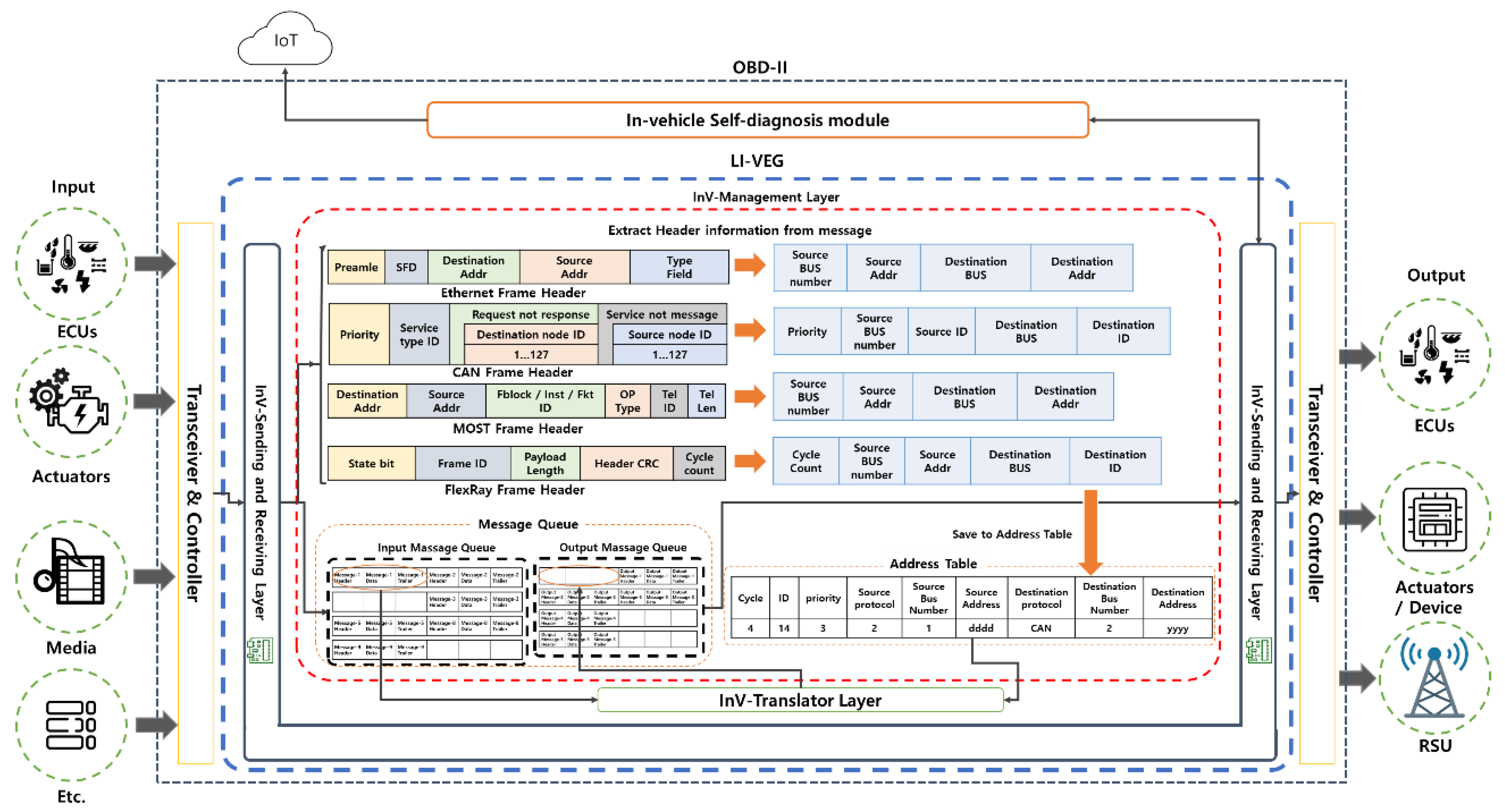
The LI-VEG enables mutual communication by translating the messages of the FlexRay, MOST, and CAN inside a vehicle into the message type of a destination protocol and translates the structure of an in-vehicle communication protocol into an Ethernet structure to support the mutual communication with the RSU outside a vehicle, and the connection with an Ethernet backbone. Because the paper on the self-diagnosis module has already been published [38], this paper only covers LI-VEG, not the self-diagnosis. Figure 2 shows the structure of OBD-II including the LI-VEG which is a part for the self-diagnosis of an autonomous vehicle.
The LI-VEG working in OBD consists of three layers: InV-SRL, InV-ML and InV-DTL. First, the InV-SRL receives the messages from FlexRay, CAN, MOST, and Ethernet and then transfers the received messages into the Gateway. Second, the InV-ML manages the message transmission and reception of FlexRay, CAN, MOST, and Ethernet and the Address Mapping Table. Third, the InV-DTL decomposes the messages of FlaxRay, CAN, MOST, and Ethernet and recomposes them to the frame suitable for a destination.
3.2. A Design of a Sending and Receiving Layer (InV-SRL)
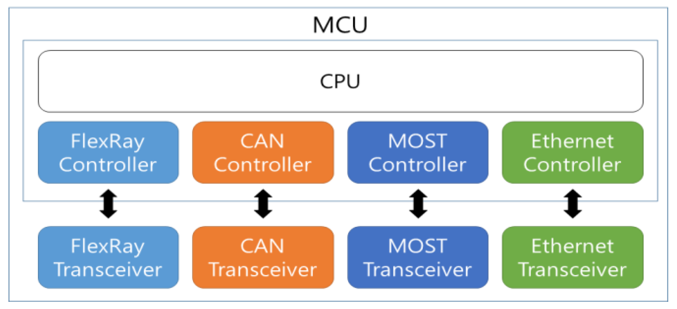
The InV-SRL acts as an interface to transmit and receive the messages between the InV-ML and hardware devices (transceiver and controller). A transceiver is a hardware device that transmits and receives the messages of each protocol. A controller used for message processing is embedded in the MCU. The controller stores the bus serial bits of messages in the MCU. Messages received through the transceiver and the controller are transmitted to the InV-ML via the InV-SRL.
If the InV-SRL receives a message, the received message is transferred to the InV-ML. The transferred message is stored in an Input Message Queue. If the InV-SRL needs to transmit the message to hardware devices, it receives the message stored in an Output Message Queue of the InV-ML and transmits it to hardware devices. Figure 3 shows the block diagram of the transceiver and the controller.
3.3. A Design of an InV-Management Layer (InV-ML)
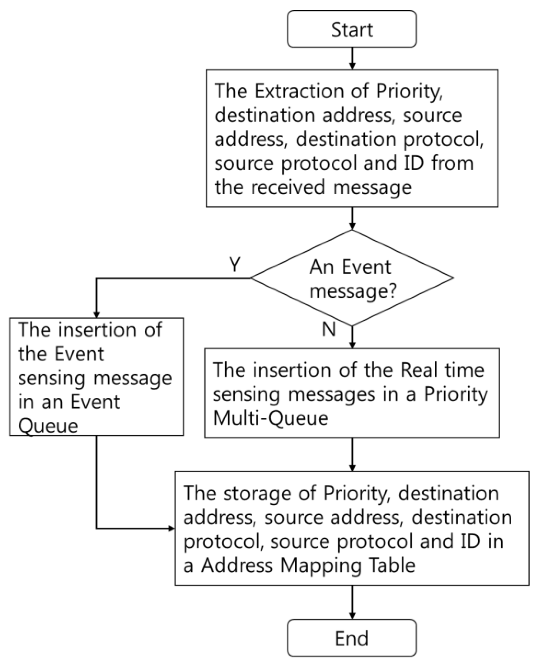
The InV-ML has two functions. First, the InV-ML receives messages from the InV-SRL and extracts only the necessary data, such as source, destination address, etc., from the received messages to makes the received messages lightweight. Only the extracted data are stored in an Address Mapping Table. It must rapidly be mapped to actual data in the Input Message Queue.
Second, if the extracted data are stored in the Address Mapping Table for mapping, the message is stored in the Input Message Queue according to the priority of a message. The Input Message Queue consists of a Priority Multi-Queue and an Event Queue. There are two types of data transferred from sensors: the real time sensing messages processed in the Priority Multi-Queue and the event sensing messages processed in the Event Queue. The event sensing messages is transmitted more rapidly than the real time sensing messages.
The Priority Multi-Queue is used to decide a priority between protocols and between inner messages of a protocol. The priority of protocol prevents the collision between protocols. The priority of messages provides emergent messages with higher priority and general messages with higher priority in proportion to the time when a message stays in the Input Message Queue.
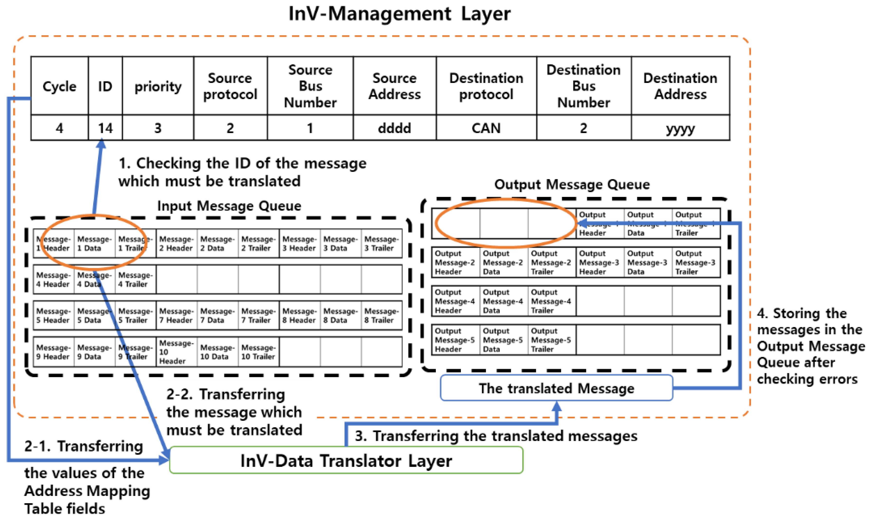
The Event Queue is used to process Event sensing messages and the messages of the Event Queue have higher priority than those of the Protocol Priority Multi-Queue. The Output messages of InV-ML are processed in the Output Message Queue. The Output Message Queue is similar to an Input Message Queue in terms of function. Figure 4 shows that the LI-VEG stores the received messages in an Input Massage Queue and only the necessary data from the message in an Address Mapping Table.
Figure 5 shows the process that a message which must be translated in the LI-VEG is made lightweight and is stored in the Input Message Queue. The operational process is as follows.
- The LI-VEG receives the messages from the ECUs, Actuators, and media of a vehicle and stores them in the Input Message Queue.
- The LI-VEG extracts only the data necessary for message translation such as source and destination address, and ID from a header for being lightweight. Because there is a cycle field describing a data transmission cycle in the case of FlexRay, the Cycle field must be extracted.
- Lightweight data are stored in an Address Mapping Table for the rapid message translation.
- The message in the Input Message Queue is translated in InV-TL and the extracted header information of the Address Mapping Table helps to translate it rapidly. The translated message is stored in the Output Message Queue.
- The message in the Output Message Queue is transmitted to a destination protocol bus.
The Field Name of Table 1 consists of Cycle, ID, Priority, Source Protocol, Source Bus Number, Source Address, Destination Protocol, Destination Bus Number, and Destination Address.
The header information of a FlexRay message is extracted and each value of the extracted header information is stored in the Ex1 column of Table 1.
The Cycle field value in the header information of a FlexRay message is stored in the Cycle field in the EX1 of Table 1 and the ID value in the header information of a FlexRay message is stored in the ID field in the EX1 of Table 1. The ID field value in the header information of a CAN message is stored in the ID field in the EX2 of Table 1. Because the header information of the CAN message has no a Cycle field, it remains blank.
Priority field value is stored in the Priority field in the EX1 of Table 1. Because the FlexRay uses a timer, not priority, the priority field value is not needed. In the case InV-ML receives a FlexRay message, 0 value is stored in the Priority field. The Priority value of the CAN message frame is stored in the Priority field in the EX2 of Table 1.
The Source Protocol field is 2 bits and has a source protocol number in it. If the Source Protocol field value is 00, it means a CAN protocol. If it is 01, it means a MOST protocol. If it is 10, it means a FlexRay protocol. If it is 11, it means an Ethernet protocol.
The source protocol bus number which sent a message is stored in the Source Bus Number field. Because the Source Protocol field value is 10 and Source Bus Number field value is 1 in the EX1 of Table 1, it means that a message was received from the Bus 1 using a FlexRay protocol. Because the Source Protocol field value is 00 and the Source Bus Number field value is 2 in the EX2 of Table 1, it means that a message was received from the Bus 2 using a CAN protocol.
The source address of the received message is stored in the Source Address field.
The Destination Protocol field is 2 bits large and has a destination protocol number in it. The destination protocol bus number is stored in the Destination Bus Number field.
The destination address of the received message is stored in a Destination Address field. If the header information is stored in the Address Mapping Table, the InV-ML transfers the stored header information and the original message of the Input Message Queue to the InV-DTL according to priority.
The stepwise process is shown in Figure 6.
- Before the Input Message Queue transfers messages to the InV-DTL, it searches for the tuple of the Address Mapping Table with the same the sending message ID as Address Mapping Table ID.
- The message which must be translated and the tuple of the Address Mapping Table are transferred to the InV-DTL.
- The InV-DTL translates messages, compares the destination and source address of the translated message to those of the Address Mapping Table. If they are all the same, the InV-DTL transfers the message to the InV-ML.
- The InV-ML sets the paths of the translated messages, and delivers the messages to the Output Message Queue and transfers the message of the Output Message Queue to the SRL according the paths.
3.4. A Design of the InV-DTL
The InV-DTL translates the messages received from the Input Massage Queue by using the Translation Table and transfers the translated messages to the Output Massage Queue of the InV-ML.
The InV-DTL works as follows.
- The InV-DTL receives the original message of the Input Massage Queue and the header information of the Address Mapping Table and generates the values of the Translation Table field by using the header information.
- The InV-DTL decomposes the header and trailer from the message.
- The InV-DTL translates the decomposed messages based on the Translation Table.
- The InV-DTL gives them sequential numbers from the Translation Table if the translated messages are divided.
- The translated messages are transferred to the Output Massage Queue of InV-ML.
- Every protocol is different in the attributes of the Translation Table fields. The Translation Tables such as “FlexRay to CAN” Table, “CAN to FlexRay” Table, “MOST to CAN” Table, and “Ethernet to MOST” Table are generated and the Translation Table field values are generated again whenever messages are translated.
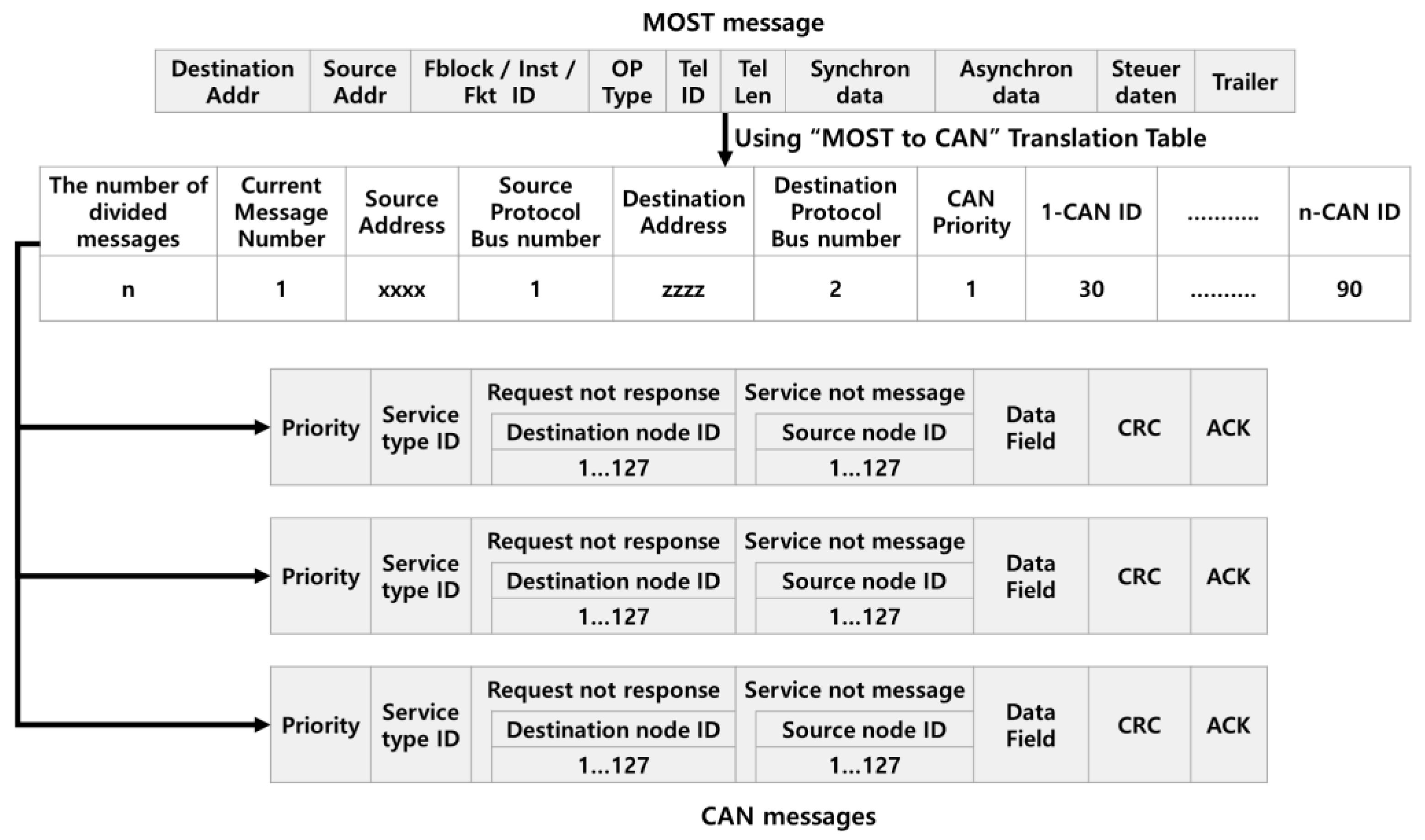
Figure 7 shows the “MOST to CAN” Translation Table translating MOST messages into CAN messages. The “MOST to CAN” Translation Table consists of the number of divided messages, Current Message Number, Source Address, Source Protocol Bus Number, Destination Address, Destination Protocol Bus Number, the CAN priority, and the CAN IDs. The CAN ID is used to enter the CAN Bus by Event. Tel ID and Tel Len field are translated into Service type ID of the CAN message by the CAN ID value of the Translation Table. The message numbers are given to every divided message sequentially. Destination Address of the MOST message is translated the Destination node ID of the CAN message by Destination Address and Destination Protocol Bus Number in the Translation Table. The Source Address of the MOST is translated to the Source node ID of the CAN message by Source Address and Source Protocol Bus Number in the Translation Table. The Request not response field value of the CAN message is always fixed as 1, and the Service not message field of the CAN message is always fixed as 0. The CAN Priority field value of the Translation Table is generated by using the Address Mapping Table. It is used to map the Priority field value of CAN message. The fields such as Fblock, Inst, Fkt ID and OP Type are functional blocks of the MOST message. They are not used in the CAN. The Synchronous data and the Asynchronous data are translated to the Data field value of the CAN message.
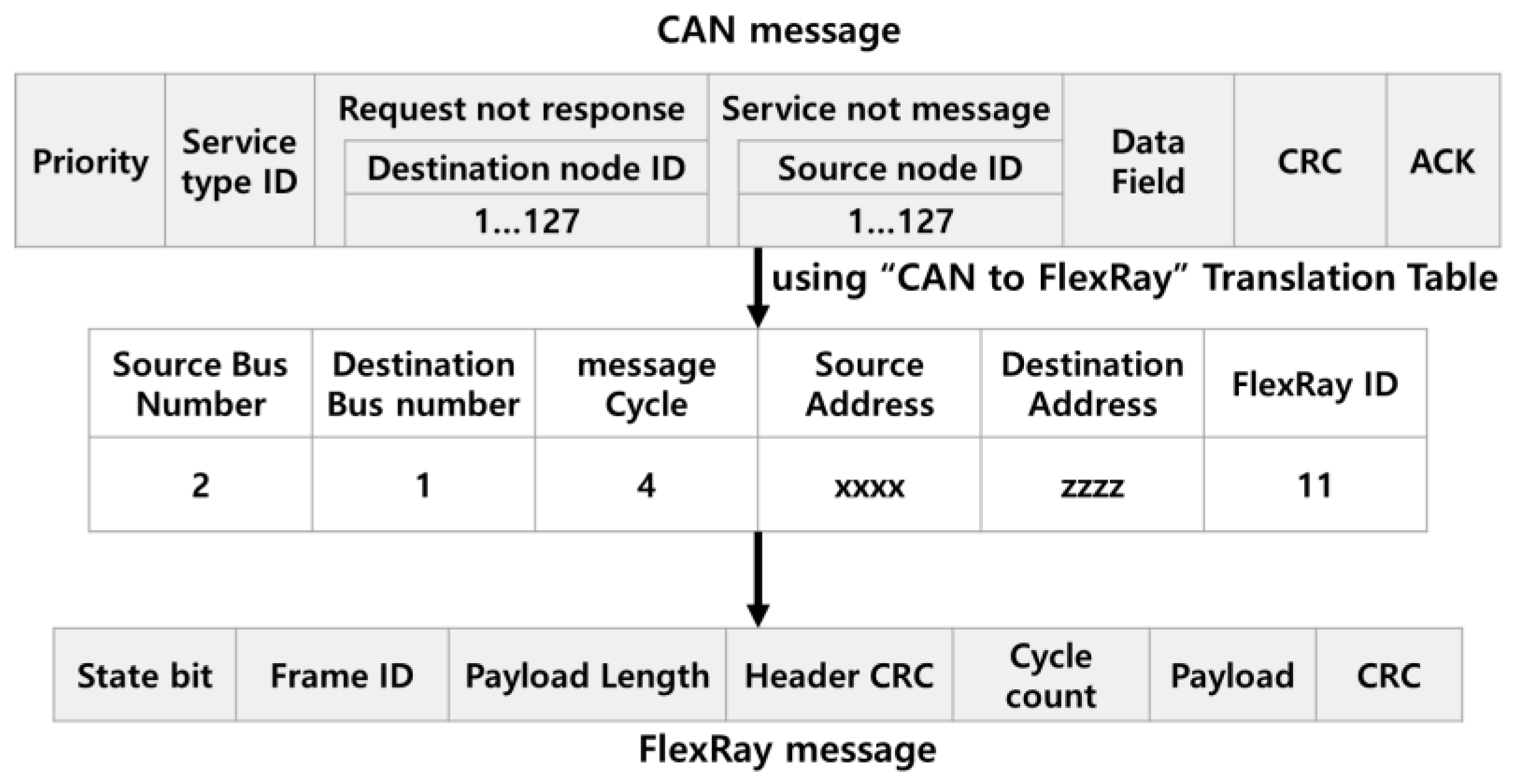
Figure 8 shows the “CAN to FlexRay” Translation Table translating CAN messages into FlexRay messages. Because the FlexRay is a protocol based on Timing, a Cycle field is used and a Priority and an ID field are not used when messages are translated. The translated messages enter a destination FlexRay Bus by using a Cycle value. Service type ID of the CAN message is translated into Frame ID of FlexRay message by FlexRay ID of the Translation Table. Message Cycle of the Translation Table is generated based on the Address Mapping Table, and is used to decide Cycle count of FlexRay message. Because the State bit, the Payload Length, the Header CRC and the CRC are not included in the CAN message, they are generated by InV-DTL.
Figure 9 shows the “MOST to Ethernet” Translation Table translating the MOST messages into the Ethernet messages. Because the Ethernet is used as a Backbone with high capacity, an attribute on Bus number is not generated in the Translation Table. Therefore, the Translation speed is the highest when the MOST messages are translated into the Ethernet messages. Destination Address value of the MOST message is translated Destination Address value of the Ethernet message by the Translation Table. Source Address of the MOST message is translated Source Address of the Ethernet message by the Translation Table. The Tel Len value is translated to the Length value of the Ethernet message by the Translation Table. The Synchronous data and the Asynchronous data are translated to the Data field value of the Ethernet message. The Preamble, the SFD and the Padding field values are generated by InV-DTL and FCS field must be made by CRC method.
If the message translation is completed, the translated message is stored in the Output Message Queue of the InV-ML. If the message arrived at the Output Message Queue normally, it is transferred to the destination protocol bus to which the message belongs according to priority or cycle. Because the FlexRay protocol uses a Bus based on Timing, it transfers the translated messages to a destination protocol bus by using Cycle field of a header. The transmission of messages is done in the InV-SRL.
This method enables the smooth communication of MOST, FlexRay and CAN, and, if MOST, FlexRay and CAN messages are translated in Ethernet messages, the Ethernet messages are translated in WAVE signals to be able to communicate with RSU using an in-vehicle WAVE-to-Ethernet module.
4. The Performance Analysis
The model shown in Figure 10 uses one gateway connected to two CAN buses, two FlexRay buses, two MOST buses and one Ethernet backbone to verify the LI-VEG performance proposed in this paper and each bus has four nodes.
The Main Processor of the LI-VEG uses ARM Cortex-A7 (900 Mhz) and is simulated in the RAM with these two experiments in PC.
In the first simulation environment, the transmission delay caused by message translation was measured while messages are transferred between four protocols (CAN, MOST, FlexRay and Ethernet). The transmission delay was measured based on the eight Message transmissions from CAN to FlexRay, the eight Message transmissions from CAN to Ethernet, and the eight Message transmissions from CAN to MOST. The transmission cycle of each message uses 14 ms. The transmission delay between the existing message mapping translation system not using a lightweight header and the message translation system using a lightweight header was compared. Table 2 shows the simulation environment of the first simulation.
In the second simulation environment, the transmission delay caused by overhead was measured. The overhead happens in each protocol bus because of the continuous signal from the CAN. Transmission delay between the existing message translation system and the proposed message translation system was compared according as network traffic increases. In the same way as the first experiment, transmission delay was measured in the case the CAN messages are translated to the other three protocols.
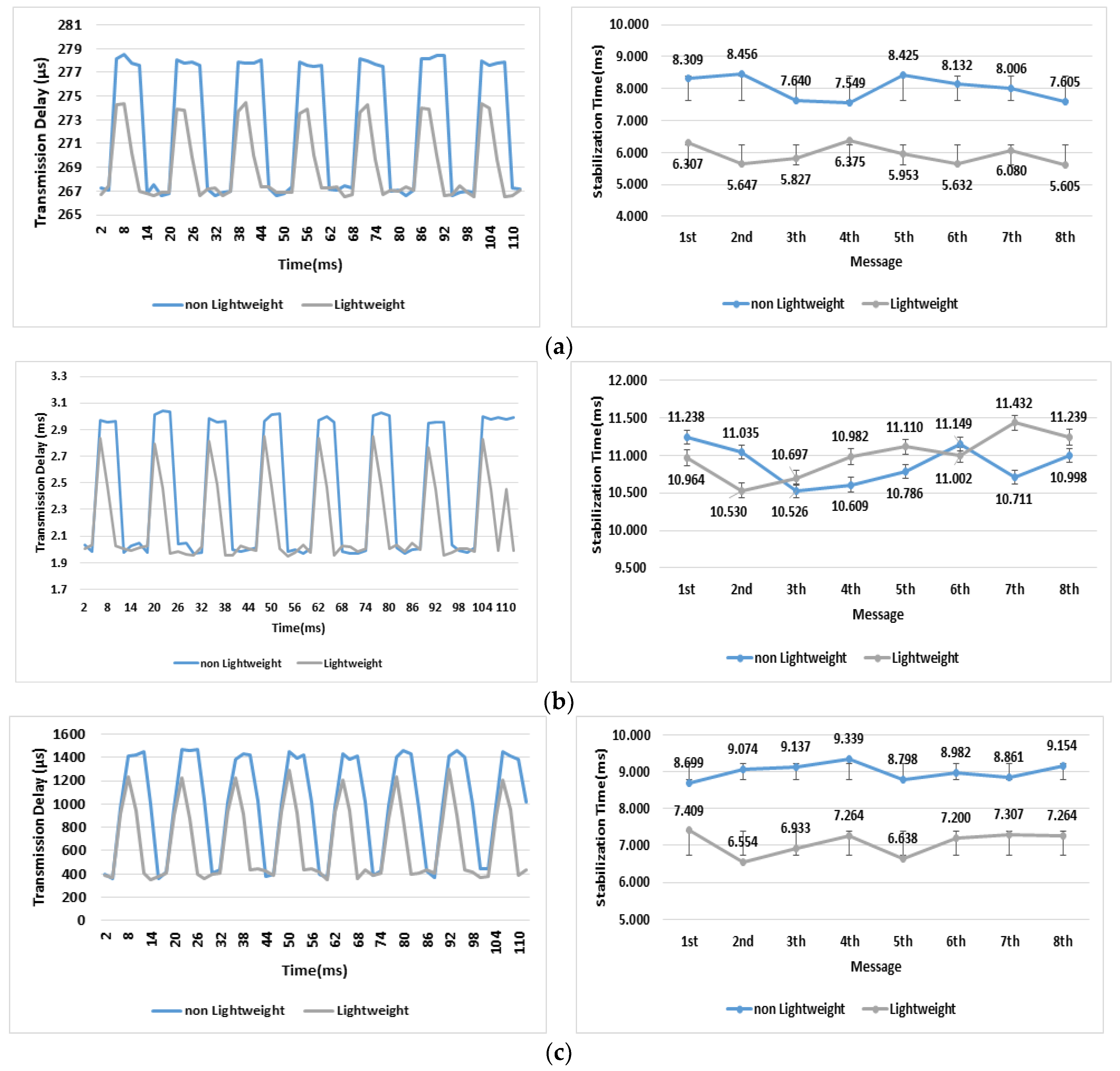
Figure 11a–c shows maximum transmission delay and its stabilization time when the CAN messages are transferred to the other protocols. The transmission delay means the time that it takes for a source message to be translated into a destination message in the LI-VEG. The stabilization time means the time between when translation overhead occurs and when its overhead disappears. Figure 11a shows the transmission delay and stabilization time when messages are transferred from the CAN bus to the FlexRay bus. In the transmission, it takes maximum 278 μs transmission delay for the existing method to store and translate a message and about 8 ms to stabilize the transmission delay. It takes a maximum of 274 μs for the proposed method to store and transform a message and about 6 ms to stabilize the transmission delay. Therefore, the maximum transmission delay is improved by about 2% and its stabilization time about 25%.
Figure 11b shows the transmission delay and stabilization time when messages are transferred from CAN bus to MOST bus. In the transmission, it takes maximum 3.03 ms transmission delay for the existing method to store and transform a message and 11 ms to stabilize the transmission delay. It takes a maximum of 2.84 ms for the proposed method to store and transform a message and 11 ms to stabilize the transmission delay. Therefore, the maximum transmission delay is improved by about 7% and its stabilization time is the same.
Figure 11c shows the transmission delay and stabilization time when messages are transferred from CAN bus to Ethernet bus. In the transmission, it takes maximum 1.47 ms transmission delay for the existing method to store and translate a message and 9 ms to stabilize the transmission delay. It takes a maximum of 1.29 ms for the proposed method to store and transform a message and 7 ms to stabilize the transmission delay. Therefore, the maximum transmission delay is improved by about 11% and its stabilization time about 20%.
Table 3 shows how much the proposed method is improved in comparison to the existing method. Overall, the transmission delay time about message translation and transmission is reduced by an average of 10.83%. That is, if the lightweight method is used, transmission delay is reduced and data processing is improved.
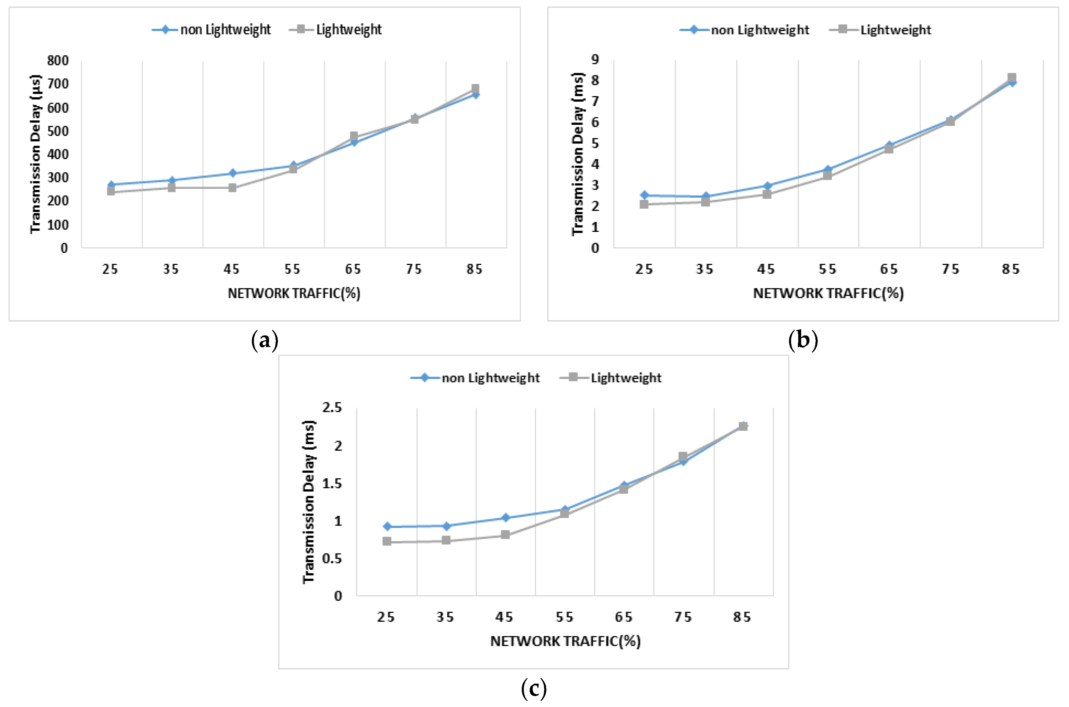
Figure 12 shows the average transmission delay by overhead happening when continuous messages are transferred from a CAN bus to a destination protocol.
When messages are transferred from the CAN to the FlexRay, Figure 12a shows an average transmission delay according to network traffic increase. In the case the network traffic is 25%, the transmission delay of the existing method was measured as about 275 μs and that of the proposed method was measured as about 250 μs. In the case the network traffic is 85%, the transmission delay of the existing method was measured as about 656 μs and that of the proposed method was measured as about 670 μs. Therefore, when traffic increase is low, the proposed method is faster by about 9% than the existing method. However, when traffic increase is high, there is no difference between the methods.
When messages are transferred from the CAN to the MOST, Figure 12b shows an average transmission delay according to network traffic increase. In thecase the network traffic is 25%, the transmission delay of the existing method was measured as about 2 ms and that of the proposed method was measured as about 2.5 ms. In the case the network traffic is 85%, the transmission delay of the existing method was measured as about 7.9 ms and that of the proposed method was measured as about 8.1 ms. Therefore, when traffic increase is low, the proposed method is faster by about 20% than the existing method. However, when traffic increase is high, there is no difference between the methods.
When messages are transferred from the CAN to the Ethernet, Figure 12c shows an average transmission delay according to network traffic increase. In the case the network traffic is 25%, the transmission delay of the existing method was measured as about 0.9 ms and that of the proposed method was measured as about 0.7 ms. In the case the network traffic is 85%, the transmission delay of the existing method was measured as about 2.26 ms and that of the proposed method was measured as about 2.24 ms. Therefore, when traffic increase is low, the proposed method is faster by about 20% than the existing method. However, when traffic increase is high, there is almost no difference between the methods.
In brief, the transmission delay of the proposed method is lower as traffic value gets smaller. There is almost no difference between the two methods as traffic value gets larger, which it means that the two methods have the same transmission delay characteristic.
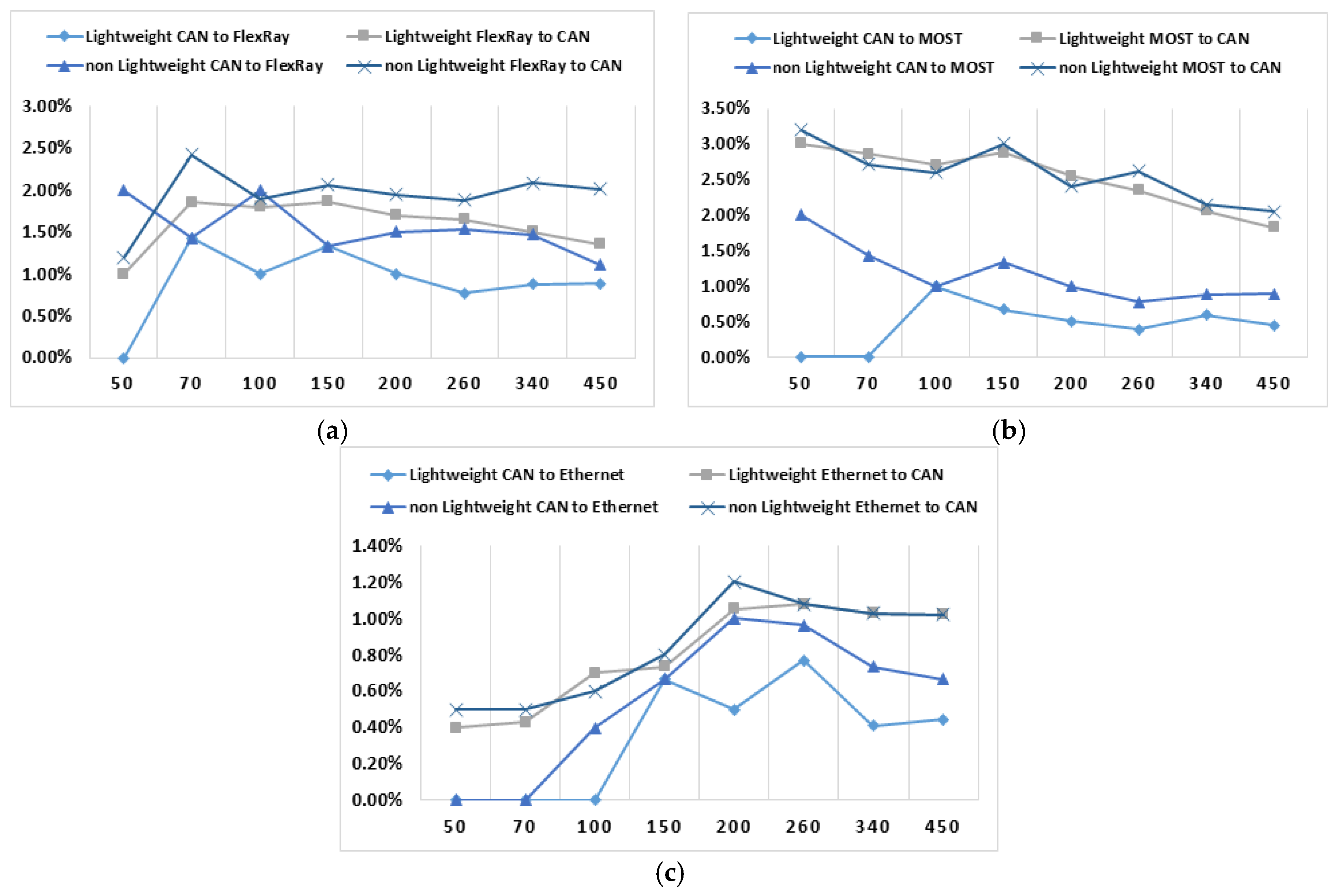
When messages are sent and received between a CAN bus and a FlexRay bus, Figure 13a shows the error rate according to the number of messages. The error rate was measured as follows.
First, the error rate was measured when the CAN messages are transferred to a FlexRay bus. In the case 50 messages were transferred, the proposed method showed an error rate of 0% and the existing method of 2%. In the case 100 messages were transferred, the proposed method showed an error rate of 1% and the existing method of 2%. In the case 340 messages were transferred, the proposed method showed an error rate of 0.88% and the existing method of 1.47%. Therefore, the error rate of the proposed method is lower by about 1.3% compared to that of the existing method as the number of messages gets larger. The average error rate of the proposed method is 0.91% and that of the existing method is 1.55%.
Second, the error rate was measured when the FlexRay messages are translated into a CAN bus. In the case 50 messages were transferred, the proposed method showed an error rate of 1% and the existing method of 1.2%. In the case 100 messages were transferred, the proposed method showed an error rate of 1.8% and the existing method of 1.9%. In the case 340 messages were transferred, the proposed method showed an error rate of 1.5% and the existing method of 2.09%. Therefore, the error rate of the proposed method is lower by about 0.5% compared to that of the existing method as the number of messages gets larger. The average error rate of the proposed method is 1.59% and that of the existing method is 1.94%. Here, because one FlexRay message was divided into several CAN messages, the average error rate of the second gets higher by about 0.5% compared to that of the first.
When messages are sent and received between a CAN bus and a MOST bus, Figure 13b shows the error rate according to the number of messages. The error rate was measured as follows.
First, the error rate was measured when the CAN messages are transferred to a MOST bus. In the case 50 messages were transferred, the proposed method showed an error rate of 0% and the existing method 2%. In the case 100 messages were transferred, the proposed method showed an error rate of 1% and the existing method of 1%. In the case 340 messages were transferred, the proposed method showed an error rate of 0.59% and the existing method of 0.88%. Therefore, the error rate of the proposed method is lower by about 0.3% compared to that of the existing method as the number of messages gets larger. The average error rate of the proposed method is 0.45% and that of the existing method is 1.16%.
Second, the error rate was measured when the MOST messages are transferred to a CAN bus. In the case 50 messages were transferred, the proposed method showed an error rate of 3% and the existing method of 3.2%. In the case 100 messages were transferred, the proposed method showed an error rate of 2.7% and the existing method of 2.6%. In the case 340 messages were transferred, the proposed method showed an error rate of 2.06% and the existing method of 2.15%. Therefore, the error rate of the proposed method is lower by about 0.1% compared to that of the existing method as the number of messages gets larger. The average error rate of the proposed method is 2.53% and that of the existing method is 2.59%. Here, because one MOST message is divided into several CAN messages, the average error rate of the second gets higher by about 2% compared to that of the first.
When messages are sent and received between a CAN bus and an Ethernet bus, Figure 13c shows the error rate according to the number of messages. The error rate was measured as follows.
First, the error rate was measured when the CAN messages are transferred to an Ethernet backbone. In the case 50 messages were transferred, the proposed method showed an error rate of 0% and the existing method of 0%. In the case 100 messages were transferred, the proposed method showed an error rate of 0% and the existing method of 0.4%. In the case 340 messages were transferred, the proposed method showed an error rate of 0.41% and the existing method of 0.74%. Therefore, the error rate of the proposed method is lower by about 0.5% compared to that of the existing method as the number of messages gets larger. The average error rate of the proposed method is 0.35% and that of the existing method is 0.55%.
Second, the error rate is measured when the Ethernet messages are transferred to a CAN bus. In the case 50 messages were transferred, the proposed method showed an error rate of 0.4% and the existing method of 0.5%. In the case 100 messages were transferred, the proposed method showed an error rate of 0.7% and the existing method of 0.6%. In the case 340 messages were transferred, the proposed method showed an error rate of 1.03% and the existing method of 1.03%. Therefore, the average error rate of the proposed method is 0.81% and that of the existing method is 0.84%. The proposed method is lower than the existing method by about 0.03%. Here, the average error rate of the second gets higher by about 0.5% compared to that of the first. Overall, this experiment says that the error rate of the proposed method is lower compared to that of the existing method.
According to the three experiments above, the LI-VEG proposed in this paper has the following advantages:
- When messages are transferred to the other protocol, the LI-VEG has lower transmission delay than the existing protocols.
- When network traffic becomes lower, the LI-VEG has a lower transmission delay than the existing protocols. However, when network traffic becomes higher, the LI-VEG has almost the same transmission delay as the existing protocols.
- When messages are transferred between protocols, the LI_VEG has a lower error rate than the existing protocols.
5. Conclusions
This paper proposes the LI-VEG for smooth communication between in-vehicle protocols and presents results from three experiments. The results are as follows. The LI-VEG reduces the transmission delay time by an average of 10.83% and the error rate by 0.8% for message translation and transmission, compared to the existing in-vehicle gateways. When network traffic becomes lower, the LI-VEG reduces the transmission delay by about 16.3%. Therefore, the LI-VEG has a lower error rate and a lower transmission delay than the existing method when a message is translated and transferred.
According to the experiment, the LI-VEG has the following characteristics. First, the header is much lighter because only the necessary information for transformation is extracted from the header information of a message. Second, because the Input Queue and Output Queue managing messages are classified into a Priority Multi-Queue and an Event Queue, the LI-VEG translates emergent messages more rapidly than the existing FIFO. Third, the LI-VEG supports communication among all primary protocols used inside a current vehicle.
The LI-VEG must be tested on real vehicles. If the real experiment on the vehicle is almost the same as the simulation result, the LI-VEG could be applied to the gateway of future autonomous vehicles.
Author Contributions
B.L. proposed the idea. Y.J., S.S. and E.J. made the paper based on the idea and carried out the experiments in Korean Language. B.L. guided and supervised the research and translated the paper into English. All authors read and approved the final manuscript.
Funding
This work was supported by the National Research Foundation of Korea (NRF) grant funded by the Korea government (MSIT) (No. NRF-2018R1A2B6007710).
Conflicts of Interest
The authors declare no conflict of interest.
References
- Gateway Solutions Iot Brief. Available online: https://www.intel.com/content/dam/www/public/us/en/documents/product-briefs/gateway-solutions-iot-brief.pdf (accessed on 17 May 2018).
- Leen, G.; Hefferman, D.; Dunne, A. Digital Networks in the automotive vehicle. IEEE Comput. Control Eng. J. 1999, 10, 257–266. [Google Scholar] [CrossRef]
- Jeong, Y.; Sonm, S.; Jeong, E.; Lee, B. An Integrated Self-Diagnosis System for an Autonomous Vehicle Based on an IoT Gateway and Deep Learning. Appl. Sci. 2018, 8, 1164. [Google Scholar] [CrossRef]
- Lin, C.E.; Shiao, Y.-S.; Li, C.C.; Yang, S.H.; Lin, S.H.; Lin, C.Y. Real-Time Remote Onboard Diagnostics Using Embedded GPRS Surveillance Technology. IEEE Trans Veh. Technol. 2007, 56, 1108–1118. [Google Scholar] [CrossRef]
- Zou, X.D.; Wang, F.Y.; Qiu, R. The Development of the on Board Diagnostics System on the Keyword Protocol. Appl. Mech. Mater. 2010, 43, 752–755. [Google Scholar]
- Ochs, T.; Schittenhelm, H.; Genssle, A.; Kamp, B. Particulate Matter Sensor for On Board Diagnostics (OBD) of Diesel Particulate Filters (DPF). SAE Int. J. Fuels Lubr. 2010, 3, 61–69. [Google Scholar] [CrossRef]
- Kamimoto, T. A review of soot sensors considered for on-board diagnostics application. Int. J. Eng. Res. 2017, 18, 5–6. [Google Scholar] [CrossRef]
- Necker, T.; Garnatz, O. On-board Diagnostics Meets AUTOSAR. ATZextra Worldw. 2013, 18, 37. [Google Scholar] [CrossRef]
- Chen, C.L.; Hsu, C.W. Enhancement of Ev On-Board Diagnostics System into Preliminary Operation Using Estimation Theory. Appl. Mech. Mater. 2013, 391, 592–595. [Google Scholar] [CrossRef]
- Sujit, H.; Ramachandra, K.; Reddy, N.; Vivek, R.V.; Karanth, S.; Kamath, T. A novel dynamic traffic management system using on board diagnostics and Zigbee protocol. In Proceedings of the 2016 International Conference on Communication and Electronics Systems (ICCES), Coimbatore, India, 21–22 October 2016. [Google Scholar]
- Kulkarni, P.; Rajani, P.K.; Varma, K. Development of On Board Diagnostics (OBD) testing tool to scan emission control system. In Proceedings of the 2016 International Conference on Computing Communication Control and automation (ICCUBEA), Pune, India, 12–13 August 2016. [Google Scholar]
- Khorsravinia, K.; Hassan, M.K.; Abdul Rahman, R.Z.; Rahman Al-Haddad, S.A. Integrated OBD-II and mobile application for electric vehicle (EV) monitoring system. In Proceedings of the 2017 IEEE 2nd International Conference on Automatic Control and Intelligent Systems (I2CACIS), Kota Kinabalu, Malaysia, 21 October 2017. [Google Scholar]
- Malekian, R.; Moloisane, N.R.; Nair, L.; Maharaj, B.T.; Chude-Okonkwo, U.A.K. Design and Implementation of a Wireless OBD II Fleet Management System. IEEE Sens. J. 2016, 17, 1154–1164. [Google Scholar] [CrossRef]
- Alvear, O.; Calafate, C.Y.; Cano, J.C.; Manzoni, P. Validation of a vehicle emulation platform supporting OBD-II communications. In Proceedings of the 2015 12th Annual IEEE Consumer Communications and Networking Conference (CCNC), Las Vegas, NV, USA, 9–12 January 2015. [Google Scholar]
- Tsai, Y.C.; Lee, W.H.; Chou, C.M. A safety driving assistance system by integrating in-vehicle dynamics and real-time traffic information. In Proceedings of the 2017 IEEE 8th International Conference on Awareness Science and Technology (iCAST), Taichung, Taiwan, 8–10 November 2017. [Google Scholar]
- Choi, E.; Chang, S. A consumer tracking estimator for vehicles in GPS-free environments. IEEE Trans. Consum. Electron. 2017, 63, 450–458. [Google Scholar] [CrossRef]
- Chou, Y.S.; Mo, Y.C.; Su, J.P.; Chang, W.J.; Chen, L.B.; Tang, J.J.; Yu, C.Y. i-Car system: A LoRa-based low power wide area networks vehicle diagnostic system for driving safety. In Proceedings of the 2017 International Conference on Applied System Innovation (ICASI), Sapporo, Japan, 13–17 May 2017. [Google Scholar]
- Wey, C.L.; Hsu, C.H.; Chang, K.C.; Jui, P.C. Enhancement of Controller Area Network (CAN) bus arbitration mechanism. In Proceedings of the 2013 International Conference on Connected Vehicles and Expo (ICCVE), Las Vegas, NV, USA, 2–6 December 2013. [Google Scholar]
- Chen, J.; Cao, D.; Lv, X. Design of FlexRay-based communication on triplex redundancy flight control computer. In Proceedings of the 2015 Chinese Automation Congress (CAC), Wuhan, China, 27–29 November 2015. [Google Scholar]
- Yang, J.S.; Lee, S.; Lee, K.C.; Kim, M.H. Design of FlexRay-CAN gateway using node mapping method for in-vehicle networking systems. In Proceedings of the 2011 11th International Conference on Control, Automation and Systems, Gyeonggi-do, South Korea, 26–29 October 2011. [Google Scholar]
- Mejdi, H.; Jedli, B.; Hasnaoui, S. Designing a FlexRay controller—From SDL to StateFlow and Simulink blocks: Generation and verification. In Proceedings of the 2017 8th International Conference on Information and Communication Systems (ICICS), Irbid, Jordan, 4–6 April 2017. [Google Scholar]
- Wang, Y.; Liu, H.; Huang, B.; Sun, X. Frame Design for Vehicular FlexRay Network Based on Transmission Reliability and Slot Utilization. In Proceedings of the 2016 9th International Symposium on Computational Intelligence and Design (ISCID), Hangzhou, China, 10–11 December 2016; pp. 447–452. [Google Scholar]
- Chen, Y.Y.; Leu, K.L. An Effective Two-Level Redundancy Approach for FlexRay Network Systems. In Proceedings of the 2016 46th Annual IEEE/IFIP International Conference on Dependable Systems and Networks Workshop (DSN-W), Toulouse, France, 28 June–1 July 2016; pp. 54–55. [Google Scholar]
- Gu, Z.; Han, G.; Zeng, H.; Zhao, Q. Security-Aware Mapping and Scheduling with Hardware Co-Processors for FlexRay-Based Distributed Embedded Systems. IEEE Trans. Parallel Distrib. Syst. 2016, 27, 3044–3057. [Google Scholar] [CrossRef]
- Jang, S.J.; Jeon, J.W. Software reprogramming performance analysis of CAN FD and FlexRay protocols. In Proceedings of the 2015 IEEE International Conference on Information and Automation, Lijiang, China, 8–10 August 2015. [Google Scholar]
- Abdellaoui, Z.; Bouhouch, R.; Jaouaini, H.; Hasnaoui, S. FlexRay networks for SAE benchamrk application using DDS middleware: Development of FlexRay driver and its Simulink Blockset implementation. In Proceedings of the 2015 2nd World Symposium on Web Applications and Networking (WSWAN), Sousse, Tunisia, 21–23 March 2015. [Google Scholar]
- Abdellaoui, Z.; Mbarek, I.B.; Bouhouch, R.; Hasnaoui, S. DDS middleware on FlexRay network: Simulink blockset implementation of wheel's sub-blocks and its adaptation to DDS concept. In Proceedings of the 2015 IEEE 9th International Symposium on Intelligent Signal Processing (WISP) Proceedings, Siena, Italy, 15–17 May 2015. [Google Scholar]
- Zeng, W.; Khalid, M.; Chowdhury, S. A qualitative comparison of FlexRay and Ethernet in vehicle networks. In Proceedings of the 2015 IEEE 28th Canadian Conference on Electrical and Computer Engineering (CCECE), Halifax, NS, Canada, 3–6 May 2015; pp. 571–576. [Google Scholar]
- Amel, B.N.; Rim, B.; Houda, J.; Salem, H.; Khaled, J. Flexray versus Ethernet for vehicular networks. In Proceedings of the 2014 IEEE International Electric Vehicle Conference (IEVC), Florence, Italy, 17–19 December 2014. [Google Scholar]
- Mundhenk, P.; Sagstetter, F.; Steinhorst, S.; Lukasiewycz, M.; Chakraborty, S. Policy-based message scheduling using FlexRay. In Proceedings of the 2014 International Conference on Hardware/Software Codesign and System Synthesis (CODES+ISSS), New Delhi, India, 12–17 October 2014. [Google Scholar]
- Yan, W.; Lifang, W.; Chenglin, L.; Fang, L. In-vehicle FlexRay bus monitoring system. In Proceedings of the 2014 IEEE Conference and Expo Transportation Electrification Asia-Pacific (ITEC Asia-Pacific), Beijing, China, 31 August–3 September 2014. [Google Scholar]
- Dong, Z.H.; Piao, Z.Y.; Jang, I.G.; Chung, J.G.; Lee, C.D. Design of FlexRay-MOST gateway using static segments and control messages. In Proceedings of the 2012 IEEE International Symposium on Circuits and Systems, Seoul, South Korea, 20–23 May 2012. [Google Scholar]
- Lee, S.; Cho, B.S.; Choi, Y.J.; Baek, K.R. Implementation of MOST/CAN network protocol. In Proceedings of the 2011 International Conference on Electrical and Control Engineering, Yichang, China, 16–18 September 2011. [Google Scholar]
- Seo, H.S.; Kim, B.C.; Park, P.S.; Lee, C.D.; Lee, S.S. Design and implementation of a UPnP-can gateway for automotive environments. Int. J. Autom. Technol. 2013, 14, 91–99. [Google Scholar] [CrossRef]
- Luo, F.; Yang, T.Y.; Liu, C. Development of Automatic CAN Gateway Test System. Appl. Mech. Mater. 2014, 734, 161–167. [Google Scholar]
- Mangan, S.; Wang, J. Development of a Novel Sensorless Longitudinal Road Gradient Estimation Method Based on Vehicle CAN Bus Data. Inst. Electr. Electron. Eng. 2007, 12, 375–386. [Google Scholar] [CrossRef]
- Gugapriya, G.; Siyal, K. Anti-Theft Vehicle Locking System using CAN. Indian J. Sci. Technol. 2016, 9, 45. [Google Scholar]
- Guo, H.; Ngoh, L.H.; Wu, Y.D.; Teo, J.C.M. Secure wireless vehicle monitoring and control. In Proceedings of the 2009 IEEE Asia-Pacific Services Computing Conference (APSCC), Singapore, 7–11 December 2009. [Google Scholar]
Figure 1.
Vehicle gateways that need to handle in-vehicle sensor data.

Figure 2.
The structure of the LI-VEG.

Figure 3.
The block diagram of the hardware devices.

Figure 4.
The flowchart to process the received message.

Figure 5.
The movement of messages in InV-ML.

Figure 6.
Message Delivery Scenario.

Figure 7.
The Translation of MOST into CAN message by the Translation Table.

Figure 8.
The Translation of a CAN into a FlexRay message by Translation Table.

Figure 9.
The Transformation of MOST into Ethernet message by Mapping.

Figure 10.
The simulation Model.

Figure 11.
The transmission delay and the Stabilization Time when The CAN messages are translated. (a) From CAN to FlexRay, (b) From CAN to MOST, (c) From CAN to Ethernet.
Figure 11.
The transmission delay and the Stabilization Time when The CAN messages are translated. (a) From CAN to FlexRay, (b) From CAN to MOST, (c) From CAN to Ethernet.

Figure 12.
The transmission delay as traffic is increased. (a) CAN to FlexRay, (b) CAN to MOST, (c) CAN to Ethernet.
Figure 12.
The transmission delay as traffic is increased. (a) CAN to FlexRay, (b) CAN to MOST, (c) CAN to Ethernet.

Figure 13.
The error rate according to message quantity. (a) The error rate between the CAN and the FlexRay, (b) The error rate between the CAN and the MOST, (c) The error rate between the CAN and the Ethernet.
Figure 13.
The error rate according to message quantity. (a) The error rate between the CAN and the FlexRay, (b) The error rate between the CAN and the MOST, (c) The error rate between the CAN and the Ethernet.


Table 1.
The example of an Address Mapping Table.
| Field Name | Ex1 (FlexRay) | Ex2 (CAN) | Ex3 (MOST) | Ex4 (Ethernet) |
|---|---|---|---|---|
| Cycle | 4 | 0 | 1 | 2 |
| ID | 12 | 15 | 57 | 22 |
| Priority | 0 | 3 | 2 | 4 |
| Source Protocol | 10 | 00 | 01 | 11 |
| Source Bus Number | 1 | 2 | 2 | 0 |
| Source Address | 1002 | 0452 | 8847 | 4571 |
| Destination Protocol | 00 | 01 | 10 | 00 |
| Destination Bus Number | 2 | 2 | 1 | 1 |
| Destination Address | 0512 | 9960 | 1140 | 0324 |
Table 2.
The Simulation Environment.
| Source Protocol | CAN | CAN | CAN |
|---|---|---|---|
| destination protocol | FlexRay | MOST | Ethernet |
| the number of message transmissions | 8 | 8 | 8 |
| transmission cycle | 14 ms | 14 ms | 14 ms |
Table 3.
The improvement rate of the proposed method.
| Direction | The Improvement Rate of Transmission Delay | The Improvement Rate of Stabilization Time |
|---|---|---|
| From CAN to FlexRay | 2% | 25% |
| From CAN to MOST | 7% | 0% |
| From CAN to Etherney | 11% | 20% |
© 2018 by the authors. Licensee MDPI, Basel, Switzerland. This article is an open access article distributed under the terms and conditions of the Creative Commons Attribution (CC BY) license (http://creativecommons.org/licenses/by/4.0/).
Share and Cite
MDPI and ACS Style
Jeong, Y.; Son, S.; Jeong, E.; Lee, B. A Design of a Lightweight In-Vehicle Edge Gateway for the Self-Diagnosis of an Autonomous Vehicle. Appl. Sci. 2018, 8, 1594. https://doi.org/10.3390/app8091594
AMA Style
Jeong Y, Son S, Jeong E, Lee B. A Design of a Lightweight In-Vehicle Edge Gateway for the Self-Diagnosis of an Autonomous Vehicle. Applied Sciences. 2018; 8(9):1594. https://doi.org/10.3390/app8091594
Chicago/Turabian StyleJeong, YiNa, SuRak Son, EunHee Jeong, and ByungKwan Lee. 2018. "A Design of a Lightweight In-Vehicle Edge Gateway for the Self-Diagnosis of an Autonomous Vehicle" Applied Sciences 8, no. 9: 1594. https://doi.org/10.3390/app8091594
Note that from the first issue of 2016, this journal uses article numbers instead of page numbers. See further details here.