Article

Modeling of the Mechanical Behavior of 3D Bioplotted Scaffolds Considering the Penetration in Interlocked Strands

by
Saman Naghieh
1,*,
M. D. Sarker
1,
Mohammad Reza Karamooz-Ravari
2,
Adam D. McInnes
1 and
Xiongbiao Chen
1,3,*
1
Division of Biomedical Engineering, College of Engineering, University of Saskatchewan, Saskatoon, SK S7N 5B1, Canada
2
Department of Mechanical Engineering, Graduate University of Advanced Technology, Kerman 76318-18356, Iran
3
Department of Mechanical Engineering, College of Engineering, University of Saskatchewan, Saskatoon, SK S7N 5B1, Canada
*
Authors to whom correspondence should be addressed.
Appl. Sci. 2018, 8(9), 1422; https://doi.org/10.3390/app8091422
Submission received: 22 June 2018 / Revised: 27 July 2018 / Accepted: 15 August 2018 / Published: 21 August 2018

Abstract

:
Three-dimensional (3D) bioplotting has been widely used to print hydrogel scaffolds for tissue engineering applications. One issue involved in 3D bioplotting is to achieve the scaffold structure with the desired mechanical properties. To overcome this issue, various numerical methods have been developed to predict the mechanical properties of scaffolds, but limited by the imperfect representation of one key feature of scaffolds fabricated by 3D bioplotting, i.e., the penetration or fusion of strands in one layer into the previous layer. This paper presents our study on the development of a novel numerical model to predict the elastic modulus (one important index of mechanical properties) of 3D bioplotted scaffolds considering the aforementioned strand penetration. For this, the finite element method was used for the model development, while medium-viscosity alginate was selected for scaffold fabrication by the 3D bioplotting technique. The elastic modulus of the bioplotted scaffolds was characterized using mechanical testing and results were compared with those predicted from the developed model, demonstrating a strong congruity between them. Once validated, the developed model was also used to investigate the effect of other geometrical features on the mechanical behavior of bioplotted scaffolds. Our results show that the penetration, pore size, and number of printed layers have significant effects on the elastic modulus of bioplotted scaffolds; and also suggest that the developed model can be used as a powerful tool to modulate the mechanical behavior of bioplotted scaffolds.

Graphical Abstract

1. Introduction

One aim of tissue engineering is to develop tissue/organ substitutes or scaffolds, based on the principles of biology and engineering, for the repair or replacement of damaged tissues and organs [1,2]. For this, scaffolds, typically of a three-dimensional (3D) porous structure made from biomaterials, play an important role in supporting and/or promoting cell growth, tissue regeneration, and transport of nutrients and wastes. Design and fabrication of scaffolds have proven to be a challenging task [3]. One important issue in the design and fabrication of scaffolds is achieving the desired mechanical properties to match those of tissue at the site of implantation. More specifically, the scaffold must be strong enough to resist structural collapse upon implantation, yet sufficiently compliant so as not to damage the surrounding tissues.
Tissue scaffolds can be fabricated by either conventional or modern techniques. Conventional methods, like electrospinning, are limited for the fabrication of 3D scaffolds with interconnected pores [4,5] and in some cases, organic solvents have to be used, thus being detrimental for cellular proliferation/differentiation [6]. Nowadays, additive manufacturing (AM) techniques have drawn considerable attention since they allow fabrication of scaffolds layer-by-layer [7], and thus open a new door to create scaffolds with a complex 3D microstructure and a controllable pore shape and size [8]. Among various AM techniques, extrusion-based 3D bioplotting shows promise, where bioinks are extruded from either one or multiple needles and thus form 3D scaffolds [9,10,11,12], as shown in Figure 1 (a pneumatic-based 3D bioplotter extruding biomaterials from one needle). Notably, the bioink for bioplotting can be prepared from the biomaterials favorable for cells, thus being capable of incorporating cells and proteins in the scaffold fabrication process [13,14]. For this, hydrogels have been widely utilized as they are able to provide an appropriate environment for encapsulating cells and growth factors [15]. This is mainly due to the fact the hydrogels involve a large amount of water in their polymeric 3D network, which is favorable to cell growth and tissue regeneration [16,17]. Alginate is one of the widely-used natural polymers with properties of good biocompatibility and ease of gelation and has found many applications in tissue engineering, such as wound healing and drug delivery [18]. As inspired, we selected alginate in the present study for the scaffold fabrication.
As noted previously, scaffolds should have the mechanical properties similar to those of targeted tissue. To this end, research has been performed to fabricate scaffolds with desired mechanical properties by taking the aforementioned advantages of 3D bioplotting [19,20]. The experimental results illustrate the mechanical properties of 3D-bioplotted scaffolds can be affected by the scaffold-material properties and the geometrical features of scaffolds (including pore size, strand diameter, and orientation of strands) [19,21]. Notably, experimental measurements and characterization of the mechanical properties of scaffolds are time-consuming, even impractical once implanted in vivo. Therefore, there is a need to develop alternative methods, like numerical modeling, to represent or predict the mechanical properties of scaffolds instead of the use of experimental tests.
Recently, finite element modeling (FEM) has been introduced as a method to represent the mechanical properties of scaffolds fabricated by means of 3D extrusion-based printing. In our previous studies [8,22], models based on FEM have been developed to predict the elastic modulus of printed scaffolds. By these models, the elastic modulus of scaffolds was predicted with a good agreement with the measured ones [8,22]. FEM-based models can also be used to represent the change of mechanical properties of scaffolds with time due to the scaffold degradation [23] and the mechanical behavior of Poly(ethylene glycol) diacrylate hydrogels with complex geometric shapes [6]. It has been illustrated that FEM is a powerful tool to model the scaffold mechanical properties. However, the accurate representation of the structure of the scaffolds in the development of the FEM-based model is an essential, yet challenging, tack. This is particularly true when the printed scaffold structure is significantly different from the scaffold design due to the penetration or fusion of strands in one layer into the previous layer during the scaffold fabrication process. This difference, however, has been ignored in the reported models including those reviewed above for 3D bioplotted scaffolds specifically. It is noted that the penetration amongst interlocked strands, analogous to a saddle notch, can affect the mechanical properties significantly [8], which should be considered in the FEM-based models.
In this study, FEM was used for the development of a model to predict the mechanical behavior of bioplotted scaffolds considering the effect of penetration in interlocked strands. In the model development, the structural features of the scaffolds, including diameter and orientation of strands, strand penetration, and pore size, were considered as the inputs to the model, along with the scaffold-material properties. Scaffolds and bulk gels were fabricated from alginate by 3D bioplotting and then evaluated mechanically through compression tests. Based on the developed model, the stress-strain curves were simulated and compared to those of experimental measurements to validate the developed model.

2. Materials and Methods

2.1. Material Preparation for Fabrication

Materials utilized in this experiment were alginic acid sodium salt from brown algae (medium viscosity) with P-code 1001172534 and calcium chloride dehydrate with P-code 1001911753 (Sigma-Aldrich Canada Ltd., Toronto, ON, Canada). In addition, a tissue culture plate was treated with 0.5% (w/v) polyethylenimine (PEI, Alfa Aesar, Haverhill, MA, United States, Mw: 60,000) and incubated overnight at 37 °C. This coating can improve the surface adhesion of alginate strands during the printing process to achieve successful printing [24]. To prepare a 3% w/v alginate solution, 7.5 g of alginate powder was weighted using an analytical balance (Sartorius, CP 225 D, Goettingen, Germany), then added to 250 mL distilled water in a beaker covered by a parafilm. The solution was mixed overnight using a magnetic stirrer to create a homogenous solution. The solution was centrifuged for 5 min at 800 rpm (Sorvall T6000 B Centrifuge, Wilmington, DE, USA) to remove bubbles that had formed during mixing. To crosslink alginate, 50 mM CaCl2 was added to the print bath to induce immediate crosslinking as the material was extruded in the scaffold fabrication process, as described below.

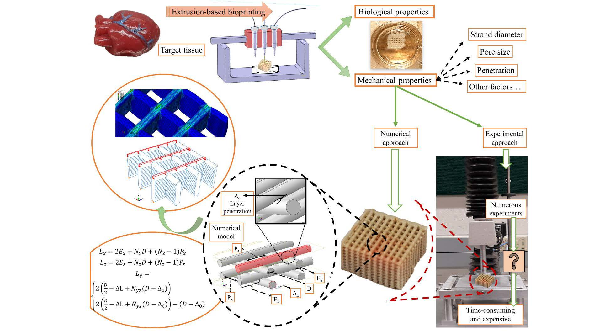
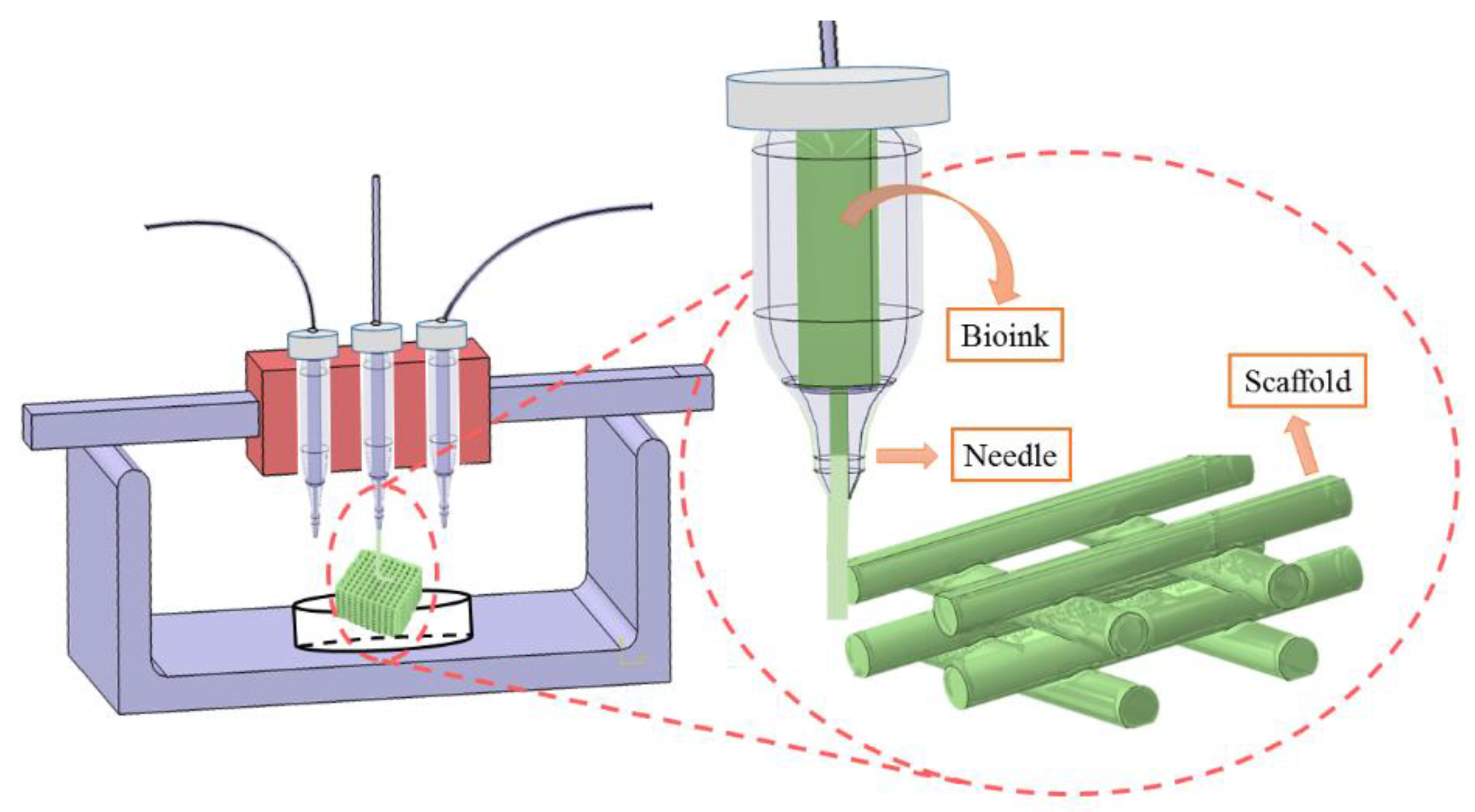
2.2. Design and Fabrication of Scaffolds

A computer-aided-design (CAD) model of a scaffold, with a cuboid shape of 7 × 7 × 5 mm, was generated using Magics EnvisionTEC (V13, Materialise, Leuven, Belgium), which was then sliced into 31 layers with the Bioplotter RP software (V2.9, EnvisionTEC GmbH, Gladbeck, Germany). The slice thickness was considered as 88% of the strand diameter. VisualMachine software (BP, V2.2, EnvisionTEC GmbH, Gladbeck, Germany) was utilized to control the printing and assign the print parameters for the model (Figure 2). A perpendicular pattern with alternating angles of 0° and 90° was used between the two adjacent layers, each layer consisting of strands with a distance of 1 mm. A 3D-BioplotterTM system (EnvisionTEC GmbH, Gladbeck, Germany) was used to fabricate scaffolds by printing alginate solution into the 50 mM CaCl2 solution to induce crosslinking layer-by-layer. Specifically, the 3% alginate solution was maintained at 10 °C for 10 min in a low-temperature dispensing head. Alginate was dispensed at 18–20 °C using a conical needle with the inner diameter of 200 µm. The scaffolds were printed in a 12-well tissue culture plate coated with PEI, with each well containing 1 mL of 50 mM CaCl2 to crosslink alginate immediately after dispensing. The pressure was set at 0.2 bar and head speed of 8 mm/s selected during printing. Printing conditions are presented in Table 1. After fabrication, scaffolds were maintained in the crosslinking solution for a time period sufficient to allow the Ca2+ ions to penetrate and crosslink the whole structure.
For assessing the elastic modulus of bulk gel, bulks of alginate were also created on the 3D-BioplotterTM system by employing the procedure and printing conditions similar to the above scaffold fabrication except the zero distance set between two adjacent strands.

2.3. Image Analyzing

For capturing the geometry of the samples, a 13 MP, f/2.2, 31 mm, autofocus camera (Samsung, Suwon, Gyeonggi-do, South Korea) was used, and images were analyzed by Image J® 1.48v Software (National Institute of Health, Gaithersburg, MD USA). The strand diameter, height, and pore size of the fabricated scaffold were obtained using the aforementioned software (n = 10). Moreover, the projected area on the plane of loading, which is needed for the calculation of stress was obtained using the dimensions obtained from these images prior to performing mechanical testing.

2.4. Mechanical Testing

Using a texture machine (Texture Technologies Corp., New York, NY, USA), uniaxial unconfined compression tests were performed. Three specimens were prepared for each group of bulk alginate and porous scaffold. All tests were carried out at a speed of 0.1 mm/s (strain rate of 0.035 S−1) with a defined preload of 1 N. Before doing any experiment, specimens were placed between the loading plates of the machine and the load cell was set to zero. ASTM D-695 standard was used to assess the elastic modulus of both bulk gels and porous scaffolds of alginate [25], as reported in the standard guide for characterization and testing of biomaterial scaffolds used in tissue-engineered medical products (ASTM: F2150-13) [26]. Porous scaffolds were kept in a CaCl2 crosslinking solution and extracted from the solution immediately prior to mechanical testing. It should be noted that keeping fabricated samples of alginate in the incubator at 37 °C temperature (humidified environment containing 5% CO2) did not have any significant effect on the elastic modulus. Hence, to simplify the experiment, samples were kept in a refrigerator (4 °C) before the experiment. It is noted that there was a nonlinear region at the beginning of the stress-strain curves, termed as the toe-region. This region makes the calculation of the elastic modulus (the slope of the first linear part of the curve) difficult. Based on the method provided in ASTM D-695 standard, a line was used to fit the first linear section of the curves and the intersection of this line and the strain axis is terms as the corrected zero-strain point.

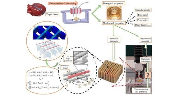
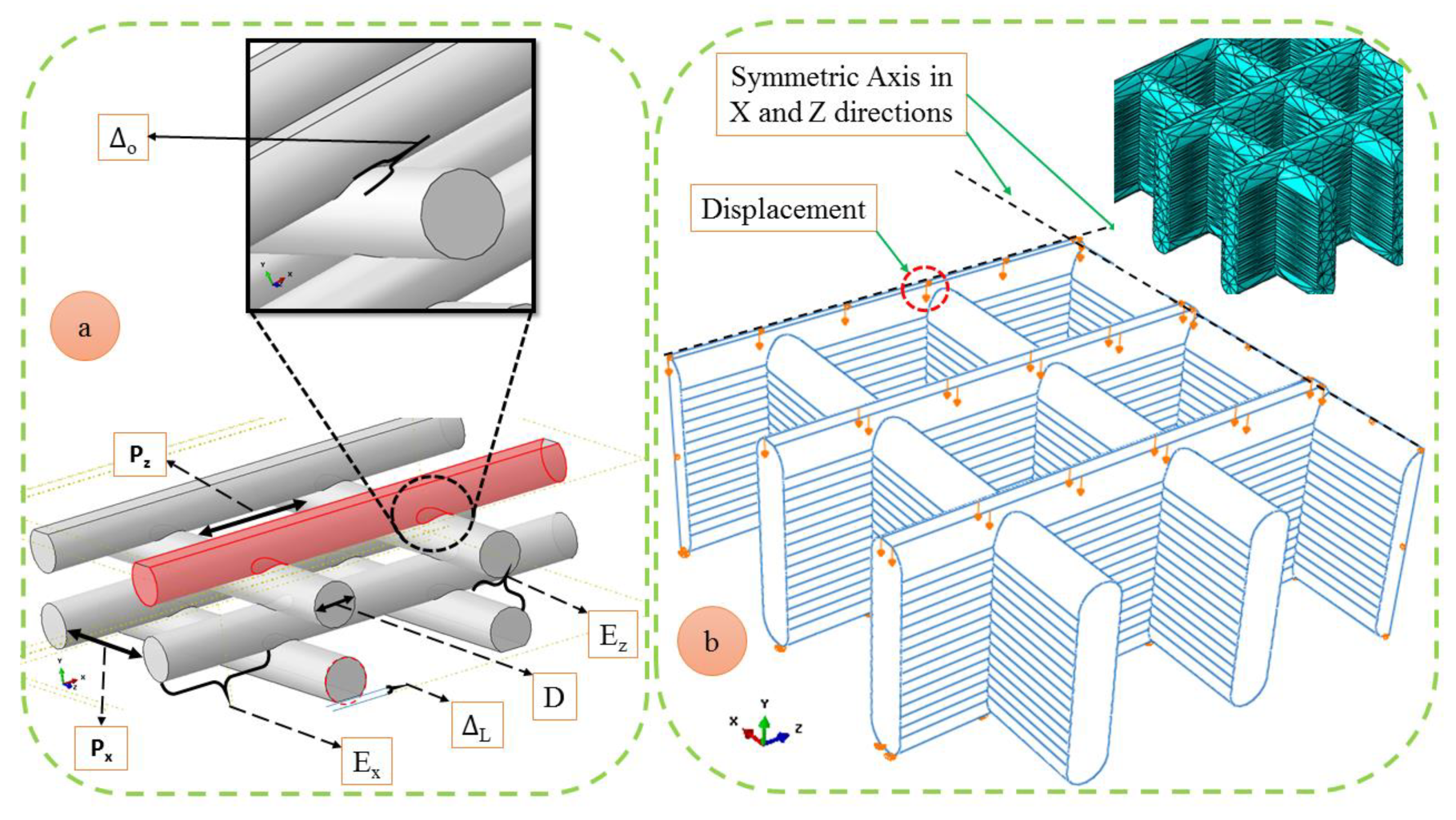
2.5. Finite Element Modeling

A Python script was used to develop a parametric finite element model through the finite element package ABAQUS 6.11-1 with the detailed information provided as follows. Figure 3a shows the model generated using cylinders with the diameter of D and alternating strand orientation of 0–90° to mimic the structure of fabricated scaffolds. The number of strands in each plane is denoted by N with corresponding subscripts, the amount of penetration within layers by Δ₀, the pore size in the X and Z directions by Px and Pz, respectively, and the length of material exceeding the main borders of the scaffold by Ex and Ez (Figure 3a). It should be mentioned that for applying the compressive load, the upper and lower sides of the modeled scaffolds were trimmed with the value of ΔL. Using these parameters, the dimensions of the scaffold can be calculated using the following relationships:
L x = 2 E x + N x D + ( N x 1 ) P x
L z = 2 E z + N z D + ( N z 1 ) P z
L y = { 2 ( D 2 Δ L + N y z   ( D Δ 0 ) )   N y z = N y x 1 2 ( D 2 Δ L + N y z ( D Δ 0 ) ) ( D Δ 0 ) N y z = N y x
where Lx, Ly, and Lz are the length of the scaffold in each direction.
As shown in Figure 3b, to simulate the compression test, all the translational degrees of freedom of the bottom side of the scaffold were fixed while the upper face was moved downward with the value of the desired deformation. Since the model has some symmetric planes, the computational efforts might be reduced by decreasing the size of the model. Hence, the model was considered symmetric in X and Z directions. In addition, appropriate boundary conditions, e.g., fixing the degree of freedom parallel to the plane of symmetry were applied.
To run the developed model, 20% displacement was applied and the Poisson’s ratio was considered as 0.31 as per the previous studies [27,28]. Ten-node modified quadratic tetrahedron elements (four integration points, C3D10) were used to mesh the model (the configuration of the meshed model is available in Figure 3b). In addition, convergence was achieved by using the criteria or conditions that the displacement function within an element is continuous, of rigid-body one, and under the constant strain [29].

2.6. Statistical Analysis

Experimental data are presented as mean ± standard deviation. A linear regression equation was extracted using Minitab® 17.1 software (State College, PA, USA) and confidence level for all intervals was considered as two-sided intervals with 95% value and, thus, p-value less than 0.05 was considered significant.

3. Results and Discussion

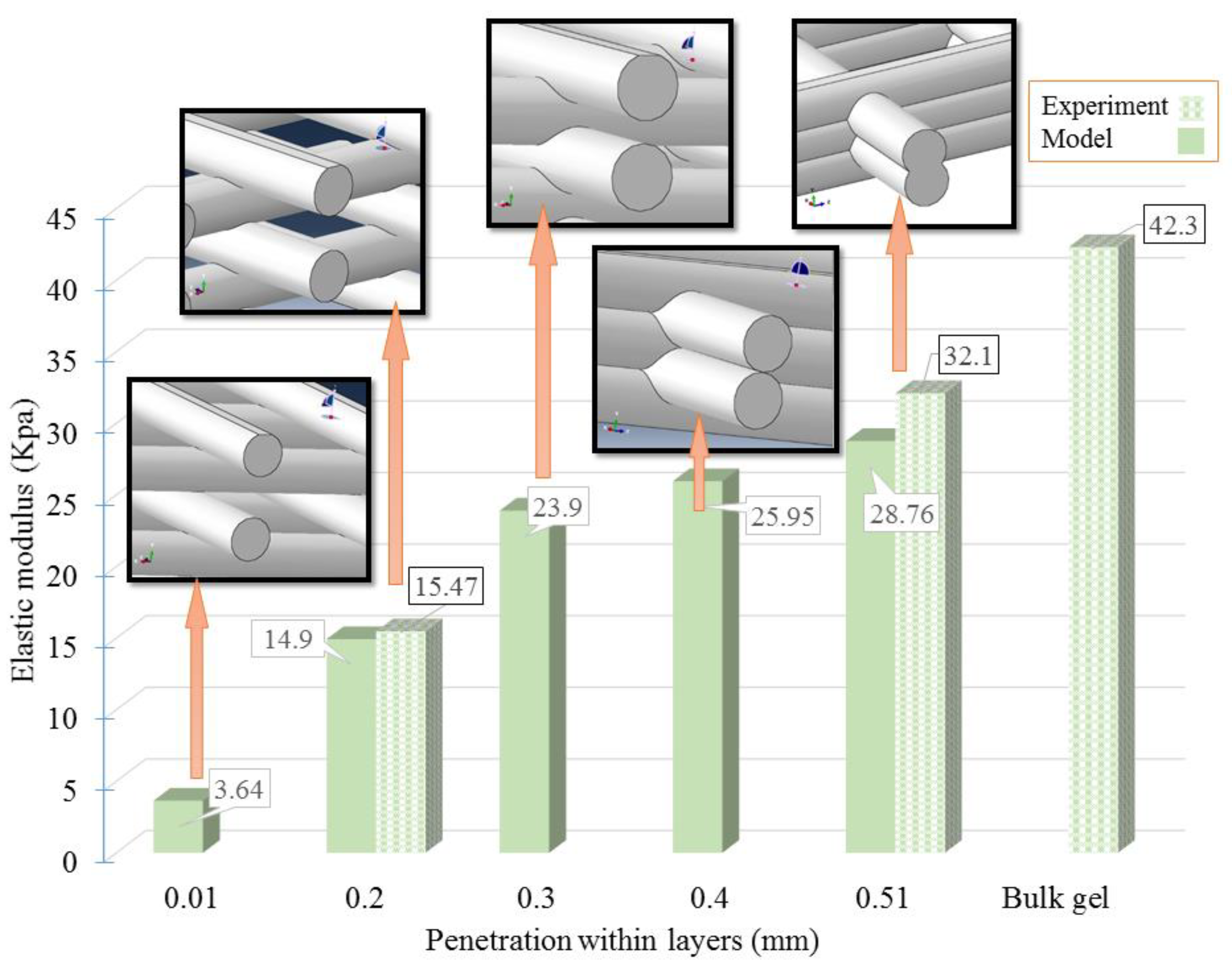
3.1. Model Verification

In this section, the geometrical features of the fabricated scaffold are evaluated according to the analysis of the captured images using Image J® Software, the elastic modulus of bulk gel and porous scaffolds are then examined and reported, and finally the results of the developed finite element model are presented and compared with the experimental measurements.
Geometrical features of scaffolds were measured using captures images analyzed in Image J® Software. The average pore size was 0.39 ± 0.03 mm and 0.47 ± 0.06 mm in Z and X directions, respectively. The strand diameter and height of the scaffold were also measured as 0.58 ± 0.06 mm and 2.63 ± 0.12 mm in Z and X directions, respectively. To measure the penetration, the original CAD design and the printed scaffolds were compared in terms of the layer height. The penetration was calculated based on the difference in heights, giving a value of 510 µm. Table 2 shows the parameters obtained from geometrical features of the fabricated scaffold and they were used in the simulation of the model, as input data.
The compressive stress-strain response of the porous scaffolds and bulk alginate was used to calculate their corresponding elastic modulus. The elastic modulus of the bulk gel and alginate scaffold were calculated to be 42.3 ± 1.58 KPa and 32.1 ± 0.6 KPa, respectively.
For finite element simulations, a mesh sensitivity analysis on the finite element model was performed by comparing the predicted elastic modulus using different mesh sizes, with the results shown in Figure 4. To do so, the mesh size was reduced until the change of the obtained results was negligible. Using this method, the mesh size value of 0.3 was obtained and used for all the simulations.
Using the developed finite element model, the elastic modulus of the fabricated scaffold was predicted to be 28.76 KPa, which is in agreement with the experimentally measured one, i.e., 32.1 ± 0.6 KPa. To further study the effectiveness of the model, more experiments were conducted by changing the penetration, pore size, and number of layers. For this, three sets of experiments were performed and for each set, one factor was subjected to changes and other parameters were taken the same as the ones listed in Table 2.
For the first set, the penetration element was changed. Initially, the slice thickness, which was the subtraction of the 88% of the strand diameter and strand diameter value (i.e., 580 µm), calculated as 70 µm to have 510 µm penetration. Then, the slice thickness was changed to reach 200 µm penetration by trial and error. The model predicted 14.92 KPa for scaffolds with approximately 0.2 mm penetration within layers (the elastic modulus based on the experiment was 15.47 ± 1.03 KPa). As mentioned, the model predicted 28.76 KPa as the elastic modulus of scaffolds with 510 µm penetration which was in good agreement with experimental results (32.1 ± 0.6 KPa), as shown in Figure 5.
For the second set of experiments, the pore size of scaffolds was subjected to changes. Experimental results showed the elastic modulus of 22.43 ± 0.49 KPa for scaffolds with Px = 551 µm and Pz = 487 µm, while the model predicted 21.35 KPa (Figure 6). As it was mentioned, the elastic modulus of scaffolds fabricated based on parameters reported in Table 2 (Px = 470 µm and Pz = 390 µm) was 32.1 ± 0.6 KPa, while the model predicted 28.76 KPa. In addition, for bulk gel, the elastic modulus of 42.3 ± 1.58 KPa was calculated experimentally, while the simulation predicted 37.94 KPa, as the elastic modulus. In the case of a bulk gel, Px = Pz = 0 was considered for the modeling purpose.
For the last set of experiments, the number of layers was changed and scaffolds with 16 and 24 number of layers were printed and experimental results showed 24.25 ± 0.64 KPa and 26.85 ± 0.92 KPa, while model predictions were 24.97 KPa and 27.34 KPa, respectively (Figure 7). As mentioned earlier, for scaffolds fabricated based on parameters mentioned in Table 2, 32.1 ± 0.60 KPa was obtained experimentally as the elastic modulus of scaffolds with 31 layers (the model prediction was 28.76 KPa).

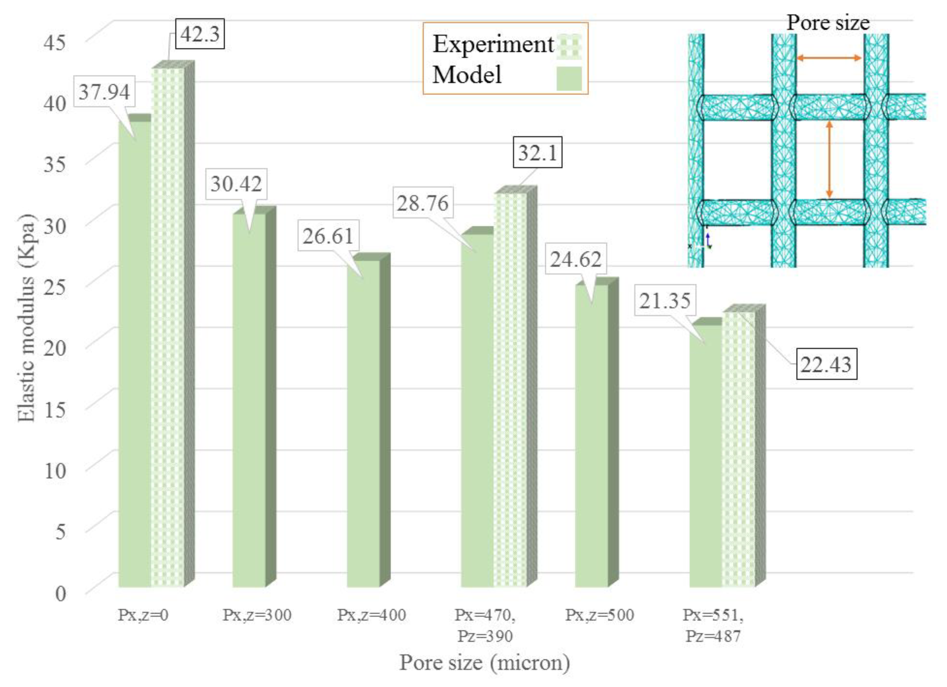
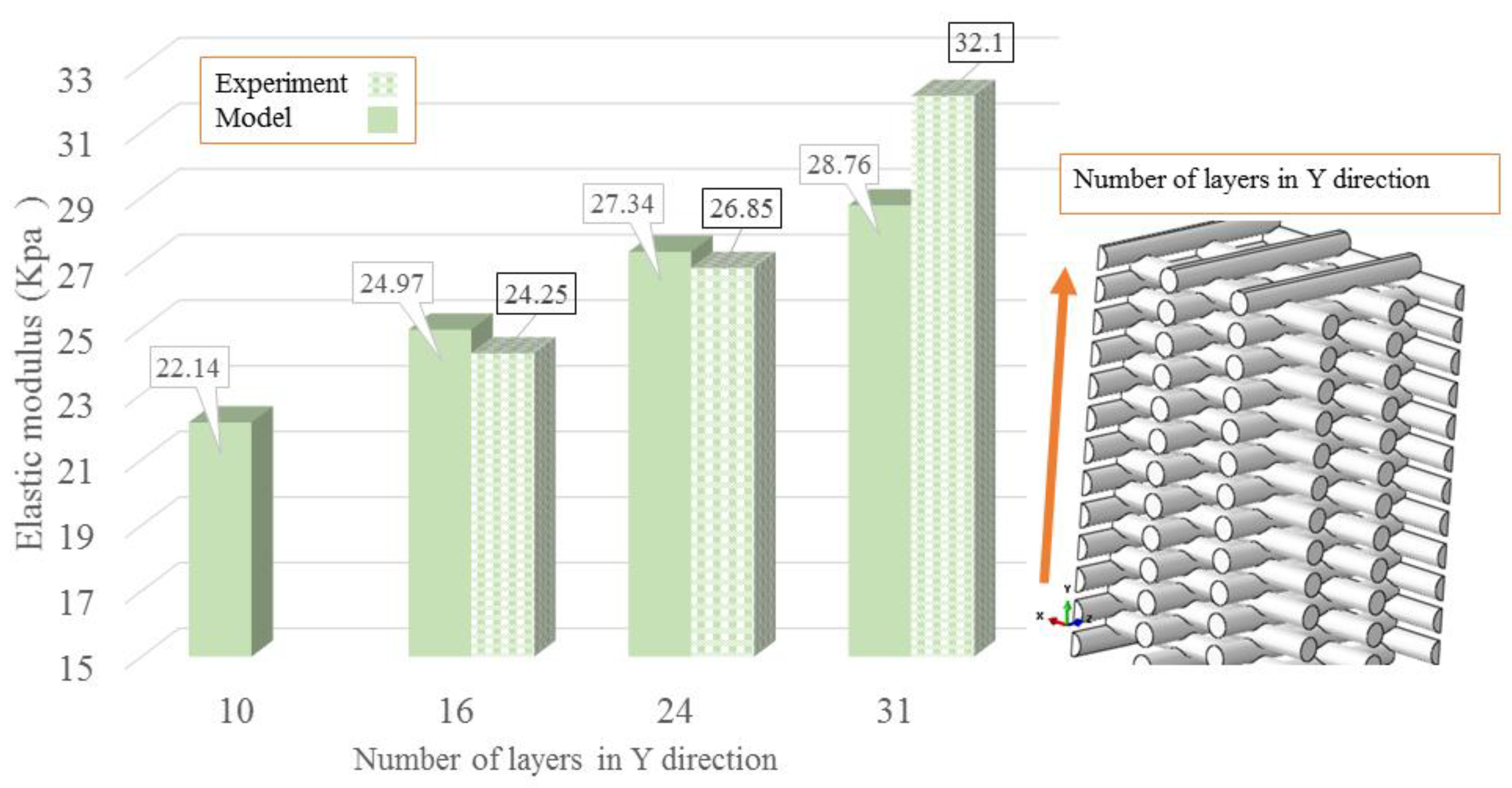
3.2. Some More Simulation Results

Using the developed model, simulations were further performed to study the influence of penetration on the elastic modulus of scaffolds. For this, the value of penetration was changed from 0.01 mm, to 0.2, 0.3, 0.4, and 0.51, while the values of other parameters were taken the same as the ones listed in Table 2. The simulation results are presented in Figure 5, which shows a larger penetration lead to the higher elastic modulus. Elastic modulus achieved from experiment and model were discussed earlier for 0.2 and 0.51 mm penetration (refer to Section 3.1). More simulations were performed and the model predicted 3.64 KPa, 23.9 KPa, and 25.95 KPa for scaffolds with 0.01, 0.3, and 0.4 mm penetration amongst layers. Additionally, as shown in Figure 5, as the penetration is increased, the model predicts higher elastic modulus and results become closer to the elastic modulus of a bulk gel (experimental elastic modulus = 42.3 KPa). It means that by increasing the penetration, a scaffold with a rigid structure and high mechanical stability is obtained.
It should be noted the penetration between layers is an important index to measure the printability of hydrogels (i.e., alginate in the present study) in 3D bioplotting, which is defined as the ability of a hydrogel to form and maintain a 3D structure and characterized by the difference between the printed scaffold structure and the designed one [30,31]. Lager penetration suggests the bigger difference between the printed structure and designed one, thus poorer printability of the hydrogel. In this study, the measured height of the fabricated scaffolds (2.63 ± 0.12 mm) was inputted to the numerical model to predict the elastic modulus of the printed structure (CAD model height was not considered for modeling).
Based on the developed model, a numerical analysis was also carried out to study the effect of pore size on the elastic modulus of scaffolds. In these simulations, the pore size value was changed from 0 to 551 µm, with other parameter values the same as the ones listed in Table 2. The simulation results are shown in Figure 6, showing that a smaller pore size can result in a higher elastic modulus. As such, the pore size of scaffolds can be adjusted in order to obtain the mechanical properties similar to the native tissues. While there are many experimental studies in this regard [19,21], the use of a finite element method would provide a more effective approach to adjust the pore size or other geometrical parameters to achieve the desired mechanical properties. It should be noted that measured pore sizes in different directions of fabricated scaffolds were not the same as shown in Figure 6. Experimental results were reported in Section 3.1 and here more simulations were performed. Modeling results showed 30.42 KPa, 26.61 KPa, and 24.62 KPa for scaffolds with 300, 400, and 500 µm pore sizes in the X and Z directions defined in Figure 3.
The number of layers in the Y direction was investigated to determine the effect of the height of the scaffold on its elastic modulus. The penetration and strand diameter were considered as 0.51 mm and 0.58 mm, respectively. As demonstrated in Figure 7, increasing the number of layers causes a higher elastic modulus numerically and experimentally. This is likely due to having more layers and, consequently, a thicker scaffold with a more mechanically stable structure has a higher elastic modulus. For a scaffold made of 10 layers, the model predicted 22.14 KPa as the elastic modulus of a porous scaffold. As reported in Section 3.1, the model predicted 24.97 KPa, 27.34 KPa, and 28.76 KPa for scaffolds with 16, 24, and 31 layers, respectively.
A strong congruity was observed between experimental and numerically predicted values of elastic modulus. Although the model was developed based on the assumption of a symmetric structure, bioplotted scaffolds might be asymmetric in different directions due to random variables that affect extrusion. This asymmetry might cause an increase in the error between predicted and real values because of numerous variables associated with the 3D biofabrication regulate the structural uniformity and geometry of the scaffold. Fluid viscosity, temperature, dispensing pressure, needle speed, and crosslinker concentration have a profound effect on the strand diameter, porosity, and pore size distribution [24]. In this study, the scaffolds were printed in a static volume of the crosslinking solution of 1 mL and 50 mM CaCl2, the number of available Ca2+ ions in the crosslinking media decreases gradually with the fabrication of successive layers. Such a variable concentration of Ca2+ ions can affect the structure and thus the mechanical properties of the printed scaffolds [32]. As such, the effect of the crosslinker mechanism can be taken into consideration for improving the accuracy of model prediction. Also, fluid viscosity is temperature-dependent and therefore temperature, changing during the printing process, can affect the fluid flow, which is also responsible for degraded structures in the bioplotted scaffolds. Another important factor influencing the mechanical behavior of porous scaffolds is microstructure degradation from the designed one [33,34,35,36]. Thus, in order to enhance the accuracy of numerical models, one way is to identify these changes and degradations and specify them or their effects in the model. Moreover, it was reported that pore distribution and orientation of strands are not stable throughout the printed scaffold and it can influence the mechanical properties of scaffolds [37]. All of these can result in the degradation of the structure of scaffolds, thus affecting the error between the predicted and real values of scaffolds mechanical properties.
According to the results obtained from the developed model, Equation (4) was derived by fitting a linear regression model (R2 = 99.61%) to quantitatively specify the effect of each term on the elastic modulus. For this purpose, the degree of penetration, strand diameter, pore size, and extra materials in X and Z directions, and the number of layers in Y direction were considered in the model. The number of layers in X and Z directions were assumed as five. In addition, considering the effect of major factors (Δ0, D, Pz, Px, Ez, Ex, and Ny), all the interactions amongst the aforementioned factors were considered in the model. Accordingly, with respect to the p-value, some parameters were not appeared to be significant. However, regarding the interaction between various terms, these factors showed a significant effect Significant interactions were identified amongst many factors including penetration*Ny, D*Ny, D*Pz, D*Px, Ny*Pz, and Ny*Px. Figure 8 shows the effect of each factor on the elastic modulus demonstrating the significant effect of different terms on the elastic modulus.
Elastic modulus = ( 136   Δ 0 ) + ( 651.9   D ) ( 10.37   N y ) + ( 2024   P z ) ( 1956   P x ) ( 497.7   E x ) + ( 569   E z ) ( 822   Δ 0 × D ) + ( 98.5   Δ 0   ×   N y ) ( 22463   Δ 0 × P z ) + ( 22209   Δ 0 × P x ) + ( 4982   Δ 0 × E x ) ( 5749   Δ 0 × E z ) ( 49.9   D × N y ) + ( 1357   D × P z ) ( 1796   D × P x ) 31.4
It should also be noted that degradation of the scaffold over time can affect the mechanical properties of scaffolds and in this regard, many studies have been made to predict the mechanical behavior of scaffolds considering the effect of degradation in physiological condition [38,39,40]. In this study, we focused on the effect of penetration without the consideration of scaffold degradation over time. As an improvement of the model presented in this study, the effect of degradation on the mechanical properties of alginate scaffolds might be included in the future. As another extension of the present work, this model can be applied to study the mechanical behavior of hybrid scaffolds printed from more than two biomaterials. Similarly, this model can also be expanded to represent or predict the mechanical behavior of bioplotted scaffolds made from cell-incorporated hydrogels. To this end, cell-incorporated hydrogels can be evaluated mechanically and results can be used as an input of the presented model to predict the mechanical behavior of them.

4. Conclusions

In this study, a novel finite element model, by taking into account of the penetration of strands in one layer into the previous layer, was developed to represent and predict the mechanical properties of scaffolds fabricated by the 3D bioplotting technique. Our experimental results show the penetration within layers has a significant influence on the mechanical properties of printed scaffolds, along with the number of layers and pore size of scaffolds. To these experimental results, the predictions from our model were compared, showing a strong congruity between them. Based on the simulations from the developed model, a simple regression equation was developed to show the effects of penetration, pore size and number of layers on the elastic modulus of printed scaffolds. The method used to develop both finite element model and regression equation for alginate in the present study can also be implemented for other hydrogels so as to achieve the desired mechanical properties in tissue engineering.

Author Contributions

Formal analysis, S.N. and M.R.K.-R.; Funding acquisition, M.R.K.-R. and X.C.; Investigation, S.N., M.D.S., M.R.K.-R., A.D.M., and X.C.; Methodology, S.N., M.D.S., M.R.K.-R., and X.C.; Project administration, S.N. and X.C.; Resources, M.R.K.-R. and X.C.; Software, M.R.K.-R.; Supervision, M.R.K.-R. and X.C.; Validation, S.N., M.D.S., and A.D.M.; Visualization, S.N.; Writing-original draft, S.N.; Writing-review & editing, M.D.S., M.R.K.-R., A.D.M., and X.C.

Funding

This scientific work was supported by the Natural Sciences and Engineering Research Council of Canada (NSERC, grant number RGPIN-2014-05648).

Conflicts of Interest

There is no conflict of interest.

References

  1. Li, M.G.; Tian, X.Y.; Chen, X.B. A brief review of dispensing-based rapid prototyping techniques in tissue scaffold fabrication: Role of modeling on scaffold properties prediction. Biofabrication 2009, 1, 032001. [Google Scholar] [CrossRef] [PubMed]
  2. Sarker, M.; Chen, X.B.; Schreyer, D.J. Experimental approaches to vascularisation within tissue engineering constructs. J. Biomater. Sci. Polym. Ed. 2015, 26, 683–734. [Google Scholar] [CrossRef] [PubMed]
  3. Chen, X.-B.B. Dispensed-Based Bio-Manufacturing Scaffolds for Tissue Engineering Applications. Int. J. Eng. Appl. 2014, 2, 1–31. [Google Scholar]
  4. Naghieh, S.; Badrossamay, M.; Foroozmehr, E.; Kharaziha, M. Combination of PLA Micro-fibers and PCL-Gelatin Nano-fibers for Development of Bone Tissue Engineering Scaffolds. Int. J. Swarm Intell. Evol. Comput. 2017, 6. [Google Scholar] [CrossRef]
  5. Naghieh, S.; Foroozmehr, E.; Badrossamay, M.; Kharaziha, M. Combinational processing of 3D printing and electrospinning of hierarchical poly(lactic acid)/gelatin-forsterite scaffolds as a biocomposite: Mechanical and biological assessment. Mater. Des. 2017, 133, 128–135. [Google Scholar] [CrossRef]
  6. Jin, T.; Stanciulescu, I. Numerical investigation of the influence of pattern topology on the mechanical behavior of PEGDA hydrogels. Acta Biomater. 2017, 49, 247–259. [Google Scholar] [CrossRef] [PubMed]
  7. Naghieh, S.; Reihany, A.; Haghighat, A.; Foroozmehr, E.; Badrossamay, M.; Forooghi, F. Fused Deposition Modeling and Fabrication of a Three-dimensional Model in Maxillofacial Reconstruction. Regen. Reconstr. Restor. 2016, 1, 139–144. [Google Scholar]
  8. Naghieh, S.; Karamooz Ravari, M.R.R.; Badrossamay, M.; Foroozmehr, E.; Kadkhodaei, M. Numerical investigation of the mechanical properties of the additive manufactured bone scaffolds fabricated by FDM: The effect of layer penetration and post-heating. J. Mech. Behav. Biomed. Mater. 2016, 59, 241–250. [Google Scholar] [CrossRef] [PubMed] [Green Version]
  9. Sarker, M.M.; Naghieh, S.; Mcinnes, A.D.A.D.; Schreyer, D.J.D.J.; Chen, X. Strategic Design and Fabrication of Nerve Guidance Conduits for Peripheral Nerve Regeneration. Biotechnol. J. 2018, 1700635. [Google Scholar] [CrossRef] [PubMed]
  10. Naghieh, S.; Sarker, M.; Izadifar, M.; Chen, X. Dispensing-based bioprinting of mechanically-functional hybrid scaffolds with vessel-like channels for tissue engineering applications—A brief review. J. Mech. Behav. Biomed. Mater. 2018, 78, 298–314. [Google Scholar] [CrossRef] [PubMed]
  11. Sarker, M.D.; Naghieh, S.; McInnes, A.D.; Schreyer, D.J.; Chen, X. Regeneration of peripheral nerves by nerve guidance conduits: Influence of design, biopolymers, cells, growth factors, and physical stimuli. Prog. Neurobiol. 2018, in press. [Google Scholar] [CrossRef] [PubMed]
  12. Ariful Islam Sarker, M.; Izadifar, M.; Schreyer, D.; Chen, X. Influence of ionic cross linkers (Ca2+/Ba2+/Zn2+) on the Mechanical and Biological Properties of 3D Bioplotted Hydrogel Scaffolds. J. Biomater. Sci. Polym. Ed. 2018, 29, 1126–1154. [Google Scholar] [CrossRef] [PubMed]
  13. Basu, B. Fundamentals of Scaffolds Fabrication Using Low Temperature Additive Manufacturing. In Biomaterials for Musculoskeletal Regeneration; Springer: Berlin, Germany, 2017; pp. 127–173. [Google Scholar]
  14. Das, S.; Pati, F.; Choi, Y.-J.; Rijal, G.; Shim, J.-H.; Kim, S.W.; Ray, A.R.; Cho, D.-W.; Ghosh, S. Bioprintable, cell-laden silk fibroin–gelatin hydrogel supporting multilineage differentiation of stem cells for fabrication of three-dimensional tissue constructs. Acta Biomater. 2015, 11, 233–246. [Google Scholar] [CrossRef] [PubMed]
  15. Singh, B.K.; Sirohi, R.; Archana, D.; Jain, A.; Dutta, P.K. Porous chitosan scaffolds: A systematic study for choice of crosslinker and growth factor incorporation. Int. J. Polym. Mater. Polym. Biomater. 2015, 64, 242–252. [Google Scholar] [CrossRef]
  16. Heo, D.N.; Castro, N.J.; Lee, S.-J.; Noh, H.; Zhu, W.; Zhang, L.G. Enhanced bone tissue regeneration using a 3D printed microstructure incorporated with a hybrid nano hydrogel. Nanoscale 2017, 9, 5055–5062. [Google Scholar] [CrossRef] [PubMed] [Green Version]
  17. Izadifar, Z.; Chang, T.; Kulyk, W.M.; Chen, D.; Eames, B.F. Analyzing biological performance of 3D-printed, cell-impregnated hybrid constructs for cartilage tissue engineering. Tissue Eng. Part C Methods 2016, 22, 173–188. [Google Scholar] [CrossRef] [PubMed]
  18. Lee, K.Y.; Mooney, D.J. Alginate: Properties and biomedical applications. Prog. Polym. Sci. 2013, 37, 106–126. [Google Scholar] [CrossRef] [PubMed]
  19. You, F.; Wu, X.; Chen, X. 3D Printing of Porous Alginate/gelatin Hydrogel Scaffolds and Their Mechanical Property Characterization. J. Int. J. Polym. Mater. Polym. Biomater. 2016, 66, 299–306. [Google Scholar] [CrossRef]
  20. Bracaglia, L.G.; Smith, B.T.; Watson, E.; Arumugasaamy, N.; Mikos, A.G.; Fisher, J.P. 3D printing for the design and fabrication of polymer-based gradient scaffolds. Acta Biomater. 2017, 56, 3–13. [Google Scholar] [CrossRef] [PubMed]
  21. Olubamiji, A.D.; Izadifar, Z.; Si, J.L.; Cooper, D.M.L.; Eames, B.F.; Chen, D.X. Modulating mechanical behaviour of 3D-printed cartilage-mimetic PCL scaffolds: Influence of molecular weight and pore geometry. Biofabrication 2016, 8, 025020. [Google Scholar] [CrossRef] [PubMed]
  22. Naghieh, S.; Ravari, M.R.K.; Badrossamay, M.; Foroozmehr, E.; Kadkhodaei, M. Finite element analysis for predicting the mechanical properties of bone scaffolds fabricated by fused deposition modeling (FDM). In Modares Mechanical Engineering, Proceedings of the Advanced Machining and Machine Tools Conference, Tehran, Iran, 4–5 November 2015; Tarbiat Modares University Press: Tehran, Iran, 2015; Volume 15, pp. 450–454. [Google Scholar]
  23. Bawolin, N.K. Modeling Material-Degradation-Induced Elastic Property of Tissue Engineering Scaffolds. J. Biomech. Eng. 2010, 132, 111001. [Google Scholar] [CrossRef] [PubMed]
  24. Sarker, M.; Chen, X.B. Modeling the flow behavior and flow rate of medium viscosity alginate for scaffold fabrication with a 3D bioplotter. J. Manuf. Sci. Eng. 2017, 139, 081002. [Google Scholar] [CrossRef]
  25. ASTM: D 695 15, Standard Test Method for Compressive Properties of Rigid Plastics; ASTM International: West Conshohocken, PA, USA, 2015.
  26. ASTM: F1635, Standard Guide for Characterization and Testing of Biomaterial Scaffolds Used in Tissue-Engineered Medical Products; ASTM International: West Conshohocken, PA, USA, 2013.
  27. Nguyen, V.B.; Wang, C.X.; Thomas, C.R.; Zhang, Z. Mechanical properties of single alginate microspheres determined by microcompression and finite element modelling. Chem. Eng. Sci. 2009, 64, 821–829. [Google Scholar] [CrossRef]
  28. Zhang, Y.; Yu, Y.; Chen, H.; Ozbolat, I.T. Characterization of printable cellular micro-fluidic channels for tissue engineering. Biofabrication 2013, 5, 025004. [Google Scholar] [CrossRef] [PubMed] [Green Version]
  29. Module: 2 Finite Element Formulation Techniques Lecture 3: Finite Element Method: Displacement Approach. Available online: https://nptel.ac.in/courses/105105041/m2l7.pdf (accessed on 20 July 2018).
  30. He, Y.; Yang, F.; Zhao, H.; Gao, Q.; Xia, B.; Fu, J. Research on the printability of hydrogels in 3D bioprinting. Sci. Rep. 2016, 6, 29977. [Google Scholar] [CrossRef] [PubMed] [Green Version]
  31. You, F.; Eames, B.F.; Chen, X. Application of Extrusion-Based Hydrogel Bioprinting for Cartilage Tissue Engineering. Int. J. Mol. Sci. 2017, 18, 1597. [Google Scholar] [CrossRef] [PubMed]
  32. Naghieh, S.; Karamooz-Ravari, M.R.; Sarker, M.; Karki, E.; Chen, X. Influence of crosslinking on the mechanical behavior of 3D printed alginate scaffolds: Experimental and numerical approaches. J. Mech. Behav. Biomed. Mater. 2018, 80, 111–118. [Google Scholar] [CrossRef] [PubMed] [Green Version]
  33. Karamooz Ravari, M.R.; Kadkhodaei, M.; Badrossamay, M.; Rezaei, R. Numerical investigation on mechanical properties of cellular lattice structures fabricated by fused deposition modeling. Int. J. Mech. Sci. 2014, 88, 154–161. [Google Scholar] [CrossRef]
  34. Karamooz Ravari, M.R.; Kadkhodaei, M.; Ghaei, A. A Unit Cell Model for Simulating the Stress-Strain Response of Porous Shape Memory Alloys. J. Mater. Eng. Perform. 2015, 24, 4096–4105. [Google Scholar] [CrossRef]
  35. Ravari, M.R.K.; Kadkhodaei, M.; Ghaei, A. Effects of asymmetric material response on the mechanical behavior of porous shape memory alloys. J. Intell. Mater. Syst. Struct. 2016, 27, 1687–1701. [Google Scholar] [CrossRef]
  36. Karamooz Ravari, M.R.; Kadkhodaei, M. A Computationally Efficient Modeling Approach for Predicting Mechanical Behavior of Cellular Lattice Structures. J. Mater. Eng. Perform. 2015, 24, 245–252. [Google Scholar] [CrossRef]
  37. Singh, R.; Lee, P.D.; Lindley, T.C.; Kohlhauser, C.; Hellmich, C.; Bram, M.; Imwinkelried, T.; Dashwood, R.J. Characterization of the deformation behavior of intermediate porosity interconnected Ti foams using micro-computed tomography and direct finite element modeling. Acta Biomater. 2010, 6, 2342–2351. [Google Scholar] [CrossRef] [PubMed]
  38. Bawolin, N.K.; Chen, X. Synchrotron-Based in Situ Characterization of the Scaffold Mass Loss from Erosion Degradation. J. Funct. Biomater. 2016, 7, 17. [Google Scholar] [CrossRef] [PubMed]
  39. Bawolin, N.K.; Dolovich, A.T.; Chen, D.X.B.; Zhang, C.W.J. Characterization of mechanical properties of tissue scaffolds by phase contrast imaging and finite element modeling. J. Biomech. Eng. 2015, 137, 81004. [Google Scholar] [CrossRef] [PubMed]
  40. Bawolin, N.K.; Chen, X.B. Remote Determination of Time-Dependent Stiffness of Surface-Degrading-Polymer Scaffolds via Synchrotron-Based Imaging. J. Biomech. Eng. 2017, 139, 41004. [Google Scholar] [CrossRef] [PubMed]
Figure 1. Schematic of 3D bioplotting.
Applsci 08 01422 g001
Figure 2. Illustration of printing alginate scaffolds: (a) computer-aided-design (CAD) model; (b) sliced layers; and (c) 3D-Bioplotter used for scaffold printing, with an inserted image showing the alginate scaffold printed in a tissue culture plate.
Applsci 08 01422 g002
Figure 3. (a) Applied parameters in finite element model including the amount of penetration within layers (Δ0), pore size in the X and Z directions (Px and Pz), Ex and Ez as the extra material exceeding the main borders of the scaffold. ΔL is also the amount of trimmed value of the upper and lower sides of the modeled scaffolds for applying the compressive load and D is the strand diameter and (b) applied boundary conditions and meshed part.
Applsci 08 01422 g003
Figure 4. Mesh sensitivity study.
Applsci 08 01422 g004
Figure 5. Effect of penetration within layers on the elastic modulus of alginate scaffolds with a strand diameter of 0.58 mm and a distance of 1 mm between two adjacent strands.
Applsci 08 01422 g005
Figure 6. Effect of pore size on the elastic modulus (pattern fill column bars show experimental results for bioplotted scaffolds with (Px,z = 0), (Px = 470 and Pz = 390), and (Px = 551 and Pz = 487)).
Applsci 08 01422 g006
Figure 7. Effect of the number of layers on the elastic modulus (pattern fill column bars show experimental results for bioplotted scaffolds with 16 (24.25 ± 0.64 KPa), 24 (26.85 ± 0.92 KPa), and 31 layers (32.1 ± 0.60 KPa)).
Applsci 08 01422 g007
Figure 8. Effect of (a) Δ0 and Ny; (b) Δ0 and D; (c) Ex and Ez; and (d) Pz and Px on the elastic modulus (EM).
Applsci 08 01422 g008
Table 1. Printing condition used in scaffold fabrication.
ConcentrationNeedle Diameter (µm)Head Speed (mm/s)Pressure (bar)Temperature (°C)Crosslinker
3% (w/v)20080.218–20CaCl2 (50 mM)
Table 2. Parameter values used in simulation by the finite element model.
ParametersValues (µm)
Nx7
Nyx15
Nyz16
Nz7
D580
Δ 0510
Δ L10
Px470
Pz390
Ex10
Ez10

