Article

Implementation of Backward Surface Waves by Multilayered Metal-Dielectric Metamaterials Partnering with Conventional Dielectric Media

Department of Physics, Harbin Institute of Technology, Harbin 150001, China
*
Author to whom correspondence should be addressed.
Appl. Sci. 2018, 8(9), 1420; https://doi.org/10.3390/app8091420
Submission received: 31 July 2018 / Revised: 14 August 2018 / Accepted: 16 August 2018 / Published: 21 August 2018
(This article belongs to the Special Issue Sub-wavelength Optics)

Abstract

:
It has been reported that backward surface waves of Tamm state can be supported by a multilayered metal–dielectric metamaterial with different partner materials, such as left-handed metamaterial or dissimilar metallic–dielectric metamaterial. In this paper, the transfer-matrix method is employed to reveal that transverse-magnetic (TM)-polarized backward surface waves can be realized by a multilayered metal–dielectric metamaterial in contact with a conventional homogenous dielectric medium. Owing to the strong optical nonlocality, the existence of such backward surface waves is proved to be dependent on the order of the metallic/dielectric layers. The relevant anomalous dispersion relations can also be dramatically engineered by varying the unit-cell thickness and the filling factor. Additionally, the distribution of the energy flow is presented to further unfold the physical mechanism of the backward surface waves. Finally, a numerical simulation of backward surface wave excited by a TM-polarized Gaussian beam based on a prism-coupled configuration is displayed.

Graphical Abstract

1. Introduction

Optical surface waves (SWs), which are a special class of electromagnetic waves propagating along the interface of two dissimilar materials with fields decaying exponentially away from the interface, have been extensively studied in the last century. Owing to their characteristics of field enhancement [1] and localization [2], and high sensitivity in partner materials [3], SWs have shown promising potential in many applications, such as optical sensing [4], integrated optics [5], nano-optical tweezers [6], microscopy [7] and communication [8].
However, the introduction of these SWs is difficult since the fields of SWs should be evanescent in both partner media with Maxwell’s equations satisfied at the boundary simultaneously. Typically, SWs can be realized when the partner media have opposite signs of dielectric functions [1], which leads to surface plasmon polaritons (SPPs) [9], or at least one of the partner media is anisotropic, which leads to Dyakonov SWs [10,11], or one of the partner media is periodically inhomogeneous in the direction normal to the interface, which leads to Tamm SWs [12,13]. With the prosperity of nanotechnology in the last two decades, manufactured metamaterials, including shallow metallic gratings [14], pillar structures [15] and multilayers [16], provide more possibilities for new types of SWs, such as Dyakonov plasmons [17], which take over traits from both Dyakonov SWs and SPPs [18], and Dyakonov–Tamm waves [19,20], which combine the aspects of Dyakonov and Tamm SWs. It should be noted that most of these types of SWs are forward waves, in which the vector of energy flow and the corresponding wave share the same direction. Reports on backward SWs, of which the direction of energy flow is opposite to the wave vector, are relatively limited. However, backward SWs possess particular properties, such as high potential in surface-plasmon-based guiding structures [21], and can be directly demonstrated by the electromagnetic field detection around the photonic crystal surface with a local probe [22]. To fully take advantages of backward SWs, further investigation is required.
The multilayered metal–dielectric metamaterials (MMDMs), which are artificial one-dimensional composites of periodically alternating dielectric and metallic layers, can be engineered so as to constitute an ideal platform for the implementation of unconventional surface states. SWs guided by a homogeneous dielectric medium and an MMDM [23,24] can be regarded as a generalization of Tamm state, when the metallic and dielectric layers of the MMDM are parallel to the interface separating the two materials [25]. Electromagnetic analogue of Tamm state localized at the interface of different partner media has been extensively researched, including two dissimilar photonic crystals [26], an MMDM in contact with a left-handed metamaterial [27], two dissimilar MMDMs [28], or a hyperbolic metamaterial heterostructure consisting of stacked graphene sheets separated by dielectric layers [29]. Under the condition of long-wavelength approximation [30,31], MMDMs are conventionally homogenized as uniaxial media through the effective media approximation (EMA) [32,33,34], which simplifies the procedure of analyzing the electromagnetic response of the MMDMs and provides an intuitive physical insight. Nevertheless, the description of MMDMs through the EMA method is incomplete, as the actual periodicity of MMDMs is not taken into account under the homogenization. It has been reported that both the thickness [35] and the order [24] of the metallic and dielectric layers have significant influence on the optical nonlocality of MMDMs due to the excitation of SPPs, thus resulting in the dispersions and diffraction properties of SWs supported by MMDMs that may severely deviate from the results acquired by the EMA method. In particular, additional backward SWs beyond the prediction of EMA method arise [28].
In this paper, we demonstrate that transverse-magnetic (TM)-polarized backward SWs can also be implemented by a conventional homogenous dielectric medium in contact with an MMDM. In the first part of our study, anomalous dispersion relations, negative group velocities and a relevant frequency range of the backward SWs, which are intimately associated with the unit-cell thickness, the filling factor and the order of the metallic layer, are investigated through the rigorous transfer-matrix method [36,37]. Moreover, the physical mechanism of the backward SWs is unraveled by analyzing the distribution of the energy flow in the vicinity of the interface. In the second part of our study, verification of our demonstration is carried out when putting into practice deploying a numerical simulation of a backward SW excited by a TM-polarized Gaussian beam based on a prism-coupled configuration through the finite-element method. Additionally, a simulation of a forward SW is also presented for comparison.

2. Theoretical Modal and Transfer-Matrix Method for TM-polarized Surface States

The geometry of a system formed by a periodic MMDM in contact with a homogenous isotropic dielectric medium is depicted in Figure 1. The partner dielectric medium fills the space of y > 0 while the MMDM fills the space of y < 0 . The permittivities and thicknesses of the two alternating layers are ε p , L p (blue region) and ε q , L q (yellow region) respectively. The thickness of one unit cell is represented by L = L p + L q . For the case of the upper dielectric layer (UDL) being adjacent to the partner medium, p = d , q = m , while for the case of upper metallic layer (UML) being adjacent to the partner medium, p = m , q = d . Here, the subscripts m and d represent the metallic and dielectric layers, respectively. We defined f = L m / L as the filling factor of the metallic layer, and the permittivity of the metallic layer described by ε m = 1 1 / Ω 2 was acquired by the Drude model, neglecting the effect of losses with relative frequency Ω = ω / ω p , where ω p and ω are the plasma frequency and the frequency of wave in vacuum, respectively. The plasma wavelength can be written as λ p = 2 π c / ω p , where c is the light velocity in vacuum. The non-dispersive dielectric layers are PbS, which has a relatively large permittivity ( ε d = 18.8 ) and has been used in the similar multilayer metamaterials according to a previous report [29]. Without loss of generality, the non-dispersive partner medium was set as air with a relative permittivity ε i = 1 . The wave vector of the SWs k S W = ( β , 0 , 0 ) is along the x axis, where β is the propagation constant of the SWs.
Next, we derived the dispersion equation of TM-polarized SWs supported by an MMDM and a homogenous dielectric medium based on the transfer-matrix method. The electromagnetic field of plane waves in single layer j ( j = d , m ) of the MMDM can be written as:
E j ± = E 0 j ± exp [ i k 0 ( ± α j y + β j x ) i ω t ] ,
H j ± = k j ± × E j ± ,
where the wave vector k j ± = k 0 ( β j , ± α j , 0 ) , and α j and β j are the projections of k j ± on the y and x axes in the unit of k 0 , respectively. The ± sign represents the positive and negative running waves along the y axis and E 0 j ± is the polarization vector, E j ± is in the x - y plane while H j ± is along the z axis. Owing to the momentum conservation principle, the tangential component of the wave vector along the x axis in both dielectric and metallic layers should remain the same as the propagation constant of the SWs, that is, β d = β m = β . The normal component along y axis can be written as:
α j = ε j β 2 .
The transfer matrix of single layer j for TM polarization can be given by [38]:
M ^ j = ( cos Φ j i γ j sin Φ j i γ j sin Φ j cos Φ j ) ,
where Φ j = k 0 α j L j and γ j = α j z 0 / ε j . z 0 = μ 0 / ε 0 is the impedance of free space. From Equation (4), we obtained the transfer matrix for a period of the MMDM as:
M ^ p = M ^ d M ^ m ,
in the UDL case, or
M ^ p = M ^ m M ^ d ,
in the UML case. The Bloch wave number K can be derived through the following equation [12]:
e i K L = 1 2 [ ( M p 11 + M p 22 ) + ( M p 22 M p 11 ) 2 + 4 M p 12 M p 21 ] ,
where M p 11 , M p 12 , M p 21 , M p 22 are the four components of the 2 × 2 matrix M ^ p . To fulfill the condition of surface confinement of SWs, the Bloch wave number K should contain a positive imaginary part, and hence the field will decay in the MMDM. The impedances of the Bloch waves can be evaluated as:
Z M M D M = e i K L M p 11 M p 12 .
For the homogenous isotropic medium, the impedance can be expressed as:
Z i = z 0 ε i β 2 ε i .
From Equations (8) and (9), and according to the tangential field continuity, the dispersion relations of the TM-polarized SWs can be obtained by:
Z M M D M = Z i .
In view of Equation (10), we can numerically calculate the group velocities of the SWs by using:
v g = d ω ( β ) d β = ω p d Ω ( β ) d β .

3. Dispersion Relations, Group Velocities and Frequency Range of Backward Surface Waves

In accordance with the transfer-matrix method, we depicted the dispersion relations of the TM-polarized surface states with a metallic layer filling factor f = 0.7 for the case of UDL, as shown in Figure 2a. In contrast, the dispersion curve of the SWs obtained through the EMA method, and one of the conventional SPPs at a metal–dielectric interface are also presented. Even in the condition, in which the unit-cell thickness is far smaller than the plasma wavelength ( L = 0.01 λ p ), the dispersion curves acquired by the transfer-matrix method and the EMA method match each other only when the frequency is evidently below the pole frequency Ω E , at which the propagation constant tends to infinity according to the EMA method. Otherwise, when the frequency is in the vicinity of Ω E , the difference between dispersion curves obtained by the transfer-matrix method and the EMA method becomes significant. The propagation constant tends to infinity at Ω S , which is the bulk plasmon frequency of the conventional SPPs and satisfies ε m ( Ω S ) + ε d = 0 , instead of Ω E . There is a redshift of the dispersion curve calculated by the transfer-matrix method relative to that calculated by EMA method. More importantly, part of the former is anomalously dispersive, thus leading to negative group velocities, as shown in Figure 2b. Hence, the SWs in this condition are backward waves, of which the actual energy propagation direction is opposite to the wave vector.
According to Figure 2a, for smaller propagation constant β close to the light line, the field variation within one unit cell can be regarded as quasi-static. Therefore, relevant dispersions keep consistent with the prediction of the EMA method. However, for larger β , when the wavelength of the SWs is roughly ten times larger than the unit-cell thickness L , the optical nonlocality effect, that is, the field variation within one unit cell becomes much more intensive, appears due to the excitation of surface plasmon modes; thus, the responding dispersions are beyond the EMA method. Under this circumstance, when L is rather small, not exceeding 10% of the plasma wavelength λ p , the coupling of the surface plasmon modes is relatively strong, leading to the anomalous dispersions. The upper threshold frequency Ω up of the anomalous dispersions can be located for the corresponding group velocity v g = 0 , as shown in Figure 2b, while the lower threshold frequency Ω low is equal to Ω S . With L increased above 10% of λ p , the coupling of the surface plasmon modes weaken; thus, the corresponding dispersion curve turns back into the normal dispersion before β tends to infinity at Ω S . In this case, Ω low is inferior to Ω S . In both cases, the width of the anomalous dispersion frequency range always shrinks with the increasing L , as shown in Figure 2c. When L is above 40% of λ p , the whole curve becomes normal dispersive, indicating that backward SWs are prohibited. In the limiting case with an extremely large L , the plasmon modes become uncoupled, and hence, the dispersion curve eventually coincides with the one of the conventional SPPs excited at a single interface between a semi-infinite metal and a PbS dielectric medium. Moreover, the sensitivity of Ω up modulated by L is within 0.28 ω p / λ p ~ 0.34 ω p / λ p (0.82 THz/nm~0.99 THz/nm for λ p = 320   nm ), while the one of Ω low is within 0 ~ 0.1 ω p / λ p (0~0.29 THz/nm for λ p = 320   nm ).
The dispersion relations of the backward SWs can also be modulated by changing the filling factor f in the UDL case. In Figure 3, we presented the dispersion relations, relevant group velocities and anomalous dispersion frequency range of the TM-polarized surface states with different filling factors when the unit-cell thickness was set as L = 0.3 λ p . For f above 0.87, the dispersion curve unfolds normal dispersive when β is in the vicinity of the light line. With the increasing β , once the frequency reaches Ω up , the dispersion curve becomes anomalous dispersive until it is cut off at Ω S with related β achieving infinity. When f is within the range of 0.64–0.87, the lower threshold frequency Ω low of the anomalous dispersion is smaller than Ω S . Yet, the whole dispersion curve always maintains normal dispersive with f lower than 0.64. In general, regardless of the unit-cell thickness, the filling factor should surpass 0.5 in order to support anomalous dispersion relations.
For the EMA method, the dispersion relations are independent of the order of the dielectric and metallic layers, as the effective permittivity tensors of the MMDM in both the UDL and UML cases remain the same. However, different orders of dielectric and metallic layers may lead to different surface plasmon modes, which will cause further impact on the dispersions of the surface states. Therefore, the order of the metallic and dielectric layers may be a key factor for the existence of backward SWs. In Figure 4, we showed the dispersion relations of TM-polarized surface state in the UML case while keeping other conditions unchanged. Compared to the UDL case, there is a blue shift of the dispersion curves calculated by the transfer-matrix method from one of the EMA method. Under such a circumstance, though still being affected by both the unit-cell thickness and filling factor, the dispersion relations maintain normal dispersive. Moreover, in the limiting case with an extremely large unit-cell thickness, the dispersion curve tends to coincide with that of the SPPs excited at a single interface of a semi-infinite metal and air, due to the absence of coupling effect.
In Figure 5, we displayed the profiles of the tangential components H t of the magnetic field and the time-averaged Poynting vector S t according to the propagation constants and related frequencies acquired at Points A and B in Figure 2a and Point C in Figure 4a. For the UDL case, the field is confined at the boundary between the dielectric and metallic layers of the first bilayer unit, which is adjacent to the partner medium, as shown in Figure 5a,c. Hence, the optical nonlocality in this case is mainly caused by the surface plasmon modes excited at the boundary between the dielectric and metallic layers. However, for the UML case, optical nonlocality is mostly due to the surface plasmon modes at the boundary between the upper metallic layer and the partner medium according to the location of the field confinement shown in Figure 5e. In addition, from Figure 5b,d,f, it should be noted that S t remains positive in the dielectric layers and the partner dielectric medium but negative in the metallic layers, indicating that the energy flow in the dielectric layers and the partner dielectric medium is in the same direction with the wave vector of the SW, while the energy flow in the metallic layers is opposite to the direction of the wave vector of the SW. For the anomalous dispersive SW shown in Figure 5b, the energy flow in metallic layers is dominant; therefore, the SW unfolds backward wave characteristics. On the contrary, for the normal dispersive SWs shown in Figure 5d,f, the energy flow in the partner dielectric medium predominates; thus, these SWs unfold forward wave characteristics.

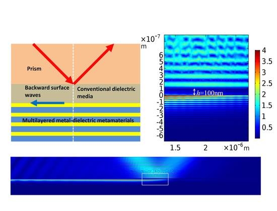
4. Numerical Simulations of Backward Surface Waves Excited by a TM-Polarized Gaussian Beam Based on the Prism-Coupled Configuration

The prism-coupled configuration has been widely used in the excitation of various types of surface modes, such as SPPs [9], Dyakonov SWs [11] and Dyakonov–Tamm waves [20]. Our aim in this section is to verify the backward SWs of anomalous dispersion relations based on a prism-coupled configuration through the finite-element method. As depicted in Figure 6, a prism with a large refraction index n p is placed onto the partner medium with a confined thickness h . Both the permittivities of the partner medium and the dielectric layers remain unchanged. Additionally, we extended the simulation to a more practical case when the permittivity of the metallic layers becomes complex in the Drude form as ε m = 1 ω p 2 / [ ω ( ω + i Γ ) ] [39], considering the metallic losses. Here, Γ is the damping coefficient, which is assumed to be 1 × 10 11   s 1 for low loss metallic material. In this condition, the imaginary part of the metallic permittivity only leads to a limited propagation length of the SWs, while corresponding dispersion relations calculated in the last section remain unchanged as the phase transition in the metallic layers is still insignificant [39]. A Gaussian beam with a beam waist G w radiates obliquely from the prism to the partner medium, and the SWs can be excited in the vicinity of the interface separating the MMDM and the partner medium (at the x - z plane in Figure 6) by properly modulating h . In principle, this scenario is able to occur only if the tangential wave vector component of the Gaussian beam equals to the propagation constants of the SWs.
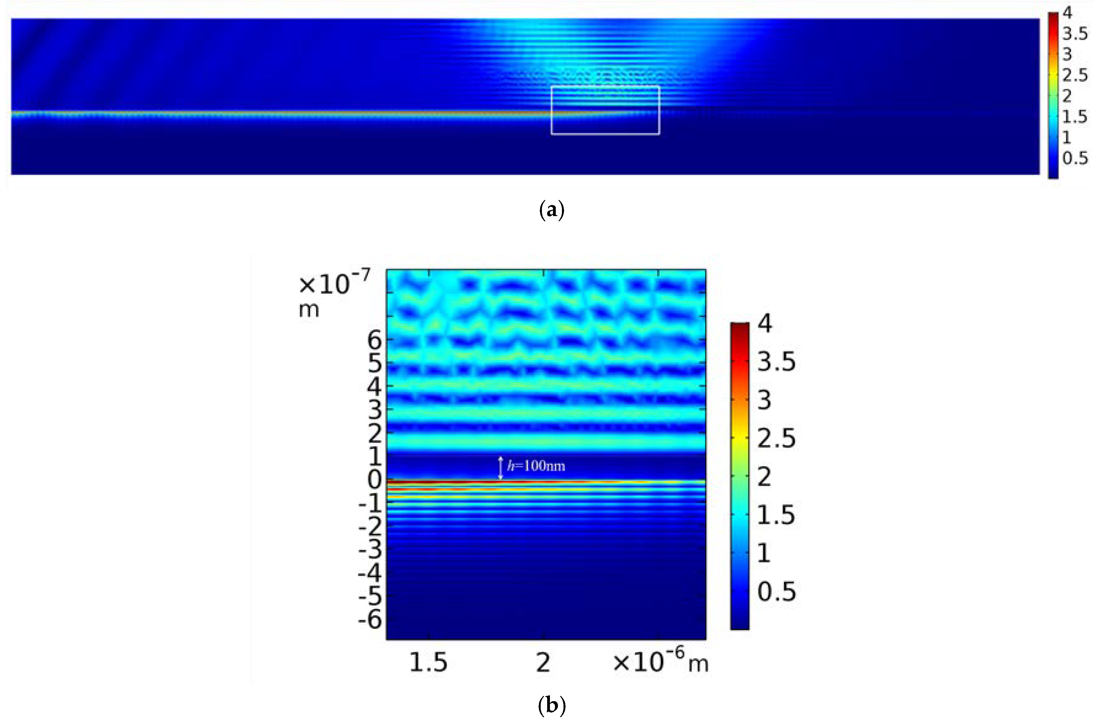
Figure 7a displays the magnetic field distribution of the backward SW with the propagation constant and related frequency acquired at Point A of the dispersion curve in Figure 2a. By properly adjusting the thickness of the partner dielectric medium, the light beam of the SW can be on the same side of the normal with the incident beam, which is similar to the negative refraction phenomenon, revealing the fact that the direction of the energy flow is opposite to the wave vector of the SW along the x axis. Moreover, according to the magnification of the white rectangle, as shown in Figure 7b, the field distributed in the MMDM is far stronger than that in the partner dielectric medium, which verifies the fact that the energy flow is mainly in the MMDM for the backward SW, indicated by 
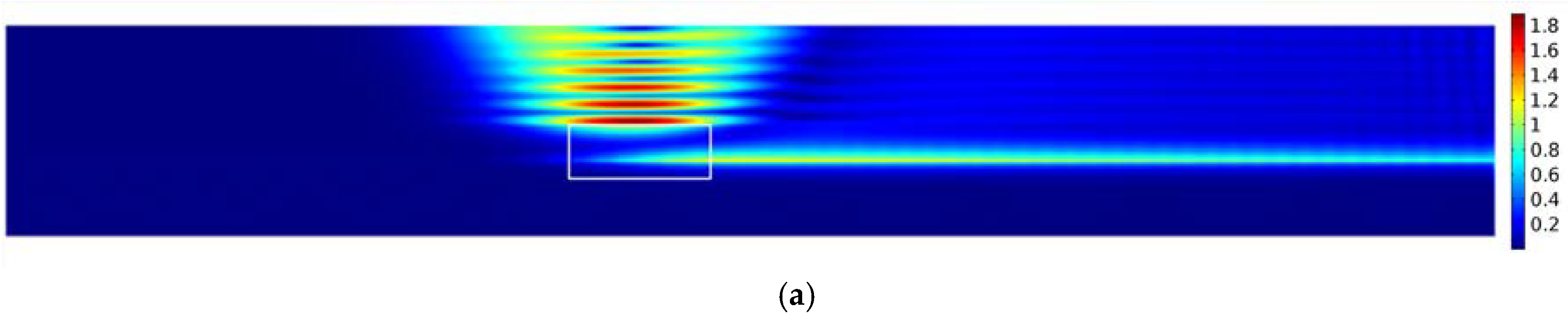
Figure 5. As a contrast, 
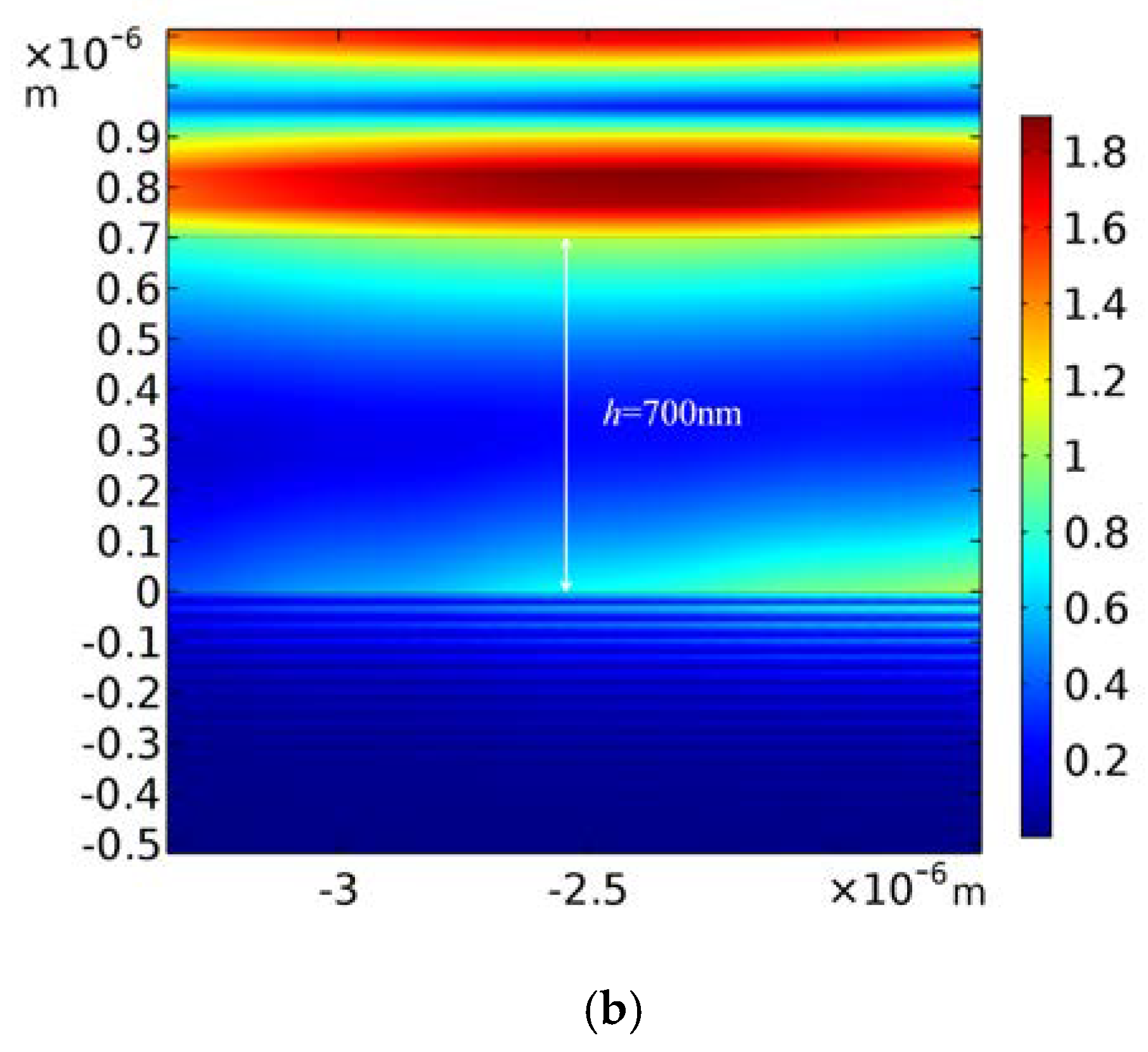
Figure 8a displays the forward SW with the propagation constant and related frequency acquired at Point C of the dispersion curve in Figure 4a. In this case, the light beam of the SW and the incident beam are on different sides of the normal, indicating that the propagation direction of the energy flow is in the same direction with the wave vector component of the SW along the x axis. Furthermore, in the light of the magnification of the white rectangle (see Figure 8a) depicted in Figure 8b, the field is mainly distributed in the partner dielectric medium; thus, the energy flow in the partner dielectric medium is dominant under this circumstance.

5. Conclusions

In summary, TM-polarized backward SWs implemented by a conventional homogenous dielectric medium in contact with an MMDM is theoretically demonstrated. By deploying the transfer-matrix method, backward SWs of anomalous dispersions have been proved to be closely related to the optical nonlocality caused by surface plasmon modes of the MMDM with an upper dielectric layer being adjacent to the partner dielectric medium, and appear only when the energy flow in the metallic layers is dominant. Owing to the optical nonlocality, the dispersion relations of the backward SWs are highly dependent on the periodicity of the MMDM that the frequency range of the backward SWs can be engineered by varying the unit-cell thickness or the filling factor. Moreover, based on the prism-coupled configuration, the light beam of the backward SW locates on the same side of the normal with the incident beam. A sharp contrast is thus displayed when comparing to the forward SW, in which the corresponding light beam and the incident beam are located at the different sides of the normal. By means of thin layer electrodeposition technology, such as the electrochemical atomic layer epitaxy method [40], this phenomenon may contribute to the ultimate goal of complete control of spatially propagating waves and SWs.

Author Contributions

Z.Z. conducted part of simulation and drafted the manuscript. X.Z. putted forward the idea of this paper. J.X. conducted part of simulation. Y.S. and Y.W. conducted theoretical analysis of formula and numerical results.

Funding

This research was funded by National Natural Science Foundation of China grant No. 11474078 and No. 11374079.

Acknowledgments

Z.Z. wishes to thank Zhongquan Nie and Xingzhi Wu for the help in formatting the manuscript.

Conflicts of Interest

The authors declare no conflicts of interest.

References

  1. Barnes, W.L.; Dereux, A.; Ebbesen, T.W. Surface plasmon subwavelength optics. Nature 2003, 424, 824–830. [Google Scholar] [CrossRef] [PubMed]
  2. Zayats, A.V.; Smolyaninov, I.I. Near-field photonics: surface plasmon polaritons and localized surface plasmons. J. Opt. A Pure Appl. Opt. 2003, 5, 303–436. [Google Scholar] [CrossRef]
  3. Jorgenson, R.C.; Yee, S.S. A fiber-optic chemical sensor based on surface plasmon resonance. Sens. Actuators B Chem. 1993, 12, 213–220. [Google Scholar] [CrossRef]
  4. Schultz, D.A. Plasmon resonant particles for biological detection. Curr. Opin. Biotechnol. 2003, 14, 13–22. [Google Scholar] [CrossRef]
  5. Ditlbacher, H.; Krenn, J.R.; Schider, G.; Leitner, A.; Aussenegg, F.R. Two-dimensional optics with surface plasmon polaritons. Two-Dimens. Opt. Surf. Plasmon. Polaritons. 2002, 81, 1762. [Google Scholar] [CrossRef]
  6. Righini, M.; Zelenina, A.S.; Girard, C.; Quidant, R. Parallel and selective trapping in a patterned plasmonic landscape. Nat. Phys. 2007, 3, 477–480. [Google Scholar] [CrossRef]
  7. Specht, M.; Pedarnig, J.D.; Heckl, W.M.; Hänsch, T.W. Scanning plasmon near-field microscope. Phys. Rev. Lett. 1992, 68, 476–479. [Google Scholar] [CrossRef] [PubMed]
  8. Sekhon, J.S.; Verma, S.S. Plasmonics: the future wave of communication. Curr. Sci. 2011, 101, 484–488. [Google Scholar]
  9. Gramotnev, D.K.; Bozhevolnyi, S.I. Nanofocusing of electromagnetic radiation. Nat. Photon. 2014, 8, 13–22. [Google Scholar] [CrossRef]
  10. D’yakonov, M.I. New type of electromagnetic wave propagating at an interface. Sov. Phys. JETP 1988, 67, 714–716. [Google Scholar]
  11. Takayama, O.; Crasovan, C.; Johansen, S.K.; Mihalache, D.; Artigas, D.; Torner, L. Observation of Dyakonov Surface Waves. Phys. Rev. Lett. 2009, 102, 043903. [Google Scholar] [CrossRef] [PubMed]
  12. Yeh, P.; Yariv, A.; Hong, C.S. Electromagnetic propagation in periodic stratified media. I. General theory. J. Opt. Soc. Am. 1977, 67, 423–438. [Google Scholar] [CrossRef]
  13. Yeh, P.; Yariv, A.; Cho, A.Y. Optical surface waves in periodic layered media. Appl. Phys. Lett. 1978, 32, 104. [Google Scholar] [CrossRef]
  14. Maas, R.; Parsons, J.; Engheta, N.; Polman, A. Experimental realization of an epsilon-near-zero metamaterial at visible wavelengths. Nat. Photon. 2013, 7, 907–912. [Google Scholar] [CrossRef]
  15. Riley, C.T.; Smalley, J.S.; Post, K.W.; Basov, D.N.; Fainman, Y.; Wang, D.; Liu, Z.; Sirbuly, D.J. High-quality, ultraconformal aluminum-doped zinc oxide nanoplasmonic and hyperbolic metamaterials. Small 2016, 12, 892–901. [Google Scholar] [CrossRef] [PubMed]
  16. Sreekanth, K.V.; Alapan, Y.; ElKabbash, M.; Ilker, E.; Hinczewski, M.; Gurkan, U.A.; de Luca, A.; Strangi, G. Extreme sensitivity biosensing platform based on hyperbolic metamaterials. Nat. Mater. 2016, 15, 621–627. [Google Scholar] [CrossRef] [PubMed] [Green Version]
  17. Jacoba, Z.; Narimanov, E.E. Optical hyperspace for plasmons: Dyakonov states in metamaterials. Appl. Phys. Lett. 2008, 93, 221109. [Google Scholar] [CrossRef]
  18. Takayama, O.; Dmitriev, P.; Shkondin, E.; Yermakov, O.; Panah, M.; Golenitskii, K.; Jensen, F.; Bogdanov, A.; Lavrinenko, A. Experimental observation of Dyakonov plasmons in the mid-infrared. Semiconductors 2018, 52, 442–446. [Google Scholar] [CrossRef]
  19. Lakhtakia, A.; Polo, J.A., Jr. Dyakonov-Tamm wave at the planar interface of a chiral sculptured thin film and an isotropic dielectric material. J. Eur. Opt. Soc. 2007, 2, 07021. [Google Scholar] [CrossRef]
  20. Pulsifer, D.P.; Faryad, M.; Lakhtakia, A. Observation of the Dyakonov-Tamm Wave. Phys. Rev. Lett. 2013, 111, 243902. [Google Scholar] [CrossRef] [PubMed] [Green Version]
  21. Rahachou, A.I.; Zozoulenko, I.V. Waveguiding properties of surface states in photonic crystals. J. Opt. Soc. Am. B 2006, 23, 1679–1683. [Google Scholar] [CrossRef]
  22. Foteinopoulou, S.; Kafesaki, M.; Economou, E.N.; Soukoulis, C.M. Backward surface waves at photonic crystals. Phys. Rev. B 2007, 75, 245116. [Google Scholar] [CrossRef]
  23. Smirnova, D.; Buslaev, P.; Iorsh, I.; Shadrivov, I.V.; Belov, P.A.; Kivshar, Y.S. Deeply subwavelength electromagnetic Tamm states in graphene metamaterials. Phys. Rev. B 2014, 89, 245414. [Google Scholar] [CrossRef]
  24. Popov, V.; Lavrinenko, A.V.; Novitsky, A. Surface waves on multilayer hyperbolic metamaterials: Operator approach to effective medium approximation. Phys. Rev. B 2018, 97, 125428. [Google Scholar] [CrossRef] [Green Version]
  25. Tamm, I.E. On the possible bound states of electrons on a crystal surface. Phys. Z. Sov. Union 1932, 1, 733–735. [Google Scholar]
  26. Vinogradov, A.P.; Dorofeenko, A.V.; Merzlikin, A.M.; Lisyansky, A.A. Surface states in photonic crystals. Phys. Uspekhi 2010, 53, 243–256. [Google Scholar] [CrossRef]
  27. Namdar, A.; Shadrivov, I.V.; Kivshar, Y.S. Backward Tamm states in left-handed metamaterials. Appl. Phys. Lett. 2006, 89, 114104. [Google Scholar] [CrossRef] [Green Version]
  28. Iorsh, I.; Orlov, A.; Belov, P.; Kivshar, Y. Interface modes in nanostructured metal-dielectric metamaterials. Appl. Phys. Lett. 2011, 99, 151914. [Google Scholar] [CrossRef]
  29. Gric, T.; Hess, O. Tunable surface waves at the interface separating different graphene-dielectric composite hyperbolic metamaterials. Opt. Express 2017, 25, 11466. [Google Scholar] [CrossRef] [PubMed] [Green Version]
  30. Rytov, S.M. Electromagnetic properties of layered media. Sov. Phys. JETP 1956, 2, 466. [Google Scholar]
  31. Yariv, A.; Yeh, P. Electromagnetic propagation in periodic stratified media. II. birefringence, phase matching, and X-ray lasers. J. Opt. Soc. Am. 1977, 67, 438–448. [Google Scholar] [CrossRef]
  32. Krishnamoorthy, H.N.; Jacob, Z.; Narimanov, E.; Kretzschmar, I.; Menon, V.M. Topological transitions in metamaterials. Science 2012, 336, 205–209. [Google Scholar] [CrossRef] [PubMed]
  33. Kidwai, O.; Zhukovsky, S.V.; Sipe, J. Effective-medium approach to planar multilayer hyperbolic metamaterials: Strengths and limitations. Phys. Rev. A 2012, 85, 053842. [Google Scholar] [CrossRef]
  34. Cortes, C.; Newman, W.; Molesky, S.; Jacob, Z. Quantum nanophotonics using hyperbolic metamaterials. J. Opt. 2012, 14, 063001. [Google Scholar] [CrossRef]
  35. Orlov, A.A.; Voroshilov, P.M.; Belov, P.A.; Kivshar, Y.S. Engineered optical nonlocality in nanostructured metamaterials. Phys. Rev. B 2011, 84, 045424. [Google Scholar] [CrossRef] [Green Version]
  36. Elser, J.; Podolskiy, V.A.; Salakhutdinov, I.; Avrutsky, I. Nonlocal effects in effective-medium response of nanolayered metamaterials. Appl. Phys. Lett. 2007, 90, 191109. [Google Scholar] [CrossRef] [Green Version]
  37. Jacob, Z.; Smolyaninov, I.I.; Narimanov, E.E. Broadband Purcell effect: radiative decay engineering with metamaterials. Appl. Phys. Lett. 2012, 100, 181105. [Google Scholar] [CrossRef]
  38. Chilwell, J.; Hodgkinson, I. Thin-films field-transfer matrix theory of planar multilayer waveguides and reflection from prism-loaded waveguides. J. Opt. Soc. Am. A 1984, 7, 742–753. [Google Scholar] [CrossRef]
  39. Orlov, A.; Iorsh, I.; Belov, P.; Kivshar, Y. Complex band structure of nanostructured metal-dielectric metamaterials. Opt. Express 2013, 21, 1593–1598. [Google Scholar] [CrossRef] [PubMed]
  40. Fernandes, V.C.; Salvietti, E.; Loglio, F.; Lastraioli, E.; Innocenti, M.; Mascaro, L.H.; Foresti, M.L. Electrodeposition of PbS multilayers on Ag(111) by ECALE. J. Appl. Electrochem. 2009, 39, 2191. [Google Scholar] [CrossRef]
Figure 1. The geometry of a MMDM in contact with a homogenous dielectric medium. MMDM: the multilayered metal–dielectric metamaterial.
Applsci 08 01420 g001
Figure 2. Dispersion relations and corresponding group velocities of the TM-polarized surface states supported by a homogenous dielectric medium and an MMDM with the filling factor being set as f = 0.7 in the UDL case. Relative permittivities ε i = 1 and ε d = 18.8 , refer to the partner dielectric medium (air) and dielectric layers (PbS), respectively. (a) Dispersion relations with different unit-cell thicknesses. (b) Group velocities with different unit-cell thicknesses. (c) The frequency range and the relevant upper and lower threshold frequencies of the anomalous dispersions as a function of the unit-cell thickness.
Applsci 08 01420 g002
Figure 3. Dispersion relations and corresponding group velocities of the TM-polarized surface states supported by a homogenous dielectric medium and an MMDM with the unit-cell thickness being set as L = 0.3 λ p in UDL case. The material parameters are set as the same values as those in Figure 2. (a) Dispersion relations with different filling factors. (b) Group velocities with different filling factors. (c) The frequency range and the relevant upper and lower threshold frequencies of the anomalous dispersions as a function of the filling factor.
Applsci 08 01420 g003
Figure 4. Dispersion relations of the TM-polarized surface states supported by a homogenous dielectric medium and an MMDM in the UML case. The values of material parameters are the same as those in Figure 2. (a) Dispersion relations with different unit-cell thicknesses when the filling factor is set as f = 0.7 . (b) Dispersion relations with different filling factors when the unit-cell thickness is set as L = 0.3 λ p .
Applsci 08 01420 g004
Figure 5. The profiles of the tangential components of the magnetic field and the time-averaged Poynting vector of TM-polarized surface states with (a,b) f = 0.7 , L = 0.1 λ p , Ω = 0.299 and β = 2.392 × 10 7 m 1 in the UDL case, (c,d) f = 0.7 , L = 0.1 λ p , Ω = 0.2452 and β = 0.5613 × 10 7 m 1 in UDL case, (e,f) f = 0.7 , L = 0.1 λ p , Ω = 0.2942 and β = 0.6628 × 10 7 m 1 in the UML case. The yellow regions represent the metallic layers while the green regions represent the dielectric layers. The white regions on the left side of figures denote the partner dielectric medium.
Applsci 08 01420 g005
Figure 6. Sketch of a forward or backward SW excited by a TM-polarized Gauss beam based on a prism-coupled configuration. The beam waist G w = 2000   nm and the incident angle θ = arcsin ( β n p k 0 ) , where n p is the refraction index of the prism, and the thickness of the partner medium is h . The blue arrow represents the direction of energy flow of the backward SW while the green arrow represents the direction of energy flow of the forward SW. SW: surface wave.
Applsci 08 01420 g006
Figure 7. Backward SWs in the UDL case with parameters f = 0.7 , L = 0.1 λ p , Ω = 0.299 , β = 2.392 × 10 7 m 1 , h = 100   nm and n p = 6 (a) Distribution of the magnetic field of the whole calculation area. (b) Magnification of the white rectangle in (a). The region between the two dashed lines is the partner medium. The color bar represents the magnitude of the magnetic field.
Applsci 08 01420 g007
Figure 8. Forward SW in the UML case with f = 0.7 , L = 0.1 λ p , Ω = 0.2942 , β = 0.6628 × 10 7 m 1 , h = 700   nm and n p = 2 . (a) Distribution of the magnetic field of the whole calculation area. (b) Magnification of the white rectangle in (a). The region between the two dashed lines is the partner medium.
Applsci 08 01420 g008aApplsci 08 01420 g008b

