Article

Design and Multi-Objective Optimization of Fiber-Reinforced Polymer Composite Flywheel Rotors

by
Marvin Mittelstedt
1,
Christian Hansen
1 and
Pierre Mertiny
2,*
1
Institute of Mechatronic Systems, Leibniz University of Hanover, Appelstraße 11a, 30167 Hanover, Germany
2
Department of Mechanical Engineering, University of Alberta, 10-203 Donadeo Innovation Centre for Engineering, 9211-116 Street NW, Edmonton, AB T6G 1H9, Canada
*
Author to whom correspondence should be addressed.
Appl. Sci. 2018, 8(8), 1256; https://doi.org/10.3390/app8081256
Submission received: 23 June 2018 / Revised: 23 July 2018 / Accepted: 24 July 2018 / Published: 30 July 2018
(This article belongs to the Section Mechanical Engineering)

Abstract

:
A multi-objective optimization strategy to find optimal designs of composite multi-rim flywheel rotors is presented. Flywheel energy storage systems have been expanding into applications such as rail and automotive transportation, where the construction volume is limited. Common flywheel rotor optimization approaches for these applications are single-objective, aiming to increase the stored energy or stored energy density. The proposed multi-objective optimization offers more information for decision-makers optimizing three objectives separately: stored energy, cost and productivity. A novel approach to model the manufacturing of multi-rim composite rotors facilitates the consideration of manufacturing cost and time within the optimization. An analytical stress calculation for multi-rim rotors is used, which also takes interference fits and residual stresses into account. Constrained by a failure prediction based on the Maximum Strength, Maximum Strain and Tsai-Wu criterion, the discrete and nonlinear optimization was solved. A hybrid optimization strategy is presented that combines a genetic algorithm with a local improvement executed by a sequential quadratic program. The problem was solved for two rotor geometries used for light rail transit applications showing similar design results as in industry.

1. Introduction

Leading countries in renewable energy such as Sweden or Germany rely on energy storage systems. Sun and wind are fluctuating sources of energy and cannot provide the required energy at any time. Therefore, the probability of power failures increases, resulting in significant costs. In Berlin, the outage cost per hour at noon is estimated at 22.74 million euro [1]. When more electricity is produced by renewable energy sources than dissipated, energy storage systems store the energy and allow consuming the electricity later. In addition, energy storage systems help harness the potential of recuperation in transportation applications [2,3], e.g., in automobiles or light rail transit (LRT) trains.
There are several ways to store energy. While batteries are the most popular approach, they have certain disadvantages—such as limited cycle life and disposal issues—making them unsuitable for some applications [4]. Flywheel Energy Storage Systems (FESS) are an interesting alternative, suitable for short-term storage with high cycle efficiency >85% [4,5]. Essentially, FESS typically consist of a rotor for storing energy, a bearing system to support the rotor, a motor/generator unit (electrical machine) for converting the mechanical energy into electrical energy and vice versa, and an enclosure that also functions as vacuum housing to minimize air drag losses on the fast spinning rotor [6].
FESS allow a very high number of charge/discharge cycles resulting in a useful lifetime of greater than 20 years. Further, FESS have a low environmental impact and the state of charge can be easily monitored. FESS excel in uninterruptible power supply (UPS) applications and electrical grid frequency regulation due to their high reliability, fast response and high-cycle charge-discharge capabilities [5,7]. On the other hand, less experience with this technology and higher costs currently impede the application of FESS in other fields [8]. Finding a cost-efficient design for FESS is therefore crucial to make them more attractive to a wider range of applications.
The flywheel rotor is the determining factor for the energy capacity as well as the typically most cost-intensive component. Dimensions and material choices for FESS rotors vary significantly depending on the application. Small rotors made of lightweight materials such as fiber-reinforced polymer composites having a mass in the order of a few tens kilograms can typically be found in mobility applications such as hybrid and electric vehicles, including energy recovery systems for some race cars. On the upper end, steel FESS rotors with mass in the order of tens of metric tons exist as stationary systems for the short-term energy supply for very high peak-power applications [7]. Flywheel rotors for various applications have been modeled and optimized in previous works [9,10,11,12,13,14]. Considering fiber-reinforced polymer composite rotors, optimization models were restricted by circumferential stresses and radial stresses in the rotor. To determine whether the rotor will fail, failure criteria—such as the Maximum Strength, Maximum Strain or the Tsai-Wu criterion—were introduced. To increase the energy density of the flywheel, multi-rim rotors are often considered. Since the circumferential stresses are at their highest level at the outermost rim, it would be useful to employ high strength materials such as unidirectional carbon fiber polymer composites that are filament-wound to form the outer rim geometry. For the inner rims lower strength materials with lower cost are usually sufficient, such as glass or aramid fiber composites, because stresses are comparatively low. Please note that rims may also be made of isotropic materials such as metals. Therefore, cost efficiency will increase as expensive materials are not employed in each rim. Further, flywheel rotors may also fail due to radial stresses since these act transverse to circumferentially oriented fibers. Assembling the rims into a rotor via press fit improves the stress distribution due to residual compressive radial stresses [15]. One of the first analytical methods to calculate the rotor stresses was published in [9]. This model also considered interference between adjacent rims caused by press fits. The model was later supplemented by the consideration of residual stresses due to the curing process [10,14], and a split-type hub [16]. Besides the analytical methods, there are also numerical methods to calculate the stresses [12,13]. Numerical models using the finite element method can determine results with greater accuracy especially for complex geometries. However, these methods cause higher computation time, which is a significant disadvantage for optimization problems. Irrespective of the modeling approach, the design space for multi-rim rotors is significant and the challenge for optimization strategies is not only finding optimal design parameters, such as the number of rims, the rim thicknesses, the size of interference fits and the material selection, but also providing guidance to the designer by elucidating suitable designs within the design space.

1.1. State of the Art

To this point, previous rotor optimization approaches, discussed in the technical literature, focus on single objective problems and typically optimize the stored energy density (SED) or the energy to material cost ratio. In [12] an optimization approach is presented that optimizes the cost to energy ratio based only on material costs. Since flywheel rotors are scalable, finding the solution with the highest energy to cost ratio is sufficient to create each cost- and energy combination required. However, FESS technology is also expanding into applications where the construction volume is limited, such as rail and automotive transportation. Scaling of cost to energy ratio-optimized designs is therefore not possible and the ability to choose between different optimal designs on a Pareto-front becomes more useful. Furthermore, the manufacturing process has not been modeled in previous studies and therefore manufacturing time and cost have been neglected. Also, the material selection and the number of rims were externally given, therefore the optimization in [12,13] was limited to optimal rim thicknesses.

1.2. Outline of the Current Study

In this study, a hybrid multi-objective optimization algorithm is presented. Since the material selection is also considered, the optimization problem is discrete. Gradient-based optimization techniques are not feasible for discrete optimization, therefore a genetic algorithm (GA) supported by a local improvement was used. Global optimization techniques such as the GA generally converge slower than gradient-based algorithms. However, evolutionary algorithms, such as the GA, are able, due to their working procedure, to find several Pareto-solutions in a single iteration. Also, they are robust and require only limited knowledge about the problem [17,18]. The local improvement, which is executed by sequential quadratic programming (SQP), solves a continuous sub-problem based on initial solutions created by the GA. The basic idea of using a local improvement strategy to improve the solution of an optimization is also presented in [19]. SQP is a local gradient-based optimization algorithm for single-objective nonlinear optimization problems with nonlinear equality and inequality constraints [20]. The proposed algorithm optimizes three objectives: energy capacity, costs and productivity. The algorithm therefore considers the influence of manufacturing through a novel modeling approach. This approach provides a better understanding of trade-offs between different design solutions. Employing multi-objective optimization may yield more practicable information for decision-makers to select the right design for a specific flywheel application. To create safe designs, each of the above-mentioned failure criteria was evaluated, i.e., Maximum Strength, Maximum Strain and the Tsai-Wu criterion. The algorithm was used to solve optimization problems for cylindrical disk-shaped geometries commonly used in mobility applications such as LRT.

2. Manufacturing Process

The manufacturing process of multi-rim composite rotors can be categorized into four process steps: filament winding of the rotor rims, curing, machining (turning) of the rim to provide toleranced surfaces for assembly, and finally press fitting. Please note that rotor rim assembly via press fitting is not mandatory. Alternatively, pre-stressed fibers may be wound onto a rotor hub. Nevertheless, to tailor the model to the assembly methods used in the case studies considered as part of this article, press fitting was included in the present investigation. A schematic of the entire process is shown in Figure 1.

2.1. Filament Winding Process

The wet filament winding process typically requires four different devices: the fiber tensioner, the resin mixing system, the resin bath, and the filament winding machine. These devices are linked and may operate simultaneously. Fibers such as glass, carbon or aramid are stored on creels which are located in the fiber tensioner. Each rim will be wrapped around a mandrel situated on the filament winding machine. To prepare the winding process, the mandrel has to be cleaned and pretreated with a release agent. Further, the tensioner must be stocked with fiber creels, and the resin and the curing agent are blended together in a specific ratio. The resin bath must be preheated to a specific temperature to ensure proper resin viscosity. During the winding process, the electric drive in the winding machine keeps the fibers in motion. The motor is set at a suitable rotational speed. Often the rotational speed is constant, causing the fiber speed to increase as the rim becomes larger. This must be considered when winding a large flywheel. In such cases, it may be necessary to adjust the rotational speed during the process, as otherwise the fiber speed may exceed allowable limits for achieving a quality product, e.g., due to insufficient fiber wetting in the resin bath. Before the fibers reach the mandrel, they dip through the resin bath filled with a mixture of resin and curing agent. The fiber tensioner applies tension to the fibers while they are wound onto the mandrel, ensuring proper part consolidation. After winding, all manufacturing components that are exposed to resin are cleaned in a solvent bath [21].

2.2. Curing Process

After completion of the winding process, the entire mandrel-rim assembly is placed into the curing oven. Some curing ovens can accommodate more than one mandrel. During the curing process inside the oven, mandrels are typically rotated at low speeds (10–15 rpm) with their axes aligned horizontally to promote part roundness and even resin distribution, which may otherwise be compromised due to the effect of gravity. The oven is operated at an appropriate temperature that ensures adequate curing (cross-linking) of the polymer matrix [21]. For flywheel rim fabrication epoxy polymer matrices are commonly used, which, depending on the epoxy system, have target curing temperatures ranging from room temperature to about 150 °C. As a general rule, higher temperatures may lead to higher residual stresses in the composite materials, which may cause damage upon cooling of the rims or weaken the flywheel during operation. Lower oven temperatures, on the other hand, increase the curing time and hence cause increasing costs and decreasing productivity. For that reason a limit is imposed on the number of rims that can be processed with a curing oven.

2.3. Turning Process and Interference Fits

To prepare the rims for interference fit assembly, the outer diameter and possibly the surface on the inside of each rim need to be machined. The machining step is necessary to ensure the correct dimensions and tolerances and smooth surfaces required for interference fit assembly. Further improvement of the surface finish is possible by sanding. Machining is typically employed utilizing a lathe.
As described above, multi-rim rotors increase the SED, among others, due to interference fits. Interference fits may be created by temperature fits or press fits or a combination of the two. The basic idea of temperature fits is that materials expand (or contract) when temperature changes. Composite materials often have a low coefficient of thermal expansion (CTE). In fact, unidirectional carbon and aramid fiber composites may even have a negative CTE in fiber direction. Hence, deformation must be sufficient to achieve adequate radial compression. However, a temperature fit is a good option to fit a metallic rim or hub into a composite rim. Alternatively, a press fit may be employed. In [15] two different methods for press fitting are presented. To facilitate press fit assembly, certain rim geometries may be incorporated, see Figure 2. The first method uses tapered surfaces of the rims. The second method employs a tapered guiding tool in front of the inner rim to expand the outer rim during the process. By using tapered shapes the vertical forces, required to fit the inner rim into the outer rim, can be reduced.

2.4. Machine Costs

A basic manufacturing system is herein considered. It consists of a single four-axis filament winding machine and a fiber tensioner that can be loaded with up to six creels [21]. Further, a resin bath, a resin mixing system, a lathe, a press, and a curing oven are part of the manufacturing system. The required space to calculate room costs along with estimated purchase prices are presented in Table 1.
In the optimization model, the machine costs are considered by calculating the machine hour rate (MHR). The total time a machine operates within one year is toperation. In accordance with [21], 252 days at 8 h per day are assumed, equaling 2016 h per year. KA are the cost-accounting depreciations. This study considers a linear depreciation over 10 years. After 10 years the machine is replaced by a newer version. KI are the cost-accounting interests which are not an actual expense but reflect the opportunity costs. These costs are not included in the presented study. KM are the maintenance costs which are assumed to be 5% of the acquisition price per year. KR and KE are room costs and energy costs, respectively. Energy costs are neglected in this study and the room costs are assumed to be 20 CAD/m2. An example calculation of the MHR for the four-axis filament winding system consisting of a four-axis filament winding machine, a resin mixing system, a resin bath and a fiber tensioner equipped with six creels is shown in Table 2. Similarly, the MHR of the oven, the lathe and the press are calculated. The MHRs of all machines are depicted in Table 3. Please note that MHR are facility and enterprise dependent, and values used in this study should therefore be considered an example.

3. Modeling

The modeling of the total stored energy (TSE) and material costs is based on [12] while the analytical calculation of stresses primary rests on [9,10]. To the author’s knowledge, the consideration of the productivity and manufacturing costs is a novel approach not presented in the technical literature before.

3.1. Total Stored Energy

The rotor stores kinetic energy by rotation. Assuming a mere rotation around its axis of symmetry, z, with the rotational velocity ω and the moment of inertia Izz, the energy can be expressed as
E kin = 1 2 I zz ω 2
The moment of inertia is defined by
I zz = 1 2 j = 1 N rim m j ( r j + 1 2 + r j 2 ) ,
where mj is the mass of each rotor rim and rj and rj+1 are the inner and outer rim radius, respectively. Given the material density ρj, the rim mass can be expressed as
m j = π h ρ j ( r j + 1 2 r j 2 ) .

3.2. Costs

3.2.1. Material Costs

Since the material costs are only depended on the mass and the price per mass cmaterial,j the calculation is straightforward, i.e.,
C material = π h j = 1 N rim ρ j c material , j ( r j + 1 2 r j 2 ) .

3.2.2. Manufacturing Costs

In general, manufacturing costs are subdivided into operating costs and conversion costs. Operating costs occur during the operation of the machine. Hence, they are determined by the process time multiplied by the sum of the MHR and the labor costs. Conversion costs are incurred through cleaning, replacing of tools or other processes necessary to prepare a machine for the next task. Conversion costs are calculated by multiplying the conversion time by the sum of the MHR and the conversion costs per time cconv. The MHR is part of the calculation for conversion costs because the machine cannot be used for other tasks during conversion. cconv may represent labor cost or another MHR when a robot performs the conversion. Since a conversion generally happens for each rim, the conversion costs are multiplied by the number of rims Nrim. Equation (5) shows a generic formula for the manufacturing costs.
C manu , generic = t process ( M H R + c labor ) + N rim t conv ( M H R + c conv ) .
The required time for the filament winding process is determined by the volume of the rim, the cross-sectional area of a fiber strand and the speed of the fibers. It should be noted that the speed of the fibers is not directly configured but the rotational speed of the mandrel. As the rim grows larger during the winding process, the fiber speed also increases. For the calculation of the process time it is sufficient to calculate the average fiber speed. The filament winding process time can be written as follows
t winding = j = 1 N rim π h ( r j + 1 2 r j 2 ) N creels v fibers A roving .
The labor cost is assumed to be 35 CAD/h. According to [21], the conversion time for the preliminary work and the cleaning process for a four-axis filament winding machine is 80 min. Finally, the costs for filament winding must be divided by the number of spindles for mandrel rotation and the number of filament winding machines, respectively.
The curing time is depended on many factors such as the oven power, the rim temperature caused by the chemical reaction of the resin systems and the heat capacity of the rims. These factors are rather complex, and hence, the curing time is considered a design variable. Since an oven may be able to cure several rims at the same time, the manufacturing costs per rotor must be divided by the oven capacity. On the other hand, rotors may consist of more than one rim. Hence the manufacturing costs must be multiplied by the rim number. Thus, the cost of curing can be written as
C curing = ( t curing ( M H R oven + c labor ) + t conv , curing ( M H R + c conv , curing ) ) N rim C oven .
According to [21], the conversion time for the oven is 25 min.
In the present study, only press fitting by tapered rim surfaces was considered. To create tapered surfaces between adjacent rims, the rims must be machined. The first rim does not need a tapered surface, whereas the following rims need a tapered surface only on the outside diameter (mandrels are provided with the appropriate geometry to shape the rim surface on the inside diameter). Assuming a constant speed of the tool vturning with the tool width dtool, the process time can be expressed as
t turning = j = 2 N r i m 4 π h r j v turning × d tool
The process costs result in
C turning = t turing ( M H R + c labor ) + N rim t conv , turning ( M H R + c conv , turning ) N machines
The conversion time for the press is assumed to be 10 min.
Similar to the curing time, the time for press fit assembly is also considered a design variable. According to [21], this time and the conversion time are 15 min each. Contrary to the previous manufacturing steps, the process requires two employees. Therefore, the price of labor is doubled. The process costs can be written as
C pressing = ( t pressing ( M H R + c labor ) + t conv , pressing ( M H R + c conv , pressing ) ) N rim N machines
Further details on the applied machine data can be found in Table 4.

3.3. Productivity

The fabrication of a multi-rim rotor not only induces higher TSEs and higher costs but also lowers productivity. Each rim is wound separately, thus causing additional manufacturing time for each process. The overall machine utilization for producing a flywheel is significantly increased. For companies engaged in series production with manufacturing systems that cannot be retooled in the short term, it is important to be able to meet demand. Productivity hence constitutes an important objective for flywheel rotor designs. This section describes the model approach for calculating productivity. In general, productivity is defined by the output per time.

3.3.1. Output

For the manufacturing process of the flywheel rotor, a machine shop production is assumed, allowing all processes to be executed in parallel. In this case, the output is only determined by the most time-consuming process. The process time is considered to be the time that is necessary to process the j-th rim. In practice, the most time-consuming processes are the curing and the winding process, respectively. Since the curing time for this study is approximately 7 h, the winding time for a single rim will usually be lower. Hence, it is assumed that curing is the most time-consuming process and will thus determine the output of the flywheel production. For this reason, the output is defined as
output = C oven / N rim .

3.3.2. Time

The total manufacturing time is the time required to produce the above-mentioned output. Unlike the process time, where only the time to produce a single rim is considered, the manufacturing time takes into account the number of rims that corresponds to the oven capacity Coven. The manufacturing times for each process can be written as follows:
t winding , total = ( t winding N rim + t conv , winding ) C oven / N machines t curing , total = t curing + t conv , curing t turning , total = ( t turning N rim + t conv , turning ) C oven / N machines t pressing , total = ( t pressing N rim + t conv , pressing ) C oven / N machines
The expression t winding N rim can be interpreted as the average operation time needed for a single rim. Eventually, the overall manufacturing time is calculated by determining the maximum
t manu = max ( t winding , total , t curing , total , t turning , total , t pressing , total ) .
Since one process may be repeated several times to produce one complete rotor, it should be noted that the most time-consuming process is not necessarily the process determining the overall manufacturing time. However, the process with the highest manufacturing time does not define the output. To gain a better understanding of this aspect, consider the following example.
The average winding process time is 3 h and the oven capacity is three rims. The curing time is assumed to be 7 h. Therefore, curing is the most time-consuming process. First, it is assumed that the most time-consuming process, curing, defines the output. Since the oven capacity is three rims and assuming three rims are needed to build a single flywheel, the output is one (see Equation (11)). The manufacturing time is then determined by the winding process, as 9 h are required to wind three rims, resulting in a productivity of 1/9 flywheels/hour. During this process, the curing oven is not used for 2 h, since the entire winding process takes longer than curing. Therefore, it is examined if the results are better when the winding process determines the output. Instead of winding three rims in a row, only two rims are wound. The output is then 2/3 flywheels. This time, the curing oven defines the total manufacturing time as the 7-h curing process takes longer than 6 h of winding. Thus, the productivity is 2/21 flywheels/h, which is lower than the previous productivity. Although the oven has no downtime during this process, it does not work to capacity, resulting in lower performance of the second approach. In general, a manufacturing process is always optimal if accepted that the most time-consuming process defines the output.

3.4. Analytical Stress Calculation and Failure Prediction

3.4.1. Load Cases

Rotor stresses are induced by rotation, temperature differences and press fits. During operation all of these effects together determine the total stress state in the rotor. Note that examining only the load case for operation is not sufficient. Therefore, as proposed in [13], three load cases are considered separately.
The first load case represents residual stresses due to the curing process. Residual stresses can have a significant impact on the maximum allowable speed and are therefore not negligible. The larger the temperature difference between curing and operation the higher these stresses will be. Residual stresses also become increasingly critical for a rising ratio of the outer to inner rim radius. Rims that are thinner in radial direction are therefore preferable in order to lower the effect of residual stresses.
The second load case considers stresses caused during press fit assembly. A press fit causes radial compressive stresses which counteract tensile stresses induced at high rotational speeds. This is generally a positive effect. By only determining the stresses during operation; however, it is not considered that rims can fail due to too high compressive stresses through the assembly process.
Finally, the third load case describes the rotor stresses during operation.

3.4.2. Analytical Stress Calculation

An analytical stress analysis which also considers interference and residual stresses can be found in previous publications [9,14] and is therefore only summarized. Introducing the radial and circumferential stresses σr and σθ, respectively, the following equation can be written
σ rr r + σ rr σ θ θ r + ρ r ω 2 = 0 .
The stress-strain-temperature relation is defined as
σ = Q ( ϵ α Δ T ) .
where Q is the stiffness matrix expressed in cylindrical coordinates, α is the thermal expansion coefficient vector, Δ T is the temperature change, ϵ and σ are the vector of strains and vector of stresses, respectively. The temperature change is based on the temperature difference between the stress-free curing temperature and the operating temperature. Hence, a higher curing temperature will lead to increased residual stresses. The stiffness matrix Q is defined by the material properties [22] and can be expressed as:
[ 1 E θ ν θ r E r ν θ z E z 1 E r ν rz E z sym . 1 E z ] 1 .
For flywheels with a low height to diameter aspect ratio, a plane stress state can be assumed. Therefore, the stresses σzz and σθz can be neglected. Each of the equations discussed in this subsection can be applied to any rim of the rotor. To calculate stresses and displacements for the entire rotor 2(Nrim − 1), continuity conditions are introduced. The radial stresses are continuous at the rim surfaces, while the radial displacements may differ by an interference δ(i) due to press fitting.
σ r i ( i + 1 ) = σ r o ( i ) ,
u r i ( i + 1 ) = u r o ( i ) + δ ( i ) ,
for i = 1 to Nrim − 1. The continuity of radial stresses is only valid as long as the rims are attached to each other. In case of interference fits the attachment vanishes when the tensile stresses induced by rotation exceed the radial stresses due to the interference fit. Hence, a computed tensile stress would lead to a detachment failure.
Since there are 2Nrim constraint equations and therefore 2Nrim unknown constants, two additional equations are required for the solution. They can be obtained by predefining the radial stresses at the innermost and outermost rotor radius.
σ r i ( 1 ) = p in ,   σ r o ( N rim ) = p out ,
with the inner and outer pressure pin and pout, respectively. In this study, pin and pout are set to zero.

3.4.3. Failure Criteria

To determine if the rotor will fail for aforementioned load cases, the computed stresses are compared to the material strengths. For this comparison, three mathematical failure criteria are considered in this study, i.e., Maximum Stress Failure Criterion, Maximum Strain Failure Criterion and Tsai-Wu Failure Criterion. The Maximum Stress Failure Criterion is defined as follows:
R 1 t = σ θ θ X T ,   for   σ θ θ 0 R 1 c = | σ θ θ | X C ,   for   σ θ θ < 0 R 3 t = σ rr Y T ,   for   σ rr 0 R 3 c = | σ rr | Y C ,   for   σ rr < 0 ,
where X T , X C , Y T , Y C , are the tensile and compressive material strengths of the longitudinal and transversal direction, respectively. R 1 t , R 1 c , R 3 t , and R 3 c denote the strength ratios which indicate failure if their value is greater than unity. For this reason, it is sufficient to calculate the maximum of the strength ratios R Stress = max ( R 1 t , R 1 c , R 3 t , R 3 c ) . Similarly, the Maximum Strain Ratio can be written as:
R 1 t = ϵ θ θ E 1 X T , for   ϵ θ θ 0 R 1 c = | ϵ θ θ | E 1 X C , for   ϵ θ θ < 0 R 2 t = ϵ zz E 2 Y T , for   ϵ zz 0 R 2 c = | ϵ z z | E 2 Y C , for   ϵ zz < 0 R 3 t = ϵ r r G 12 Y T , for   ϵ rr 0 R 3 c = | ϵ rr | G 12 Y C , for   ϵ rr < 0 .
Again, the strength ratio can be expressed by a single value
R Strain = max ( R 1 t , R 1 c , R 2 t , R 2 c , R 3 t , R 3 c ) .
The Tsai-Wu Failure Criterion is defined as [22]:
R T = F ¯ σ + ( F ¯ σ ) 2 + 4 ( σ T F ˜ σ ) 2
where F ¯ and F ˜ denote strength parameters defined by material properties, i.e.,
F ˜ = [ 1 X T X C 1 2 1 X T X C 1 Y T Y C 1 2 1 X T X C 1 Y T Y C 1 Y T Y C ] ,   F ¯ = [ 1 X T 1 X C 1 Y T 1 Y C ] .
None of these criteria is conservative. To develop an optimization algorithm which prefers the safest design, all criteria must be considered. Therefore, the maximum of these criteria is calculated:
R = max ( R Stress , R Strain , R T ) .

4. Optimization

4.1. Formulation and Characterization of the Optimization Problem

The goal of the rotor optimization is to find optimal rotor designs which yield a higher TSE, lower costs and a faster production. These conflicting objectives are considered separately, thus implying the need for multi-objective optimization. In addition to these objectives, there are also three constraints that represent the three load cases for which the rotor must be designed. To formulate the optimization problem, the optimization variables as well as the design variables are defined. Design variables are externally specified variables. This study primarily considers flywheels for transportation applications such as in cars or trains where the construction volume is limited. The height and the outer radius of the flywheel are therefore design variables. The inner radius depends on the hub and shaft geometry which is typically determined by the used electrical machine and bearing system.
FESS rotors are either built with an integrated or external electrical machine. While the external electrical machine uses a shaft, the integrated topology requires a central stator unit enclosed by the rotor. A major drawback of the external electrical machine is the necessary hub. High rotational velocities cause increasing radial forces in the rotor. Hence, the rotor will expand faster than the shaft. The hub must ensure a stable connection with the rim while compensating for the different growth of rim and shaft. The consequence is a considerable design challenge: if the hub is too rigid, it will detach under high radial stresses. Conversely, a too flexible hub does not allow transmitting the high forces from the rim to the shaft. An integrated topology avoids the aforementioned problems due to its different assembly. However, this advantage is associated with significant disadvantages. The air gap of (possible) magnetic bearings and of the electrical machine rises because of occurring strains with increasing rotational speed. Since an enlarged air gap requires increased magnetic flux to ensure the same power, energy efficiency is reduced. Further, the motor/generator is almost in direct contact with the composite materials. Due to the operation in a vacuum enclosure (to reduce substantial air drag losses), heat from electrical systems can only be dissipated by radiation. Thermal stresses on surrounding composite materials impose limitations because they reduce strength and may accelerate material creep processes. Since these disadvantages are difficult to overcome, the presented study is based on an external electrical machine configuration.
Based on the above consideration, the rotor inner radius is considered to be a design variable. The optimization tries to increase the TSE by designing a multi-rim rotor. The number of rims highly increases the optimization time. Therefore, a maximum number of rims Nrim,max is also externally specified limiting the computation time. Calculating production times and costs requires information about the used fabrication equipment. Related information represents the last design variable. Results of the presented optimization tool are therefore only optimal for the selected fabrication facility configuration. Even though this restricts the validity of the results to a specific configuration, this procedure also highly simplifies the optimization problem. In practice, companies usually have machines in place that cannot be easily replaced due to high acquisition costs, and hence, the optimization tool and design variables would have to be adjusted accordingly.
Optimization variables are optimized and returned by the algorithm. In this study, the optimization variables are the maximum angular velocity ωmax, the rim number Nrim as well as the rim thickness 
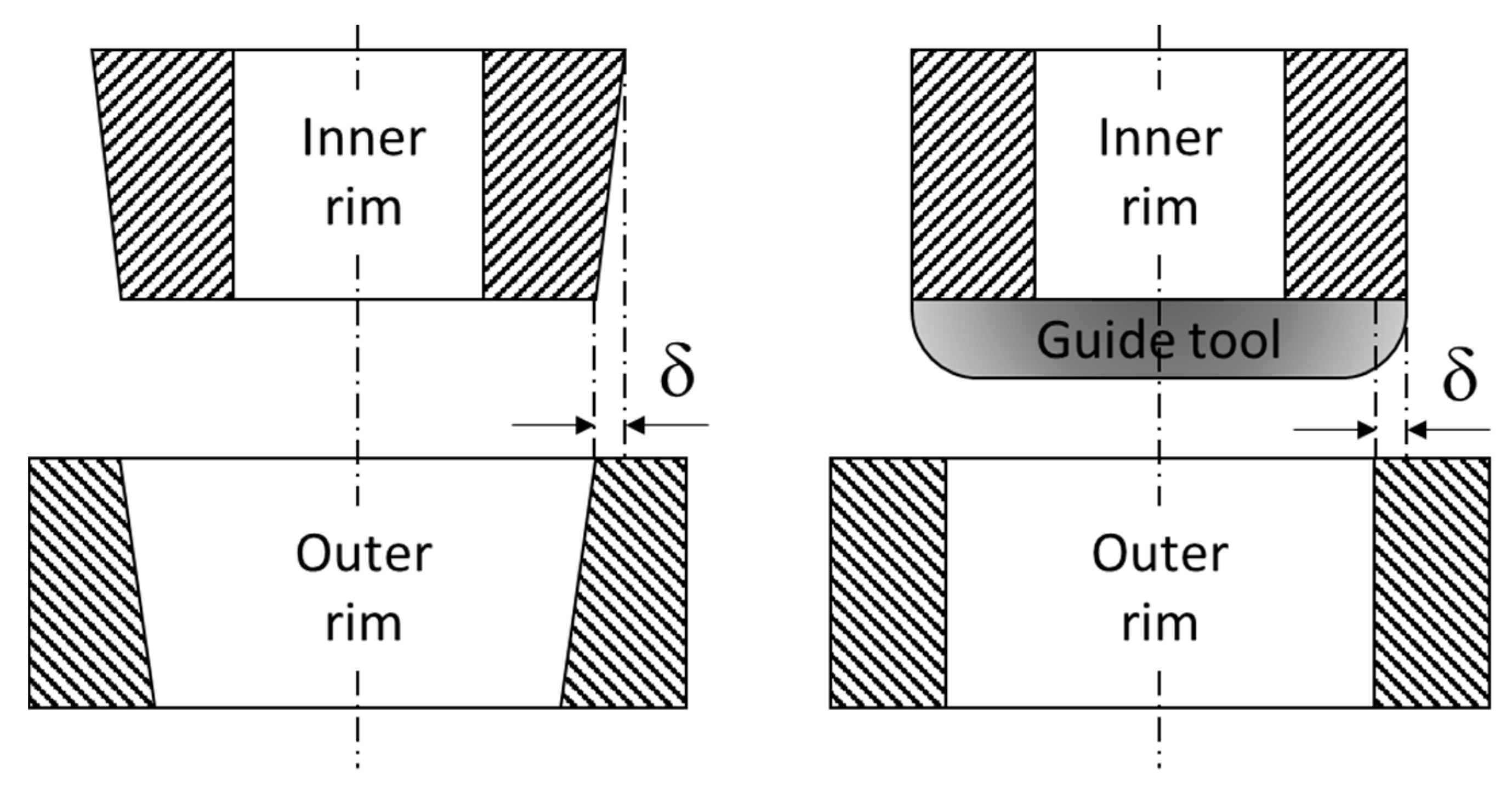
ti (i.e., the radial rotor dimension), the radial displacement due to press fitting δi and the material choice xmaterial,i for each rim i. The rim number and the material choice are the most challenging optimization variables as they tremendously increase the complexity of the optimization problem. The optimization of material properties is discrete. Since a gradient cannot be calculated for a discrete problem, this excludes all local optimization algorithms. Local optimization algorithms are more effective than global algorithms, therefore, the discretization of the problem negatively effects the computation time. To solve discrete optimization problems, they can be transferred into integer problems. For the considered problem, the material choice xmaterial,i has to be an integer variable:
x material , i .
Each integer represents a material of a given material set. Hence, x material , i can be interpreted as the material number. To specify the range of this variable, x material , i is bounded as:
1 x material , i < k ,
where k is the number of considered materials. To specify x material , i as taking discrete values from a set S = v 1 , , v k a function S ( x material , i ) is used that assigns a specific property to each material. Herein, S denotes a single material property, e.g., the material density ρ . Therefore, the function S ρ would return the density of material x material , i :
S ρ ( x material , i ) = ρ x material , i .
Since the material choice is the only integer variable in the optimization vector, the entire problem is called a mixed-integer optimization problem.
The number of optimization variables depends on the number of rims. For this reason, the addition of the rim number as an optimization variable leads to a dynamically sized optimization vector. There are no algorithms that can directly solve an optimization problem with a dynamically sized optimization vector. Therefore, the optimization problem must be solved for each number of rims separately. The mathematical formulation of the optimization problem is given by Equation (29).
Maximize   E kin ( x ) Minimize   C total ( x ) Maximize   P ( x ) with   respect   to   x = [ N rim ω t 1 t N rim x material , 1 x material , N rim δ 1 δ N rim ] subject   to   R residual ( x ) 1 0 , R pressfit ( x ) 1 0 , R operation ( x ) 1 0 , 1 x material , i k , x material , i , t 1 + + t N rim = r o r i , t 1 + + t N rim = r o r i , 0 δ i δ ub ,   and 0 ω ω ub ,
where R residual , R pressfit and R operation denote the strength ratios for the three load cases. The last three boundary conditions help to accelerate the convergence procedure by limiting the problem space. Herein t lb is the lower bound for the rim thickness which can be determined by the production accuracy. t ub , δ ub and ω ub are the upper bounds for the rim thickness, the radial displacement and the angular velocity, respectively. They are to be set to reasonable values. The sum of all rim thicknesses must be equal to the difference between outer and inner radius. This is the only equality constraint and further increases the problem complexity. In summary, the problem can be classified as a multi-objective, mixed-integer optimization problem with nonlinear equality and inequality constraints and a dynamically dimensioned optimization vector.

4.2. Hybrid Optimization Strategy

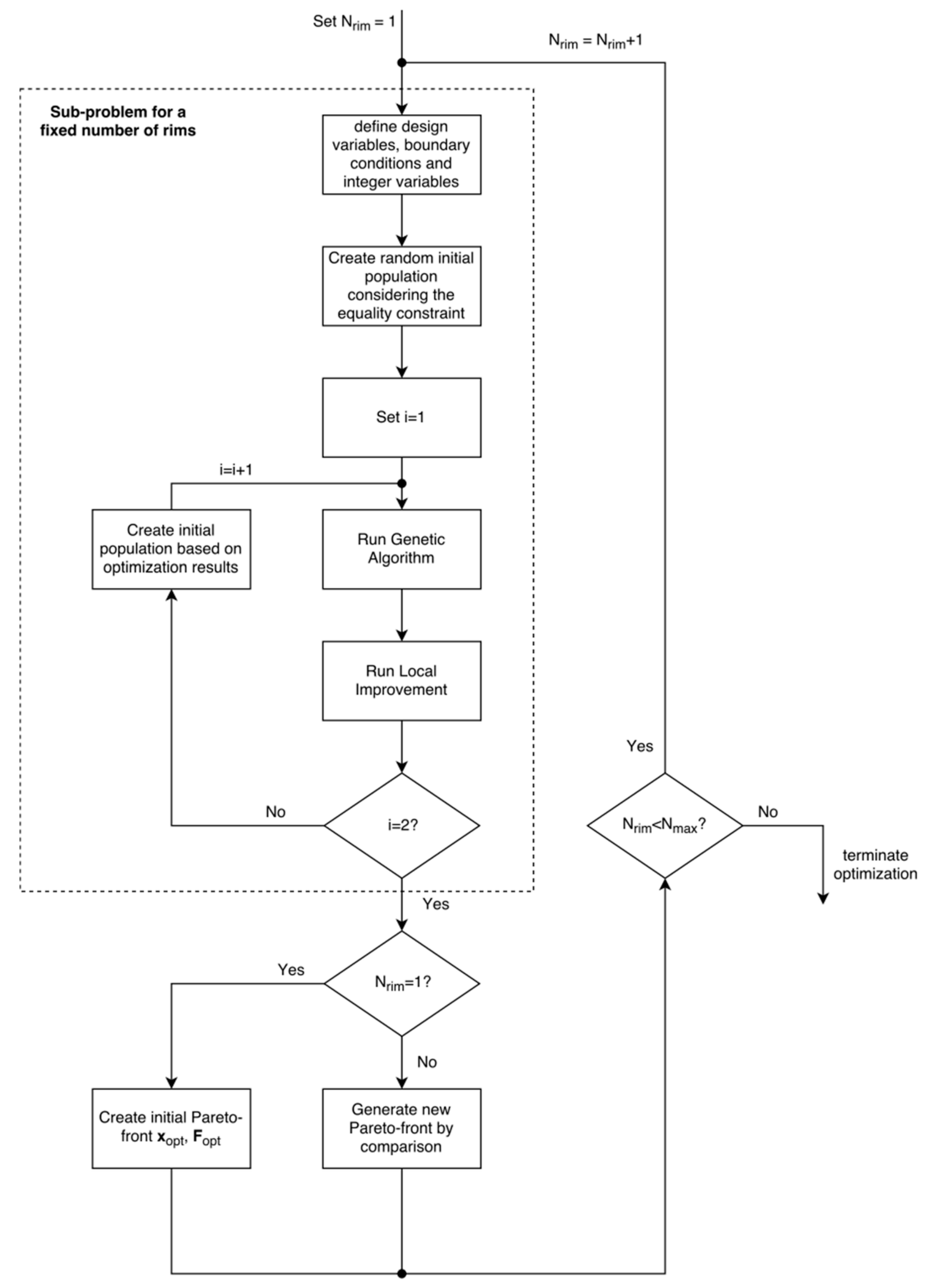
The optimization problem is solved by a hybrid optimization strategy. A schematic of the entire procedure is depicted in Figure 3. Since there is no algorithm to solve an optimization problem with a dynamically sized optimization vector, the problem is solved iteratively. Therefore, the algorithm runs separately for a pre-defined number of maximum rims Nmax. The number of rims considered is increased by one after each iteration. The optimization algorithm terminates if the maximum number of rims is reached. In the result, a sub-problem is created that considers the number of rims as a fixed design variable. Each iteration generates a Pareto-front with the optimization matrix Xopt and the corresponding objective values Fopt. Each solution xs,opt, fs,opt on this Pareto-front is compared to the previous Pareto-front to find the non-dominated solutions.
A solution Pareto-dominates another solution if the following equations are satisfied:
f j ( x 1 ) f j ( x 2 )   j   functions   in   f , f j ( x 1 ) < f j ( x 2 )   for   at   least   one   j .
Therefore, a Pareto-dominant solution has at least one objective value that is better and none that is worse than the objective values of the dominated solution.
For the sub-problem itself a combination of the GA and SQP was used, which were both implemented in the numerical computing environment MATLAB (MathWorks, Natick, MA, USA). The GA is not able to solve the sub-problem for Nrim > 1 in an appropriate time. The number of optimization variables is increased by three for each additional rim. The calculation of the fitness values takes longer with an increased number of rims. Further, a large number of optimization variables makes it more difficult for a stochastic optimization algorithm to find an optimal solution. To gain a better understanding of the problems associated with a GA, an example is analyzed.
A two-rim flywheel is considered, where the inner rim is made of a glass fiber composite ( x material = 1 ) and the outer rim is made of a carbon fiber composite ( x material = 2 ). In Table 5 three feasible solutions for the optimization vector and the corresponding objective values are shown. Solution one and solution two differ only in their rotational speed and the interference between the both rims. While the speed is increased, the interference is decreased, resulting in higher kinetic energy. Consequently, solution two has a greater strength ratio, thus the flywheel operates closer to its load limit. Since these variables do not affect the productivity or the cost, solution two Pareto-dominates solution one. Assuming the GA compares solution one with solution two, it would assign a better fitness value to solution two. Solution three is created by only increasing the rotational speed, resulting in the same objective values as solution two. The third solution; however, has lower stresses due to the greater interference. Therefore, the third solution would still be feasible even if the rotational speed is set higher. Overall, the third solution is the best choice. The GA prefers solution two over solution one. Without knowing solution three, the genetics of solution two would be used to derive the next generation. Therefore, the worse gene of the interference is also transferred to the descendants. This example highlights the fact that the GA considers only the fitness value and no gradients. The positive impact of the increased rotational speed overcompensates the negative impact of the decreased interference. The algorithm; however, only sees the result, which is the better fitness value. In the long run, this will lead to an acceptable result. However, this method is associated with unacceptably high computation time for a large number of rims.
To overcome these problems, a local improvement is used. The basic idea is to use the existing knowledge about the system to accelerate the convergence process. There are two key facts known about the system. First, the interferences δi only affect stresses. Second, the angular velocity ω only affects stresses and kinetic energy. After terminating, the GA returns the Pareto-front X’opt, F’opt, where xs,opt is a single solution on this front and is defined as:
x s , opt = [ ω opt t 1 , opt t N rim , opt x material , 1 , opt x material , N rim , opt δ 1 , opt δ N rim , opt ]
Applying the system knowledge, each solution xs,opt on the Pareto-front can be further improved by solving a single-objective sub-problem. This sub-problem only maximizes the kinetic energy by optimizing the angular velocity and the interferences, i.e.,
Maximize   E kin ( x ) with   respect   to   x = [ ω δ 1 δ N rim ] subject   to   R operation ( x ) 1 0 , R pressfit ( x ) 1 0 , 0 δ i δ ub ,   and 0 ω ω ub .
Since there is no relation between the angular velocity and the interferences on the one hand and the residual stresses on the other hand, the load case previous to press fitting is not relevant to this sub-problem. The sub-problem can be characterized as a continuous nonlinear constrained single-objective optimization problem for which the SQP algorithm is appropriate. Although the sub-problem has to be solved for each solution xs,opt, the additional computation time is comparatively low. This is due to the fact that the sub-problem is less complex and gradient-based algorithms generally converge faster. To further improve the optimization result, the GA and the local improvement is run a second time. Based on the results of the first optimization, the initial population of the GA is generated.
To justify the use of the hybrid optimization strategy, its performance was compared to the genetic algorithm. It was shown that the solutions of the hybrid strategy always dominated the GA. In particular, the difference of performance between hybrid and genetic algorithm is larger for a greater number of rims. This is due to the fact that the number of variables increases with the number of rims. A high number of variables impedes the optimization procedure of the genetic algorithm. The local improvement of the hybrid strategy supports the genetic algorithm resulting in greatly enhanced performance.

5. Case Studies

Two flywheel geometries, one from industry and one from academia, were analyzed using the developed optimization strategy. The considered geometries for the case studies are depicted in Table 6. The so-called ACME flywheel was designed for an LRT application [23]. This on-board flywheel design is intended to store a train’s braking energy to increase the overall energy efficiency. In case of roof mounting on a train car, the construction volume is limited by the clearance to the catenary. If the flywheel is installed underneath the cabin floor, the height is limited by the required size for the passenger cabin. Therefore, the flywheel must be designed in a flat disk shape. The initial design, created in [23], was made of one aramid fiber and one carbon fiber polymer composite rim.
In the second design case, the Rosseta T2 flywheel was considered, which is used for the LRT system in Zwickau, Germany, and is characterized by a disk shape design with a large diameter of 60 cm [24]. This type of flywheel is not mounted on the train but located in train stations (i.e., the flywheel is stationary).
To obtain realistic results, a safety factor was introduced. A safety factor is considered useful to take into account effects that are not captured by the optimization algorithm, such as viscoelastic behavior, uncertainties with material properties, deviations from the plane stress assumption, and influences of complex hub geometry features. Since integrating the safety factor into the optimization process significantly changes the results, the safety factor was included by simply reducing the angular velocity. According to literature, it is a good approximation to assume that stresses increase quadratically with angular velocity [25]. Therefore, reducing the speed to 70% of the maximum allowable speed will lead to a safety factor of approximately 2.
The fabrication equipment configurations presented in Section 3.2 were used. The employed material parameters are listed in Table 7. The hub is considered to be a ring-type hub and is therefore simply modeled as an additional rim. Since the energy contribution and stresses are comparatively low for lower radii, this simplification is considered sufficient [13].
The parameters for the GA and SQP are shown in Table 8 and were not changed for the case studies. The maximum number of generations is adjusted if the rim number becomes larger. Further, if the rim number is above one rim, the population size is also increased. While a high number of generations as well as a high population size may improve the solutions, they too increase the computation time. Using the proposed parameters, the outcome is a good compromise between performance and computational effort.
The developed optimization algorithm was executed for both geometries. The two-dimensional and three-dimensional Pareto-fronts of the ACME-flywheel geometry are shown in Figure 3 and Figure 4, respectively. The three-dimensional view in Figure 5 highlights the fact that productivity decreases for each additional rim. It has to be noted that the solution representing a rotor entirely made of aluminum alloy is not presented in the three-dimensional figure. This is due to the fact that the modeled productivity function can only return values for composite materials. Further, the manufacturing costs for the pure metal solution are equal to zero since a metal rim is neither filament-wound nor cured.
In the two-dimensional Pareto-front in Figure 4, SED100% denotes the solution with the highest SED found. Further, SED85% represents the solution which achieves 85% of the highest SED possible. Due to the discrete material properties and different numbers of rims, the Pareto-front shows several cost-jumps between the solutions. Comparing the marked solutions, SED100% achieves a 17% higher stored energy than SED85%. However, costs also increase by 36%. The Pareto-front creates the possibility to analyze trade-offs, such as the SED-cost trade-off, that are required. Knowing the Pareto-front, the design decision may differ, as the associated trade-offs may be considered too large. This highlights the advantage of a multi-objective optimization approach, which provides more information for decision-makers.
For each geometry the solution with the highest energy as well as the composite rotor that is most cost-efficient, and the cheapest solution are herein discussed (see Table 9). In each case, the most cost-efficient design was a rotor entirely made of aluminum. (However, recall that the model does not adequately capture manufacturing costs for a pure metal solution). It has to be noted that the high-energy solution does not necessarily provide the highest energy that is attainable for a certain geometry. Pareto-fronts are useful to highlight the trade-offs that must be made to achieve higher energy. To answer questions about which solution has the highest energy or which solution is the most cost-efficient, single-objective optimizations may be more appropriate.
As shown in Table 9, flywheel energy capacities differ between 90 Wh to 2.96 kWh, while costs vary between 66 CAD to 5976 CAD. Manufacturing costs tend to be negligible for the higher-capacity (Rosetta T2) composite flywheel rotor using more expensive materials such as carbon fibers. For the lowest-capacity composite flywheel (ACME), the manufacturing costs constitute the main cost-driver with a cost-share of 57%. The analysis thus demonstrates that the impact of manufacturing costs becomes smaller the larger the rotor volume or the more expensive the used materials become. The most cost-efficient composite rotor solutions were made of one rim. The productivity for these one-rim rotors is almost constant (0.37 and 0.36), reflecting the fact that conversion times have a greater influence on the productivity than different rim sizes. While high-energy solutions favor carbon fiber composites, cost-efficient rotors consist of glass or aramid fibers. It should be mentioned that the high-energy solution of the Rosseta T2 does not reach its target energy capacity of 4 kWh. Due to the use of different failure criteria, safety factors or materials, results can deviate. Using only the Tsai-Wu criterion the highest-energy solution found had a capacity of 4.86 kWh. Therefore, the optimization tool might be over-conservative for some geometries. Also, it must be noted that the Rosseta T2 was made for stationary applications and, hence, scaling is possible. As a result, a single-objective approach seems to be more appropriate. However, the algorithm shows the ability to create similar results as found in industrial applications.

6. Conclusions

In this study, a multi-objective optimization strategy for multi-rim composite rotors was developed. Three objectives were optimized: energy capacity, specific costs and productivity. To examine the impact of manufacturing, the manufacturing process was analyzed. It consists of four production steps, of which curing the polymer composite is usually the most time-consuming and filament winding the most costly process. The examination of the manufacturing processes led to mathematical expressions for the manufacturing time and costs. With these formulas, the models for costs and productivity were created. An analytical stress calculation for multi-rim rotors was employed which also accounts for residual stresses and interference fits between adjacent rims. Since the compressive stresses occurring directly after press fitting may be higher than during operation, these load cases were considered separately. To safely predict rotor failure, three different failure criteria were considered simultaneously: Maximum Strength, Maximum Strain and the Tsai-Wu criterion.
The multi-objective optimization, which returns optimal rim thicknesses, the optimal number of rims, the optimal material selection, the optimal speed considering a safety factor and the optimal interferences between each rims, was classified. Since the optimization problem was found to be subject to strongly non-linear constraints and to be discrete, a global optimization technique was used. Due to its beneficial performance for multi-objective optimization, the GA was chosen. Domain knowledge was applied by a local improvement to further increase the optimization performance, resulting in a hybrid optimization strategy. The local improvement was realized by solving a non-linear but continuous sub-problem applying the SQP algorithm. The advantageous performance of the hybrid optimization algorithm was shown by comparing it to the pure GA.
Further, case studies were presented to examine two existing rotor configurations of which one is available in academia and one in industry. The obtained results are similar to the existing solutions. The impact of manufacturing costs became smaller the larger the rotor volume or the more expensive the used materials are. Therefore, larger flywheels were more cost-efficient.

7. Outlook

Future work should address two main topics: enhancing the modeling depth and increasing of the number of optimization variables. To achieve a greater modeling depth, more sophisticated models for the stress calculations can be employed. An enhanced model may consider viscoelasticity such as creep behavior in the rotor. Since creep may influence the interference fits, its consideration may be critical, as small deviations of the interference fits may cause significantly different stress distributions. Also, the material selection process can be enhanced by considering fibers and resins separately within the optimization to create materials that are more suitable for the application [26,27]. Future optimization algorithms can be enhanced by adding new optimization variables in order to change the angle of fiber reinforcement or adjust the rotor shape. Further, an overall flywheel optimization including bearings, and the motor/generator unit may be desirable. Ultimately, modeling should be validated by experimentation in future studies.

Author Contributions

All authors contributed to the preparation of this research. M.M. and P.M. conceptualized the study. M.M. chiefly conducted the analysis and preparation of the initial manuscript. P.M. provided his expertise in flywheel energy storage system design and manufacturing. C.H. and P.M. provided supervision, contributed to the review and editing of the manuscript, and were instrumental in project administration and funding acquisition.

Funding

As a part of the University of Alberta’s Future Energy Systems research initiative, this research was funded in part by the Canada First Research Excellence Fund. Further funding was received from the Jürgen and Irmgard Ulderup Foundation.

Acknowledgments

The authors would like to express their appreciation for the support received from the University of Alberta’s Future Energy Systems research initiative and the Jürgen and Irmgard Ulderup Foundation.

Conflicts of Interest

The authors declare no conflict of interest.

References

  1. Piaszeck, S.; Wenzel, L.; Wolf, A. Regional Diversity in the Costs of Electricity Outages: Results for German Counties; Hamburg Institute of International Economics: Hamburg, Germany, 2013; ISSN 1861-504X. [Google Scholar]
  2. Rupp, A.; Baier, H.; Mertiny, P.; Secanell, M. Analysis of a flywheel energy storage system for light rail transit. Energy 2016, 107, 625–638. [Google Scholar] [CrossRef]
  3. Marinov, P.; Pavlov, S.; Draganov, V. Efficiency of a multiple flywheel recuperation system. J. Mech. Des. 1994, 116, 332–336. [Google Scholar] [CrossRef]
  4. Luo, X.; Wang, J.; Dooner, M.; Clarke, J. Overview of current development in electrical energy storage technologies and the application potential in power system operation. Appl. Energy 2015, 137, 511–536. [Google Scholar] [CrossRef]
  5. Peña-Alzola, R.; Sebastián, R.; Quesada, J.; Colmenar, A. Review of flywheel based energy storage systems. In Proceedings of the International Conference on Power Engineering, Energy and Electrical Drives, Málaga, Spain, 11–13 May 2011; pp. 1–6. [Google Scholar]
  6. Amiryar, M.; Pullen, K.; Nankoo, D. Development of a high-fidelity model for an electrically driven energy storage flywheel suitable for small scale residential applications. Appl. Sci. 2018, 8, 453. [Google Scholar] [CrossRef]
  7. Amiryar, M.; Pullen, K. A review of flywheel energy storage system technologies and their applications. Appl. Sci. 2017, 7, 286. [Google Scholar] [CrossRef]
  8. Schoenung, S.M.; Hassenzahl, W.V. Long- vs. Short-Term Energy Storage Technologies Analysis; Sandia National Laboratories: Albuquerque, NM, USA, 2003. [Google Scholar]
  9. Ha, S.K.; Jeong, H.M.; Cho, Y.S. Optimum design of thick-walled composite rings for an energy storage system. J. Compos. Mater. 1998, 32, 851–873. [Google Scholar] [CrossRef]
  10. Ha, S.K.; Kim, D.; Sung, T. Optimum design of multi-ring composite flywheel rotor using a modified generalized plane strain assumption. Int. J. Mech. Sci. 2001, 43, 993–1007. [Google Scholar] [CrossRef]
  11. Fabien, B.C. The influence of failure criteria on the design optimization of stacked-ply composite flywheels. Struct. Multidiscip. Optim. 2006, 33, 507–517. [Google Scholar] [CrossRef]
  12. Krack, M.; Secanell, M.; Mertiny, P. Cost optimization of hybrid composite flywheel rotors for energy storage. Struct. Multidiscip. Optim. 2010, 41, 779–795. [Google Scholar] [CrossRef]
  13. Krack, M.; Secanell, M.; Mertiny, P. Cost optimization of a hybrid composite flywheel rotor with a split-type hub using combined analytical/numerical models. Struct. Multidiscip. Optim. 2011, 44, 57–73. [Google Scholar] [CrossRef]
  14. Arvin, A.C.; Bakis, C.E. Optimal design of press-fitted filament wound composite flywheel rotors. Compos. Struct. 2006, 72, 47–57. [Google Scholar] [CrossRef]
  15. Ha, S.K.; Han, H.H.; Han, Y.H. Design and manufacture of a composite flywheel press-fit multi-rim rotor. J. Reinf. Plast. Compos. 2008, 27, 953–965. [Google Scholar] [CrossRef]
  16. Ha, S.K.; Kim, M.H.; Han, S.C.; Sung, T. Design and spin test of a hybrid composite flywheel rotor with a split type hub. J. Compos. Mater. 2006, 40, 2113–2130. [Google Scholar] [CrossRef]
  17. Abraham, A.; Goldberg, R. Evolutionary Multiobjective Optimization: Theoretical Advances and Applications; Springer: London, UK, 2005; ISBN 978-1-85233-787-2. [Google Scholar]
  18. Deb, K.; Pratap, A.; Agarwal, S.; Meyarivan, T. A fast and elitist multiobjective genetic algorithm: NSGA-II. IEEE Trans. Evolut. Comput. 2002, 6, 182–197. [Google Scholar] [CrossRef] [Green Version]
  19. Lu, P.; Siddall, J.N. A Boolean local improvement method for general discrete optimization problems. J. Mech. Des. 1993, 115, 776–783. [Google Scholar] [CrossRef]
  20. Bonnans, J.F.; Gilbert, J.C.; Lemarechal, C.; Sagastizábal, C.A. Numerical Optimization: Theoretical and Practical Aspects; Springer: Berlin, Germany, 2006; ISBN 978-3-540-35445-1. [Google Scholar]
  21. Suess, M. Development of a Cost Model for the Design and Manufacturing of a Flywheel Energy Storage System. Bachelor’s Thesis, Technische Universität München, Munich, Germany, 2016. [Google Scholar]
  22. Tsai, S.W. Composites Design, 4th ed.; Think Composites: Dayton, OH, USA, 1986. [Google Scholar]
  23. Ertz, G. Development, Manufacturing and Testing of a Multi-Rim (Hybrid) Flywheel Rotor. Master’s Thesis, Leibniz University Hannover, Hannover, Germany, 2014. [Google Scholar]
  24. Produktbeschreibung Schwungradspeicher T2. Available online: http://www.rosseta.de/texte/dat-t2.pdf (accessed on 22 June 2018).
  25. Bender, D.A. Recommended Practices for the Safe Design and Operation of Flywheels; Sandia National Laboratories: Albuquerque, NM, USA, 2015. [Google Scholar]
  26. Karandikar, H.M.; Mistree, F. Tailoring composite materials through optimal selection of their constituents. J. Mech. Des. 1992, 114, 451–458. [Google Scholar] [CrossRef]
  27. Sadagopan, D.; Pitchumani, R. A combinatorial optimization approach to composite materials tailoring. J. Mech. Des. 1997, 119, 494–503. [Google Scholar] [CrossRef]
Figure 1. Manufacturing process of fiber composite FESS rotors.
Applsci 08 01256 g001
Figure 2. Examples of rotor rim geometries to facilitate press fitting. Adapted from [15].
Applsci 08 01256 g002
Figure 3. Schematic of the hybrid optimization.
Applsci 08 01256 g003
Figure 4. Two-dimensional Pareto-front of the ACME geometry, AL: aluminum, A: aramid, G: glass, C: carbon.
Applsci 08 01256 g004
Figure 5. Three-dimensional Pareto-front of the ACME geometry.
Applsci 08 01256 g005
Table 1. Prices, space and maintenance costs of manufacturing machines (based on [21]).
NameAcquisition Price [CAD]Space [m2]Maintenance [CAD/year]
FW-machine four-axis145,000167250
Resin mix-system125,00056250
Heated resin bath80003400
Fiber tensioner with 4 creels71,000103200
Curing oven50,000302500
Press50,00052500
Lathe50,00052500
Table 2. Example of a calculation of the MHR for the four-axis filament winding system.
Time of Operation per Year2016Hours
Acquisition costs349,000CAD
Economic lifetime10years
Maintenance costs17,450CAD/year
Space34m2
Room costs680CAD/month
KA17.30CAD/h
KM8.66CAD/h
KR4.05CAD/h
MHR30.01CAD/h
Table 3. MHR for the considered machines.
NameMHR [CAD/h]
Filament winding system30.01
Curing oven7.29
Press4.32
Lathe4.32
Table 4. Applied machine data.
ParameterValueUnit
cLabor35CAD/h
cconv35CAD/h
tconv,winding80min
tconv,curing25min
tconv,turning10min
tconv,pressing15min
Ncreels6-
vfibers1m/s
Aroving5mm2
tcuring420min
Coven10-
vturning0.1m/s
dtool5mm
tpress15min
Table 5. Comparison of three solutions and their objective values.
Solution123Unit
n20,00025,00025,000rpm
t1100100100mm
t2100100100mm
xmaterial,1111-
xmaterial,2333-
δ10.50.40.5mm
δ2000mm
Ekin1.21.91.9kWh
Ctotal115411541154CAD
P0.30.30.3units/h
Rmax−0.59−0.09−0.18-
Table 6. Rotor specifications used for the case studies.
NameEnergy [kWh]Rotational Speed [rpm]Rotor Height [mm]Inner Rotor Radius [mm]Outer Rotor Radius [mm]
ACME flywheel [20]0.2530,00050100200
Rosseta T2 [24]4.025,000200100300
Table 7. Material properties used for the case studies.
Material PropertyAluminum AlloyGlass/EpoxyAramid/EpoxyCarbon/EpoxyUnit
E171.741.066.7170GPa
E271.710.45.516.36GPa
G1226.94.32.27.8GPa
ν120.330.280.340.32-
ν230.330.490.50.41-
ρ2810197013431568kg/m3
XT503114014002720MPa
XC5036203351689MPa
YT503393064MPa
YC503393064MPa
S331128158307MPa
Specific cost5102290CAD/kg
Longitudinal CTE23.68.6−3.5−0.1610−6/K
Transverse CTE23.622.13518.910−6/K
Table 8. Algorithm parameters for the case studies.
ParameterValueUnit
GA: population size (Nrim = 1)50-
GA: population size (Nrim 2)200-
GA: minimum number of generations100-
GA: maximum number of generations400 + 200 × Nrim-
GA: relative tolerance10−5-
EA: crossover rate20%-
SQP: objective tolerance10−4-
SQP: constraint tolerance10−5-
Temperature difference−150K
Maximum number of rims5-
Thinnest rim width1mm
Minimum angular velocity0rpm
Maximum angular velocity80,000rpm
Minimum interference between rims0mm
Maximum interference between rims0.8mm
Table 9. Summary of case study results: Optimal material choice and objective values for different rotor designs. (1): lowest costs, (2): highest energy, (3): most cost-efficient composite rotor, AL: aluminum, A: aramid, C: carbon.
NameMaterialsTotal Cost [CAD]Share of Manufacturing CostEnergy [kWh]Productivity [units/h]Cost/Energy [CAD/kWh]
ACME (1)AL660%0.09-720
ACME (2)AL,C,C,C,C124449%0.460.042698
ACME (3)AL,A26957%0.130.372105
Rosseta T2 (1)AL7060%0.9-782
Rosseta T2 (2)AL,C,C59766%2.960.122018
Rosseta T2 (3)AL,G99516%0.920.361079

