3.1.1. The “Flat” State of the Awareness Combat Network Routing
(1) Construction of AODV-DTN protocol and its algorithm
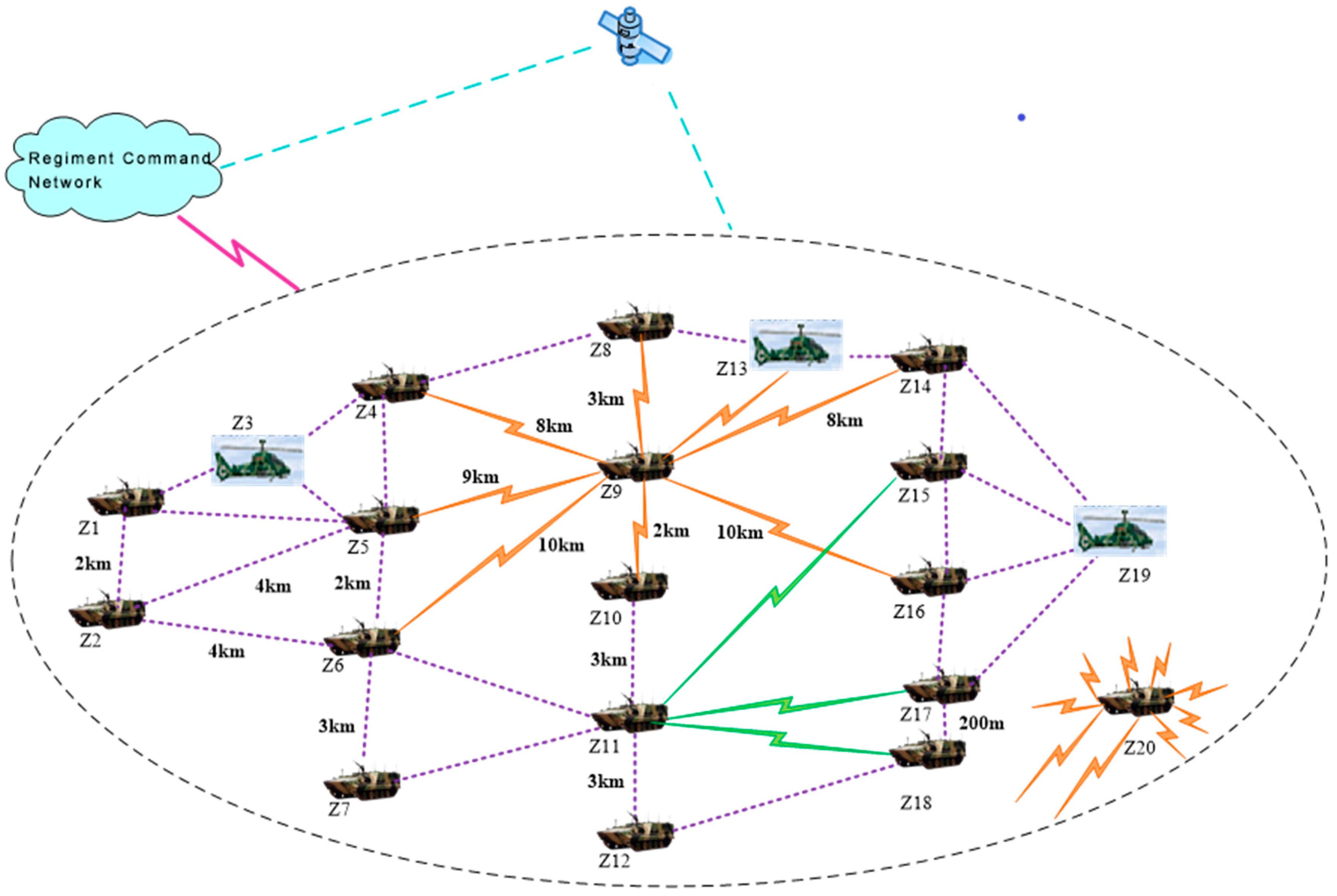
When there is no real-time information to be transmitted, the awareness combat network maintains connectivity as much as possible, shares the situation information between nodes (periodically transmits information such as the location and working state to adjacent nodes), and uses a small transmission power. The running state of the network at this time is referred to as the “flat” state; the state of the awareness combat network when transmitting real-time information is called the “peak” state. The operational environment of the awareness combat network determines that its “flat” state is consistent with the DTN network model, and the network protocol can still work without crashing under the condition of frequent connection and disconnection between moving nodes [
11]. The core idea of the “flat” state routing algorithm is to adopt the method of storing firstly and then looking for an opportunity to forward data packets, overcoming the limitations of traditional routing methods due to limited node caching and the absence of continuously available end-to-end routing, thus realizing the maximum possible transmission of information.
The “flat” state of the awareness combat network is the basis of the “peak” state. It enables each node in the network to obtain time-varying information of neighboring nodes and provides information support for the efficient selection of “peak” state nodes.
The “flat” state routing algorithm, which is based on the AODV protocol, implements the DTN overlay, the DTN message mechanism, the DTN route discovery mechanism, and the store-and-forward mechanism, i.e., the AODV-DTN protocol.
The algorithm is as follows:
- (1)
Adding a DTN overlay immediately to the AODV network layer.
- (2)
Adding new control messages and response messages to implement the DTN message mechanism.
- (3)
Implementing the disruption tolerant function in the DTN overlay. When the link is disconnected, no connection repair is required and data packets continue to be transmitted.
- (4)
When the routing link selected by AODV is about to break, try to find out a route that can replace the broken route. If there is no available route, the delay is tolerated and it waits for another opportunity; once there is an “opportunity link” available, the data packet will continue to be transmitted. An “opportunity link” is a link that is currently temporarily unavailable but may become available as the nodes move or channel interference factors disappear.
- (5)
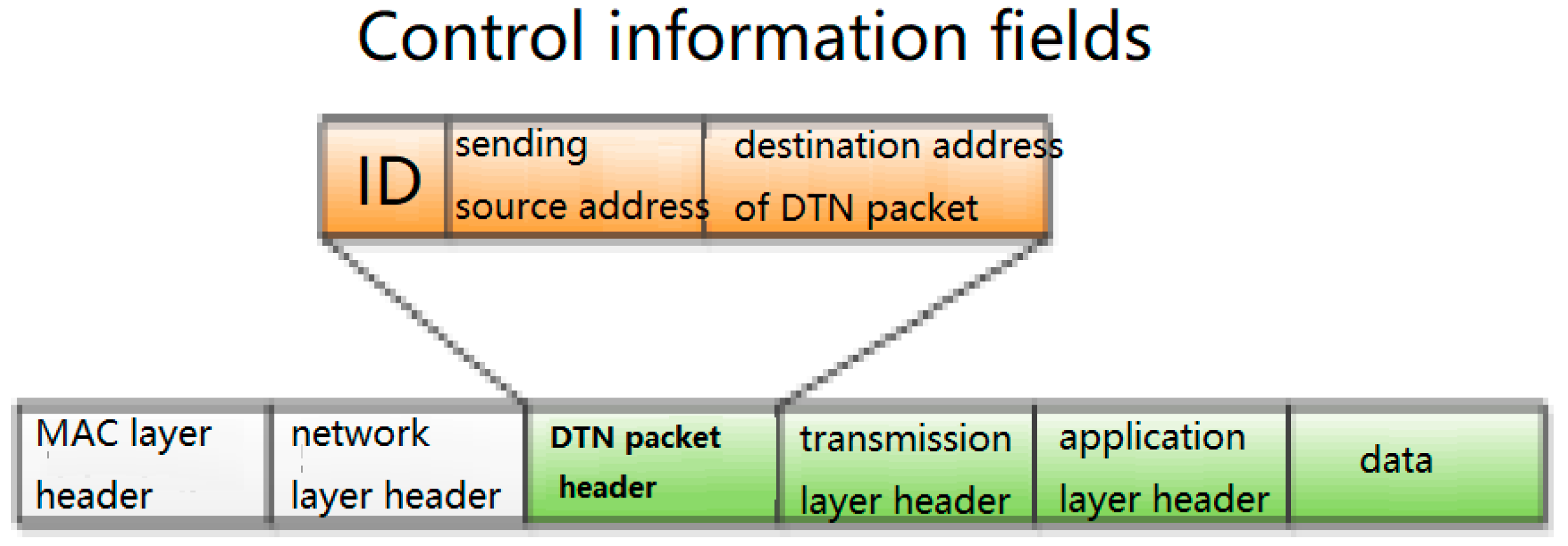
After the routing link is interrupted, the node stores the data packet, namely, the packet is encapsulated into a DTN packet and stored in the storage area of the DTN overlay instead of sending a large number of route control broadcast messages. The DTN packet format is shown in
Figure 3.
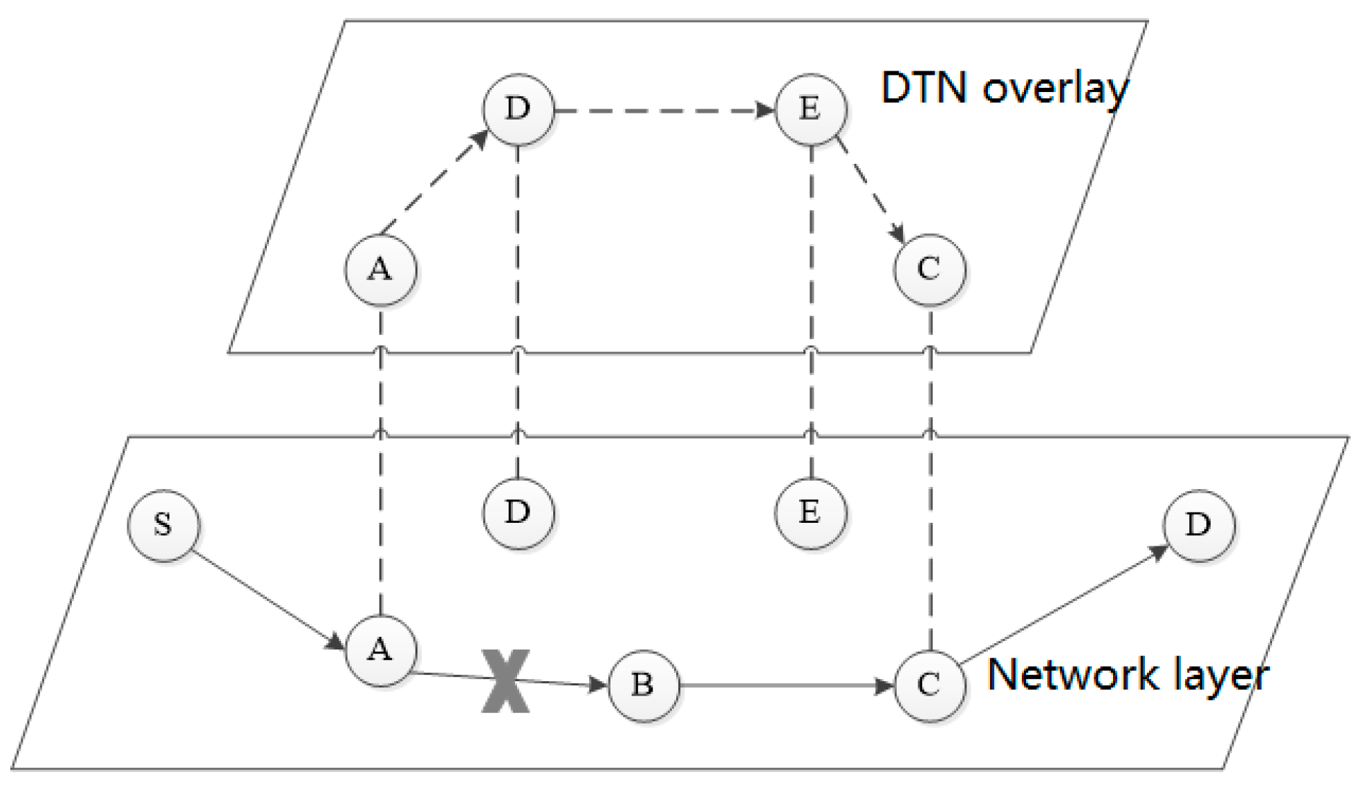
The DTN packet is passed in the DTN overlay, as shown in
Figure 4, from the previous-hop DTN storage area to the next-hop DTN storage area. When the previous-hop node sends a DTN packet, if no response is received from the next-hop node within a certain time range, the previous-hop node sends the DTN packet again from its own DTN storage area. If a response is received from the next-hop node within a certain time range, the previous-hop node deletes the DTN packet from its own DTN storage area. After the link interruption area is skipped, the DTN packet removes the control message restored to the original data packet and will then be passed on to the destination node.
(2) The AODV-DTN flood routing discovers, which uses geo-location information
Each node of the awareness combat network has a high-precision positioning function and the function of real-time perception of its own state. The routing protocol of the awareness combat network should make full use of these capabilities [
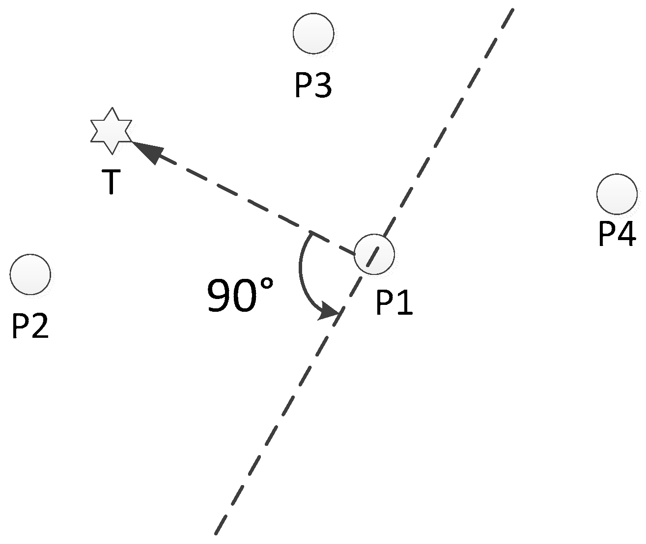
12]. The awareness combat network mainly transmits the target aiming information, and the position information of each node is indispensable. The nodes involved in the routing have a certain locality in the geographical probability distribution, most of which are consistent with the direction of the connection between the source node and the destination node and are located nearby. The AODV-DTN flooding based on geographic location information initiates route discovery, and the location information is used to limit the scope of flooding. With the support of the location information, the node carries out a route discovery process, saves the DTN routing table, and reserves the basic information of the route for the “peak” state of the node. The AODV-DTN flooding using geographic location information as shown in
Figure 5.
The polar coordinate system M is established by taking node P1 as the pole and the direction from P1 to T as the pole axis. The node P2 is at [0°, 90°], node P4 is at (90°~270°), and node P3 is at (270°~360°). If the route extends backward, the flooding range is neighboring nodes within (90°~270°); node P4 is the flooding object and is used as an alternative next hop. In the process of routing, the current node is taken as the pole and the direction from the current node to the previous node is taken as the polar axis to establish a polar coordinate system, the flooding range of which is the same as the above range. If the included angle between the direction from the flooding object to the current node and the polar axis of the polar coordinate system M is an acute angle or a right angle, the flooding object is used as an alternative next hop.
The faster the node moves, the more frequently the Hello messages are sent, and the faster the routing is updated. Nodes send Hello messages to maintain the stability of the network topology.
The flooding cycle is determined by the speed and angle of the node movement. The minimum value of the impact of distance and angle changes on the network routing is used as the update cycle. Assuming that the moving speed of the node is V m/s and the coverage is R m, the flooding will be initiated if the relative angle between nodes changes by more than . The time taken for the angle change to reach is greater than , so the minimum time is used as the update cycle T.
In order to reduce the number of redundant DTN packets in the network, the intermediate node also records the processed DTN packet ID number, and the DTN packet with the same ID number is processed only once according to the above procedure.
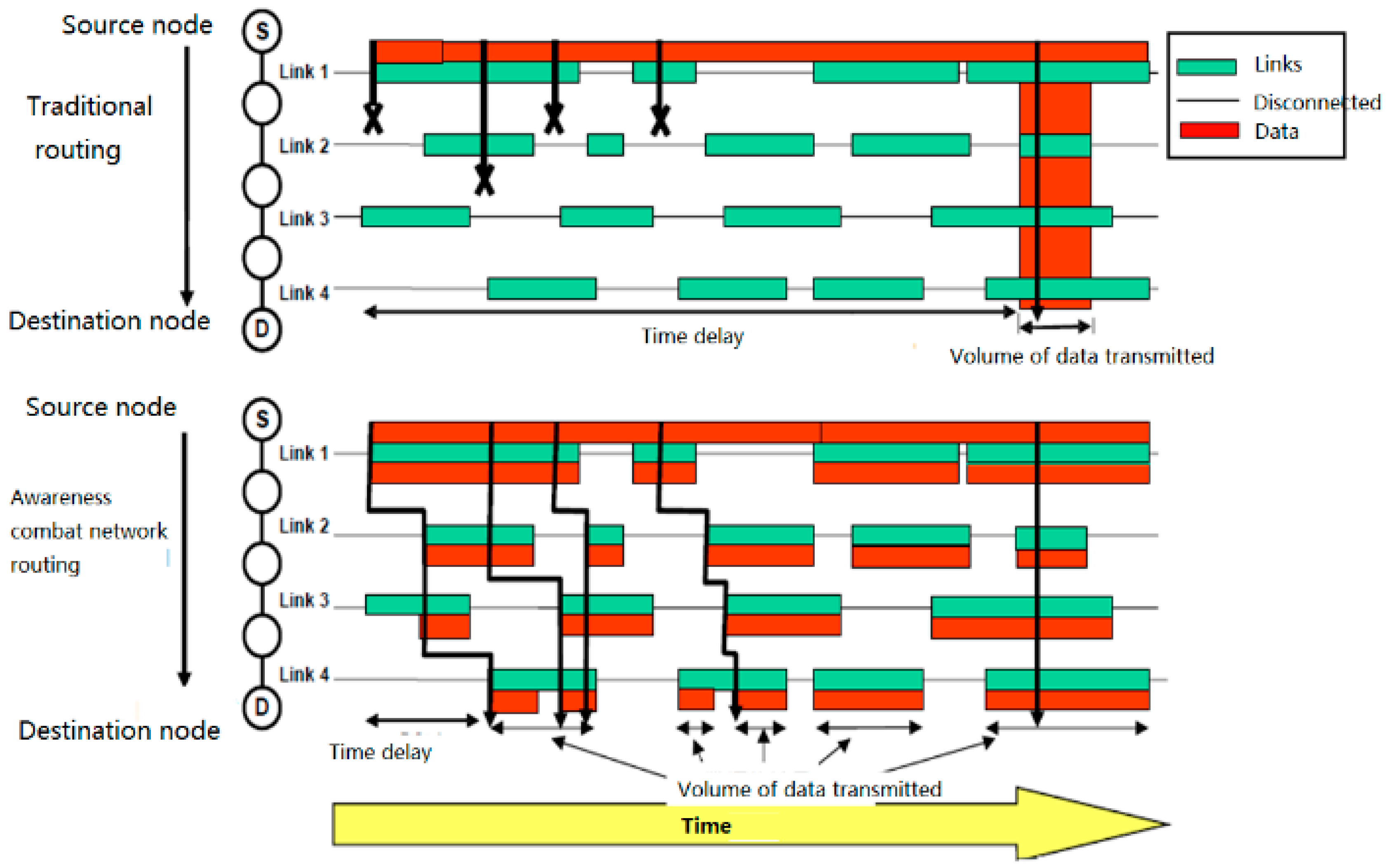
Compared with the traditional routing mechanism, this routing mechanism shortens the time delay and increases the probability of successful data transmission. As shown in
Figure 6, when the green line segments (representing the link connection time) are the same, the red line segments in the lower half (representing the amount of data transmitted) are obviously more than those in the upper half, and the starting positions of the red line segments (representing the delay) are also ahead of those in the upper half.
3.1.2. “Peak” State of the Awareness Combat Network
When the nodes of the awareness combat network transmit data packets of voice and target aiming information, they first use a small transmission power to communicate. The state of the nodes at this time is called the “peak” state in this paper. Although the “peak” state of the awareness combat network must also consider the dynamics of the topology, the most important thing is to consider the stability of the link and ensure the real-time transmission of information. Even if the enemy target information without timeliness is passed to the fire control system, it is useless. Therefore, the network model of the “peak” state is no longer consistent with the DTN network model, but the real-time requirements are added on the basis of the DTN network model. Obviously, allowing interruption and ensuring real-time performance is a contradiction. Although this article cannot completely resolve this contradiction, it can try to use a series of technical means to weaken the degree of contradiction.
Under the condition that the data transmission rate is constant, if the link’s stable duration is much higher than the round trip time (RTT) of the data packet, that is to say the change of the network topology is slow relative to the transmission of the data packet, the link can be considered static during a data packet transmission. The speed at which the network topology changes is quantitatively described by the frequency
of link disconnections on a path. Let
the number of disconnections within time RTT, then”
In the “flat” state of the awareness combat network, the value of is pretty large; while in the “peak” state of the awareness combat network, .
In practical applications, some nodes in the awareness combat network are in the “flat” state, while some nodes are in the “peak” state. The “flat” state guarantees the stable operation of the network. In the case of frequent connections and disconnections between nodes, network routing can converge as quickly as possible. Nodes switch between “flat” and “peak” states depending on the information type of packets they process. If the node processes data packets with strong real-time information such as enemy target information provided for the fire control system and satisfies the minimum stability coefficient, it is in the “peak” state; otherwise it is in the “flat” state. The awareness combat network establishes a target aiming-fire strike data link through “peak” state nodes.
Because of the high-speed movement of the nodes, the network topology changes frequently. This will directly result in unavailability of the selected path and consequently cause a high packet loss rate. Predicting the movement of the vehicle can reduce the impact of network fragmentation. In the process of data transmission, each node used on the path monitors its connectivity to its previous node and the next node and predicts its connection duration to its next node in order to establish a space-time routing table. If the predicted connection time is too short, it will look for another path that can last long enough, and transmit data on the newly established path. If no new path is found nearby, it will send a message to the source node, switch to mobile cellular routing, and let it find a new path in a large range and with less hops.
The stability coefficient
represents the degree of stability of the data link between two nodes. It is the product of the time stability coefficient
and the signal strength
. Set the maximum communication distance between the two nodes in plain areas without an interfering signal as
, the real-time distance between two nodes as
, and the speed of the current node relative to the previous node (assuming that the direction of the nodes away from each other is positive) as
, then:
Packets with real-time information are only transmitted between nodes in the “peak” state, spreading just like sea waves.
The sensor aims and locks the target, and the aiming position and image after aiming are transmitted in real time. The relative position of the sensor platform to the firepower platform is calculated in real time. The above-mentioned aiming position and relative position are added on the fire platform to obtain the aiming position of the fire platform. The image is not processed except for real-time transmission.
Targeting information packets also have the instant speed of the target
and its accelerated speed
. To obtain the accurate instant speed
and accelerated speed
of the target, the reconnaissance vehicle has higher requirements on the aiming method and accuracy of the target. Set the target irradiation interval time
, record the target position
obtained by the two irradiations, the target position
obtained by the previous irradiation, and the target position
obtained by the current irradiation, then:
During the time when the route is interrupted, the attack vehicle assumes that the target uniformly accelerates and estimates the real-time moving distance between the attack vehicle and the target position considering the last time it received the information. In this calculation, is the duration of the route interruption.
When the route is restored, the target location is relocated with the newly received information.
Similarly, when the intermediate node N of the routing forwards data packets, it also adds its own instant speed and accelerated speed fields. During the route interruption, assuming that the next-hop node (N + 1) accelerates uniformly, the location of the next-hop node (N + 1) is estimated, and then the azimuth and distance between nodes N and (N + 1) are calculated according to the motion of node N. If the azimuth exceeds the broadcast range of node N, the distance exceeds the communication range of node N, or the route interruption time exceeds the maximum allowable time , then node N stops forwarding packets to node (N + 1) and re-looks for the next-hop forwarding node. Through such prediction, the node establishes a local space-time routing table.
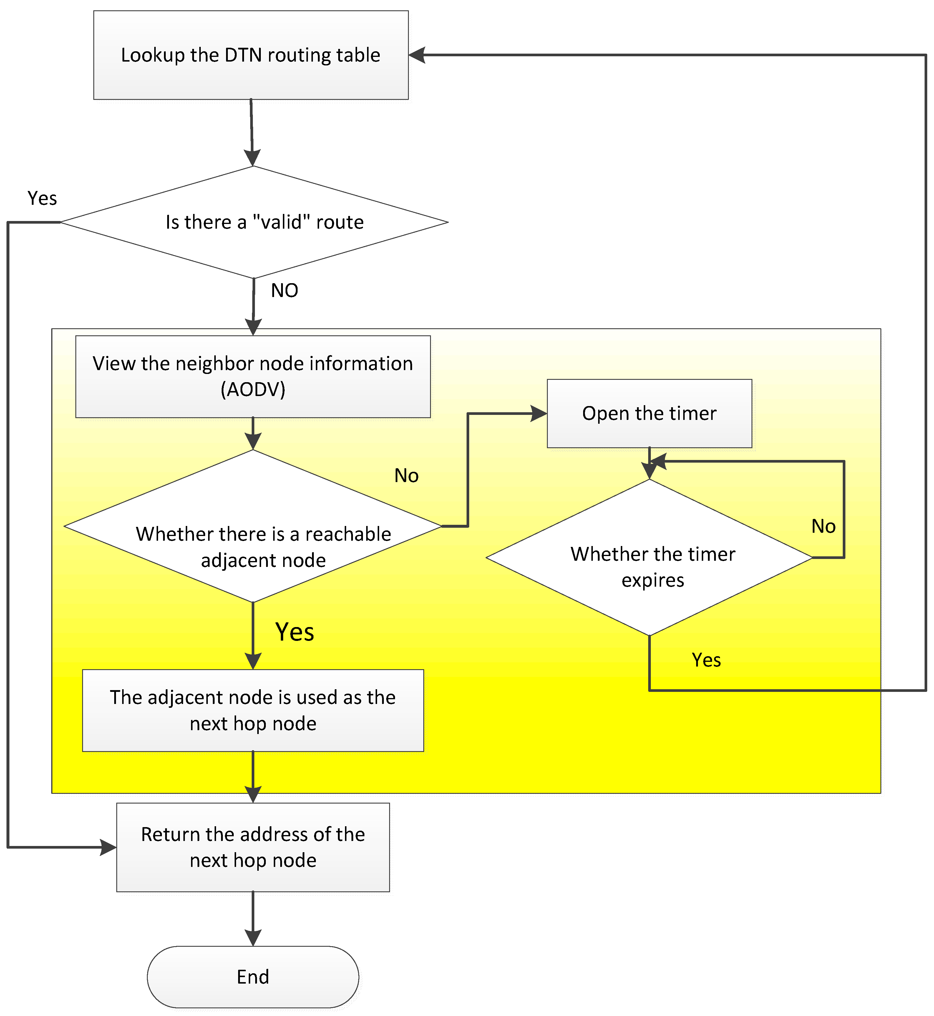
The node state routing algorithm for awareness combat networks is a distributed self-stabilization algorithm that implements rule constraints and information interactions among nodes. It adapts the topological change of each node in the network, maintains routing stability, and reduces routing overhead. The source node that transmits the target aiming information also needs to intelligently select the destination node; it broadcasts messages based on the link layer and carries out one flooding event across the whole network, and the convergence speed is fast. The source node broadcasts a message QD (to look for the destination node); the neighboring node receives the message and inquires its own status across the layers. For the mobile terminal in the “standby” state, if their confidence is within the range of 11 to 19, the message RB (confidence confirmation; the message contains the position coordinates of the node) is returned; in each RB, the source node will select the closet node as the destination node, and if the distance is equal, it will select the node with higher confidence as the destination node. If the source node does not receive any RB message, it switches to mobile cellular routing.
3.1.3. Design and Implementation of Routing Control Selection Module
The design of the routing protocol is composed of five functional modules: initialization and main control module, packet processing and sending module, packet reception processing module, and routing control selection module. Its core is the routing control selection module [
14,
15].
(1) DTN Initialization and Main Control Module
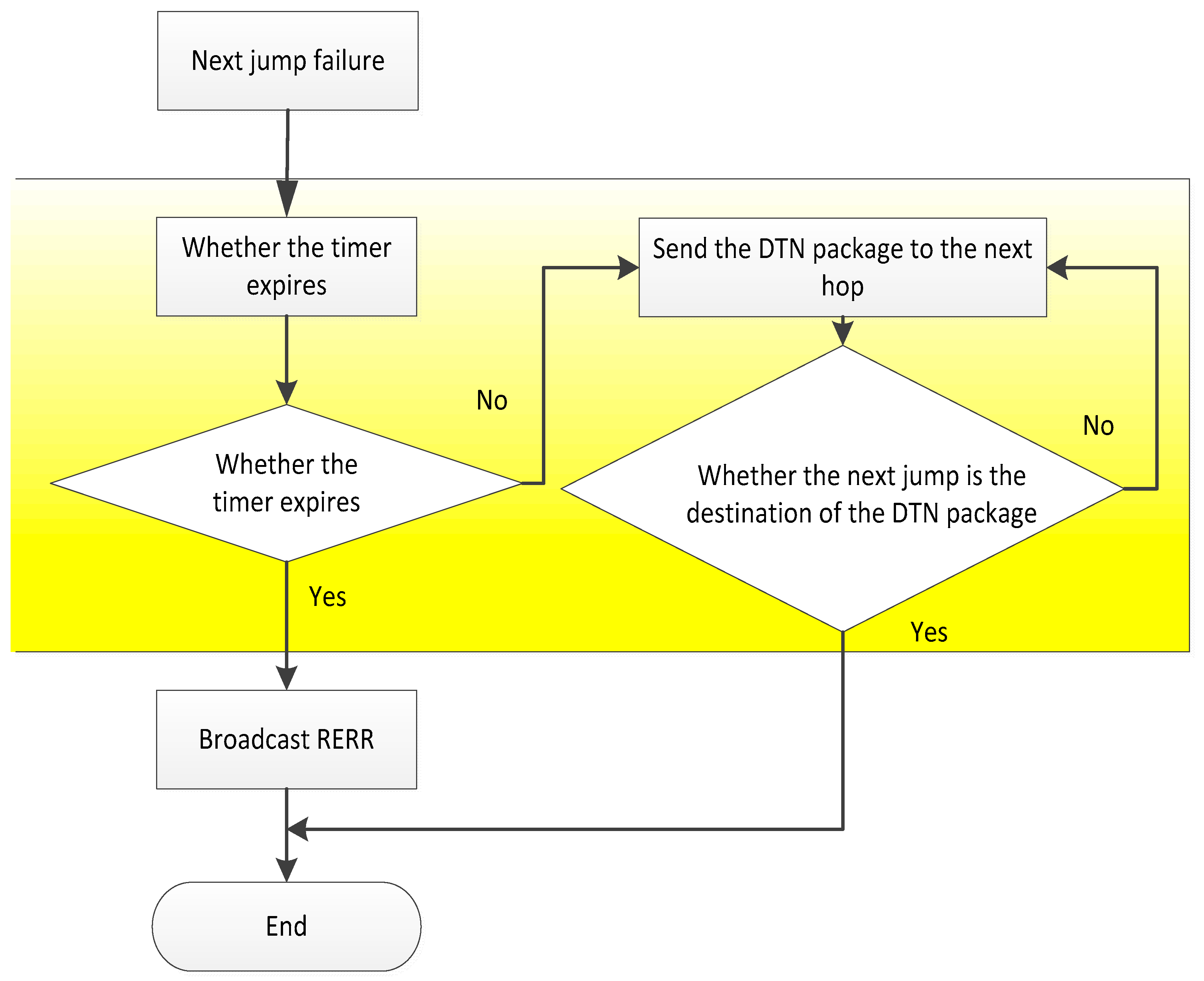
The DTN initialization module is the main control module of the routing mechanism. As long as the node running the AODV protocol receives the link failure message from the node to the next hop node, the DTN initialization module will turn on a timer. If the data packet is successfully passed to the destination node of the DTN before the timer expires, the DTN initialization module sends a “successful” control message to the node running the AODV protocol. If the data packet is not successfully passed to the destination node of the DTN when the timer expires, the DTN initialization module sends a “failure” control message to the node running the AODV protocol. After receiving the message, the node broadcasts the error message RERR to the neighbor node according to the AODV protocol, and runs the routing maintenance or routing of the AODV protocol. In this way, it rediscovers the process, as shown in
Figure 7.
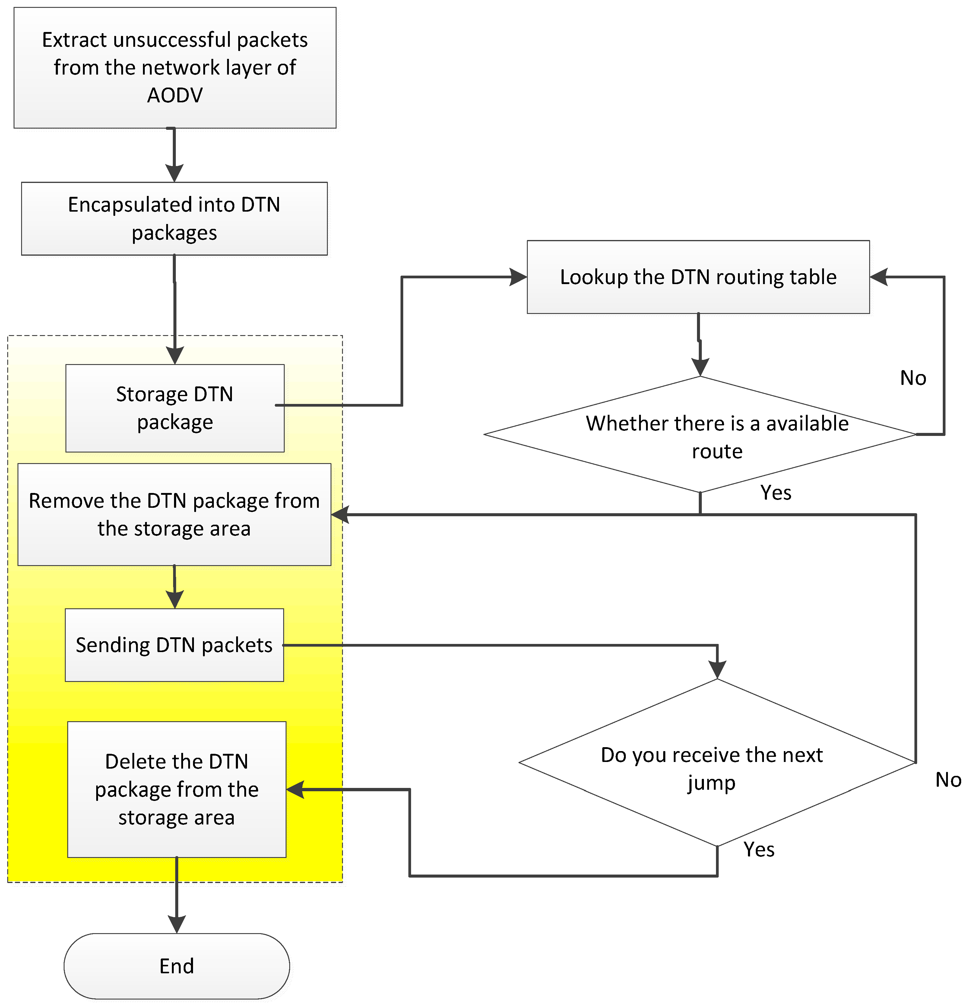
(2) DTN packet processing transmission module
The DTN packet processing module first acquires the data packets which have not been sent by the AODV protocol, and adds the DTN Baotou to the DTN package. The DTN package is stored in the storage area of the DTN overlay layer of the node, and then a copy of the DTN packet is generated as the data to be sent. Query the DTN routing table of the node to get the next hop address. The node sends the DTN packets to be sent to the storage area of the DTN coverage layer of the next hop node. After the next hop node receives the DTN package, it returns a reply message (including the ID number of the DTN packet, the last hop address), and if the node does not receive a reply message from the next hop, a new copy of the DTN packet will be generated, and the ID number of the DTN packet is changed to the next hop node, as shown in
Figure 8.
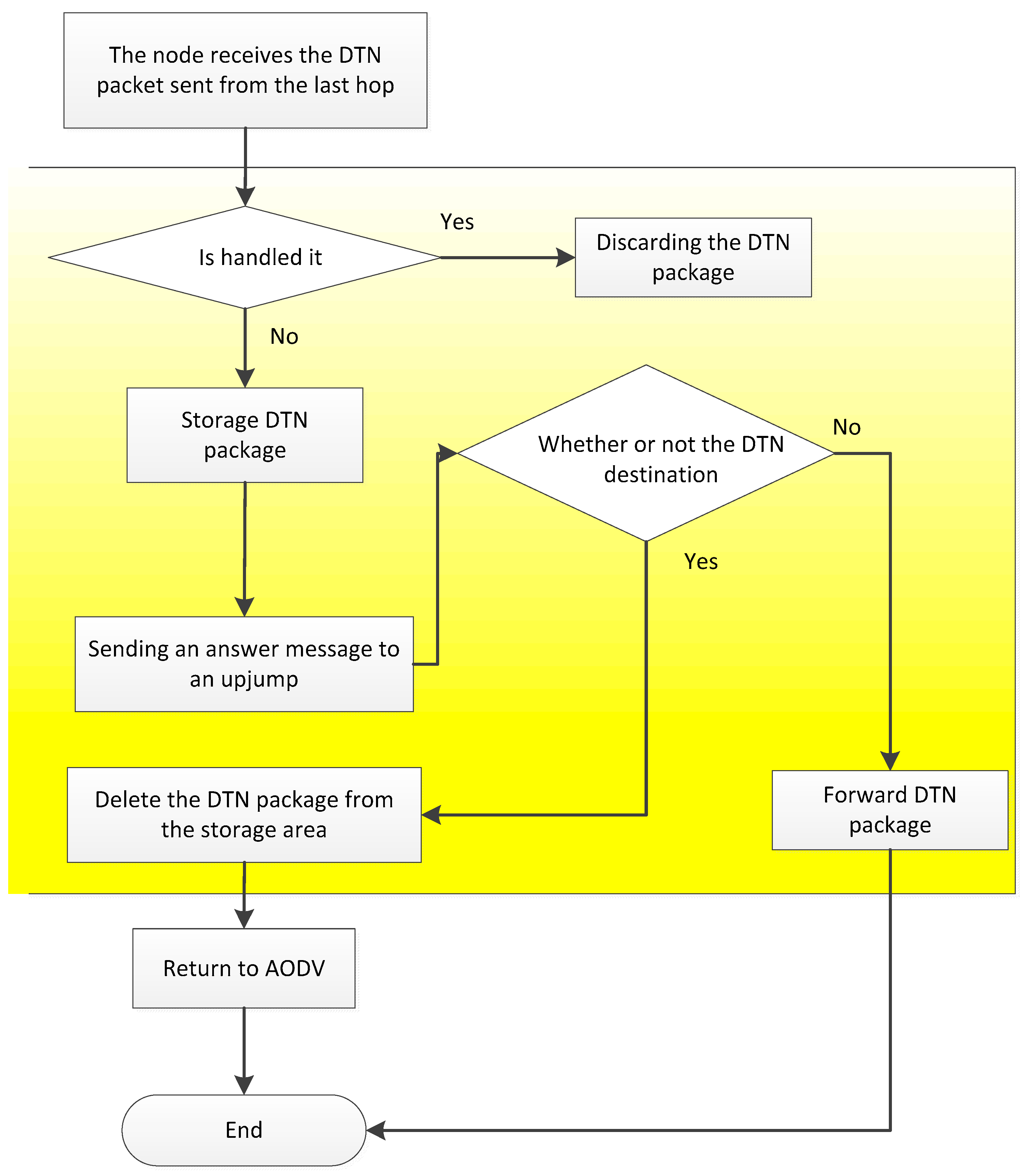
(3) DTN packet reception processing module
When the DTN packet sent by the last hop node is received, the next hop node determines whether the DTN packet has been processed through the ID number of the DTN package. If the package is processed, it is discarded; if it is not processed, it is put in the storage area and a reply message is sent to the next hop node. If the node is the destination node of the DTN package, the node will remove the DTN Baotou, restore the DTN packet into the original data packet, and continue to run the AODV protocol to handle the packet. The node receives the reply message from the next hop node and removes the DTN packet in the storage area according to the DTN package ID in the reply message, as shown in
Figure 9.
(4) DTN routing control selection module
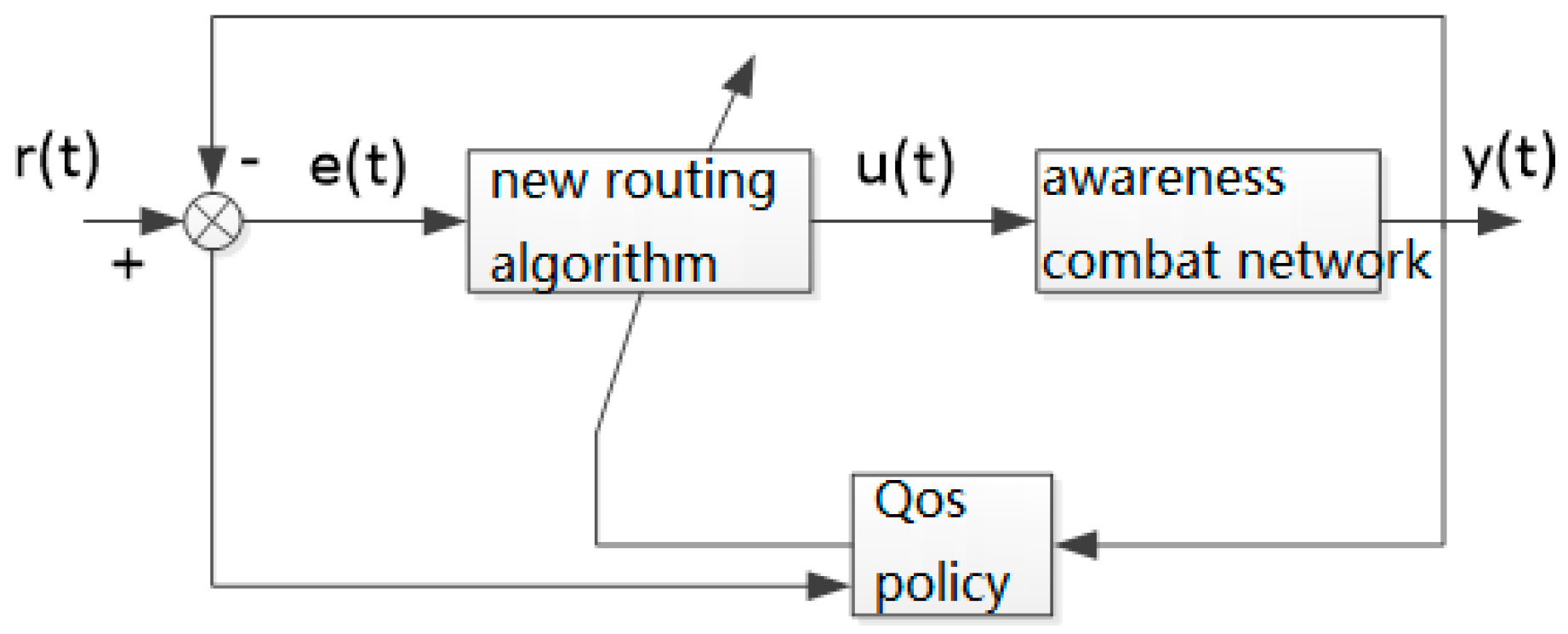
It is important to make full use of AODV’s routing discovery mechanism to build the DTN routing table. The DTN routing table records every route established by route discovery when running AODV protocol, and updates only with time without deleting routing records. When the link is disconnected or the node moves so that the adjacent nodes are no longer adjacent, the relevant routing marks in the DTN routing table are “invalid”. When link recovery or node mobility allows nodes to have new neighbor nodes, the relevant routing marks in the DTN routing table are “valid”.
Nodes look for whether the DTN routing table has a marked “valid” route to the destination node. If there is, the address of the next hop node is returned; if not, the DTN route discovery is performed, as shown in
Figure 10. The node obtains the adjacent node information by running the AODV protocol to see if there is a reachable neighbor node. If the node returns the address of the neighbor node, the DTN packet is sent to the neighbor node, and then the DTN packet is forwarded by the neighbor node. If there is no reachable neighbor node, the timer is opened, waiting for the valid link to appear until the timer expires, and the DTN routing table is re-searched.
In the process of information transfer, the DTN overlay is added to the AODV protocol, and the packets received (including network management data, node location, and combat status data, etc.) are encapsulated into DTN packets, stored in local nodes, and the DTN packets are carried in the process of node movement, and link connectivity between adjacent nodes is sought as a link between the nodes. When the road is connected, it is forwarded. The routing between nodes in the “Ping” state is distributed only in adjacent nodes, that is, hopping to the hopping route. There is no route between the source end and the destination end at the same time. The “peak” state nodes set up the space-time routing table according to the information obtained in the “flat” state, and forward the packets according to the AODV protocol of the geographic location assisted routing (including the target real-time/near real-time information data for fire control).


