Time Dependence of Wetting Behavior Upon Applying Hierarchic Nano-Micro Periodic Surface Structures on Brass Using Ultra Short Laser Pulses

Abstract
:1. Introduction
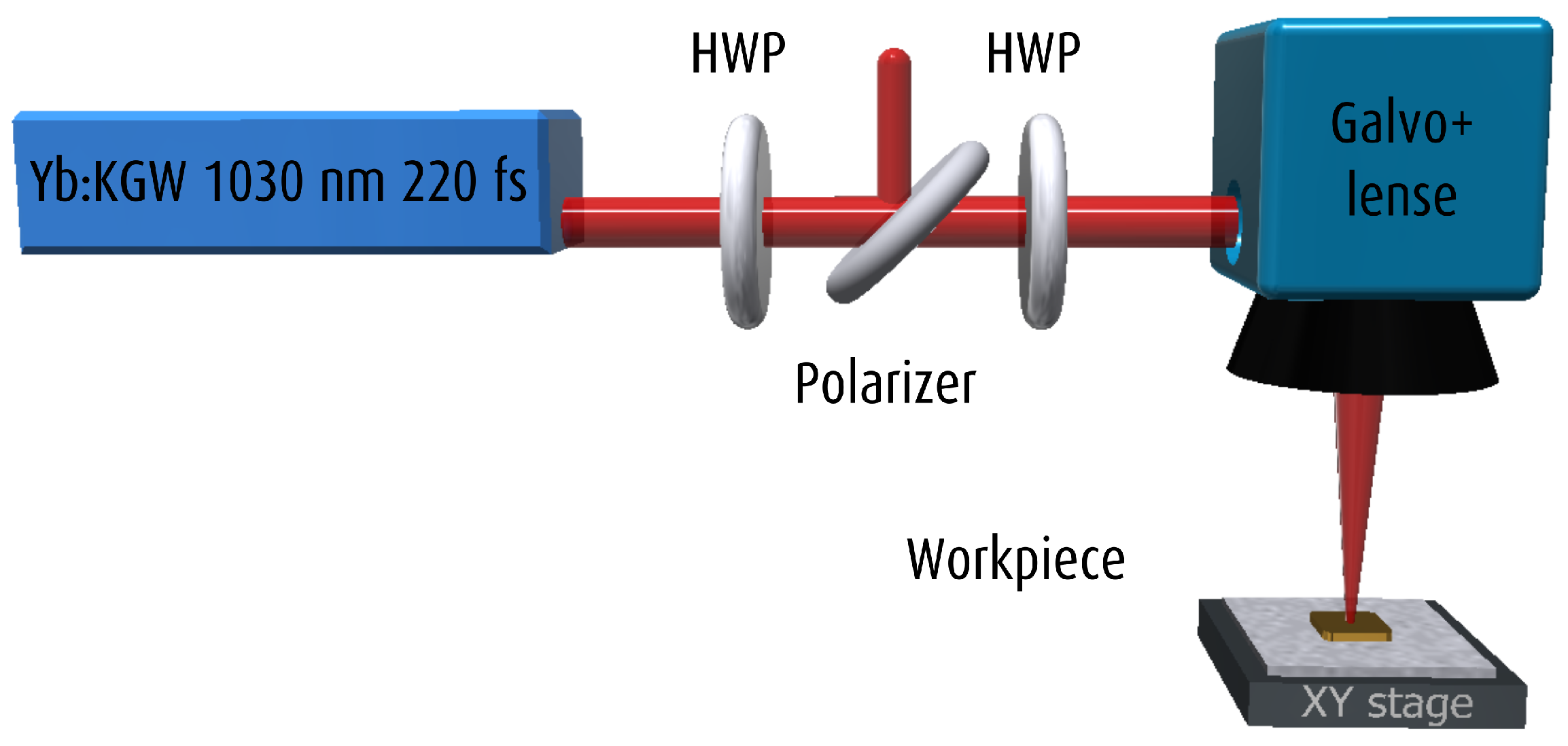
2. Experimental
3. Results and Discussion
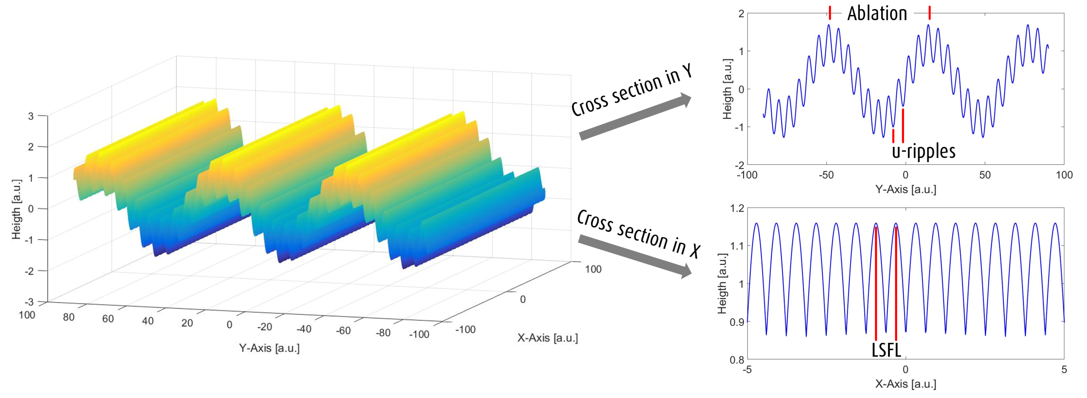
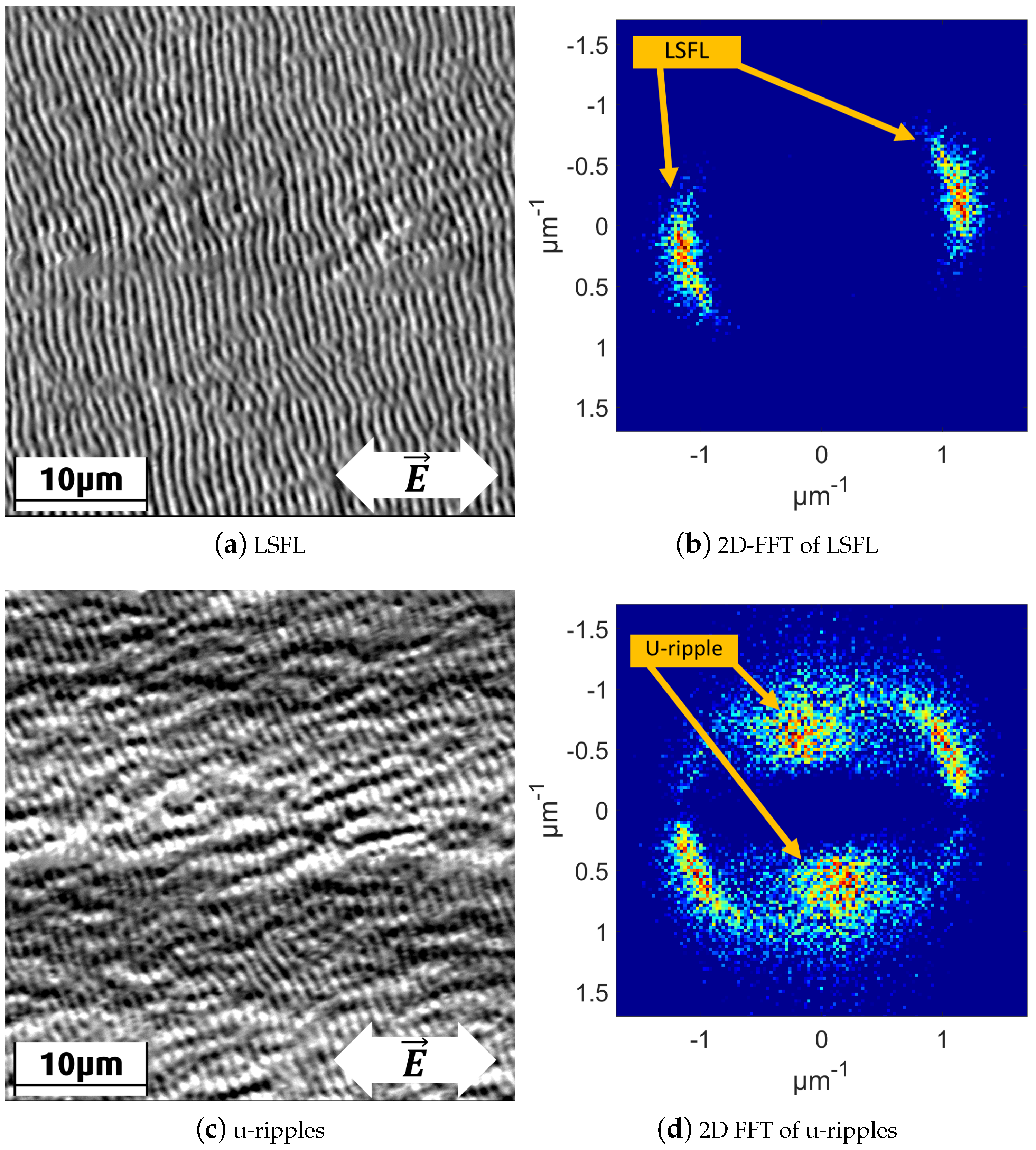
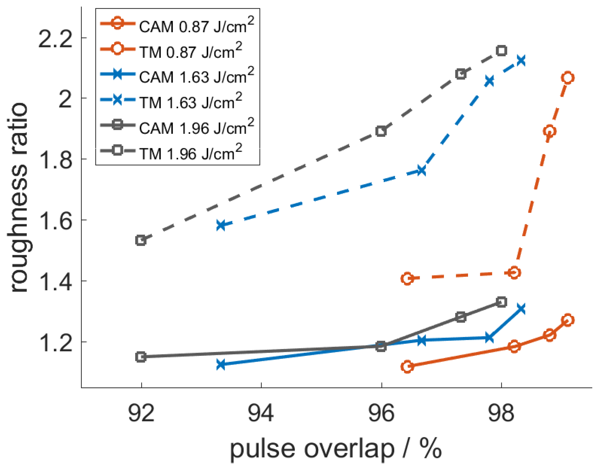
3.1. Modulation Length and Depth Analysis of Laser-Structured Surfaces
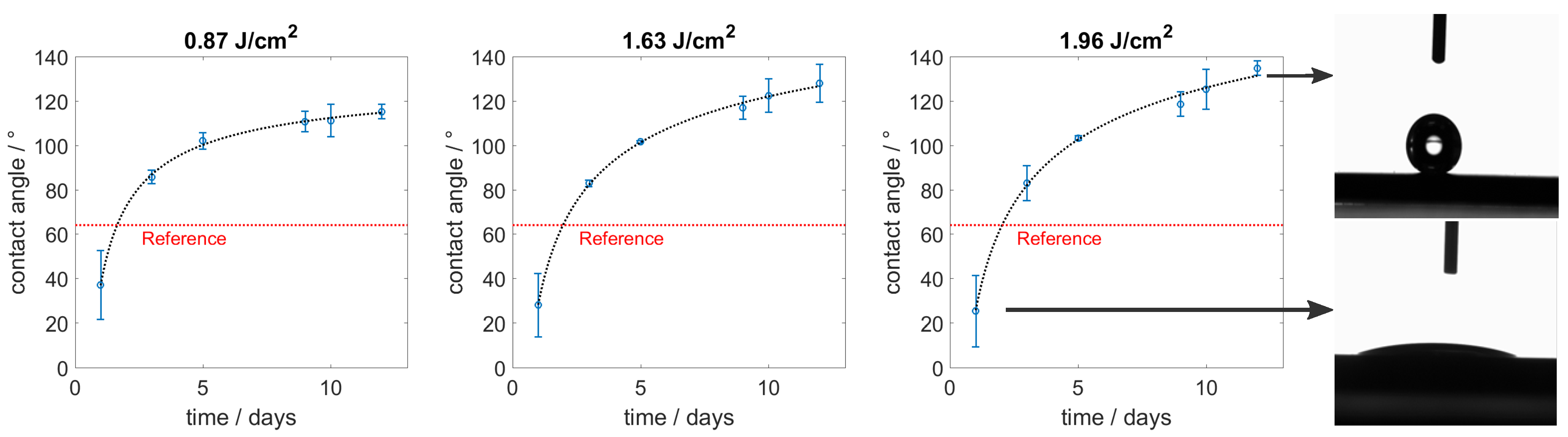
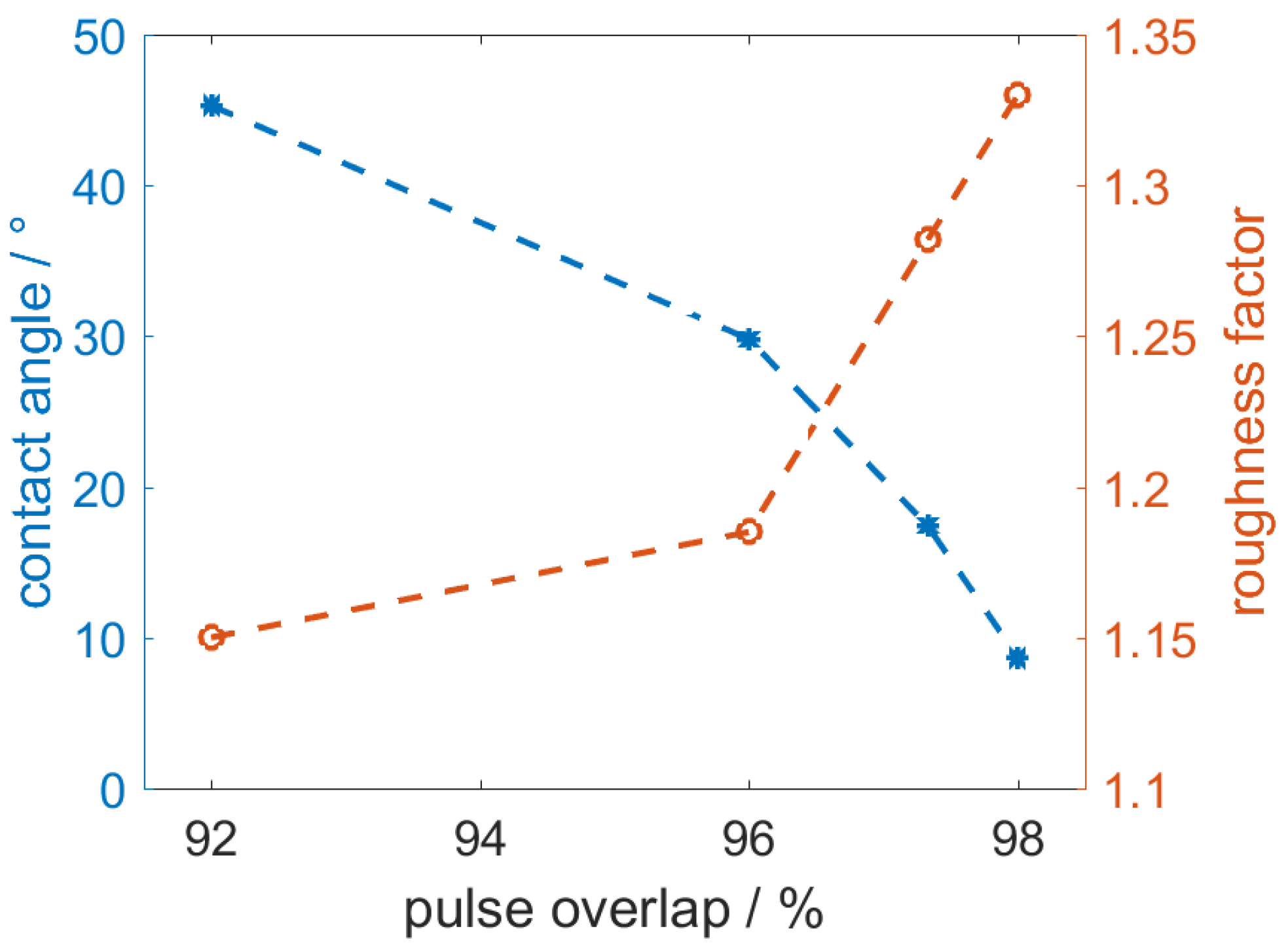
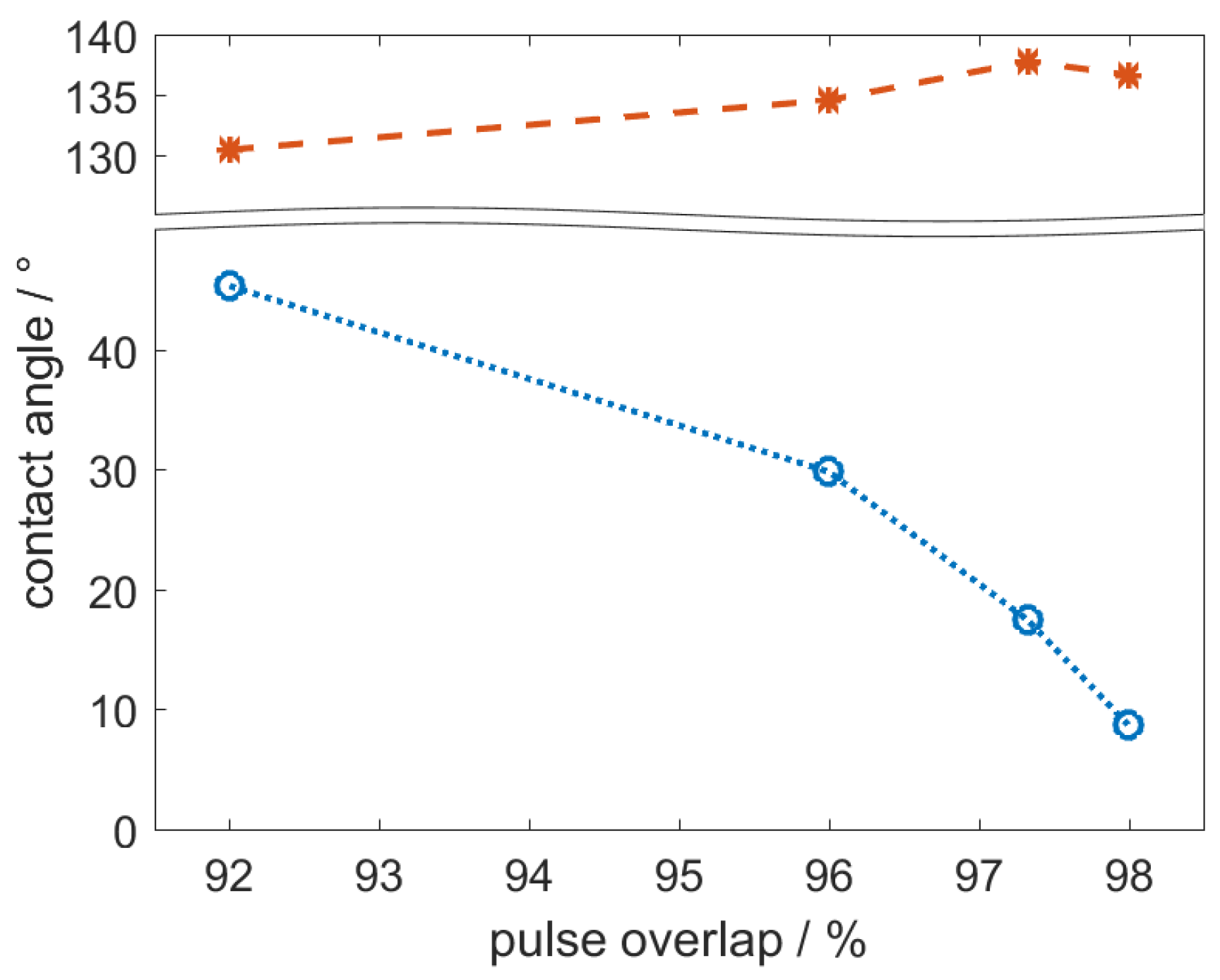
3.2. Wetting Behavior
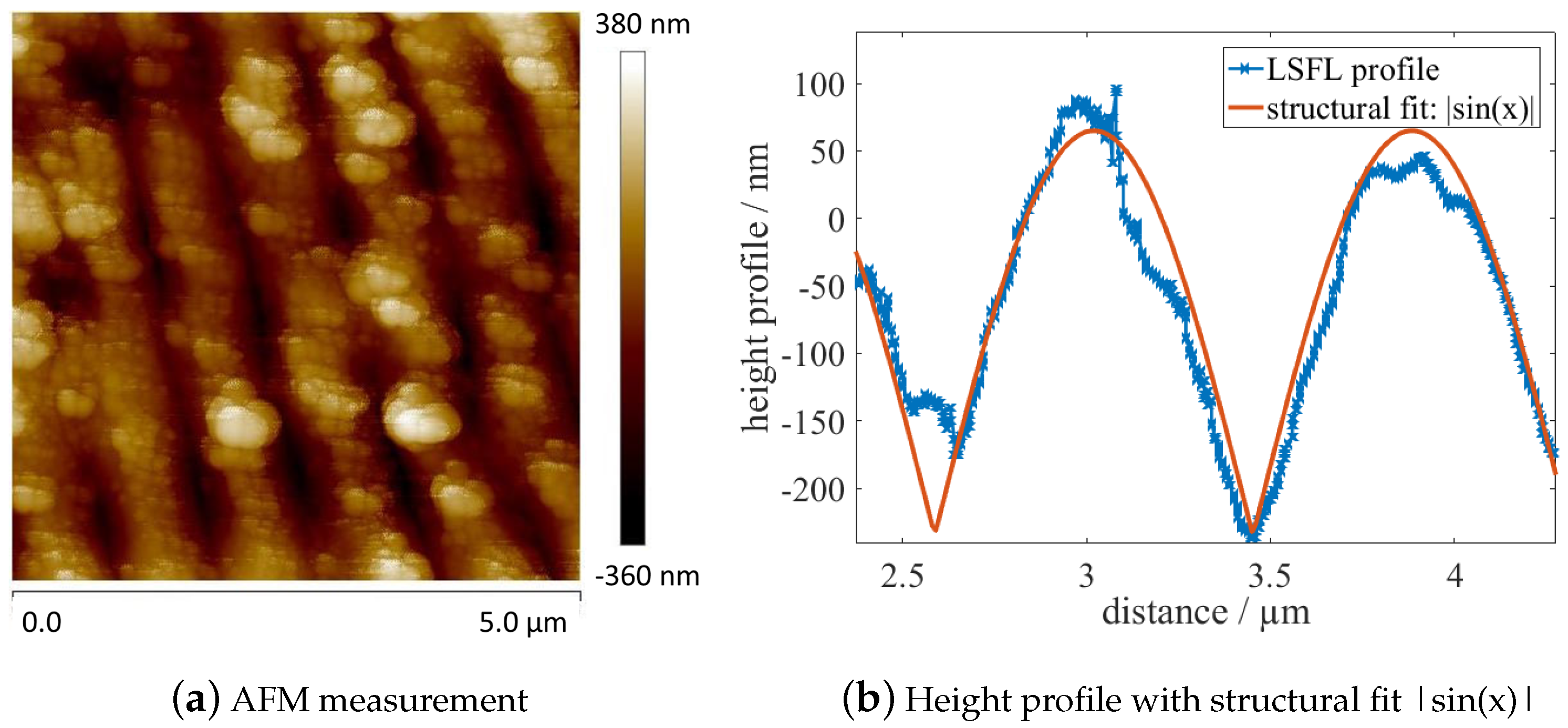
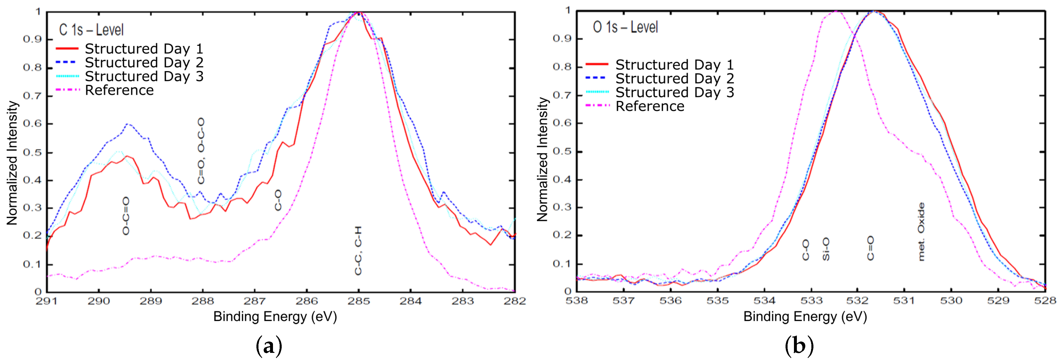
3.3. Structural Characterization
4. Conclusions
Author Contributions
Conflicts of Interest
References
- Birnbaum, M. Semiconductor Surface Damage Produced by Ruby Lasers. J. Appl. Phys. 1965, 36, 3688–3689. [Google Scholar] [CrossRef]
- Bonse, J.; Krüger, J.; Höhm, S.; Rosenfeld, A. Femtosecond laser-induced periodic surface structures. J. Laser Appl. 2012, 24, 042006. [Google Scholar] [CrossRef]
- Bonse, J.; Munz, M.; Sturm, H. Structure formation on the surface of indium phosphide irradiated by femtosecond laser pulses. J. Appl. Phys. 2005, 97, 013538. [Google Scholar] [CrossRef] [Green Version]
- Bonse, J.; Krüger, J. Pulse number dependence of laser-induced periodic surface structures for femtosecond laser irradiation of silicon. J. Appl. Phys. 2010, 108, 034903. [Google Scholar] [CrossRef]
- Zhang, W.; Cheng, G.; Feng, Q. Unclassical ripple patterns in single-crystal silicon produced by femtosecond laser irradiation. Appl. Surf. Sci. 2012, 263, 436–439. [Google Scholar] [CrossRef]
- Skolski, J.Z.P. Inhomogeneous Absorption of Laser Radiation: Trigger of LIPSS Formation. J. Laser Micro/Nanoeng. 2013, 8, 1–5. [Google Scholar] [CrossRef]
- Bashir, S.; Shahid Rafique, M.; Husinsky, W. Femtosecond laser-induced subwavelength ripples on Al, Si, CaF2 and CR-39. Nucl. Instrum. Methods Phys. Res. Sect. B Beam Int. Mater. Atoms 2012, 275, 1–6. [Google Scholar] [CrossRef]
- Dusser, B.; Sagan, Z.; Soder, H.; Faure, N.; Colombier, J.P.; Jourlin, M.; Audouard, E. Controlled nanostructrures formation by ultra fast laser pulses for color marking. Opt. Exp. 2010, 18, 2913–2924. [Google Scholar] [CrossRef] [PubMed]
- Dufft, D.; Rosenfeld, A.; Das, S.K.; Grunwald, R.; Bonse, J. Femtosecond laser-induced periodic surface structures revisited: A comparative study on ZnO. J. Appl. Phys. 2009, 105, 034908. [Google Scholar] [CrossRef]
- Seifert, G.; Kaempfe, M.; Syrowatka, F.; Harnagea, C.; Hesse, D.; Graener, H. Self-organized structure formation on the bottom of femtosecond laser ablation craters in glass. Appl. Phys. A 2005, 81, 799–803. [Google Scholar] [CrossRef]
- Schwarz, S.; Rung, S.; Hellmann, R. Generation of laser-induced periodic surface structures on transparent material-fused silica. Appl. Phys. Lett. 2016, 108, 181607. [Google Scholar] [CrossRef]
- Wallat, K.; Dörr, D.; Le Harzic, R.; Stracke, F.; Sauer, D.; Neumeier, M.; Kovtun, A.; Zimmermann, H.; Epple, M. Cellular reactions toward nanostructured silicon surfaces created by laser ablation. J. Laser Appl. 2012, 24, 042016. [Google Scholar] [CrossRef]
- Wang, Z.; Zhao, Q.; Wang, C. Reduction of Friction of Metals Using Laser-Induced Periodic Surface Nanostructures. Micromachines 2015, 6, 1606–1616. [Google Scholar] [CrossRef]
- Athanasiou, C.E.; Hongler, M.O.; Bellouard, Y. Unraveling Brittle-Fracture Statistics from Intermittent Patterns Formed During Femtosecond Laser Exposure. Phys. Rev. Appl. 2017, 8, 293. [Google Scholar] [CrossRef]
- Madeo, J.; Margiolakis, A.; Zhao, Z.Y.; Hale, P.J.; Man, M.K.L.; Zhao, Q.Z.; Peng, W.; Shi, W.Z.; Dani, K.M. Ultrafast properties of femtosecond-laser-ablated GaAs and its application to terahertz optoelectronics. Opt. Lett. 2015, 40, 3388–3391. [Google Scholar] [CrossRef] [PubMed]
- Pazokian, H.; Selimis, A.; Barzin, J.; Jelvani, S.; Mollabashi, M.; Fotakis, C.; Stratakis, E. Tailoring the wetting properties of polymers from highly hydrophilic to superhydrophobic using UV laser pulses. J. Micromechan. Microeng. 2012, 22, 035001. [Google Scholar] [CrossRef]
- Ocaña, J.L.; Jagdheesh, R.; García-Ballesteros, J.J. Direct generation of superhydrophobic microstructures in metals by UV laser sources in the nanosecond regime. Adv. Opt. Technol. 2016, 5, 87–93. [Google Scholar] [CrossRef]
- Li, B.j.; Li, H.; Huang, L.J.; Ren, N.F.; Kong, X. Femtosecond pulsed laser textured titanium surfaces with stable superhydrophilicity and superhydrophobicity. Appl. Surf. Sci. 2016, 389, 585–593. [Google Scholar] [CrossRef]
- Martínez-Calderon, M.; Rodríguez, A.; Dias-Ponte, A.; Morant-Miñana, M.C.; Gómez-Aranzadi, M.; Olaizola, S.M. Femtosecond laser fabrication of highly hydrophobic stainless steel surface with hierarchical structures fabricated by combining ordered microstructures and LIPSS. Appl. Surf. Sci. 2016, 374, 81–89. [Google Scholar] [CrossRef]
- Zorba, V.; Persano, L.; Pisignano, D.; Athanassiou, A.; Stratakis, E.; Cingolani, R.; Tzanetakis, P.; Fotakis, C. Making silicon hydrophobic: Wettability control by two-lengthscale simultaneous patterning with femtosecond laser irradiation. Nanotechnology 2006, 17, 3234–3238. [Google Scholar] [CrossRef]
- Ngo, C.V.; Chun, D.M. Fast wettability transition from hydrophilic to superhydrophobic laser-textured stainless steel surfaces under low-temperature annealing. Appl. Surf. Sci. 2017, 409, 232–240. [Google Scholar] [CrossRef]
- Yang, Z.; Tian, Y.L.; Yang, C.J.; Wang, F.J.; Liu, X.P. Modification of wetting property of Inconel 718 surface by nanosecond laser texturing. Appl. Surf. Sci. 2017, 414, 313–324. [Google Scholar] [CrossRef]
- Rajab, F.H.; Liu, Z.; Li, L. Production of stable superhydrophilic surfaces on 316L steel by simultaneous laser texturing and SiO 2 deposition. Appl. Surf. Sci. 2018, 427, 1135–1145. [Google Scholar] [CrossRef]
- Luo, B.H.; Shum, P.W.; Zhou, Z.F.; Li, K.Y. Preparation of hydrophobic surface on steel by patterning using laser ablation process. Surf. Coat. Technol. 2010, 204, 1180–1185. [Google Scholar] [CrossRef]
- Martínez-Calderon, M.; Rodrígueza, A.; Diasa, A.; Gómez-Aranzadia, M.; Olaizolaa, S.M. Femtosecond laser manufacturing of highly hydrophobic hierarchical structures fabricated by combining surface microstructures and LIPSS. In Proceedings of the Lasers in Manufacturing Conference; Wissenschaftliche Gesellschaft Lasertechnik e.V.: Erlangen, Germany, 2015. [Google Scholar]
- Bizi-bandoki, P.; Valette, S.; Audouard, E.; Benayoun, S. Time dependency of the hydrophilicity and hydrophobicity of metallic alloys subjected to femtosecond laser irradiations. Appl. Surf. Sci. 2013, 273, 399–407. [Google Scholar] [CrossRef]
- Raimbault, O.; Benayoun, S.; Anselme, K.; Mauclair, C.; Bourgade, T.; Kietzig, A.M.; Girard-Lauriault, P.L.; Valette, S.; Donnet, C. The effects of femtosecond laser-textured Ti-6Al-4V on wettability and cell response. Mater. Sci. Eng C Mater. Biol. Appl. 2016, 69, 311–320. [Google Scholar] [CrossRef] [PubMed]
- Ta, D.V.; Dunn, A.; Wasley, T.J.; Kay, R.W.; Stringer, J.; Smith, P.J.; Connaughton, C.; Shephard, J.D. Nanosecond laser textured superhydrophobic metallic surfaces and their chemical sensing applications. Appl. Surf. Sci. 2015, 357, 248–254. [Google Scholar] [CrossRef]
- Kietzig, A.M.; Negar Mirvakili, M.; Kamal, S.; Englezos, P.; Hatzikiriakos, S.G. Laser-patterned super-hydrophobic pure metallic substrates: Cassie to wenzel wetting transitions. J. Adhes. Sci. Technol. 2011, 25, 2789–2809. [Google Scholar]
- Wenzel, R.N. Surface Roughness and Contact Angle. J. Phys. Colloid Chem. 1949, 53, 1466–1467. [Google Scholar] [CrossRef]
- Okamuro, K.; Hashida, M.; Miyasaka, Y.; Ikuta, Y.; Tokita, S.; Sakabe, S. Laser fluence dependence of periodic grating structures formed on metal surfaces under femtosecond laser pulse irradiation. Phys. Rev. B 2010, 82. [Google Scholar] [CrossRef] [Green Version]
- Golosov, E.V.; Emel’yanov, V.I.; Ionin, A.A.; Kolobov, Y.R.; Kudryashov, S.I.; Ligachev, A.E.; Novoselov, Y.N.; Seleznev, L.V.; Sinitsyn, D.V. Femtosecond laser writing of subwave one-dimensional quasiperiodic nanostructures on a titanium surface. JETP Lett. 2009, 90, 107–110. [Google Scholar] [CrossRef]
- Yu, J.; Lu, Y. Laser-induced ripple structures on Ni–P substrates. Appl. Surf. Sci. 1999, 148, 248–252. [Google Scholar] [CrossRef]
- Van Ta, D.; Dunn, A.; Wasley, T.J.; Li, J.; Kay, R.W.; Stringer, J.; Smith, P.J.; Esenturk, E.; Connaughton, C.; Shephard, J.D. Laser textured surface gradients. Appl. Surf. Sci. 2016, 371, 583–589. [Google Scholar]
- Van Ta, D.; Dunn, A.; Wasley, T.J.; Li, J.; Kay, R.W.; Stringer, J.; Smith, P.J.; Esenturk, E.; Connaughton, C.; Shephard, J.D. Laser textured superhydrophobic surfaces and their applications for homogeneous spot deposition. Appl. Surf. Sci. 2016, 365, 153–159. [Google Scholar]


| Spatial Wavelength/nm | ||||
| 2.5 J/m | 5 J/m | 7.5 J/m | 10 J/m | |
| 0.87 J/cm | 905 | 902 | 886 | 879 |
| 1.63 J/cm | 901 | 894 | 884 | 872 |
| 1.96 J/cm | 897 | 891 | 882 | 869 |
| Spatial Wavelength/nm | ||||
| 2.5 J/m | 5 J/m | 7.5 J/m | 10 J/m | |
| 0.87 J/cm | 1316 | 1557 | 1788 | 1808 |
| 1.63 J/cm | 1247 | 1316 | 1733 | 1812 |
| 1.96 J/cm | 1280 | 1339 | 1709 | 1800 |
| Spatial Wavelengthm | ||||
| 2.5 J/m | 5 J/m | 7.5 J/m | 10 J/m | |
| 0.87 J/cm | 25.8 | 27.8 | 28 | 28.4 |
| 1.63 J/cm | 24.5 | 29.6 | 32.1 | 31.2 |
| 1.96 J/cm | 25.2 | 33 | 32.3 | 33.2 |
© 2018 by the authors. Licensee MDPI, Basel, Switzerland. This article is an open access article distributed under the terms and conditions of the Creative Commons Attribution (CC BY) license (http://creativecommons.org/licenses/by/4.0/).
Share and Cite
Rung, S.; Schwarz, S.; Götzendorfer, B.; Esen, C.; Hellmann, R. Time Dependence of Wetting Behavior Upon Applying Hierarchic Nano-Micro Periodic Surface Structures on Brass Using Ultra Short Laser Pulses. Appl. Sci. 2018, 8, 700. https://doi.org/10.3390/app8050700
Rung S, Schwarz S, Götzendorfer B, Esen C, Hellmann R. Time Dependence of Wetting Behavior Upon Applying Hierarchic Nano-Micro Periodic Surface Structures on Brass Using Ultra Short Laser Pulses. Applied Sciences. 2018; 8(5):700. https://doi.org/10.3390/app8050700
Chicago/Turabian StyleRung, Stefan, Simon Schwarz, Babette Götzendorfer, Cemal Esen, and Ralf Hellmann. 2018. "Time Dependence of Wetting Behavior Upon Applying Hierarchic Nano-Micro Periodic Surface Structures on Brass Using Ultra Short Laser Pulses" Applied Sciences 8, no. 5: 700. https://doi.org/10.3390/app8050700