An Active Seat Controller with Vehicle Suspension Feedforward and Feedback States: An Experimental Study

Centre for Power Transmission and Motion Control, Department of Mechanical Engineering, University of Bath, Claverton Down, Bath BA2 7AY, UK
*
Author to whom correspondence should be addressed.
Appl. Sci. 2018, 8(4), 603; https://doi.org/10.3390/app8040603
Submission received: 21 February 2018
/
Revised: 28 March 2018
/
Accepted: 5 April 2018
/
Published: 11 April 2018
Abstract
:Active seat suspensions can be used to reduce the harmful vertical vibration of a vehicle’s seat by applying an external force using a closed loop controller. Many of the controllers found in the literature are difficult to implement practically, because they are based on using unavailable or difficult and costly measurements. This paper presents both simulation and experimental studies of five novel, simple, and cost-effective control strategies to be used for an active seat suspension in order to improve ride comfort at low frequencies below 20 Hz. These strategies use available and measurable feedforward (preview) information states from the vehicle secondary suspension, as well as feedback states from the seat suspension, together with gains optimised to minimise the occupant vibration. The gains were optimised using a genetic algorithm (GA), with a fitness function based on the seat effective amplitude transmissibility (SEAT) factor. Constraints on the control force and the seat suspension stroke were also included in the optimisation algorithm. Simulation and laboratory experimental tests were carried out to assess the performance of the proposed controllers according to the ISO 2631-1 standard, in both the frequency and time domains with a range of different road profiles. The experimental tests were performed using a multi-axis simulation table (MAST) and a physical active seat suspension configured as a hardware-in-loop (HIL) simulation with a virtual linear quarter vehicle model (QvM). The results demonstrate that the proposed controllers substantially attenuate the vertical vibration at the driver’s seat compared with both a passive and a proportional-integral-derivative (PID) active seat suspension and thus improve ride comfort together with reducing vibration-linked health risks. Moreover, experimental results show that employing both feedforward information and feedback vehicle body and seat acceleration signals in the controller provides isolation performance gains of up to 19.5 dB over the human body sensitivity frequency range and improves the ride comfort in terms of the SEAT factor and the weighted root mean square (RMS) seat acceleration by at least 25% when compared with a passive system, irrespective of vehicle forward speed.

1. Introduction
It is well known that the human body is particularly sensitive to whole body vibration (WVB) over a frequency range of 4–8 Hz in the vertical direction caused by road roughness transmitted via the vehicle body. This will affect the ride comfort and can be harmful if experienced over a prolonged period [1]. Much research has been undertaken in this area, covering secondary spring/damper vehicle and seat suspensions. The latter option of a seat suspension has some advantages as it can directly reduce the WBV, is cost-effective and can provide practicable solutions. There are three types of seat suspensions, namely, passive, semi-active and active. With passive seat suspensions, the vibration attenuation performance is limited due to the fixed characteristics of the suspension elements and, thus, they are only effective over a limited frequency range. In contrast, the suspension characteristics of semi-active systems are controlled by using adjustable suspension elements, such as magnetorheological dampers (MR) [2] or electro-rheological (ER) dampers [3]. Whilst, semi-active systems are safe, cost-effective and require low power consumption, the isolation performance is still limited, as a semi-active suspension can dissipate energy and re-distribute this within the system but cannot add energy [4]. An active system can dissipate and/or release energy from the system by applying an external force. This increases the attenuation performance of this system over a wider frequency range when compared with passive and semi-active seat suspensions. However, the performance of these systems depends on many factors, such as the actuation and sensing systems as well as the control approach that is employed to generate the required control force [5]. In addition, there is a compromise between improving the ride quality while also limiting the seat suspension travel within its allowable physical limits and consequently, comprehensive research in the literature has been conducted regarding a range of control approaches. Kawana and Shimogo [6] applied optimal control theory in designing an active seat suspension for a heavy truck using an electric servomotor and ballscrew mechanism in which the system state’s variables were obtained by integrating the corresponding associated measured acceleration signals. An active vehicle suspension using a robust H∞ and output feedback controller based on a three degree of freedom (DOF) quarter vehicle suspension with a human body model was investigated by Gu et al. [7]. Although the controller claimed to use available states, the absolute velocities of the sprung and unsprung masses were acquired by integrating the associated acceleration signals. In a paper by Stein [8] a hybrid feedforward-feedback controller based on the sky-hook principle was investigated in order to attenuate the vertical vibration of a driver’s seat using an electropneumatic active seat suspension. Sun et al. [9] modified a dynamic output feedback H∞ controller over a limited frequency range for an active seat suspension. Wu and Chen [10] studied experimentally and in simulation the application of a hybrid control approach that comprised of an adaptive controller that combined a filtered-x least mean square (Fx-LMS) and a robust H∞ feedback controller for an active seat suspension. Beside the complexity of the proposed controller it failed to significantly attenuate the vibration at the driver’s seat in the case of a random broadband vibration disturbance which is the most common type of road input. Maciejewski et al. [11] experimentally investigated an active pneumatic seat suspension using a triple-feedback control algorithm that utilised available and measurable system states. As a result of the complexity associated with the pneumatic system and its limited frequency response, the active system was only effective in reducing vertical vibration at low frequencies, less than 4 Hz and did not perform well at higher frequencies that can cause significant discomfort.
An H∞ controller with friction compensation based on available seat states was proposed by Ning et al. [12] to reduce low frequency vertical vibration in the driver’s seat, based on available seat states while [13] developed a Takagi-Sugeno fuzzy logic controller with a disturbance observer for an active suspension to reduce low-frequency vertical vibration at the driver’s seat using available and measurable seat states. Gan et al. [14] experimentally applied an adaptive controller with a Filtered-x least-mean square algorithm for an active seat suspension and an artificial neural network (ANNC) and a fuzzy logic (FLC) controller for an active seat suspension was investigated in [15]. Song et al. [16] developed a hybrid adaptive fuzzy sliding mode controller for a vehicle suspension system with a disturbance estimator. The experimental results of applying this control approach for a semi-active suspension system using a magnetorheological damper (MRD) showed a better vibration attenuation performance compared with passive and other alternative suspensions.
Many of the active vibration controllers presented in the literature are either expensive or difficult to implement in practice. This is due to the fact that some of these strategies use unavailable states, such as the absolute velocity of the driver or seat. Some studies argue that numerical integration of the acceleration signals can be used to acquire these states, although the precision of the resulting states can be affected by noise and offsets [17]. In addition, using an observer to estimate the necessary unavailable states is impractical as it requires an accurate system model, which is difficult to guarantee [18]. Consequently, it is an important issue from both a cost and reliability point of view to develop an active seat suspension with a controller that requires only accessible and inexpensive system states.
Preview Control
Bender [19], who first introduced the principle of preview information in vehicle suspensions, suggested that the use of preview information can effectively enhance their performance. Preview information from the road disturbance is used in the control approach, before the road disturbances act on the vehicle body. This approach can decrease the controller and the actuator response times, and, hence, improve the suspension performance [20,21].
There are two approaches to preview control: ‘’look ahead’’, where the road disturbances are sensed as preview information to the controller of the active suspension, before these disturbances act on the vehicle and ‘’wheelbase’’ controllers where instead of acquiring preview information from the road disturbances, they are sensed from the dynamic changes of the front wheels and later used as preview information to control the active rear suspension. The advantages and disadvantages of each approach are explained in more details in the review paper of [20].
The motivation of this work is to develop a novel control approach for an active seat suspension based on the principle of feedforward or ‘preview’ information, as well as available and measurable feedback states. The preview information that is used in this active seat controller is based on the dynamic changes in the vehicle secondary (spring/damper) suspension, together with feedback states obtained or derived from available measurements. The use of a preview signal can provide a significant improvement in the active seat suspension performance by preparing the controller to cancel the effects of disturbances in advance of their action on the seat and occupant.
In a previous study by Alfadhli et al. [22] the concept of using such preview information in an active seat suspension was investigated experimentally. The results showed that this approach significantly reduces the vertical vibration at the driver’s seat when compared with a passive system. In addition, in a recent simulation based study by the authors [23], this concept was successfully applied to an active seat in a multi-degree of freedom full vehicle model incorporating the roll and pitch modes.
In the paper presented here, a further five simple and novel active seat suspension controllers using preview information from the vehicle suspension states, as well as available feedback states from the seat are proposed. The performance of these active suspension controllers is demonstrated initially through simulation and is then validated through experimental tests.
2. Control Strategy
This section presents the governing equations of the active seat and quarter car simulation model and a series of candidate control strategies. In addition, the approach used to design the structure of each controller using a genetic optimisation algorithm is outlined.
2.1. Integrated Mathematical Model
To design and evaluate the performance of an active seat suspension, mathematical models for the vehicle and the seat suspension, as well as the driver’s body are required. The vehicle is characterised by a linear quarter vehicle model (QvM) with two DOFs. This approach was used as it has been widely studied in the literature and can be used to analyse the vertical motion of the vehicle and passengers [24,25]. Both the seat suspension and the driver’s body are represented by a single degree of freedom linear lumped spring-damper-mass system, as shown in Figure 1, in which , , , and are the driver body, the seat mass along with the vehicle sprung, and the unsprung masses, respectively. The displacements of the corresponding masses in the vertical direction are , , , and , respectively, while is the road excitation displacement. The governing equations of the vertical motions of the integrated model are given as:
where is control force that is generated by the actuator.
2.2. Active Seat Suspension Control Strategies
In order to design a practical and cost-effective active seat suspension, the cost and number of sensors that provide the controlling signals have to be considered. Accordingly, in this study five simple control strategies have been designed to attenuate the vertical vibration at the driver’s seat. The concept inherent in these control strategies is that the control force is assumed to be a linear function of the preview information from the vehicle suspension combined with feedback states, as given in Table 1.
All of the controllers, A1 to A5, use preview signals from the vehicle suspension, namely, the vehicle suspension displacement and velocity . Controller A1 employs only preview information while A2 uses the preview information and the acceleration of the sprung mass in the QvM. A3 uses preview information together with the acceleration of the seat, whereas both the seat and the sprung mass accelerations are used in the controller A4. Finally, instead of using acceleration signals, the controller A5 utilises the preview information as well as the feedback states of the seat suspension’s travel and velocity.
The parameters (q’s) and (r’s) in Table 1 refer to the gains of the feed-forward (preview information) and feedback states for each control strategy, respectively. These were obtained by optimising a fitness function to improve the vibration isolation performance of the seat and subsequently to provide improved ride comfort for the driver. As a result of the improved attenuation of the seat acceleration, the controllers increased the travel of the seat suspension which, itself, is physically limited [26,27] and, consequently, both the suspension travel and actuator force limitations were included in the optimization process.
There are many methods for assessing ride comfort either using the time or the frequency domains, such as the root mean square (RMS) of the seat acceleration or the power spectrum density (PSD) function, respectively. However, the human body sensitivity to acceleration depends on the vibration frequencies and directions [1,28]. For instance, it is well known that the human body is most sensitive to vertical vibration in the frequency range of 4–8 Hz. Consequently, in this study, the fitness function that was used in the gain optimisation process was based on the seat effective amplitude transmissibility (SEAT) factor, which is defined as the ratio between the acceleration at the seat to that at the base of the seat [1]. This is mathematically given by (Maciejewski, Meyer et al. 2009) [29]:
where is the RMS of the seat acceleration and is the RMS of the sprung mass acceleration. The subscript means that these acceleration values are weighted according to the frequency weighting function in the vertical direction given by the ISO-2361-1 standard. The optimisation problem for each controller can be summarised as follows:
where is the maximum allowable seat travel which was assumed to be 45.0 mm [28] in this study. In addition, to solve the above optimization problem a road profile is required to excite the QvM. Due to the fact that most road profiles are random and involve the majority of the human frequency sensitivity range, a random road profile is a critical part of the optimisation process. The random road profile used in this work was based on ISO 8606 (ISO 8608:1995) which suggests an approximated formula of the PSD function of the road roughness [30]. The above optimisation problem was solved using the genetic algorithm (GA) optimization technique as it has the ability to search randomly over a wide range of feasible solutions and, thus, can offer an efficient global optimum solution [24,26,31]. Further details on the generation of artificial random road profiles, as well as the optimisation process are presented by the authors in [22].
In addition to the SEAT factor that was used to evaluate the active seat ride quality, two further criteria were considered, as given in the following sections [28].
2.3. Ride Comfort Level
This method which assesses the ride comfort qualitatively [28,32] depends on the total frequency-weighted RMS acceleration (ISO 2631-1), , given as:
However, the vibrations in this study only occur in the Z-axis, therefore the above equation is rewritten as:
where and is the frequency-weighted acceleration given as follows:
where is the frequency-weighting at the i-th one-third octave band and is the corresponding RMS acceleration. ISO 2631-1 provides approximated levels of comfort associated with vibration environments based on the frequency-weighted RMS acceleration as given in Table 2.
2.4. Daily Threshold Limit Values (TLVs)
ISO 2631-1 suggests daily TLVs that represent the daily safe zone levels of an occupational exposure to whole-body vibration depending on the weighted-frequency RMS acceleration as given in the Annex B of the ISO 2631-1.
2.5. Identifying the Passive Seat Characteristics
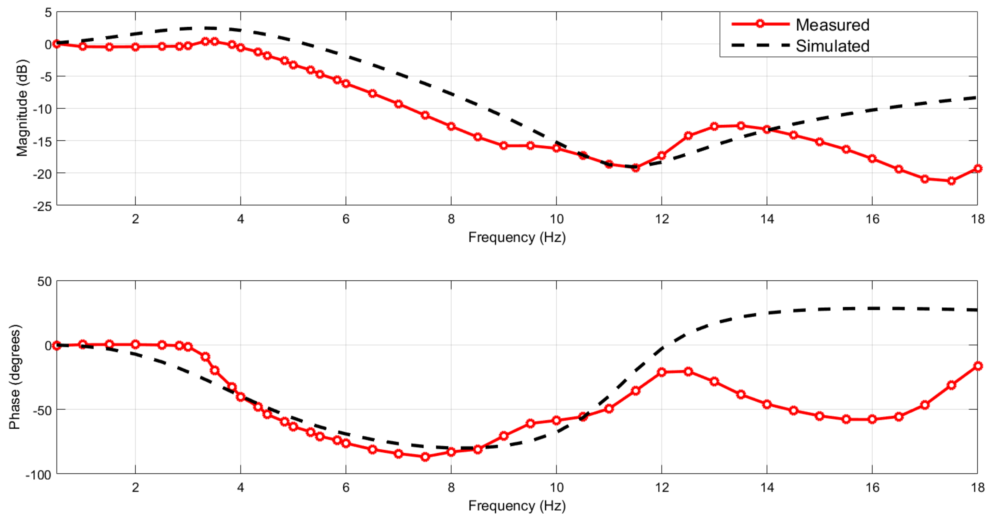
The integrated model shown in Figure 1 was modelled using Simulink and the MATLAB) (MATLAB 2017, MathWorks, Cambridge, CB4 0HH, UK) GA optimisation tool box was utilised to solve the optimisation problem. To make the application more realistic, the characteristics of the passive seat suspension (, , and ), as well as the driver ( and ) were estimated based on experimental tests of the passive seat suspension with a dummy that represented a driver using the experimental test rig that is explained in more details in Section 4. These parameter values were determined by fitting the measured vertical acceleration transmissibility of the passive seat suspension with respect to the seat base (the MAST) to that obtained from the simulated model as illustrated in Figure 2. A swept sinusoidal displacement signal with amplitude of 10.0 mm and frequency range of 0.5–18 Hz was used to excite the MAST. The resulting seat pan and MAST accelerations were measured using a sampling frequency of 10 kHz and filtered using a low-pass filter with a cut-off frequency of 200 Hz.
The simulation model is simplified to ease the optimization process but captures enough accuracy to yield a good overall result from the controller. It can clearly be seen that there is a good agreement between the measured and simulated seat acceleration transmissibility over the frequency range of interest (<12 Hz). A fundamental natural frequency of the passive seat suspension and the dummy was observed around 3.5 Hz together with additional passive seat suspension and dummy higher order dynamics above 12 Hz that were not predicted by the simplified model. While we recognise that the simplified model does not provide a good fit above frequencies of 12 Hz, it is later demonstrated that this mismatch does not unduly affect the controller performance, which is good evidence of robustness in the controller design.
The QvM parameters used in this study and the estimated parameters of the passive seat suspension and the dummy are listed in Table 3 while the GA parameters are given in Table 4. Subsequently, the simulated optimum controller gains for each controller strategy were obtained, as given in Table 5. Once these had been obtained, the performance of the proposed control strategies was evaluated firstly in simulation and then validated experimentally.
3. Simulation Studies
In this section the effectiveness of the proposed control strategies is examined in both the frequency and time domains using different road inputs, including random and bump profiles. In addition, to show the advantages of these strategies they were also compared to both a passive seat suspension and an active seat suspension with a PID controller, thus, the following section gives a brief explanation about the design of the PID controller.
3.1. PID Controller
A PID controller is a standard controller that has been used in many industrial applications. The actuator force of the active seat suspension utilising a PID controller can be expressed follows:
where , , and are the proportional, integral, and derivative gains of the PID, respectively, and is the error signal between the desired and the actual seat acceleration signals. This error signal is given as follows:
where is the desired seat acceleration. However, in this study, it was assumed to be zero.
The values of the PID gains were obtained in the same manner as the preview controller, using the previous optimisation problem given in Equation (6). This aims to minimize the weighted seat acceleration while limiting the seat suspension displacement and active force demand. Thus, the values of the PID gains are .
3.2. Frequency Domain Performance Evaluation
The simulated acceleration transmissibilities of the active seat suspension with respect to the sprung mass acceleration using the proposed control strategies (A1–A5) are compared with those of a PID active seat suspension and the passive seat suspension as shown in Figure 3. Results are presented over the frequency range (0.5–18 Hz). It can be seen that for all the proposed control strategies the active seat suspension provides better vibration attenuation compared with both the passive and the PID active seat suspension systems, although this performance deteriorates at very low frequencies, less than 1 Hz. In general, the controller A3, which utilises feedforward preview information signals together with the feedback seat acceleration signal, delivers the best vibration attenuation over the whole frequency range. The next best performance is achieved by the simplest controller A2, which uses only preview information from the vehicle suspension. Although controller A5 provides the best vibration attenuation performance over the human body sensitive frequency range (4–8 Hz) compared with other strategies, its performance reduces outside this frequency range. All proposed control strategies significantly outperform the tuned passive and PID active control systems. Controller A4, which employs both preview information and the feedback seat and sprung mass acceleration signals, performs very similarly to the controller A3.
3.3. Time Domain Performance Evaluation
3.3.1. Random Road Profile
In this section the effectiveness of the proposed strategies in improving ride comfort is evaluated when the QvM is subject a random road profile at different vehicle speeds. The road profile used in this study is of a class E (very poor) according to ISO 8606 standard, which has a road roughness of . For the sake of brevity, only the time responses in terms of the seat acceleration and seat suspension travel, as well as the PSD of the seat acceleration at a vehicle speed of 60 km/h is presented. The results are presented in Figure 4, Figure 5 and Figure 6. From Figure 4 it can be seen that the proposed controllers are more effective in reducing the seat acceleration when compared with the passive system. Controllers A3, A4, and A5, which use both feedforward preview information together with feedback signals, provide the best performance, while the PID active seat suspension slightly reduces the seat acceleration compared with the passive system as shown in Figure 4f. As expected, the superior vibration attenuation of the proposed control strategies results in increased seat suspension travel compared with the passive alternative. This is illustrated in Figure 5 in which controller A5 generates the highest seat suspension travel.
Figure 6 shows that the PSD of the active seat suspension combined with any of the proposed control strategies (A1 to A5) has lower PSD compared to the passive system over a wide frequency range, especially over the range of (4–8 Hz). Once again, the controllers A3, A4, and A5 deliver the lowest PSD when compared to other strategies. Although the PID active seat suspension provides an approximately comparable PSD to those of the proposed controllers over a frequency range less than (10 Hz), and it has a higher PSD than that of the passive system outside this frequency range, as shown in Figure 6f.
Figure 7a–c compare the simulated SEAT factors, the frequency-weighted RMS seat acceleration and the maximum seat suspension travel of the passive and active seat suspensions at a range of vehicle speeds. Taking into account the random nature of the road input the simulations were repeated 30 times for each vehicle speed over a time interval of 20 s and then an average was taken. It can be seen that all the proposed control strategies provide improved vibration attenuation, as well as significantly lower frequency-weighted RMS seat acceleration than both the passive and the PID active seat suspensions, regardless of the vehicle speed. Once again the controllers A5, A3, and A4 provide the best improvement SEAT factor, isolating at least 45% of the transmitted vibration at all vehicle speeds compared with the passive system. The PID active system isolates only 23% of this vibration and also results in a larger seat suspension displacement compared to either controllers A3 or A4, as shown in Figure 7c.
3.3.2. Bump Road Profile
In addition to the random road, the performance of the controllers was also examined when subject to a single bump road input at a vehicle speed of 25 km/h, as shown in Figure 8a. This was generated with the following formula [33]:
where and denote the height and length of the bump, respectively. In this study the values of and are and , respectively.
Figure 8b and Figure 9 compare the simulated seat acceleration using the proposed active controllers with those of the passive system. From these figures, it can be seen that all proposed active seat suspensions effectively reduce the seat acceleration when compared with both the passive and the PID active systems. Once again, the control strategies A5, A3, and A4 demonstrate the best reduction in the seat acceleration when compared with other strategies.
4. Experimental Test Rig
The experimental test rig consisted of two main parts. A multi-axis simulation table (MAST) and an active seat. The following sections outline the details of each.
Multi-Axis Simulation Table (MAST)
The MAST is a six degrees-of-freedom vibration simulation table supplied by Instron Structural Testing Systems (INSTRON, Buckinghamshire HP 12 3SY, UK). It offers three translation motions as well as three rotations through hydraulic actuators. The MAST was employed as a vibration platform for testing the active seat suspension in the vertical direction only. The principle of hardware-in-the-loop (HIL) was used to control the MAST as the sprung mass in a simulated quarter vehicle model (QvM). The HIL simulation QvM was excited by an artificial road profile. Consequently, the active seat, which is mounted on the MAST, is subjected to an excitation equivalent to the sprung mass in a moving vehicle. The accuracy of the MAST’s prediction of the QvM dynamics will inevitably be compromised by system friction, bandwidth limitations, and computational time delays. In addition, the active seat controller that requires preview information from the HIL suspension displacement and velocity depends upon the accurate prediction and generation of the system dynamics by the MAST. In order to improve the MAST dynamic response the principle of inverse dynamics as described in a previous study [34] was used. Figure 10 shows a block diagram of the MAST HIL and the proposed control strategies, as well as the experimental setup for testing the active seat suspension.
The active seat suspension used in this study is schematically shown in Figure 11 and was previously developed at the University of Bath [14]. It consists of two main parts: the passive suspension and the active actuator. The passive suspension unit comprises of an ELka-stage-5 bicycle shock absorber that is composed of an adjustable damper and a coil spring. This unit is linked to the seat pan via a two-bar lever mechanism used to support the static load, regardless of any active force, as well as providing some small pitch rotation of the seat pan. The seat pan is constrained to move vertically by two linear rails and their corresponding carriages. Although the seat was designed to move in both pitch and heave, in this study only the heave motion is taken into account and the pitch motion is rigidly constrained. The active force is achieved through two electromagnetic linear actuators of type XTA-3806 (dunkermotoren, 79848 Bonndorf, Schwarzwald) that are fixed at the front and rear of the seat. Each actuator has a peak force of 1.12 kN, a stroke of ±30 mm and a maximum speed of 3.8 m/s. It should be noted that these actuators were operated under current control mode. Their dynamics are very fast and may be approximated by a first-order lag with a time constant of less than 1ms, thus, the actuator dynamics are not significant when compared with the car and seat system dynamics and may be neglected.
A test dummy with a weight of 542 N was used to characterise the dynamic response of a driver. Two piezoresistive accelerometers (Entran, EGCS-D1CM-25) (StrainSense Limited, Milton Keynes MK19 6FG, UK) were used to measure the vertical acceleration signals of the active seat suspension and the MAST. Further information about the experimental setup and the active seat suspension, as well as a detailed description of the HIL setup can be found in [14,34].
5. Experimental Tests
5.1. Frequency Domain Performance Evaluation
In a similar manner to the simulation study, the performance of the five proposed control strategies (A1–A5) was evaluated from the acceleration transmissibility of the active seat with respect to the MAST using experimental tests over the frequency range (0.5–18 Hz), as shown in Figure 12. It can be observed from these results that for all five controllers the vibration attenuation of the active seat suspension is superior to the passive seat. Interestingly, the simplest controller A1 demonstrates the best performance over the low frequency range (3.5–4.5 Hz), although its performance deteriorates at higher frequency where the dummy dynamics are more significant. This may be due to the open loop nature of this controller that uses only feedforward signals, which do not respond to the dummy and the seat dynamics. This phenomenon is also observed in the experimental performance of the feedforward controller A2, although it is not shown in the simulation, as the linear and lumped mass nature of the dynamic system neglects this behaviour.
Controller A3 combines the feedforward suspension states with the vertical acceleration of the seat in order to generate the control force. This provides superior vibration attenuation when compared with the A1 and A2 controllers, especially over the human body sensitive frequency range (4–8 Hz). This indicates the importance of feedback states in the suppression of broadband vibration.
The controller A4 performs less well over a low frequency range (<5 Hz) although its performance is superior above 5 Hz. Likewise, in simulation, the controller A5 shows the best performance across a wide frequency range although this was not backed up by the experimental results, especially at a low frequency range (4–5.8 Hz). Moreover, it amplifies the vibration around the fundamental natural frequency of the seat (fn = 3.33 Hz). This is attributed to the effects of unmodelled higher order dynamics and system nonlinearities (particularly friction), and signal noise. Such effects will compromise the feedback signals and result in an incorrect control force that introduces a disturbance to the seat instead of attenuating the vibration. Overall, controller A4 delivers the best performance in vibration attenuation over the whole frequency range of interest, with a minimum and maximum reduction level of 10 dB and 19.5 dB over the human body sensitivity frequency range.
5.2. Time Domain Performance Evaluation
In this section the performance of the feedforward, preview-controlled active seat suspension is evaluated experimentally when subject to a random road profile at different vehicle speeds. The assessment was carried out by comparing the passive and active SEAT factors and the weighted-frequency RMS seat acceleration in terms of their percentage improvements according to ISO-2361-1 and hence assessing the comfort level. Furthermore, a health risk assessment, based on the daily working TLVs, is presented.
5.2.1. Random Road Profile
The objective of this time domain experimental test was to ascertain the effectiveness of the proposed controllers in reducing the seat vertical acceleration when the virtual vehicle was subject to random road inputs at a range of vehicle forward speeds. To this end, a random road profile was generated with five different vehicle speeds (20, 40, 60, 80, and 100 km/h) over a time period of 12 s as shown in Figure 13. To avoid extremely large MAST acceleration inputs at high frequency that could damage the active seat suspension the road roughness was set as .
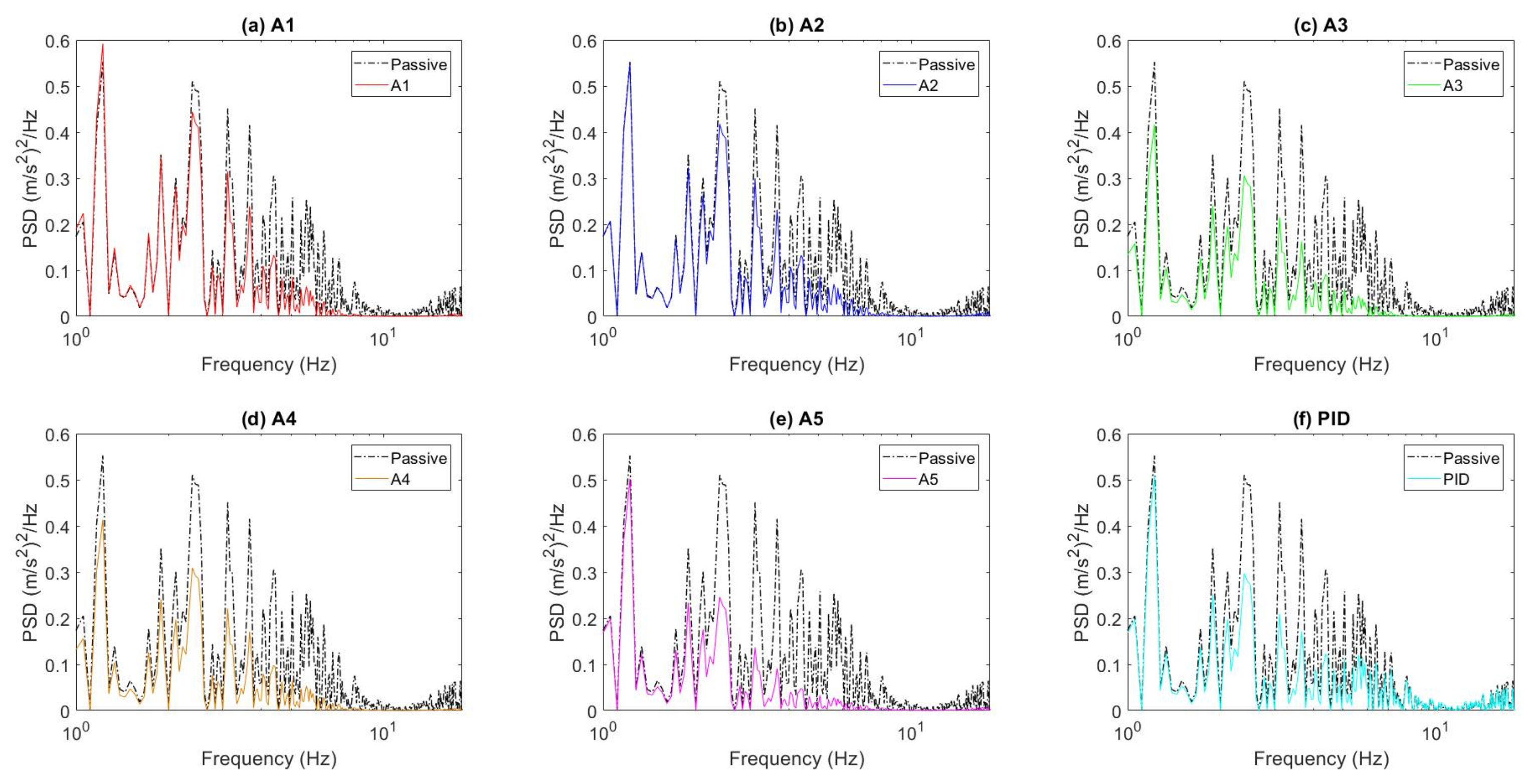
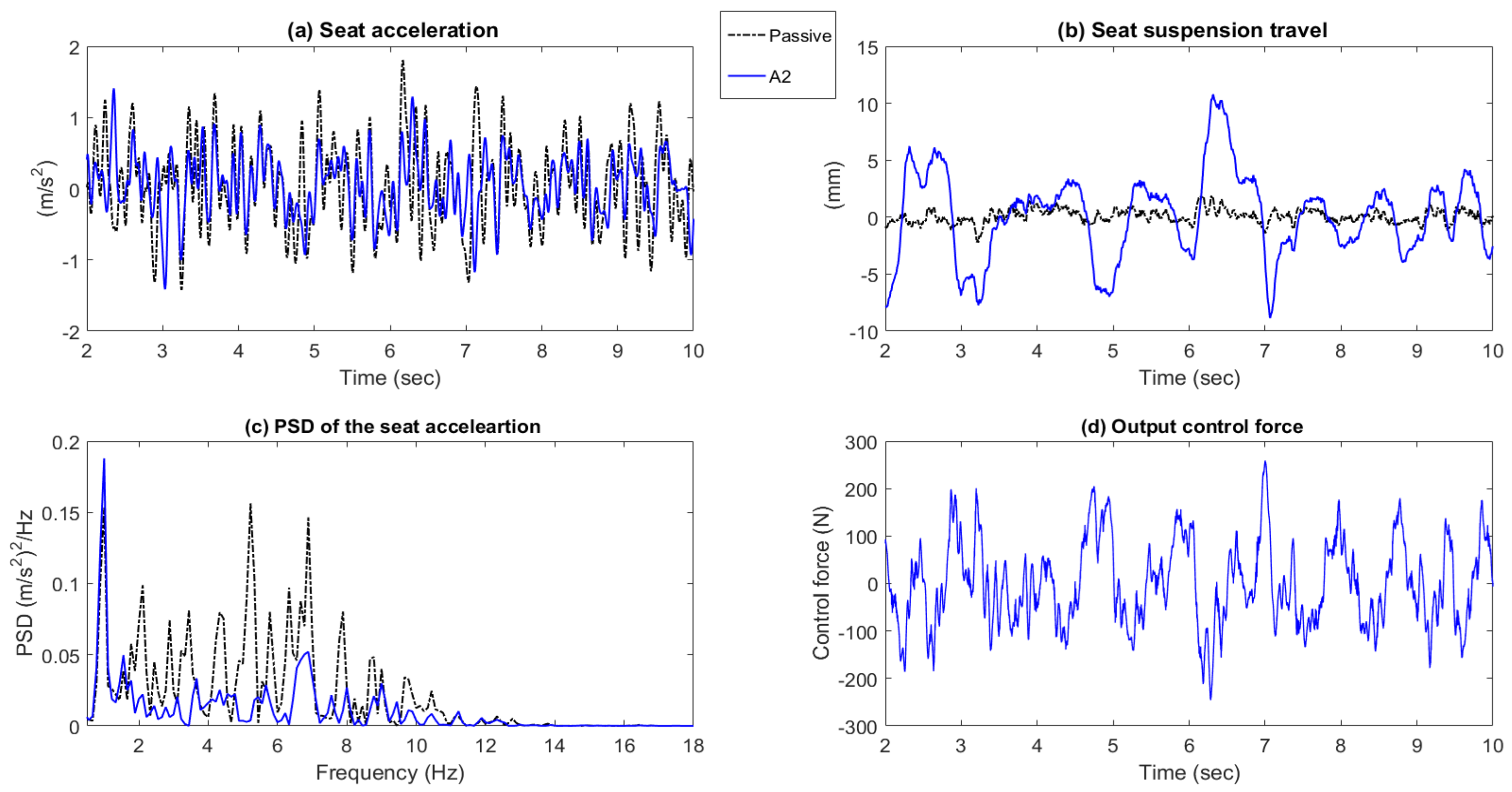
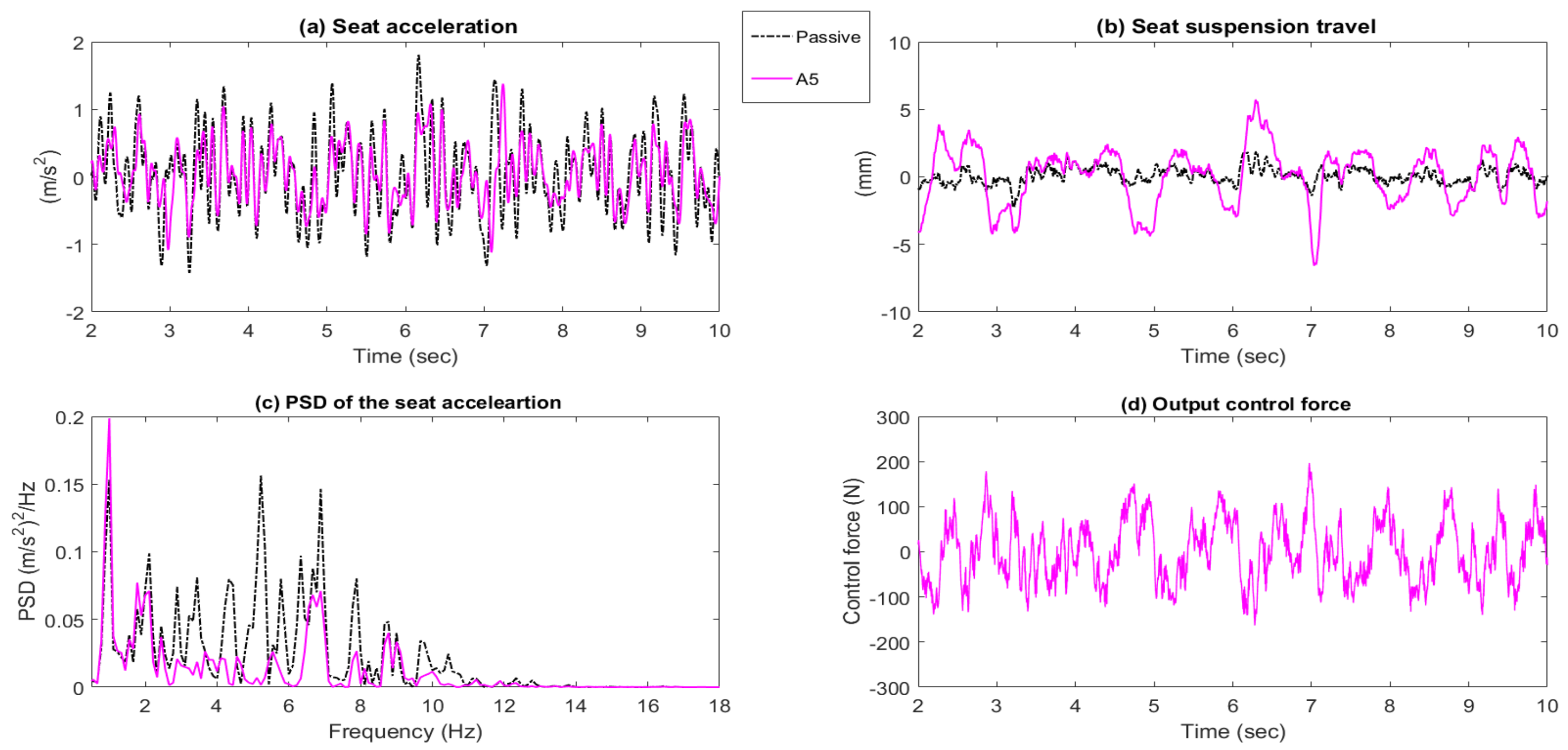
The measured seat acceleration and seat suspension travel time responses of the active seat suspension with the proposed controllers (A1 to A5), as well as the demand control force are shown in Figure 14, Figure 15, Figure 16, Figure 17 and Figure 18 parts (a), (b), and (d). It can be clearly observed that all of the proposed controllers perform better than the passive suspension in reducing the seat vertical acceleration with a reasonable seat suspension travel and demand control force. Moreover, the power spectrum densities (PSD) of the active seat suspension using the different proposed controllers (A1 to A5) are compared with the passive seat suspension in Figure 14c, Figure 15c, Figure 16c, Figure 17c and Figure 18c. Generally, the active seat suspension utilising any of these proposed controllers has lower PSD when compared with the passive system over a wide frequency range, especially in the range of 4–8 Hz where humans are most sensitive. However, at a low frequency below 4 Hz, the active seat suspension performs less well, especially controllers A1 and A2 that only use the vehicle suspension feedforward signals.
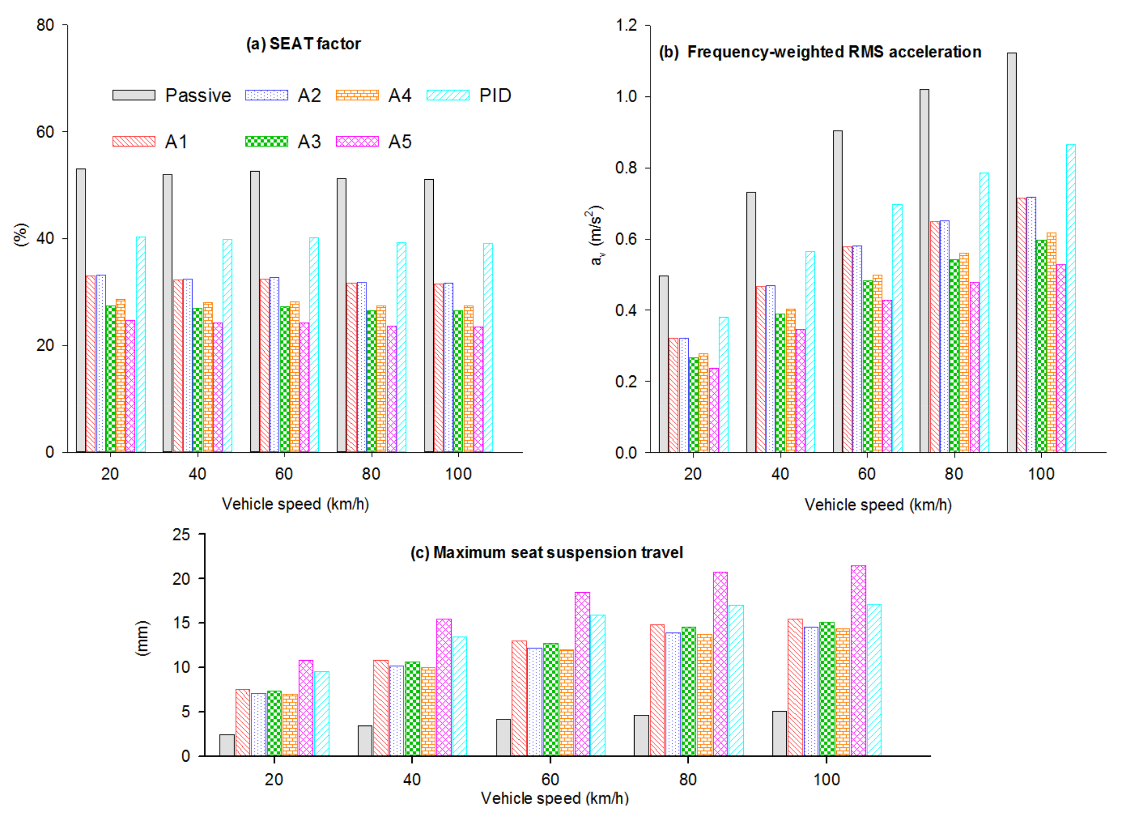
The SEAT factors of the passive and active seat suspensions at a range of vehicle speeds are shown in Figure 19. It can be clearly seen that all the proposed active controllers have SEAT factor values less than the passive, regardless of the vehicle speed. Specifically, the active seat, when using controller A4, provides the best improvement in the SEAT factor, followed by the controller A3, with a percentage improvement of at least 25% at all vehicle speeds, when compared with the passive system.
The frequency-weighted RMS seat acceleration is also presented in Figure 19. It is notable that all the proposed active seat suspension controllers provide superior lower frequency-weighted RMS seat acceleration when compared with the passive seat suspension, across the range of vehicle speeds. In addition, at intermediate and high vehicle speeds the passive seat system exceeds the “not uncomfortable” range in terms of ride comfort level according to Table 2. In summary, these results prove the capability and the robustness of the active seat suspensions using the controllers A4 and A3.
Figure 20 presents the frequency-weighted RMS acceleration of the active and passive seat suspensions with respect to the daily threshold limit values (TLVs), as suggested by ISO-2361-1, over the range of vehicle speeds. It can be seen that the active seat suspension, employing any of the proposed controllers, performs better than the passive system, especially over the human body sensitivity frequency range in which the passive system exceeds the 16 h working daily exposure limit. This indicates that, in a practical application, the active seat suspensions provide a less tiring and potentially safer working environment for drivers working long hours.
5.2.2. Bump Road Profile
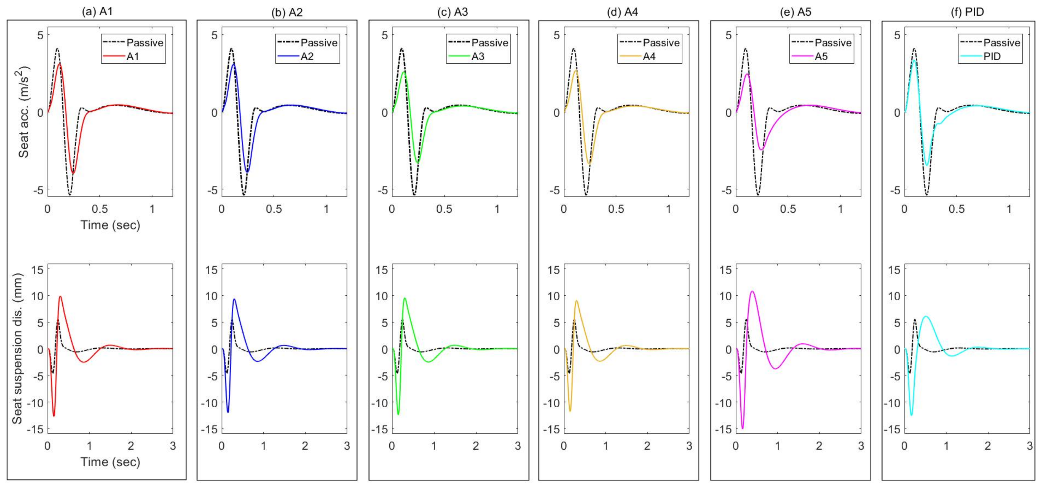
In a similar manner to the simulation analysis, the performance of the controllers was also experimentally examined when subject to a single bump road input at a vehicle speed of 25 km/h, as shown in Figure 21a. The measured time responses of the controlled active suspensions in terms of the seat acceleration and seat suspension stroke are compared with those of the passive system in Figure 21b and Figure 22. It can be seen that all the proposed active controllers effectively reduce the seat acceleration when compared with the passive system. In addition, it was observed that the controllers as well as the passive system change the static position, especially controller A1 as shown in Figure 22b. This is due to the presence of coulomb friction and results in a small random offset following each test. In summary, the controller A1 delivers the best reduction in seat acceleration followed by the controller A2 when compared with the other controllers as presented in Table 6. Although the controllers (A3 to A5) show the best performance in simulation tests, this was not backed up by the experimental results. Again, this is attributed to the effects of unmodelled higher-order system dynamics and nonlinearties.
6. Conclusions
In this paper five simple and cost-effective control strategies (A1 to A5) for an active seat suspension system have been developed in order to reduce the vertical broadband vibration (1–20 Hz) transmitted to a driver as a result of road excitation. These control strategies employ feedforward preview information from the vehicle suspension, as well as inexpensive and measurable feedback states. The performance of these controllers in attenuating the vertical seat vibration has been firstly confirmed through simulation studies using different road profiles and then validated through laboratory experimental tests using the principle of HIL testing with a physical active seat. Both the frequency and time domain performance are examined, taking into account practical constraints in both the seat suspension travel and the allowable actuator force. Both simulation and experimental results have shown that the proposed controllers effectively reduce the vertical seat acceleration over the human body sensitivity frequency range in which the experimental results show a vibration attenuation level of up to 19.5 dB when compared with a passive seat suspension. In addition, an improvement in both the SEAT factor and the weighted RMS seat acceleration of at least 25% was accomplished by the controllers A3 and A4 at the full range of vehicle speeds. Based on the experimental results, controller A4 using both feed forward suspension states and easily-measured feedback seat and vehicle chassis states provides the best performance. Furthermore, it represents a practical system that improves ride comfort and reduces the potential danger of long-term health damage for vehicle drivers.
Acknowledgments
This work is supported by the University of Bath. The technical support provided by Vijay Rajput, Martin Goater, and Graham Rattley of the Centre for Power Transmission and Motion Control (CPTMC) is greatly appreciated.
Author Contributions
This work undertaken by Abdulaziz Alfadhli as a part of his PhD study, supervised by Jocelyn Darling and Andrew J. Hillis who initially conceived and designed the project. Abdulaziz Alfadhli developed the simulation model and performed the experimental tests. All three researchers analysed the results and later wrote the paper.
Conflicts of Interest
The authors declare no conflict of interest.
| Notation | |
| Ai | i-th controller strategy |
| DOFs | Degrees of freedom |
| GA | Genetic algorithm |
| HIL | Hardware-in-the-loop simulation |
| MAST | Multi-axis simulation table |
| PSD | Power spectral density function |
| QvM | Quarter vehicle model |
| SEAT | Seat Effective Amplitude Transmissibility factor |
| TLVs | Daily threshold limit values |
| Symbol Description | |
| Total frequency-weighted RMS acceleration | |
| Frequency-weighted acceleration | |
| Frequency-weighting filter | |
| Damping coefficient of the driver’s body | |
| Damping coefficient of the vehicle suspension | |
| Damping coefficient of the seat suspension | |
| Optimization objective function | |
| Actuator control force | |
| Passive seat suspension force | |
| Seat stroke constraints | |
| Actuator capacity force constraints | |
| Estimated dynamics of the MAST | |
| Final optimization objective function | |
| Stiffness of the driver’s body | |
| Stiffness of the vehicle suspension | |
| Stiffness of the seat suspension | |
| Stiffness of the tyre | |
| Driver body mass | |
| Sprung mass in the qvm | |
| Total mass of the seat and driver | |
| Unsprung mass in the qvm | |
| Penalty function | |
| Forward speed of the vehicle | |
| Vertical road excitation to the qvm | |
| Relative displacement of the vehicle suspension | |
| Vertical displacement of the sprung mass | |
| Maximum allowable seat stroke | |
| Minimum allowable seat stroke | |
| Vertical displacement of the seat | |
| Vertical displacement of the unsprung mass | |
| Weighted root mean square of the vertical sprung mass acceleration | |
| Weighted root mean square of the vertical seat acceleration | |
| Maximum seat stroke | |
| Minimum seat stroke | |
| Relative velocity of the vehicle suspension | |
| Vertical acceleration of the sprung mass | |
| Vertical acceleration of the seat | |
| Vertical acceleration of the unsprung mass | |
References
- Griffin, M.J. Handbook of Human Vibration; Elsevier: Amsterdam, The Netherlands, 1996. [Google Scholar]
- Hiemenz, G.J.; Hu, W.; Wereley, N.M. Semi-active magnetorheological helicopter crew seat suspension for vibration isolation. J. Aircr. 2008, 45, 945–953. [Google Scholar] [CrossRef]
- Choi, S.B.; Choi, J.H.; Lee, Y.S.; Han, M.S. Vibration control of an ER seat suspension for a commercial vehicle. J. Dyn. Syst. Meas. Control 2003, 125, 60–68. [Google Scholar] [CrossRef]
- Karnopp, D. Active and semi-active vibration isolation. Trans. ASME J. Vib. Acoust. 1995, 117, 177–185. [Google Scholar] [CrossRef]
- Takács, G.; Rohal’-Ilkiv, B. Model Predictive Vibration Control: Efficient Constrained MPC Vibration Control for Lightly Damped Mechanical Structures; Springer Science & Business Media: Berlin/Heidelberg, Germany, 2012. [Google Scholar]
- Kawana, M.; Shimogo, T. Active suspension of truck seat. Shock Vib. 1998, 5, 35–41. [Google Scholar] [CrossRef]
- Gu, Z.; Zhao, Y.; Gu, Z.; Fei, S.; Tian, E. Robust control of automotive active seat-suspension system subject to actuator saturation. J. Dyn. Syst. Meas. Control Trans. ASME 2014, 136, 041022. [Google Scholar] [CrossRef]
- Stein, G.J. New results on an electropneumatic active seat suspension system. Proc. Inst. Mech. Eng. Part J. Automob. Eng. 2000, 214, 533–544. [Google Scholar] [CrossRef]
- Sun, W.; Li, J.; Zhao, Y.; Gao, H. Vibration control for active seat suspension systems via dynamic output feedback with limited frequency characteristic. Mechatronics 2011, 21, 250–260. [Google Scholar] [CrossRef]
- Wu, J.-D.; Chen, R.-J. Application of an active controller for reducing small-amplitude vertical vibration in a vehicle seat. J. Sound Vib. 2004, 274, 939–951. [Google Scholar] [CrossRef]
- Maciejewski, I.; Meyer, L.; Krzyzynski, T. The vibration damping effectiveness of an active seat suspension system and its robustness to varying mass loading. J. Sound Vib. 2010, 329, 3898–3914. [Google Scholar] [CrossRef]
- Ning, D.; Sun, S.; Li, H.; Du, H.; Li, W. Active control of an innovative seat suspension system with acceleration measurement based friction estimation. J. Sound Vib. 2016, 384, 28–44. [Google Scholar] [CrossRef]
- Ning, D.; Sun, S.; Zhang, F.; Du, H.; Li, W.; Zhang, B. Disturbance observer based Takagi-Sugeno fuzzy control for an active seat suspension. Mech. Syst. Signal Process. 2017, 93, 515–530. [Google Scholar] [CrossRef]
- Gan, Z.; Hillis, A.J.; Darling, J. Adaptive control of an active seat for occupant vibration reduction. J. Sound Vib. 2015, 349, 39–55. [Google Scholar] [CrossRef] [Green Version]
- Avdagic, Z.; Besic, I.; Buza, E.; Omanovic, S. Comparation of controllers based on Fuzzy Logic and Artificial Neural Networks for reducing vibration of the driver’s seat. In Proceedings of the 2013 39th Annual Conference of the IEEE, Vienna, Austria, 10–13 November 2013; pp. 3382–3387. [Google Scholar]
- Song, B.-K.; An, J.-H.; Choi, S.-B. A New Fuzzy Sliding Mode Controller with a Disturbance Estimator for Robust Vibration Control of a Semi-Active Vehicle Suspension System. Appl. Sci. 2017, 7, 1053. [Google Scholar] [CrossRef]
- Thong, Y.K.; Woolfson, M.S.; Crowe, J.A.; Hayes-Gill, B.R.; Jones, D.A. Numerical double integration of acceleration measurements in noise. Measurement 2004, 36, 73–92. [Google Scholar] [CrossRef]
- Fuller, C.C.; Elliott, S.; Nelson, P.A. Active Control of Vibration; Academic Press: Cambridge, MA, USA, 1996. [Google Scholar]
- Bender, E.K. Optimum linear preview control with application to vehicle suspension. J. Basic Eng. 1968, 90, 213–221. [Google Scholar] [CrossRef]
- Arunachalam, K.; Jawahar, P.M.; Tamilporai, P. Active Suspension System with Preview Control-A Review; SAE Technical Paper; SAE International: Warrendale, PA, USA, 2003. [Google Scholar]
- Sarami, S. Development and Evaluation of a Semi-Active Suspension System for Full Suspension Tractors, TU, Fachbereich Konstruktion von Maschinensystemen. 2009. Available online: https://opus4.kobv.de/opus4-tuberlin/files/2402/sarami_shahriar.pdf (accessed on 22 September 2017).
- Alfadhli, A.; Darling, J.; Hillis, A.J. The control of an active seat with vehicle suspension preview information. J. Vib. Control 2017. [Google Scholar] [CrossRef]
- Alfadhli, A.; Darling, J.; Hillis, A.J. The Control of an Active Seat Suspension Using an Optimised Fuzzy Logic Controller, Based on Preview Information from a Full Vehicle Model. Vibration 2018, 1, 3. [Google Scholar] [CrossRef]
- Dong, X.; Yu, M.; Liao, C.; Chen, W. Comparative research on semi-active control strategies for magneto-rheological suspension. Nonlinear Dyn. 2010, 59, 433–453. [Google Scholar] [CrossRef]
- Du, H.; Lam, J.; Sze, K.Y. Non-fragile output feedback H∞ vehicle suspension control using genetic algorithm. Eng. Appl. Artif. Intell. 2003, 16, 667–680. [Google Scholar] [CrossRef]
- Li, P.; Lam, J.; Cheung, K.C. Multi-objective control for active vehicle suspension with wheelbase preview. J. Sound Vib. 2014, 333, 5269–5282. [Google Scholar] [CrossRef]
- Baumal, A.E.; McPhee, J.J.; Calamai, P.H. Application of genetic algorithms to the design optimization of an active vehicle suspension system. Comput. Methods Appl. Mech. Eng. 1998, 163, 87–94. [Google Scholar] [CrossRef]
- Wang, Y.H.; Shih, M.C. Design of a genetic-algorithm-based self-tuning sliding fuzzy controller for an active suspension system. Proc. Inst. Mech. Eng. Part J. Syst. Control Eng. 2011, 225, 367–383. [Google Scholar] [CrossRef]
- Maciejewski, I.; Meyer, L.; Krzyzynski, T. Modelling and multi-criteria optimisation of passive seat suspension vibro-isolating properties. J. Sound Vib. 2009, 324, 520–538. [Google Scholar] [CrossRef]
- Tyan, F.; Hong, Y.-F.; Tu, S.-H.; Jeng, W.S. Generation of random road profiles. J. Adv. Eng. 2009, 4, 1373–1378. [Google Scholar]
- Gad, S.; Metered, H.; Bassuiny, A.; Ghany, A.A. Multi-objective genetic algorithm fractional-order PID controller for semi-active magnetorheologically damped seat suspension. J. Vib. Control. 2015, 1248–1266. [Google Scholar] [CrossRef]
- Chen, Y.; Wickramasinghe, V.; Zimcik, D. Development and evaluation of hybrid seat cushions for helicopter aircrew vibration mitigation. J. Intell. Mater. Syst. Struct. 2015, 26, 1633–1645. [Google Scholar] [CrossRef]
- Du, H.; Li, W.; Zhang, N. Integrated seat and suspension control for a quarter car with driver model. IEEE Trans. Veh. Technol. 2012, 61, 3893–3908. [Google Scholar]
- Alfadhli, A.E.H.E.; Darling, J.; Hillis, A.J. Hardware-in-the-Loop (HIL) Simulation of a Quarter Vehicle Model using a Multi-axis Simulation Table (MAST). In Proceedings of the BATH/ASME 2016 Symposium on Fluid Power and Motion Control, Bath, UK, 7–9 September 2016. [Google Scholar]
Figure 1.
Vehicle, seat, and driver physical model.

Figure 2.
Measured and simulated acceleration transmissibility of the passive seat.

Figure 3.
Simulated frequency responses of the passive and active seat suspensions.

Figure 4.
Simulated seat acceleration of the passive and active seat suspensions at a vehicle speed of 60 km/h. (a) A1; (b) A2; (c) A3; (d) A4; (e) A5; (f) PID.
Figure 4.
Simulated seat acceleration of the passive and active seat suspensions at a vehicle speed of 60 km/h. (a) A1; (b) A2; (c) A3; (d) A4; (e) A5; (f) PID.

Figure 5.
Simulated seat suspension travel of the passive and active seat suspensions at a vehicle speed of 60 km/h. (a) A1; (b) A2; (c) A3; (d) A4; (e) A5; (f) PID.
Figure 5.
Simulated seat suspension travel of the passive and active seat suspensions at a vehicle speed of 60 km/h. (a) A1; (b) A2; (c) A3; (d) A4; (e) A5; (f) PID.

Figure 6.
PSD of the seat acceleration for passive and active seat suspensions at a vehicle speed of 60 km/h. (a) A1; (b) A2; (c) A3; (d) A4; (e) A5; (f) PID.
Figure 6.
PSD of the seat acceleration for passive and active seat suspensions at a vehicle speed of 60 km/h. (a) A1; (b) A2; (c) A3; (d) A4; (e) A5; (f) PID.

Figure 7.
Simulated performance assessment of the proposed active seat suspension under different vehicle speeds. (a) SEAT factor; (b) Frequency-weighted RMS acceleration; (c) Maximum seat suspension factor.
Figure 7.
Simulated performance assessment of the proposed active seat suspension under different vehicle speeds. (a) SEAT factor; (b) Frequency-weighted RMS acceleration; (c) Maximum seat suspension factor.

Figure 8.
Simulated seat suspension acceleration of the passive and active systems when subject to a bump road input. (a) Road profile; (b) Seat acceleration.
Figure 8.
Simulated seat suspension acceleration of the passive and active systems when subject to a bump road input. (a) Road profile; (b) Seat acceleration.

Figure 9.
Simulated seat suspension performance of the passive and active systems when subject to a bump road input. (a) A1; (b) A2; (c) A3; (d) A4; (e) A5; (f) PID.
Figure 9.
Simulated seat suspension performance of the passive and active systems when subject to a bump road input. (a) A1; (b) A2; (c) A3; (d) A4; (e) A5; (f) PID.

Figure 10.
General experimental setup and HIL simulation of the proposed controllers. Thick Blue (active control force); Black (feedforward states); Red (Feedback states).
Figure 10.
General experimental setup and HIL simulation of the proposed controllers. Thick Blue (active control force); Black (feedforward states); Red (Feedback states).

Figure 11.
Schematic diagram of the active seat suspension. Reproduced with permission from [14], Elsevier, 2015.
Figure 11.
Schematic diagram of the active seat suspension. Reproduced with permission from [14], Elsevier, 2015.

Figure 12.
Measured seat acceleration transmissibilities of the passive and active systems.

Figure 13.
Random road profile at a vehicle speed of 60 km/h.

Figure 14.
Time responses and PSD of the passive system and active seat suspension with controller A1. (a) Seat acceleration; (b) Seat suspension travel; (c) PSD of the seat acceleration; (d) Output control force.
Figure 14.
Time responses and PSD of the passive system and active seat suspension with controller A1. (a) Seat acceleration; (b) Seat suspension travel; (c) PSD of the seat acceleration; (d) Output control force.

Figure 15.
Time responses and PSD of the passive system and active seat suspension with controller A2. (a) Seat acceleration; (b) Seat suspension travel; (c) PSD of the seat acceleration; (d) Output control force.
Figure 15.
Time responses and PSD of the passive system and active seat suspension with controller A2. (a) Seat acceleration; (b) Seat suspension travel; (c) PSD of the seat acceleration; (d) Output control force.

Figure 16.
Time responses and PSD of the passive system and active seat suspension with controller A3. (a) Seat acceleration; (b) Seat suspension travel; (c) PSD of the seat acceleration; (d) Output control force.
Figure 16.
Time responses and PSD of the passive system and active seat suspension with controller A3. (a) Seat acceleration; (b) Seat suspension travel; (c) PSD of the seat acceleration; (d) Output control force.

Figure 17.
Time responses and PSD of the passive system and active seat suspension with controller A4. (a) Seat acceleration; (b) Seat suspension travel; (c) PSD of the seat acceleration; (d) Output control force.
Figure 17.
Time responses and PSD of the passive system and active seat suspension with controller A4. (a) Seat acceleration; (b) Seat suspension travel; (c) PSD of the seat acceleration; (d) Output control force.

Figure 18.
Time responses and PSD of the passive system and active seat suspension with controller A5. (a) Seat acceleration; (b) Seat suspension travel; (c) PSD of the seat acceleration; (d) Output control force.
Figure 18.
Time responses and PSD of the passive system and active seat suspension with controller A5. (a) Seat acceleration; (b) Seat suspension travel; (c) PSD of the seat acceleration; (d) Output control force.

Figure 19.
Performance assessment of the proposed active seat suspensions under different vehicle speeds. (a,b) SEAT factor and percentage improvements, respectively ; (c,d) Frequency-weighted RMS seat acceleration and percentage improvements.
Figure 19.
Performance assessment of the proposed active seat suspensions under different vehicle speeds. (a,b) SEAT factor and percentage improvements, respectively ; (c,d) Frequency-weighted RMS seat acceleration and percentage improvements.

Figure 20.
Health risk assessment, according to ISO 2361-1, of the proposed active seat suspensions and passive system under different vehicle speeds (km/h). (a) 40; (b) 60; (c) 80; (d) 100.
Figure 20.
Health risk assessment, according to ISO 2361-1, of the proposed active seat suspensions and passive system under different vehicle speeds (km/h). (a) 40; (b) 60; (c) 80; (d) 100.

Figure 21.
Bump road profile and measured seat acceleration of active system using different control strategies. (a) Road profile; (b) Seat acceleration.
Figure 21.
Bump road profile and measured seat acceleration of active system using different control strategies. (a) Road profile; (b) Seat acceleration.

Figure 22.
Measured time responses of the passive and active seat suspensions when subject to a bump road input. (a) A1; (b) A2; (c) A3; (d) A4; (e) A5.
Figure 22.
Measured time responses of the passive and active seat suspensions when subject to a bump road input. (a) A1; (b) A2; (c) A3; (d) A4; (e) A5.


Table 1.
Actuator force controller algorithms.
| Control Strategy | Control Force (Fa) |
|---|---|
| A1 | |
| A2 | |
| A3 | |
| A4 | |
| A5 |
Table 2.
Vibration magnitude comfort levels (ISO 2631-1).
| Level of Comfort | Frequency-Weighted RMS Acceleration (m/s2) Range |
|---|---|
| Extremely uncomfortable | >2.0 |
| Very uncomfortable | 1.25–2.5 |
| Uncomfortable | 0.8–1.6 |
| Fairly uncomfortable | 0.5–1.0 |
| A little uncomfortable | 0.315–0.63 |
| Not uncomfortable | <0.315 |
Table 3.
QvM and estimated parameters of the passive seat suspension and the dummy.
| Parameter | Value | Unit |
|---|---|---|
| 250 | Kg | |
| 20 | Kg | |
| 1.500 | kN·s/m | |
| 10 | kN/m | |
| 180 | KN/m | |
| 5 | Kg | |
| 55.25 | Kg | |
| 2.10 | kN·s/m | |
| 42.0 | kN/m | |
| 0.9 | kN·s/m | |
| 280.0 | kN/m |
Table 4.
GA parameters.
| No. of Population | 40 |
|---|---|
| No. of generation | 1000 |
| Crossover probability | 0.2 |
| Mutation probability | 0.01 |
Table 5.
Optimum gains of active seat suspension controller strategies.
| Gain | Value | Unit |
|---|---|---|
| −64.0 | N·s/m | |
| 11.5 | kN/m | |
| −57.0 | N·s/m | |
| 10.6 | kN/m | |
| −71.0 | N·s/m | |
| 11.5 | kN/m | |
| −57.9 | N·s/m | |
| 10.6 | kN/m | |
| −43.0 | N·s/m | |
| 12.2 | kN/m | |
| 0.64 | N·s2/m | |
| 4.0 | N·s2/m | |
| 0.68 | N·s2/m | |
| 3.0 | N·s2/m | |
| −588.0 | N·s/m | |
| 19.0 | kN/m |
Table 6.
Time response characteristics of the proposed controllers under a bump road profile.
| Seat System | Seat Acceleration RMS (m/s2) | Maximum Seat Suspension Travel (mm) |
|---|---|---|
| Passive | 0.866 | 9.302 |
| A1 | 0.461 | 24.472 |
| A2 | 0.566 | 11.170 |
| A3 | 0.630 | 14.038 |
| A4 | 0.658 | 12.132 |
| A5 | 0.593 | 10.993 |
© 2018 by the authors. Licensee MDPI, Basel, Switzerland. This article is an open access article distributed under the terms and conditions of the Creative Commons Attribution (CC BY) license (http://creativecommons.org/licenses/by/4.0/).
Share and Cite
MDPI and ACS Style
Alfadhli, A.; Darling, J.; Hillis, A.J. An Active Seat Controller with Vehicle Suspension Feedforward and Feedback States: An Experimental Study. Appl. Sci. 2018, 8, 603. https://doi.org/10.3390/app8040603
AMA Style
Alfadhli A, Darling J, Hillis AJ. An Active Seat Controller with Vehicle Suspension Feedforward and Feedback States: An Experimental Study. Applied Sciences. 2018; 8(4):603. https://doi.org/10.3390/app8040603
Chicago/Turabian StyleAlfadhli, Abdulaziz, Jocelyn Darling, and Andrew J. Hillis. 2018. "An Active Seat Controller with Vehicle Suspension Feedforward and Feedback States: An Experimental Study" Applied Sciences 8, no. 4: 603. https://doi.org/10.3390/app8040603
Note that from the first issue of 2016, this journal uses article numbers instead of page numbers. See further details here.