Interface Characteristics of Ti-Clad V–4Cr–4Ti Alloy Diffusion-Bonded Joint Produced by Hot Forging


School of Materials Science and Engineering, University of Science and Technology Beijing, Beijing 100083, China
*
Author to whom correspondence should be addressed.
Appl. Sci. 2018, 8(4), 577; https://doi.org/10.3390/app8040577
Submission received: 5 March 2018
/
Revised: 29 March 2018
/
Accepted: 3 April 2018
/
Published: 7 April 2018
(This article belongs to the Section Materials Science and Engineering)
Abstract
:Diffusion bonding of V–4Cr–4Ti alloy to pure titanium (Ti) was carried out by hot forging in the temperature range between 1150 °C and 950 °C. The microstructure and mechanical properties of the bonded joint were determined by using light optical microscopy (OM), scanning electron microscopy (SEM), energy dispersive spectroscopy (EDS), micro-hardness measurements, and shear tests. The results indicate that the sound dissimilar joint can be obtained through hot forging processes. The interface has a width of about 100 μm and can be divided into two distinctive zones: a Widmanstatten structure zone and a β-Ti phase structure zone. According to the micro-hardness distribution profile across the substrates and the interface, the largest hardness of 332 HV was measured in a narrow region between the Ti substrate and the joint, which is remarkably higher than that of the substrates (Ti of 190 HV and V–4Cr–4Ti alloy of 258 HV). The lowest hardness of only 182 HV was found in a region in the V–4Cr–4Ti substrate adjacent to the joint. The shear test showed that the joint has a bonding strength higher than 165 MPa and a fracture of the joint took place in the region with the highest hardness.
1. Introduction
The development of electrically insulating coatings is extremely important for the lithium/vanadium (Li/V) blanket of the fusion reactor [1,2]. The coatings have to possess sufficiently high resistance and stability in liquid Li in order to mitigate the magnethydrodynamic (MHD) pressure drop to an acceptable level [3]. However, only a few materials constitute possible solutions, according to previous research work [3,4,5,6], because the liquid lithium acting as a strong reducing agent can dissolve most materials, especially at elevated temperatures [6].
A number of studies have shown that aluminum nitride (AlN) is a promising candidate that has high electrical resistivity and good compatibility with liquid Li as well as excellent resistance to irradiation [7,8,9]. In addition, AlN coatings can be potentially realized by in situ formation in liquid Li [10], which favor coating fabrication on surfaces with complex geometries. For monolayer AlN coatings, through-thickness defects are easy to develop since their thickness is usually limited to only a few tens of microns [11]. The presence of the through-thickness defects may degrade the integrity and insulation properties of the coating [11,12]. The reason for this is that the V-alloy substrate absorbs nitrogen from liquid Li to form vanadium nitride (VN), which breaks the dissolution equilibrium [11]. To solve this stability issue, the development of multilayer coatings is thought to be an effective approach [13,14,15] and the “V-alloy/AlN/metal” (e.g., metal = Cr, Nb [13]) multilayer coating has been investigated. This bilayer coating with an integrated top metal layer can provide enough resistance. However, the integrity and corrosion issue of the metal layer in Li could be problematic because of the chemical interactions between the metal layer and the impurities (e.g., N, C) in lithium [16,17]. In order to overcome the weakness, the “V-alloy/Ti/AlN” bilayer coating is proposed by the authors for the first time. This coating with a Ti interlayer is aimed at enhancing the stability of AlN coating in Li and depends on the formation of a titanium nitride (TiN) reaction layer at the Ti/AlN interface using an appropriate thermal treatment [18,19,20]. The TiN layer, which is chemically stable in lithium [4,6], is expected to function as a protective layer to prevent the further invasion of lithium into the V-alloy substrate despite the possible production of any through-thickness defects in the top AlN layer.
The Ti interlayer plays an important role in combing the V-alloy and AlN coating, which is why it is of great scientific and practical value to study the interface characteristics of V-alloy/Ti interface and Ti/AlN interface for fabricating the target V-alloy/Ti/AlN coating. However, the research on the interface characteristics of V-alloy/Ti joint has not been reported so far. In this work, the V–4Cr–4Ti/Ti diffusion bonded joint was produced by hot forging and the microstructure and mechanical properties of the joint were characterized.
2. Materials and Methods
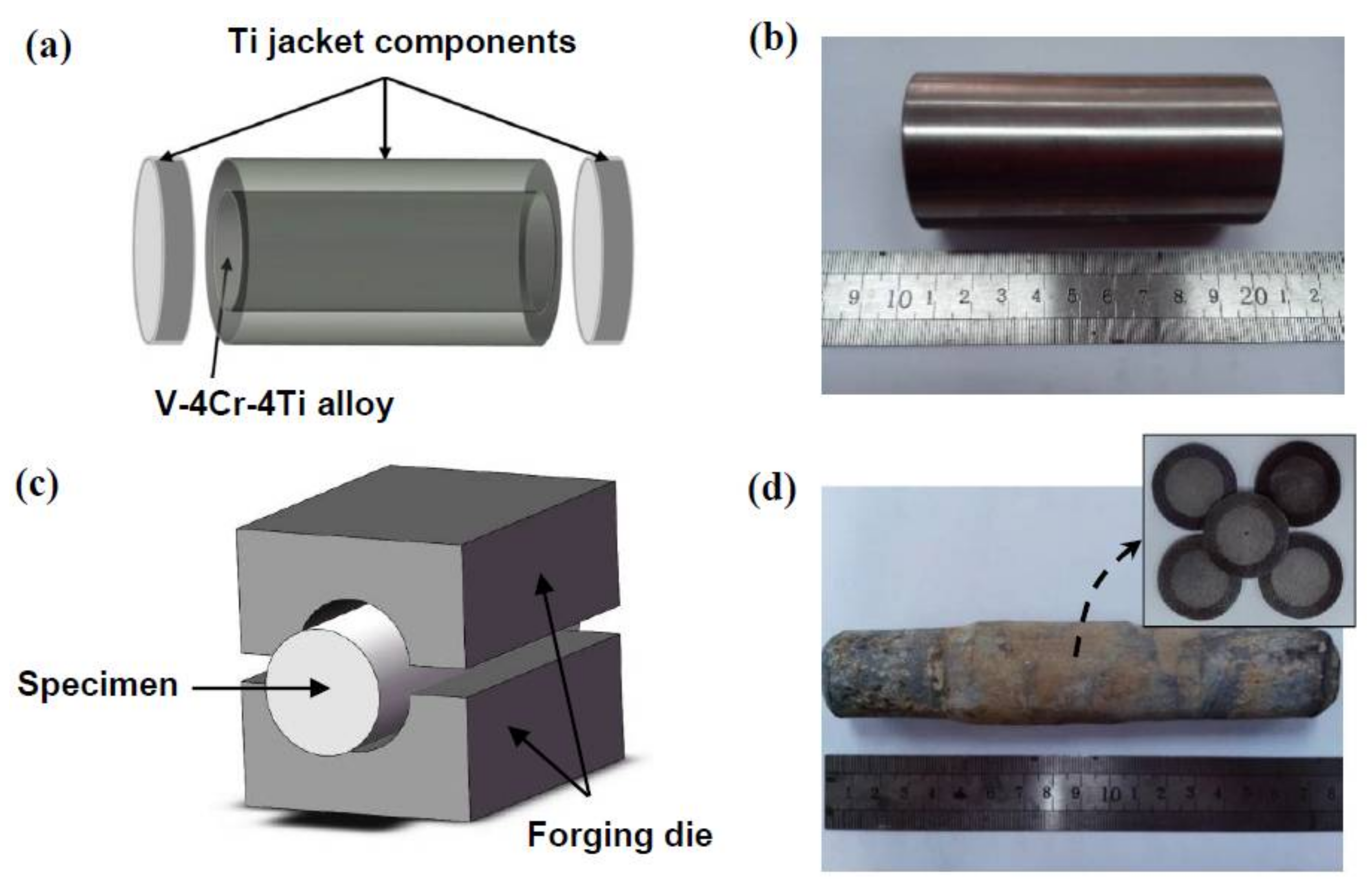
The vanadium alloy reacts readily with oxygen at elevated temperatures even in a low gas pressure environment [21]. Owing to this behavior, the alloy is usually covered with an alloy jacket (e.g., steel) to avoid oxidation during the hot processing [22]. Since we wished to study the diffusion bonding of the V–4Cr–4Ti alloy to commercially pure Ti metal, a V–4Cr–4Ti alloy rod and a Ti metal pipe as the covering jacket were employed for the bonding (see Figure 1a). The chemical compositions of the V–4Cr–4Ti alloy and the pure Ti are listed in Table 1. The V–4Cr–4Ti alloy rod was machined to a final size of 28 mm (diameter) × 75 mm (length) and then underwent turning and fine grinding. The Ti pipe was machined to be the jacket with a size of 28.2 mm (internal diameter) × 75 mm (length) × 8 mm (thickness). The V-alloy rod and Ti pipe were ultrasonically cleaned in acetone and dried prior to assembly. The two ends of the pipe were joined with pure Ti plates (44 mm in diameter × 10 mm in thickness) by electron beam welding in a vacuum. The welded specimen adopted a cylindrical geometry after hot forging and lathe turning for later bonding (see Figure 1b).
The specimen was heat treated in a furnace at 1150 °C for 2 h before the hot forging. The geometry of the forging die is illustrated in Figure 1c. The internal diameter of the die is a little smaller than the specimen in order to bond the Ti jacket to the V-alloy through a radial deformation process. Several dies with different diameters (Φ = 42 mm, 39 mm, 36mm, 33 mm, and 29 mm) were sequentially used. The forging temperature measured by a handled digital thermometer was always kept in the range between 1150 °C and 950 °C. The specimen was reheated in the furnace when cooled down to about 950 °C during the forging. Lastly, it was forged to 29 mm in diameter and then air cooled to room temperature. Cross-sections of the specimen (see Figure 1d) were sliced and mirror polished, which ensured that the specimen was ready for observation by conventional technique. The interface was etched for 10 s in an acetic solution (30 mL) of HNO (10 mL) and HF (10 mL) followed by optical microscope observation (OLYMPUS BX51M, Tokyo, Japan) to reveal the structural evolution. The joint was also examined with a scanning electron microscope (SEM, Zeiss Auriga, Germany) to observe the finer structure and determine the chemical composition distribution across the joint and the fracture surface by using energy dispersive X-ray spectroscopy (EDS, Oxford Instruments, Oxford, UK). A Vickers hardness tester (WOLPERT 430SVD, Norwood, MA, USA) with a 10 g load for 30 s was used to investigate the micro-hardness distribution across the joint.
3. Results and Discussion
Figure 2 shows the optical micrograph of the typical V–4Cr–4Ti/Ti bonded interface. It presents a smooth interface without any observable cracks. The range of the diffusion interface is approximately 100 μm wide and can be divided into two distinct zones. Zone I lies close to the Ti side and is about 70 μm in width. It features a needle-cluster structure. At the same time, zone II is about 30 μm wide and is located close to the V-alloy side, which features a uniform band structure. This interface microstructure resembles the pure Ti/steel diffusion-bonded joint [23,24,25], which is mainly attributed to the varied concentration of β-Ti stabilizers (e.g., Fe, V, or Cr) across the interface [26,27]. According to [23,24,25,26,27], zone II should be the uniform β-Ti phase band structure because of the high concentration of V (see Figure 3). Zone II is adjacent to the V-alloy substrate and is rich in V content, which favors β-Ti solid solution phase stability up to room temperature [27]. Since the β-Ti phase is difficult to etch [23], zone II appears clean without visible metallurgical structure [25]. When the concentration of the stabilizers is relatively low, it may lead to partial β→α phase transformation and form the Widmanstätten structure [26]. Zone I is located far from the V-alloy substrate and its characteristic Widmanstätten structure (α + β phases) should be attributed to the lower concentration of V and Cr (β-Ti stabilizers).
The diffusional behavior of V, Cr, and Ti across the joint was determined by EDS, which is shown in Figure 3. It is shown that the concentration of these elements change gradually across zone I while drastic changes are observed in zone II, which should act as a boundary of the interface. The EDS analysis shows that the V concentration in zone I is lower than ~16 wt % while it ranges from ~17 to 93 wt % in zone II. The Cr concentration across the interface is very low even in zone II. Since the diffusion coefficient for Cr (DCr) in V is so small (e.g., DCr = 5.84 × 10⁻¹⁷ m2/s at 1383 K [28]), the diffusion distance of Cr should be limited in the V–4Cr–4Ti alloy.
The mutual diffusion of the elements in the parent alloys promotes the formation of the V–4Cr–4Ti/Ti joint, which changed the microstructure and also the hardness. Vickers hardness measurements were performed across the substrates and the joint. According to the hardness distribution profile, six characteristic parts (A, B, C, D, E, and F) were defined (see Figure 4). Part A and F refer to the regions in Ti and V–4Cr–4Ti alloy substrates far from the bonded interface, which measures 190 HV and 258 HV, respectively. Part C corresponds to zone I and part D to zone II. Part B and E are the intermediate layers shown in Figure 4. It can be found that the highest hardness (332 HV) appeared at the boundary of part C adjacent to the Ti substrate because of the stress concentration induced by the Ti phase transformation during the cooling after the forging process. It has been shown that the appropriate post weld heat treatment (PWHT) can be effective for decreasing the hardness and increasing the toughness of some welded joints [29,30]. Therefore, the PWHT could also be adopted to recover the hardness of the V–4Cr–4Ti/Ti joint. Part E lays in the V-alloy substrate adjacent to the joint and exhibits the lowest hardness at only 180 HV. Nishimura et al. [31] reported that the typical precipitates such as Ti-CON in the V–4Cr–4Ti alloy could be decomposed at the forging temperature. Therefore, it is expected that the solid-solution hardening agents, C, O, and N, might be transferred from the V–4Cr–4Ti alloy to the Ti substrate during the forging process due to their chemical affinity. During the cooling after forging, the Ti-CON substance should be re-produced. However, its amount in part E should be less than the original one because of the loss of the interstitial impurities. Therefore, the region with less precipitate exhibits less hardness than the V-alloy substrate. In addition, the average hardness of Ti and V-alloy substrates were 190 HV and 258 HV, respectively.
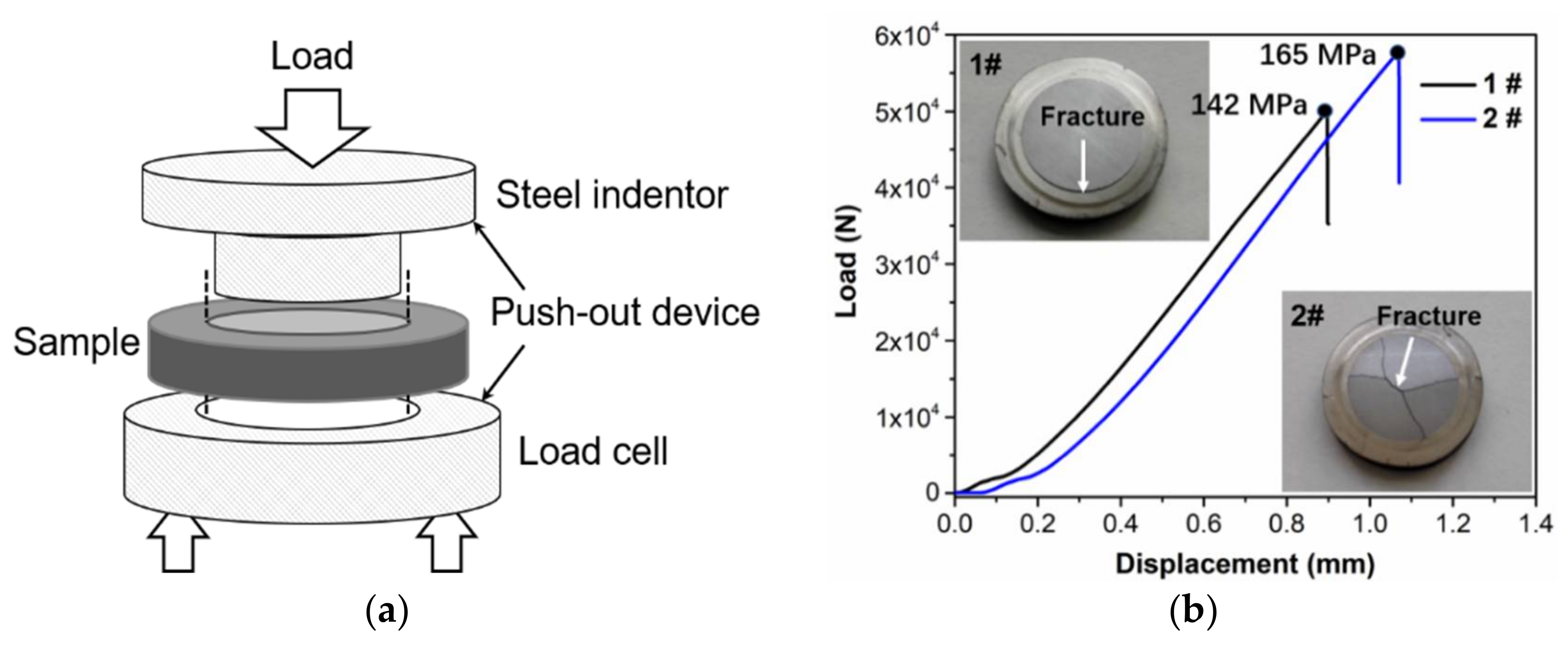
The bonding strength of the V–4Cr–4Ti/Ti joint was studied using the push-out method [32] and the schematic diagram is shown in Figure 5a. The bonding strength (τ) of the joint can be approximately calculated using the formula below.
where F is the applied maximum load, D is the diameter of the central V–4Cr–4Ti rod, and h is the disc thickness.
Two types of failure of the joint were observed during the shear tests: type one occurred around the joint (e.g., specimen 1# in Figure 5b) and type two occurred in the central V–4Cr–4Ti alloy (e.g., specimen 2# in Figure 5b). For the first type, the failure appears at a narrow region between the Ti substrate and the joint, which was confirmed by SEM (see Figure 6). This is probably ascribed to the stress concentration produced by phase transformation of Ti during the cooling process. When Ti metal is cooled from a high forging temperature (950 °C or higher) to room temperature, it transforms from the bcc structure (β-Ti) to the hcp structure (α-Ti) [33]. The dilational stress produced at the interface results in the extreme hardness. In addition, since the push-out test is terminated once the specimen has partly failed during the test, the bonding strength of the joint should be higher than the calculated value of 165 MPa (see Figure 5b).
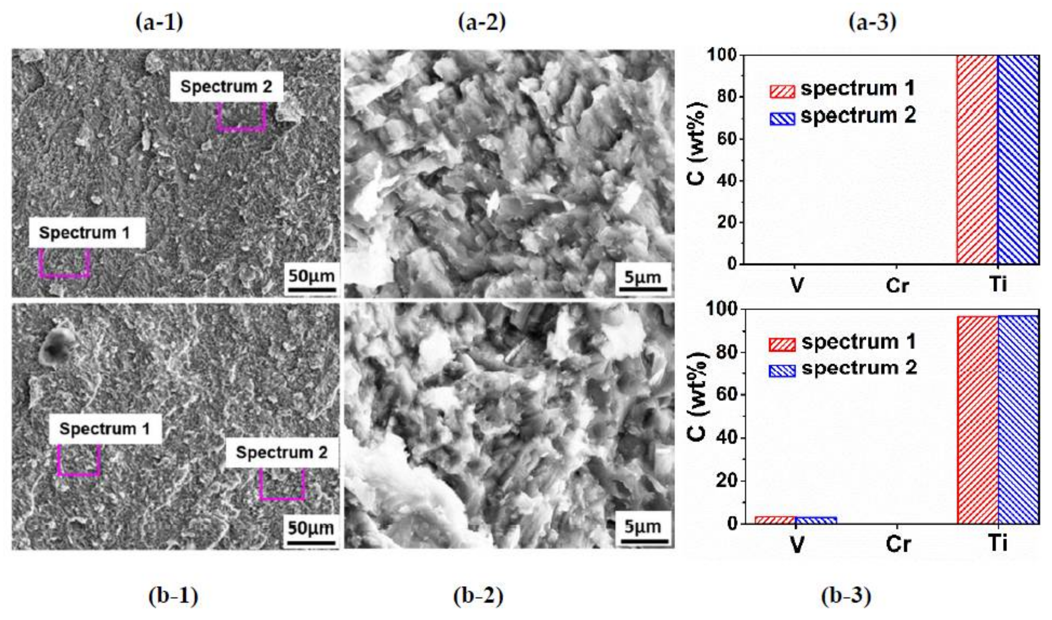
The fracture surface on the side of the V–4Cr–4Ti alloy was analyzed by using SEM and EDS. A relatively smooth fracture surface morphology was observed at low magnification, which is shown in Figure 6a-1,b-1. At higher magnification, the fracture surface had a plastic deformation during the shear punch test according to the surface microstructure, which is shown in Figure 6a-2,b-2. EDS analysis revealed that the Ti concentration of the typical fracture surfaces on the V–4Cr–4Ti alloy side was nearly 100% (see Figure 6a-3,b-3), which indicates the failure of the joint took place in a narrow region in the joint close to the Ti substrate. It was observed that the phase transformation of the Ti substrate gave rise to the extreme hardness as well as the weakness in the transitional region.
4. Conclusions
A dissimilar joint of the V–4Cr–4Ti alloy/pure Ti was successfully prepared by using the hot forging technique in the temperature range between 1150 °C and 950 °C. The microstructure and mechanical properties of the joint were studied. Based on the results, conclusions are shown below.
- (1)
- A sound diffusion-bonded interface was obtained. The interface was about 100 μm in width and can be divided into two different zones in which zone I is the Widmanstatten structure consisting of an α-Ti phase and β-Ti phase and zone II—adjacent to V–4Cr–4Ti substrate—is the single β-Ti phase band structure.
- (2)
- A maximum micro-hardness value of 332 HV was measured at the transitional region between the Ti substrate and the V–4Cr–4Ti/Ti joint while the minimum level of hardness reaching only 182 HV was located in a region in the V–4Cr–4Ti substrate adjacent to the joint. The average hardness of the Ti substrate and the V–4Cr–4Ti alloy are 190 HV and 258 HV, respectively.
- (3)
- The bonding strength of the V–4Cr–4Ti/Ti joint was higher than 165 MPa, according to the results of push-out tests. It was demonstrated that the fracture of the joint took place in the region with the highest hardness, which is probably ascribed to the stress concentration caused by the phase transformation of the Ti substrate during the air cooling process.
Acknowledgments
This research is supported by the National Magnetic Confinement Fusion Science Program of China (No. 2014GB120000), the Beijing Natural Science Foundation (No. 2182043), and the Fundamental Research Funds for the Central Universities (No. FRF-TP-16-029A1).
Author Contributions
Farong Wan conceived and designed the experiments. Gaowei Zhang performed the experiments and contributed with reagents/materials/analysis tools. Gaowei Zhang, Farong Wan, Wentuo Han, and Xiaoou Yi analyzed the data. Gaowei Zhang wrote the paper.
Conflicts of Interest
The authors declare no conflict of interest.
References
- Malang, S.; Leroy, P.; Casini, G.P.; Mattas, R.F. Crucial issues on liquid metal blanket design. Fusion Eng. Des. 1991, 16, 95–109. [Google Scholar] [CrossRef]
- Barleon, L.; Casal, V.; Lenhart, L. MHD flow in liquid-metal-cooled blankets. Fusion Eng. Des. 1991, 14, 401–412. [Google Scholar] [CrossRef]
- Malang, S.; Borgstedt, H.U.; Farnum, E.H.; Natesan, K.; Vitkovski, I.V. Development of insulating coatings for liquid metal blankets. Fusion Eng. Des. 1995, 27, 570–586. [Google Scholar] [CrossRef]
- Muroga, T.; Pint, B.A. Progress in the development of insulator coating for liquid lithium blankets. Fusion Eng. Des. 2010, 85, 1301–1306. [Google Scholar] [CrossRef]
- Pint, B.A.; Devan, J.H.; Distefano, J.R. Temperature limits on the compatibility of insulating ceramics in lithium. J. Nucl. Mater. 2002, 307–311, 1344–1350. [Google Scholar] [CrossRef]
- Hubberstey, P.; Sample, T. Thermodynamics of the interactions between liquid breeders and ceramic coating materials. J. Nucl. Mater. 1997, 248, 140–146. [Google Scholar] [CrossRef]
- Natesan, K.; Reed, C.B.; Rink, D.L.; Haglund, R.C. Development and performance of aluminum nitride insulating coatings for application in a lithium environment. J. Nucl. Mater. 1998, 258–263, 488–494. [Google Scholar] [CrossRef]
- Suzuki, A.; Muroga, T.; Pint, B.A.; Yoneoka, T.; Tanaka, S. Corrosion behaviour of AlN for self-cooled Li/V blanket application. Fusion Eng. Des. 2003, 69, 397–401. [Google Scholar] [CrossRef]
- Smith, D.L.; Konys, J.; Muroga, T.; Evitkhin, V. Development of coatings for fusion power applications. J. Nucl. Mater. 2002, 307–311, 1314–1322. [Google Scholar] [CrossRef]
- Vertkov, A.V.; Evtikhin, V.A.; Lyublinski, I.E. Self-healing electrical insulating coating processes for vanadium alloy–lithium systems. Fusion Eng. Des. 2001, 58–59, 731–735. [Google Scholar] [CrossRef]
- Pint, B.A.; Tortorelli, P.F.; Jankowski, A.; Hayes, J.; Muroga, T.; Suzuki, A.; Yeliseyeva, O.I.; Chernov, V.M. Recent progress in the development of electrically insulating coatings for a liquid lithium blanket. J. Nucl. Mater. 2004, 329–333, 119–124. [Google Scholar] [CrossRef]
- Terai, T.; Suzuki, A.; Yoneoka, T.; Mitsuyama, T. Compatibility of AlN with liquid lithium. J. Nucl. Mater. 2000, 283–287, 1322–1325. [Google Scholar] [CrossRef]
- Vitkovsky, I.V.; Gorunov, A.V.; Engelko, V.I.; Kirillov, I.R. Development and testing of electroinsulating barriers for lithium-vanadium fusion blanket. Fusion Eng. Des. 2002, 61–62, 739–743. [Google Scholar] [CrossRef]
- Pint, B.A.; Moser, J.L.; Jankowski, A.; Hayes, J. Compatibility of multi-layer, electrically insulating coatings for vanadium–lithium blankets. J. Nucl. Mater. 2007, 367–370, 1165–1169. [Google Scholar] [CrossRef]
- Pint, B.A.; Pawel, S.J.; Howell, M.; Moser, J.L.; Garner, G.W.; Santella, M.L.; TortorelliF, P.F.; Wiffen, W.; DiStefano, J.R. Initial characterization of V–4Cr–4Ti and MHD coatings exposed to flowing Li. J. Nucl. Mater. 2009, 386–388, 712–715. [Google Scholar] [CrossRef]
- Chopra, O.K.; Smith, D.L. Corrosion behavior of vanadium alloys in flowing lithium. J. Nucl. Mater. 1988, 155–157, 683–689. [Google Scholar] [CrossRef]
- Evtikhin, V.A.; Lyublinski, I.E.; Pankratov, V.Y. Vanadium alloys as structural materials for liquid lithium blanket of fusion reactors. J. Nucl. Mater. 1992, 191–194, 924–927. [Google Scholar] [CrossRef]
- Yasumoto, T.; Yamakawa, K.; Iwase, N.; Shinosawa, N. Reaction between AlN and Metal Thin Films during High Temperature Annealing. J. Cerem. Soc. Jpn. 1993, 101, 969–973. [Google Scholar] [CrossRef]
- He, X.; Yang, S.; Du, Y.; Tao, K. Reaction layer formation at the interface Ti or Zr and AlN. Phys. Stat. Sol. A 1996, 157, 99–106. [Google Scholar] [CrossRef]
- He, X.; Yang, S.; Tao, K.; Fan, G. Investigation of the interface reactions of Ti thin films with AlN substrate. J. Mater. Res. 1997, 12, 846–851. [Google Scholar] [CrossRef]
- DiStefano, J.R.; DeVan, J.H. Reactions of oxygen with V-Cr-Ti alloys. J. Nucl. Mater. 1997, 249, 150–158. [Google Scholar] [CrossRef]
- Potapenko, M.M.; Drobishev, V.A.; Filkin, V.Y.; Gubkin, I. Manufacture of semifinished items of alloys V-4Ti-4Cr and V-10Ti-5Cr for use as a structural material in fusion application. J. Nucl. Mater. 1996, 233–237, 438–441. [Google Scholar] [CrossRef]
- Bhanumurthy, K.; Kale, G.B. Reactive diffusion between titanium and stainless steel. J. Mater. Sci. Lett. 1993, 12, 1879–1881. [Google Scholar] [CrossRef]
- Kundu, S.; Ghosh, M.; Laik, A.; Bhanumurthy, K.; Kale, G.B.; Chatterjee, S. Diffusion bonding of commercially pure titanium to 304 stainless steel using copper interlayer. Mater. Sci. Eng. A 2005, 407, 154–160. [Google Scholar] [CrossRef]
- Qin, B.; Sheng, G.M.; Huang, J.W.; Zhou, B.; Qiu, S.Y.; Li, C. Phase transformation diffusion bonding of titanium alloy with stainless steel. Mater. Charact. 2006, 56, 32–38. [Google Scholar] [CrossRef]
- Sridhar, G.; Kutumbarao, V.V.; Sarma, D.S. The influence of heat treatment on the structure and properties of a near-α titanium alloy. Metall. Trans. A 1987, 18A, 877–891. [Google Scholar] [CrossRef]
- Gil, F.J.; Ginebra, M.P.; Manero, J.M.; Planell, J.A. Formation of α-Widmanstätten structure: Effects of grain size and cooling rate on the Widmanstätten morphologies and on the mechanical properties in Ti6Al4V alloy. J. Alloys Compd. 2001, 329, 142–152. [Google Scholar] [CrossRef]
- Pelleg, J. Diffusion of 51Cr in vanadium. Philos. Mag. A 1995, 71, 431–439. [Google Scholar] [CrossRef]
- Tsisar, V.; Nagasaka, T.; Flem, M.L.; Yeliseyeva, O.; Konys, J.; Muroga, T. Effect of post-weld heat treatment on microstructure, hardness and low-temperature impact toughness of electron beam welds of NIFS-HEAT-2 and CEA-J57 heats of V–4Ti–4Cr alloy. Nucl. Mater. Energy 2016, 9, 436–440. [Google Scholar] [CrossRef]
- Chennaiah, M.B.; Kumar, P.N.; Rao, K.P. Effect of PWHT on the hardness and fractured microstructure of IS-103Cr1 welded joint. Mater. Today Proc. 2017, 4, 1193–1198. [Google Scholar] [CrossRef]
- Nishimura, A.; Iwahori, A.; Heo, N.J.; Nagasaka, T.; Muroga, T.; Tanaka, S.I. Effect of precipitation and solution behavior of impurities on mechanical properties of low activation vanadium alloy. J. Nucl. Mater. 2004, 329, 438–441. [Google Scholar] [CrossRef]
- Dezellus, O.; Milani, L.; Bosselet, F.; Sacerdote-Peronnet, M.; Rouby, D.; Viala, J.-C. Mechanical testing of titanium/aluminium–silicon interfaces by push-out. J. Mater. Sci. 2008, 43, 1749–1756. [Google Scholar] [CrossRef]
- Seward, G.G.E.; Celotto, S.; Prior, D.J.; Wheeler, J.; Pond, R.C. In situ SEM-EBSD observations of the hcp to bcc phase transformation in commercially pure titanium. Acta Mater. 2004, 52, 821–832. [Google Scholar] [CrossRef]
Figure 1.
Schematic diagrams illustrating the specimen preparation and hot forging process: (a) the assembly of materials; (b) the assembled piece prior to forging; (c) the geometry of hot forging; (d) the assembled piece after forging.
Figure 1.
Schematic diagrams illustrating the specimen preparation and hot forging process: (a) the assembly of materials; (b) the assembled piece prior to forging; (c) the geometry of hot forging; (d) the assembled piece after forging.

Figure 2.
Optical micrograph of a typical V–4Cr–4Ti/Ti bonded interface.
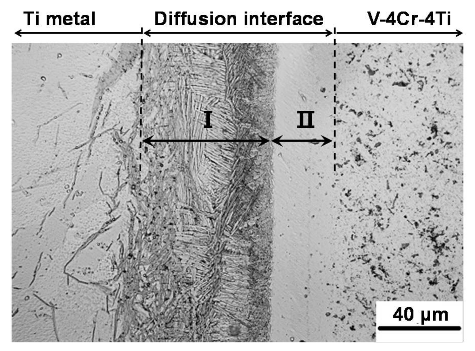
Figure 3.
Concentration profiles of Ti, V, and Cr across the chemically etched V–4Cr–4Ti/Ti joint.
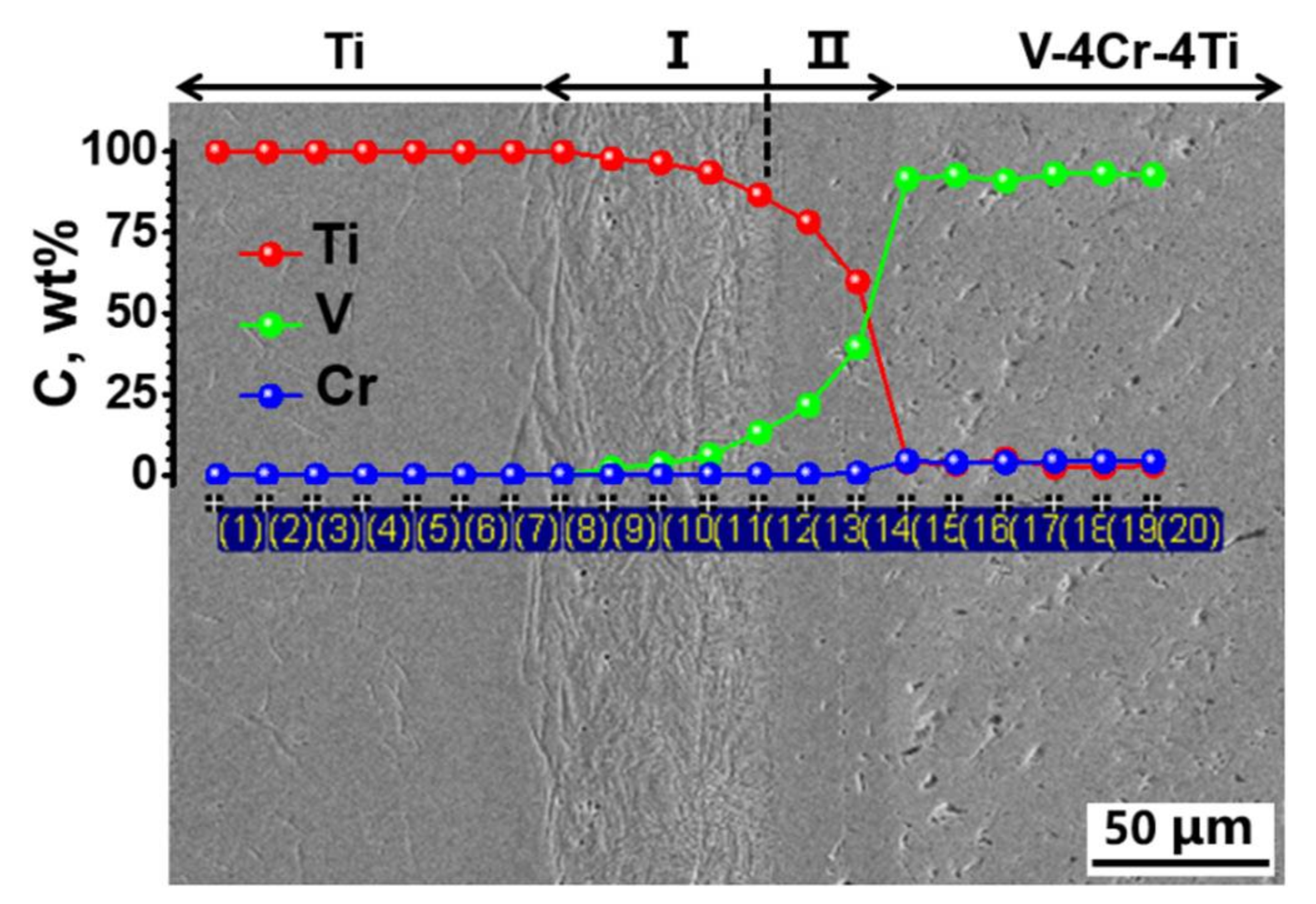
Figure 4.
Vickers-hardness distribution across the V–4Cr–4Ti/Ti joint.
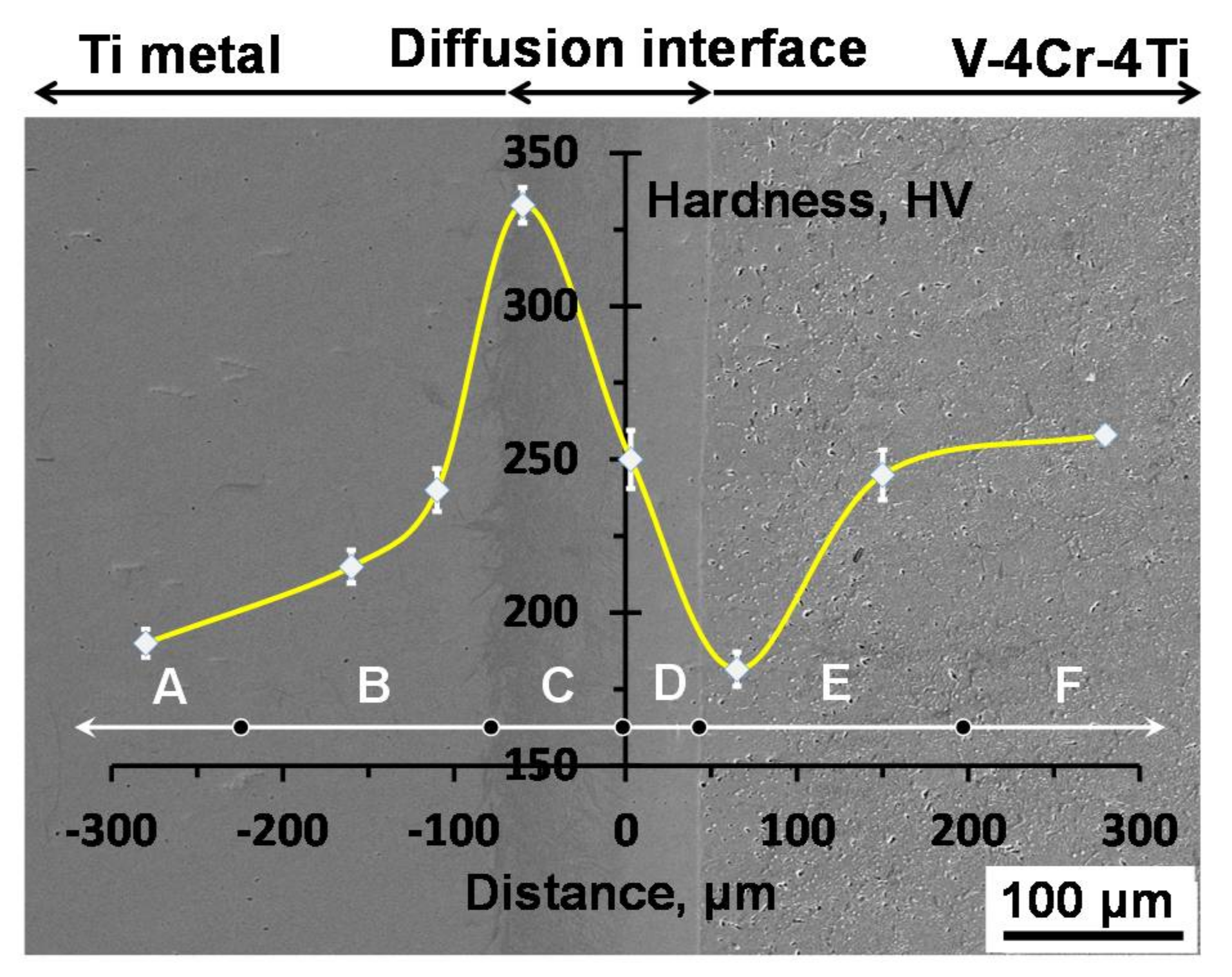
Figure 5.
Bonding strength tests: (a) schematic diagram of the apparatus; (b) load-displacement curves of the V–4Cr–4Ti/Ti joint.
Figure 5.
Bonding strength tests: (a) schematic diagram of the apparatus; (b) load-displacement curves of the V–4Cr–4Ti/Ti joint.

Figure 6.
Scanning electron microscope (SEM) micrographs and chemical analysis of the fracture surface on the V–4Cr–4Ti alloy side: (a-1,b-1) surface appearance at 1000× magnification; (a-2,b-2) surface appearance at 10,000× magnification; (a-3,b-3) chemical analysis of the selected areas in (a-1,b-1), respectively.


Table 1.
Chemical composition of the parent materials (wt %).
| Material | V | Ti | Cr | Fe | C | N | O |
|---|---|---|---|---|---|---|---|
| V–4Cr–4Ti | Bal. | 3.36 | 3.45 | - | 0.052 | 0.001 | 0.033 |
| Pure Ti | - | Bal. | - | 0.2 | 0.1 | 0.05 | 0.2 |
© 2018 by the authors. Licensee MDPI, Basel, Switzerland. This article is an open access article distributed under the terms and conditions of the Creative Commons Attribution (CC BY) license (http://creativecommons.org/licenses/by/4.0/).
Share and Cite
MDPI and ACS Style
Zhang, G.; Han, W.; Yi, X.; Wan, F. Interface Characteristics of Ti-Clad V–4Cr–4Ti Alloy Diffusion-Bonded Joint Produced by Hot Forging. Appl. Sci. 2018, 8, 577. https://doi.org/10.3390/app8040577
AMA Style
Zhang G, Han W, Yi X, Wan F. Interface Characteristics of Ti-Clad V–4Cr–4Ti Alloy Diffusion-Bonded Joint Produced by Hot Forging. Applied Sciences. 2018; 8(4):577. https://doi.org/10.3390/app8040577
Chicago/Turabian StyleZhang, Gaowei, Wentuo Han, Xiaoou Yi, and Farong Wan. 2018. "Interface Characteristics of Ti-Clad V–4Cr–4Ti Alloy Diffusion-Bonded Joint Produced by Hot Forging" Applied Sciences 8, no. 4: 577. https://doi.org/10.3390/app8040577
Note that from the first issue of 2016, this journal uses article numbers instead of page numbers. See further details here.