Fault Studies and Distance Protection of Transmission Lines Connected to DFIG-Based Wind Farms

1
Smart Grid Key Laboratory of Ministry of Education, Tianjin University, Tianjin 300072, China
2
Maintenance Company of Tianjin Electric Power Company, Tianjin 300250, China
3
Electric Power Dispatching Control Center of Guizhou Power Grid Company, Guiyang 550002, China
*
Author to whom correspondence should be addressed.
Appl. Sci. 2018, 8(4), 562; https://doi.org/10.3390/app8040562
Submission received: 12 February 2018
/
Revised: 30 March 2018
/
Accepted: 31 March 2018
/
Published: 5 April 2018
(This article belongs to the Special Issue Large Grid-Connected Wind Turbines)
Abstract
:Featured Application
The work can improve technology level of relay protection equipment and distance protection reliability of transmission lines connected to wind farms.
Abstract
Doubly fed induction generator (DFIG) based wind farms are being increasingly integrated into power grids with transmission lines, and distance protection is usually used as either the main or the backup protection for the transmission line. This paper analyzes the composition of a DFIG short circuit current and indicates the existence of a rotor speed frequency component. By analyzing several real fault cases of the DFIG-based wind farms connected to transmission lines, the weak power supply system and current frequency deviation of the wind farm side are illustrated. When a fault occurs on the transmission line, the short circuit current on the wind farm side is small and its frequency may no longer be nominal due to the existence of rotor speed frequency component, whereas the voltage frequency remains nominal frequency because of the grid support. As a result, the conventional distance protection cannot accurately measure the impedance, which can result in unnecessary circuit breaker tripping. Therefore, a time-domain distance protection method combined with the least-squares algorithm is proposed to address the problem. The efficacy of the proposed method is validated with real fault cases and simulation.
1. Introduction
In addressing the problems of environmental pollution and energy shortages, the world has been focusing on the development and use of wind energy, and large-scale wind farms are being increasingly integrated into the power grid. Wind turbines based on doubly fed induction generator (DFIG) have been widely used in existing wind farms [1,2] due to the benefits including flexible power control, high efficiency, and small converter capacity [3,4,5].
However, DFIG is sensitive to grid disturbances, especially to voltage sags. The grid voltage sags cause a large transient overcurrent in the DFIG rotor circuit [6,7]. As a result, the DFIG is disconnected from the grid to avoid damage to the rotor side converter (RSC). With the increasing popularity of wind power, the grid codes [8,9,10] require the wind farms to remain connected to power grid during grid–voltage sags to ensure system stability. Therefore, low voltage ride through (LVRT) techniques are proposed to protect the converter, meaning that the DFIG does not need to be disconnected from the grid during disturbances [11,12]. A commonly adopted solution to protect the DFIG converter during voltage sags is to use a crowbar circuit to isolate the RSC from the rotor circuit [13,14].
Many studies have been performed to investigate the DFIG fault characteristics considering LVRT capability. Due to the influence of power electronic devices, the DFIG fault characteristics are different from the traditional synchronous generator. The behavior of the DFIG during three-phase voltage sags was analyzed [15]. The authors divided the magnetic flux of the machine into forced flux and natural flux to help understand the causes of the overcurrent that appear during a fault. The physical behavior of the DFIG was presented and later developed with analytical solutions for the generalized DFIG equations operating under symmetrical fault conditions [16]. Comparing the conventional induction machine with DFIG, the short-circuit current expression of a crowbar-protected DFIG and the maximum value of the short-circuit current were outlined [17,18]. The DFIG operation under asymmetrical voltage sags and why such sags are more harmful than symmetrical sags were explained [19]. In addition, the DFIG fault current characteristics under non-severe fault conditions were studied [20,21,22]. Under non-severe faults, the crowbar protection is not activated and the DFIG fault current characteristics are considerably different than that under severe fault conditions. Notably, the fault characteristics of DFIG with LVRT capability are influenced by the control strategy. A detailed analysis was completed by considering the influence of the controller on short-circuit parameters, such as time constants, initial symmetrical short-circuit current, and the peak short-circuit current [23]. Hence, many researchers have attempted to improve the DFIG control strategy to meet the grid code requirements [24,25,26].
DFIG pose new problems and challenges for the traditional relaying protection of the power grid. Although the aforementioned DFIG fault characteristics have been scrutinized in many publications, the negative impacts of DFIG on the protection of the transmission system, and particularly distance protection, have not received sufficient attention. Large-scale DFIG-based wind farms are generally integrated into power grids with transmission lines, and distance protection is usually used as either the main or the backup protection for the transmission line [27]. Refs. [28,29] indicated that traditional distance protection and directional elements are unreliable when a balanced fault occurs because the fault current frequency of DFIG significantly deviates from the nominal frequency. The impacts of grounding configurations on ground protective devices used in DFIG-based wind energy conversion systems were studied in [30,31]. However, fault characteristics of DFIG-based wind farms and the performance of distance protection when unbalanced faults occur on high voltage transmission lines should be further studied.
According to analyses in the literature [17,18,19], the DFIG short-circuit current involves a transient alternating current (AC) component decay at near rotor frequency. As a result, the conventional distance protection based on nominal frequency may fail to measure the correct impedance. To fill the gap, this paper analyzes real fault cases where unbalanced faults occurred at the transmission lines connected to DFIG-based wind farms in China. The fault characteristics and distance protection applicability of the transmission lines connected to DFIG-based wind farms are obtained. Furthermore, a time-domain distance protection method combined with the least-squares algorithm is proposed. The proposed method can overcome the influence of frequency variation as a result that fault distances can be identified accurately and quickly when faults occur on the transmission line connected to a DFIG-based wind farm. With the help of the proposed method, Relay Protection Equipment Manufacturers can improve the equipment level of technology, and the grid companies can improve the safe operation level of power system.
The rest of this work is structured as follows. Section 2 illustrates the composition of DFIG short circuit current and fault characteristics of DFIG-based wind farms connected to transmission lines. Section 3 analyzes the distance protection applicability, and a time-domain distance protection method is proposed for the transmission lines connected to DFIG-based wind farms. The reliability and correctness of the method are validated through real fault cases and simulation tests. Section 4 presents the conclusions.
2. Fault Analysis of DFIG-Based Wind Farm and Its Verification
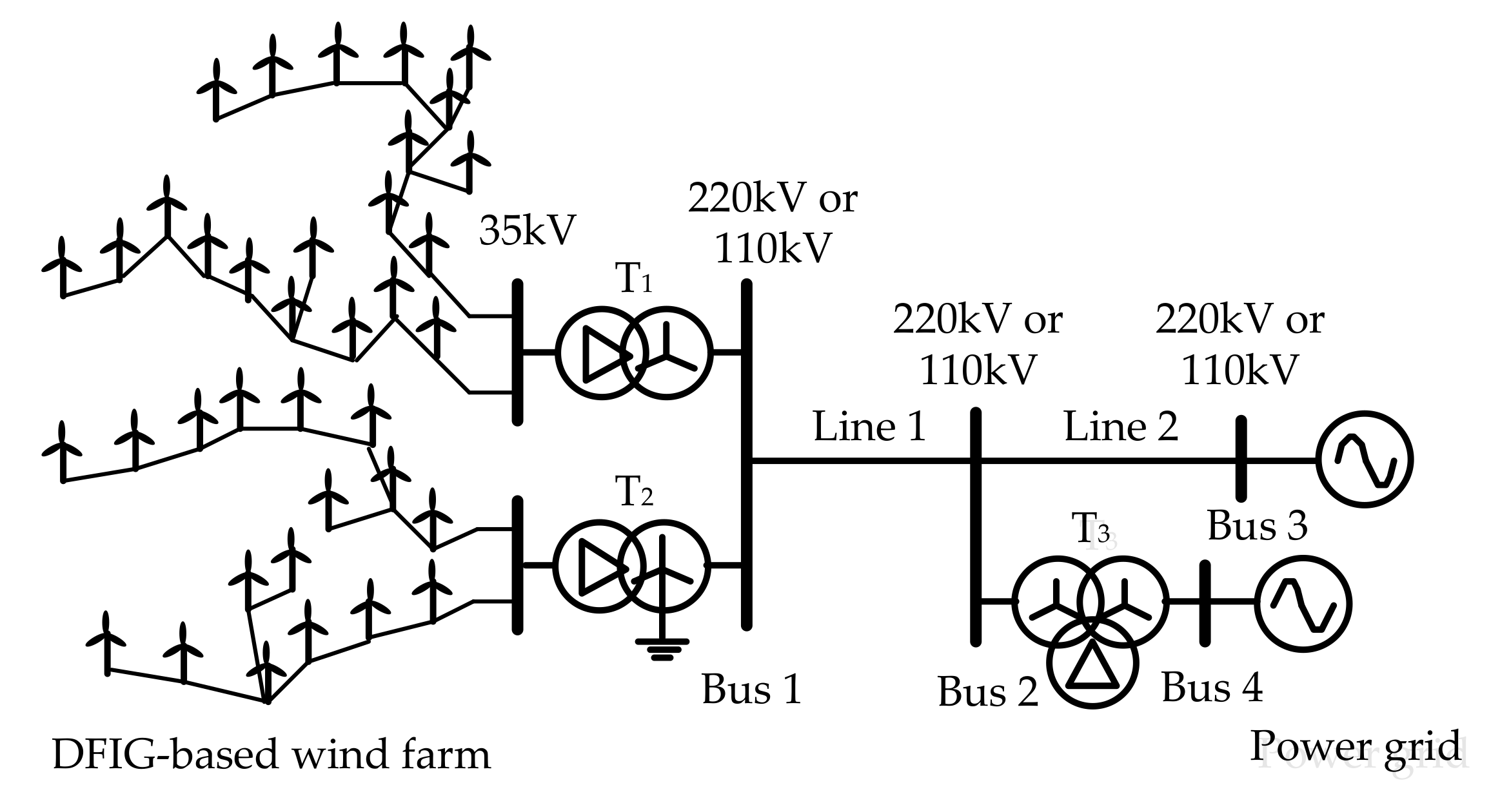
Areas with abundant wind energy are generally far from load centers. Therefore, large-scale wind farms are established and wind power is transmitted to the power system over long distances. The typical DFIG-based wind farm is shown in Figure 1. The outlet voltage of the DFIG is generally 690 V. The wind power is transmitted through a wind turbine unit transformer, collector system, substation, and transmission lines. The voltage level of the collector system is usually 35 kV and the voltage levels of the transmission line are usually 110 kV or 220 kV. Notably, the 35 kV system is not grounded, and the neutral point of the high-voltage system is directly grounded.
Figure 2 shows a typical DFIG with a rotor crowbar protection circuit. It mainly consists of a wind turbine, gearbox, asynchronous generator, RSC, grid side converter (GSC), rotor crowbar protection circuit, and control system. The DFIG stator is directly connected to the grid, whereas the rotor is connected to the grid by a back-to-back converter. The converter system enables variable speed operation of the wind turbine by decoupling the power system electrical frequency and the rotor mechanical frequency. A more detailed description of the DFIG system together with its control was previously reported [32].
2.1. DFIG Short Circuit Current
The transformer connecting the DFIG to the grid is generally a connection; therefore, only the positive and negative sequence components of a DFIG during faults need to be analyzed. A space vector description was used to present the generalized induction machine equations [7,16,17]. Using a generator convention for the stator windings and a motor convention for the rotor windings, the stator and rotor voltage equations and flux linkage equations in a stationary reference frame are expressed as:
where , , and represent the voltage space vector, current space vector, and flux linkage space vector, respectively; ω is the electrical angular velocity; R is the per-phase resistance; subscripts s and r denote the stator and rotor quantities, respectively; Ls and Lr are the per-phase stator and rotor self-inductances, respectively; and Lm is the per-phase mutual inductance; and D is the time-differential operator.
By solving Equation (2), the current can be written as equation of the flux linkages as:
where .
Assuming that, at time t = 0, an asymmetrical short circuit fault occurs at the DFIG. The post-fault stator voltage is:
where and are the positive and negative sequence voltages, respectively; A is the voltage sag ratio; Vpre is the amplitude of the pre-fault stator voltage; V2 is the amplitude of the post-fault stator negative sequence voltage; and and are the phase angles of and at time t = 0, respectively. The post-fault stator positive and negative sequence flux linkage are obtained in Equation (5). The detailed derivation is presented in Appendix A (i).
where is the stator decaying time constant; and are the natural component and forced component of , respectively; and and are the natural component and forced component of , respectively.
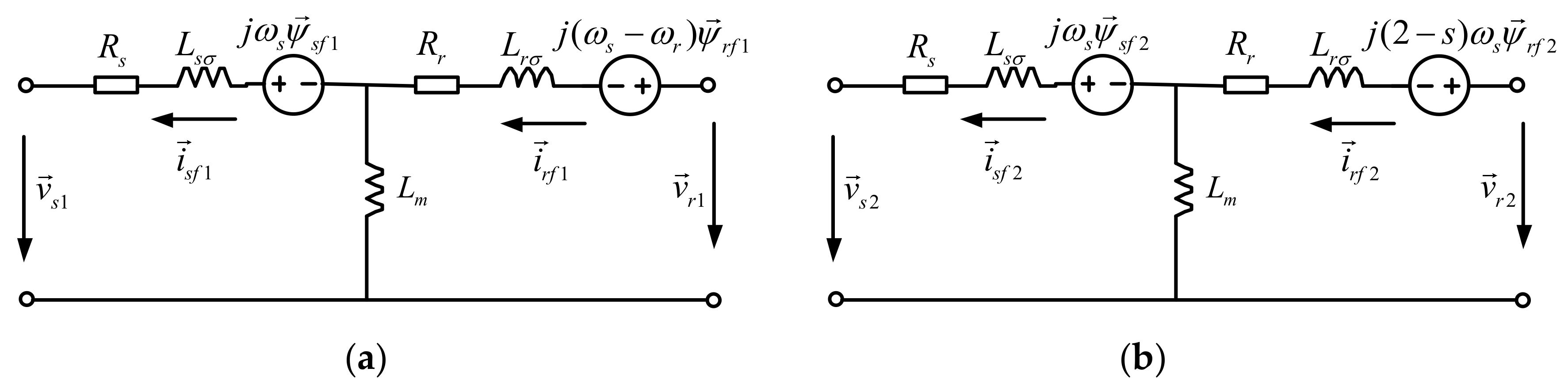
As for the steady state after a fault in a synchronous rotating reference frame, the positive sequence voltage equations and flux linkage equations are shown in Equations (6) and (7). The negative sequence voltage equations and flux linkage equations are shown in Equations (8) and (9), respectively. The equivalent circuits of DFIG in a synchronous rotating reference frame are shown in Figure 3 [17,33].
where Rr includes the rotor resistance and the crowbar resistance. is the DFIG slip. and are the stator and rotor leakage inductances, respectively, knowing that and .
Then, the post-fault rotor positive and negative sequence flux linkages are obtained in Equation (10), respectively. The detailed derivation is presented in Appendix A (ii).
where is the rotor decaying time constant; and are the natural component and forced component of , respectively; and and are the natural component and forced component of , respectively; , , and ; is the pre-fault rotor flux linkage.
Substituting Equations (5) and (10) into Equation (3), the stator positive and negative sequence short circuit currents can be obtained:
According to Equation (11), the stator short circuit current consists of a decaying direct current (DC) component, a decaying AC component at rotor speed frequency, and a forced AC component at synchronous frequency. Especially when the voltage sag is deep, meaning A is large, the amplitude of the forced AC component will be small, and the decaying DC component and decaying AC component will be the main components of the short circuit current. The short circuit current of a DFIG is the basis for researching the fault characteristics of the DFIG-based wind farm connected to transmission lines.
2.2. Fault Analysis of the DFIG-Based Wind Farm without LVRT Capability
If a DFIG-based wind farm does not have LVRT capability, the wind farm will immediately be removed from the grid when a fault occurs, and no short circuit current will be provided by DFIGs. When the high voltage side of the main transformer grounded provides a zero-sequence circuit, short circuit current on the transmission line of the wind farm side still exists under a ground fault. Figure 4 shows a real fault case where a single-phase ground fault occurred on the transmission line connected to a DFIG-based wind farm without LVRT capability. The wind power system details are presented in Appendix B.
In Figure 4, is the wind farm side short circuit current on the transmission line and , , , and are phase A, phase B, phase C, and zero sequence current of , respectively; is zero sequence impedance of the wind farm side, and it consists of the zero sequence impedance of the transformer grounded and transmission line; , , are the zero sequence, positive sequence, and negative sequence impedance of the grid side, respectively; and is the grid voltage before the fault. Due to the disconnection of the wind farm, the wind farm side positive and negative sequence circuits are equal to open roads, as shown in Figure 4a. There is no positive or negative sequence current on the wind farm side. However, the ground point of transformer T2 provides a zero-sequence circuit. The wind farm side three-phase currents on the transmission line are all zero sequence components, as shown in Figure 4b. The fault occurs at 30 ms and the fault duration is about 40 ms; then, the differential protection initiates and the circuit breaker trips. Except for the first few milliseconds of the transient process, , , , and are basically the same after the fault. That is to say, the short circuit current on the transmission line connected to the wind farm only contains zero-sequence components.
2.3. Fault Analysis of the DFIG-Based Wind Farm with LVRT Capability
For a DFIG-based wind farm with LVRT capability, the wind farm remains connected to the power grid when a fault occurs on transmission line. The capacity of a wind farm is generally much smaller than that of the power grid. The equivalent impedance of the wind farm converted from 690 V to a high voltage level is much larger than the equivalent impedance of the grid. The activation of the crowbar circuit further increases the equivalent impedance of the wind farm. Therefore, compared with the traditional power system, the wind farm side is a weak power supply system.
According to the above analysis in Section 2.1, the fault current consists of a decaying DC component, a decaying AC component at rotor speed frequency, and a forced AC component at synchronous frequency. Especially when the voltage sag is deep, the AC component at rotor speed frequency is the main AC component at the beginning of the fault. The DFIG rotor speed is generally 0.7 to 1.3 pu. Thus, the main frequency component of the wind farm side current is a 35–65 Hz AC component in the early stage of the fault, although the voltage is mainly 50 Hz due to the grid support. That is to say, the wind farm side shows current frequency deviation during disturbances. Two real fault cases are provided to illustrate the fault characteristics of the wind farm: a single-phase ground fault and a phase-to-phase short circuit fault on the transmission lines connected to DFIG-based wind farms with LVRT capability. As for the balanced fault, the detailed work has been done in papers [28,29].
2.3.1. The Single-Phase Ground Fault Case
The 35 kV system of wind farm is not grounded. The zero-sequence impedance of the wind farm only contains the zero-sequence impedance of transformer grounded and transmission line when a fault occurs on the transmission line. Therefore, the zero-sequence current of the wind farm is relatively large and is not influenced by the DFIG. Due to the weak power supply of the wind farm, the positive and negative sequence currents are small. The zero-sequence current is the main component of the wind farm side current when a ground fault occurs. For the real DFIG-based wind farm shown in Figure 4, the DFIG is equipped with LVRT technology afterwards. A single-phase ground fault occurs on Line 1 and the real fault waveform records are shown in Figure 5.
For the DFIG-based wind farm power system shown in Figure 4, the fault k occurs at 0.04 s and the fault duration is 40–60 ms; then, the differential protection initiates and the circuit breaker trips. The measured fault currents at the two terminals of the Line 1 are shown in Figure 5a,b separately. Obviously, the phase B current of the grid side is much larger than that of the wind farm side during the fault. Since wind farm is a weak power supply system, the short circuit current of the wind farm is small, hence the differences of the three-phase currents is not obvious. In order to observe the fault currents provided by the wind farm in detail, the measured currents on the high-voltage side of the transformer T2 are shown in Figure 5c. The RMS values of the positive, negative and zero-sequence currents are shown in Figure 5d. The three-phase short circuit currents are essentially coincident and the zero sequence current is much larger than the positive and negative sequence currents. In summary, for ground faults, the fault current of the wind farm side is dominated by the zero sequence current, the frequency of which is 50 Hz. The frequency deviation is not obvious.
2.3.2. The Phase-to-Phase Short Circuit Fault Case
For the similar wind farm with LVRT capability, the topology is shown in Figure 4, but the voltage level of the transmission lines are 110 kV and the transformer T3 is out of operation. The wind power system details are presented in Appendix B. Figure 6 shows the real waveform records when a phase-A-to-phase-B fault occurs on Line 2.
The fault occurs at 0.05 s and the fault duration is about 180 ms; then, the distance protection initiates and the circuit breaker trips. As shown in Figure 6a, the phase A voltage is approximately equal to the phase B voltage after the fault. It can be seen From Figure 6b that the fault currents increased after fault, fault current consists of a decaying DC component, a decaying AC component at rotor speed frequency, and a forced AC component at synchronous frequency according to Equation (11). The natural components of fault currents gradually decrease. At last, the forced component remains and the value is small than load current because of voltage sags. For the phase-to-phase short circuit fault, DFIG-based wind farms only provide positive and negative sequence currents, the amplitudes of which are small, and no zero-sequence current exists. Therefore, the frequency deviation is obvious. Figure 6c shows the wind farm side voltage and the current waveforms of phase A, which is extracted from Figure 6a,b. The frequency of the phase A voltage remains 50 Hz because of the system voltage support. At the beginning of the fault, the frequency of the phase A current is obviously greater than 50 Hz due to the existence of decaying AC component at rotor speed frequency, as shown in Figure 6d.
3. Distance Protection and Its Improvement Method for the Transmission Line Connected to DFIG-Based Wind Farms
3.1. Application of Conventional Distance Protection
Distance protection exploits the fact that the voltage and current change at the same time when a fault occurs. The ratio of the measured voltage to the measured current represents the distance from the fault point to the relay location. The distance protection initiates if the fault distance is less than the setting value. For a conventional power grid with the synchronous generators, the measured voltages and currents in the relay location are mainly at nominal frequency. The Fourier algorithm is usually used to measure voltages and currents correctly. However, the short circuit currents of wind farm side may contain rotor speed frequency AC components, which cannot be filtered accurately. As a result, the calculation result error using the Fourier algorithm may be significantly large [34]. Then, the reliability of the distance protection based on nominal frequency voltage and current cannot be guaranteed. According to the real fault cases for phase-to-ground fault and phase-to-phase fault, the applicability of distance protection of the transmission line is analyzed.
3.1.1. Phase-to-Ground Fault
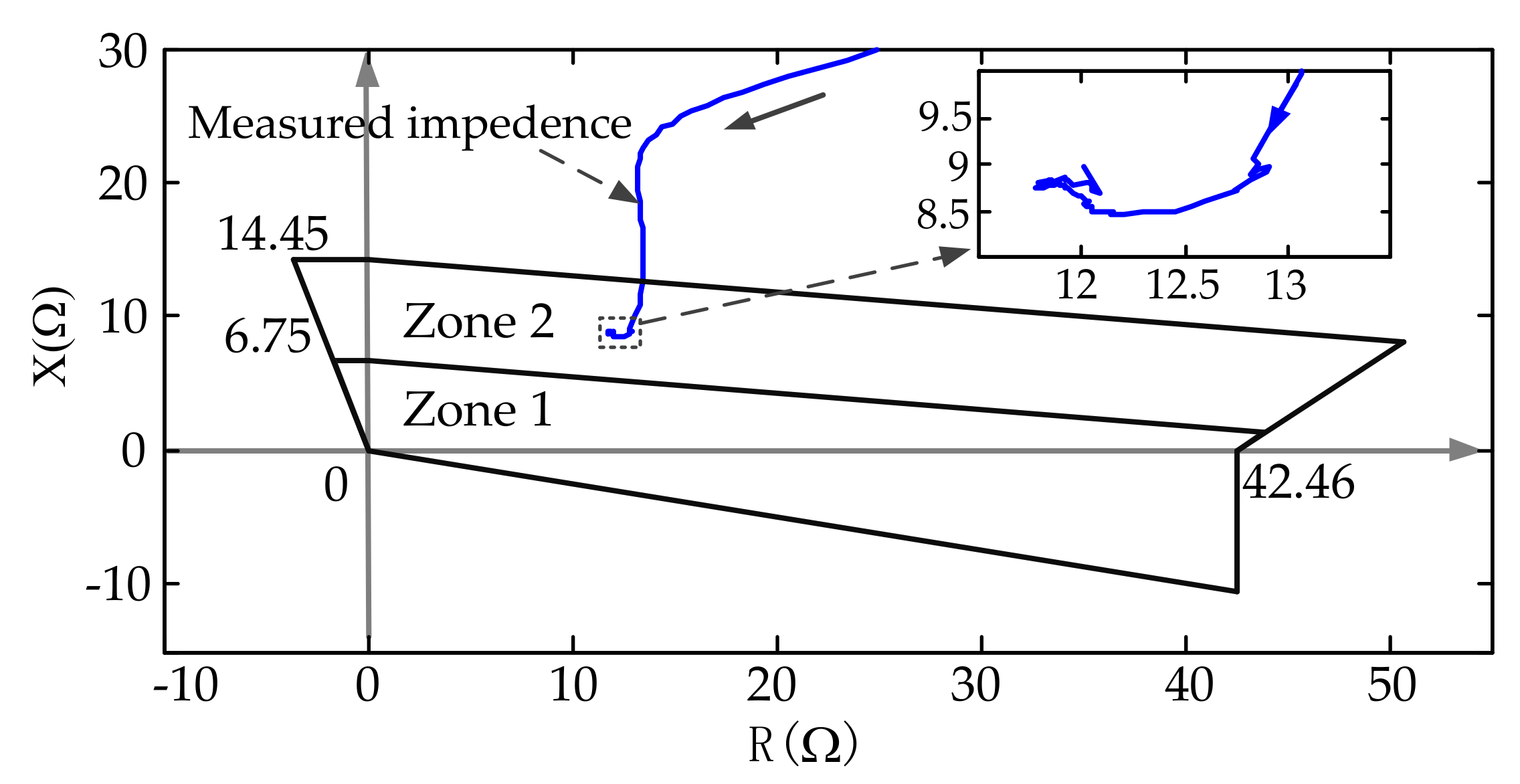
For the case of the single-phase ground fault outlined in Section 2.3.1, the fault currents of the wind farm side are dominated by the zero-sequence current, the frequency of which is 50 Hz. According to the real fault waveform data, the impedance trajectory calculated by the Fourier algorithm is shown in Figure 7.
In Figure 7, the blue line is the impedance trajectory measured by conventional distance protection. Zone 1 and Zone 2 are the polygon action areas of wind farm side instantaneous and time delay instantaneous distance protection on Line 1, respectively. 6.75 and 14.45 Ω are the instantaneous and time delay instantaneous distance protection setting values of the reactance, respectively. 42.46 Ω is the setting value of the ground resistance. Referring to Figure 4, the length of Line 1 is 22 km and the actual fault point is 21 km away from Bus 1 (the corresponding reactance is about 9 Ω). Thus, the impedance trajectory is beyond Zone 1 and lies in Zone 2. From the magnified view of the impedance trajectory, the measured reactance is stable finally and close to 9 Ω during the fault. That is to say, the conventional ground distance protection of the wind farm side is relatively reliable.
3.1.2. Phase-to-Phase Fault
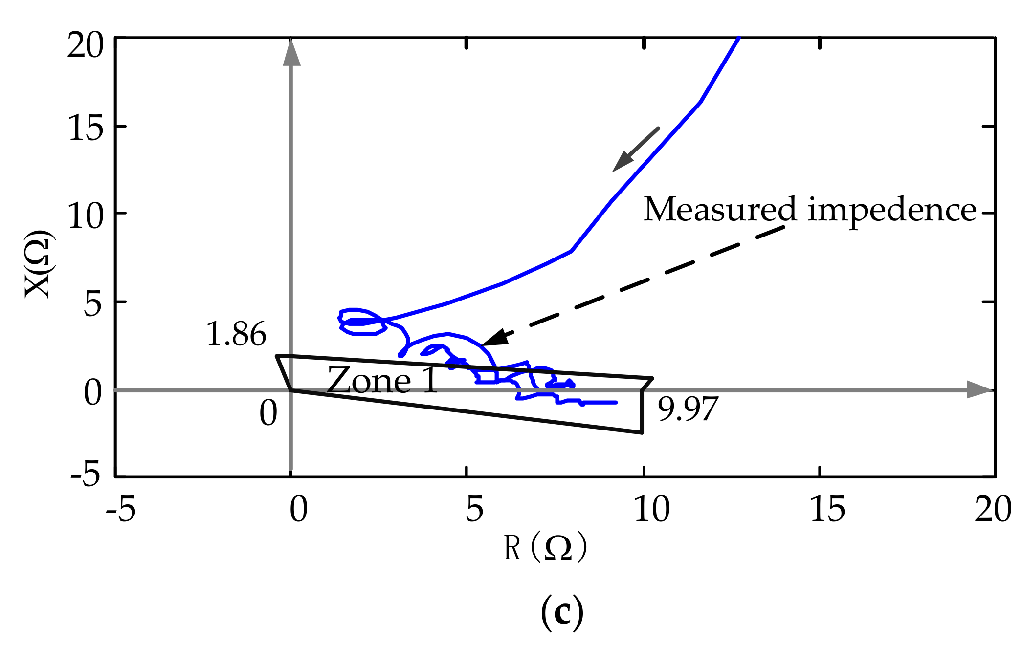
For the real phase-to-phase fault case mentioned in Section 2.3.2, the topology of wind farm is shown in Figure 4, but the voltage level of the transmission lines are 110 kV and the transformer T3 is out of operation. The phase-A-to-phase-B fault occurred on Line 2. However, the wind farm side phase-to-phase instantaneous distance protection on Line 1 maloperated. Obviously, the fault case is a maloperation accident. According to the real fault waveform records shown in Figure 6, the amplitude, phase and trajectories of the measured phase-A-to-phase-B impedance are calculated by the Fourier algorithm, as shown in Figure 8a–c, respectively.
It can be seen from Figure 8a,b that the amplitude and phase of the measured impedance are both constantly changing. In Figure 8c, the blue line is the impedance trajectory measured by conventional distance protection. Zone 1 is the polygon action area of wind farm side instantaneous distance protection on Line 1. 9.97 and 1.86 Ω are the instantaneous distance protection setting values of the resistance and reactance, respectively. It can be seen that the trajectory of the impedance enters Zone 1 and causes the maloperation of wind farm side phase-to-phase instantaneous distance protection on Line 1. The conventional instantaneous distance protection of the wind farm side is no longer reliable when a phase-to-phase fault occurs on a transmission line.
3.2. Time-Domain Distance Protection Based on the R-L Model
The method used to solve the differential equation based on the R-L time domain model is not involved in the signal frequency domain information. The method establishes the differential equations for the transmission line by using the instantaneous current and voltage values in the relay location. It is not affected by the DC component, the low-frequency component, or the fluctuation in the power grid frequency. Therefore, the differential equation algorithm can overcome the influence of the frequency deviation of the wind power system. If the distribution capacitance of the protected line can be ignored, then the line segment from the fault point to the relay location can be approximated by a resistor and an inductor series circuit. When a fault occurs in a certain point on the line, the differential equation in the relay location is:
where R and L are the positive sequence resistance and inductance of the fault point to the relay location, respectively, and u and i are the instantaneous voltage and current values of the relay location, respectively. When using a microcomputer, the derivative of the current can be calculated by the difference equation. Then, the unknown part of the differential equation is only R and L. In theory, the equations can be solved with only three sampling points. To ensure the accuracy of the solution, the voltage and current are sampled multiple times. These values are substituted into Equation (12) to obtain a series of difference equations. Then, the equations are solved with the least-squares method [35]. Set the sampling period to be Ts. tk and tk+1 are two sampling times, and the corresponding measured voltage and current sampling value are, respectively, uk, uk+1, ik, and ik+1. For simplicity, set yk = (uk + uk+1)/2, xk = (ik + ik+1)/2, and Dk = (ik+1 − ik)/Ts. Substituting them into Equation (12) and N observations are performed, the sum of squares of each error is expressed as:
where N is the length of data window. N can vary with the estimation accuracy requirement. The larger the N, the better the estimation accuracy. The least-squares method involves finding the R and L, which minimize the value of J, so the partial derivative of R and L are equal to zero and two equations are obtained. Solve the two equations, and the calculation formula of the estimated value of the resistance and the inductance are obtained:
3.3. Case Studies
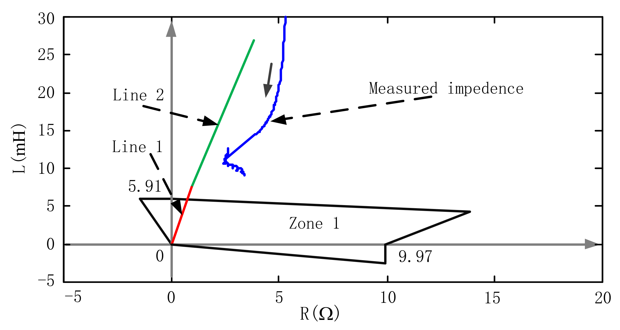
According to the real phase-to-phase fault case mentioned in Section 2.3.2, the trajectory of impedance measured by Equations (14) and (15) is shown in Figure 9. The red line and green line in Figure 9 are obtained based on the real resistance and inductance parameters of Line 1 and Line 2, respectively. Zone 1 is the polygon action areas of wind farm side instantaneous distance protection on Line 1, and 9.97 Ω and 1.86 mH are setting values of resistance and inductance, respectively. Actually, the fault occurs on Line 2. Compared with Figure 8c, the measured impedance trajectory does not enter Zone 1 in Figure 9 and the wind farm side instantaneous distance protection on Line 1 will not maloperate. Thus, the reliability of distance protection on wind farm side transmission lines is guaranteed when using the time-domain distance protection method proposed in this paper.
According to the real wind farm mentioned in Section 2.3.1, the corresponding wind farm model is established by Matlab/Simulink (R2014a, MathWorks, Natick, MA, USA, 2014). The topology of the wind farm is shown in Figure 4. The wind farm is equipped with 132 DFIGs with LVRT capability, and each main transformer connects 66 DFIGs. The parameters of a real DFIG and transmission lines are shown in Appendix B. The detailed model and control strategy of DFIG can be found in previous studies [14,36].
This paper mainly researched the fault characteristics of DFIG-based wind farms connected to transmission lines and its influence on relay protection. The duration of the fault is relatively short, so the wind speed of the wind farm is considered as unchanged during the research process. For the convenience of research, all wind turbines are set to operate under the same conditions. Additionally, the impedance of the collector system is ignored.
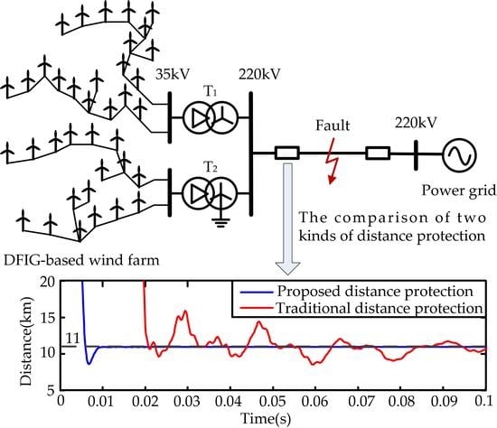
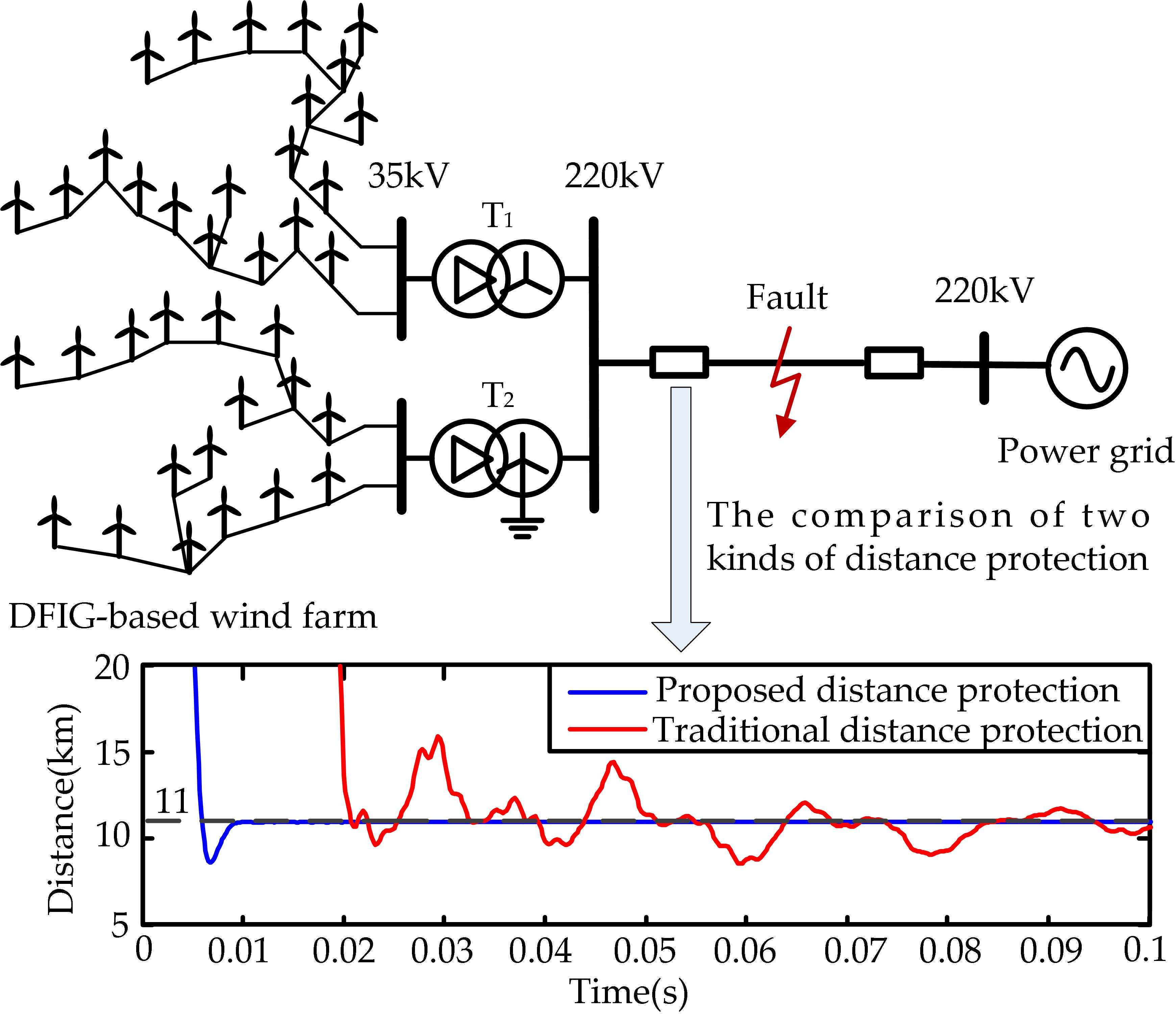
To compare the time-domain distance protection method with the traditional distance protection method based on the Fourier algorithm, the following three conditions are given as typical simulation examples: a phase A ground fault, a phase-A-to-phase-B fault, and a three-phase short circuit fault. The transition resistances are all zero. The fault points are all 11 km away from Bus 1 on Line 1. The wind speed is 11 m/s before the fault. The comparison of two kinds of distance protection methods used on the wind farm side transmission lines connected to DFIG-based wind farms are shown in Figure 10.
In Figure 10, the red lines are the distance measured by Fourier algorithm and the blue lines are the distance measured by time-domain method. The faults occur at 0 s and the rotor speed before the fault is greater than the synchronous speed. Due to the existence of a rotor speed frequency AC component, the distance calculation results, which are obtained from the traditional distance protection method based on the Fourier algorithm, fluctuate considerably. The error of ground fault is smaller due to the domination of the zero-sequence current. The time-domain method proposed in this paper is not affected by the rotor speed frequency component, the distance calculation results converge to the real fault distance within a dozen milliseconds.
To further verify the performance of the time-domain method, three fault points at 5, 10 and 15 km are selected on Line 1. The following four conditions are given as typical simulation examples: a phase A ground fault, a two-phase ground fault, a phase-to-phase short circuit fault and a three-phase short circuit fault. The transition resistances are all zero. The wind speed is 11 m/s before the fault and the corresponding rotor speed is greater than the synchronous speed. The data of 20–40 ms after faults are selected to calculate the errors of two methods’ measurement results. The error calculation formula is shown as:
where xi and xt are separately the measurement value and true value of fault distance. The errors of fault distance measurement results are separately shown in Table 1 and Table 2.
According to the two tables, the accuracy of the calculation results using the time-domain method is significantly high, and no error is more than 1%. The errors of the calculation results using the Fourier method are significantly bigger than that of the time-domain method. The time-domain distance protection method can accurately and quickly identify fault distances when faults occur on the transmission line connected to a DFIG-based wind farm.
4. Conclusions
This paper analyzes the composition of DFIG short circuit current. Moreover, using data of real fault cases, this paper illustrates the fault characteristics of DFIG-based wind farms connected to transmission lines and the corresponding applicability of the conventional distance protection based on the Fourier algorithm.
The DFIG short circuit current consists of a decaying DC component, a decaying AC component at rotor speed frequency, and a forced AC component at synchronous frequency. Wind farm is a weak power supply system. The short circuit current of wind farm side is much smaller than that of the power grid side. Additionally, the zero-sequence current will be the main component of the wind farm side short circuit current when a ground fault occurs. The wind farm side may show current frequency deviation during disturbances. The wind farm side voltage of transmission line is nominal frequency due to the grid support, whereas its frequency may no longer be nominal due to the existence of rotor speed frequency component. The conventional ground distance protection based on the Fourier algorithm is still relatively reliable, whereas the phase-to-phase instantaneous distance protection is no longer reliable for the transmission line connected to a DFIG-based wind farm. Finally, a time-domain distance protection method based on the R-L model and least-squares algorithm is proposed to solve the problem. The time-domain method accurately and quickly identified fault distances when faults occur on the transmission line connected to a DFIG-based wind farm. The efficacy of the proposed method is validated with real fault cases and simulation. The proposed method is immune to the frequency variation. Thus, it overcomes the defect of traditional distance protection. With the help of the proposed method, Relay Protection Equipment Manufacturers can improve the equipment level of technology, and the grid companies can improve the safe operation level of the power system.
Acknowledgments
This work was supported by the National Science Foundation for Excellent Young Scholars of China (Grant No. 51422703).
Author Contributions
Bin Li conceived the study and wrote the paper; Junyu Liu performed the experiments and analyzed the data and wrote the manuscript; Xin Wang analyzed the topology and fault characteristics of DFIG; Lili Zhao contributed to the data of wind farms and DFIG.
Conflicts of Interest
The authors declare no conflict of interest.
Appendix A
(i) The derivation of stator flux linkage
From Equation (1), ignore Rs, there is
The solution of Equation (A1) can be written as:
It can be found that the response of the stator flux after the fault consists of two components: natural flux linkage and forced flux linkage . can be determined by the post-fault terminal voltage:
It is well known that the flux can only change continuously. Thus, there is
and pre-fault stator flux linkage is
Therefore, the stator natural flux linkage is obtained as:
(ii) The derivation of rotor flux linkage.
Appendix A.1. The Derivation of Pre-Fault Rotor Flux Linkage
Using a generator convention for the stator windings and a motor convention for the rotor windings, the flux linkage equations in a synchronous dq reference frame are expressed as [20]:
The stator active and reactive power output of DFIG can be expressed as [37]:
Assuming that the d-axis of the reference frame is aligned with the stator flux linkage vector,
can be obtained.
Substituting Equation (A10) into Equation (A7),
can be obtained.
Substituting Equation (A11) into Equation (A9),
can be obtained.
Based on Equations (A8), (A12) and (A13), the rotor flux linkage equation is expressed as:
If Vs = Vpre and the DFIG stator terminal instantaneous complex power before the fault is , then pre-fault rotor flux linkage is
Appendix A.2. The Derivation of Post-Fault Rotor Flux Linkage
After fault, the crowbar circuit is activated and the RSC is shorted so that and are both zero in Figure 3. Furthermore, the forced ac component of rotor flux rotates synchronously so that its amplitude is constant in the synchronous rotating reference frame. Therefore, and are both zero. Then solving Equations (6)–(9), respectively, the post-fault steady rotor positive and negative sequence flux linkages are expressed as:
where . For simplicity, set , .
The flux can only change continuously, so there is
According to Equations (A15)–(A17), the rotor natural flux linkage is obtained as:
where is rotor decaying time constant.
Appendix B
The real DFIG-based wind farm shown in Figure 4 is equipped with 132 DFIGs and the total capacity is 198 MW. At the beginning, the DFIG is not equipped with LVRT technology. But then, the DFIG is equipped with LVRT technology by technological transformation. The transmission line parameters of the wind farm are shown in Table A1. The main protection of the transmission line is current differential protection and the backup protection is conventional distance protection.

Table A1.
The 220 kV transmission line parameters.
| Parameter Name | Line 1 | Line 2 |
|---|---|---|
| Length (km) | 22.018 | 70.202 |
| Z1 (Ω/km) | 0.080 + j0.430 | 0.048 + j0.320 |
| Z0 (Ω/km) | 0.360 + j1.000 | 0.317 + j1.000 |
The real DFIG-based wind farm mentioned in Section 2.3.2 is equipped with 56 DFIGs and the total capacity is 84 MW. The DFIG is equipped with LVRT technology. The transmission line parameters of the wind farm are shown in Table A2. The main protection of the transmission line is conventional distance protection.
Table A2.
The 110 kV transmission line parameters.
| Parameter Name | Line 1 | Line 2 |
|---|---|---|
| Length (km) | 5.325 | 16.168 |
| Z1 (Ω/km) | 0.113 + j0.419 | 0.154 + j0.407 |
| Z0 (Ω/km) | 0.871 + j1.085 | 0.593 + j1.216 |
The parameters of a real DFIG used in the wind farm which is shown in Figure 4 are shown in Table A3.
Table A3.
The parameters of DFIG.
| Parameter Name | Value | Parameter Name | Value (p.u.) |
|---|---|---|---|
| Nominal capacity | Stator resistance | ||
| Rated stator voltage | Stator leakage inductance | ||
| System frequency | Rotor resistance | ||
| Rated voltage of DC-link | Rotor leakage inductance | ||
| Pairs of poles | Mutual inductance | ||
| Nominal wind speed | Crowbar resistance |
References
- Hossain, M.M.; Ali, M.H. Future research directions for the wind turbine generator system. Renew. Sustain. Energy Rev. 2015, 49, 481–489. [Google Scholar] [CrossRef]
- Li, H.; Chen, Z. Overview of different wind generator systems and their comparisons. IET Renew. Power Gener. 2008, 2, 123–138. [Google Scholar] [CrossRef]
- Muller, S.; Deicke, M.; De Doncker, R.W. Doubly fed induction generator systems for wind turbines. IEEE Trans. Ind. Appl. Mag. 2002, 8, 26–33. [Google Scholar] [CrossRef]
- Hughes, F.M.; Anaya-Lara, O.; Jenkins, N.; Strbac, G. Control of DFIG based wind generation for power network support. IEEE Trans. Power Syst. 2005, 20, 1958–1966. [Google Scholar] [CrossRef]
- Iwanski, G.; Koczara, W. DFIG-based power generation system with UPS function for variable-speed applications. IEEE Trans. Ind. Electron. 2008, 55, 3047–3054. [Google Scholar] [CrossRef]
- Marques, G.D.; Sousa, D.M. Understanding the doubly fed induction generator during voltage dips. IEEE Trans. Energy Convers. 2012, 27, 421–461. [Google Scholar] [CrossRef]
- Ling, Y.; Cai, X.; Wang, N. Rotor current transient analysis of DFIG-based wind turbines during symmetrical voltage faults. Energy Convers Manag. 2013, 76, 910–917. [Google Scholar] [CrossRef]
- The Grid Code 3. Available online: http//www.nationalgrid.com/uk/Electricity/Codes/gridcode (accessed on 1 January 2006).
- Transmission Code 2007—Network and System Rules of the German Transmission System Operators. Available online: https://www.bdew.de/ (accessed on 1 August 2007).
- Inspection and Quarantine of China. Technical Rule for Connecting Wind Farm to Power System; Technical Report for Inspection and Quarantine of China; Inspection and Quarantine of China: Beijing, China, 2011.
- Rahim, A.H.M.A.; Nowicki, E.P. Supercapacitor energy storage system for fault ride through of a DFIG wind generation system. Energy Convers. Manag. 2012, 59, 96–102. [Google Scholar] [CrossRef]
- Cardenas, R.; Pena, R.; Alepuz, S.; Asher, G. Overview of control systems for the operation of DFIGs in wind energy applications. IEEE Trans. Ind. Electron. 2013, 60, 2776–2798. [Google Scholar] [CrossRef]
- Akhmatov, V. Induction Generators for Wind Power; Multi-Science Publishing Company Ltd.: Brentwood, UK, 2005. [Google Scholar]
- Morren, J.; de Haan, S.W.H. Ride through of wind turbines with doubly-fed induction generator during a voltage dip. IEEE Trans. Energy Convers. 2005, 20, 435–441. [Google Scholar] [CrossRef]
- Lopez, J.; Sanchis, P.; Roboam, X.; Marroyo, L. Dynamic behavior of the doubly-fed induction generator during three-phase voltage dips. IEEE Trans. Energy Convers. 2007, 22, 709–717. [Google Scholar] [CrossRef]
- Pannell, G.; Atkinson, D.J.; Zahawi, B. Analytical study of grid-fault response of wind turbine doubly fed induction generator. IEEE Trans. Energy Convers. 2010, 25, 1081–1091. [Google Scholar] [CrossRef]
- Sulla, F.; Svensson, J.; Samuelsson, O. Symmetrical and unsymmetrical short-circuit current of squirrel-cage and doubly-fed induction generators. Electr. Power Syst. Res. 2011, 81, 1610–1618. [Google Scholar] [CrossRef]
- Morren, J.; de Haan, S.W.H. Short-circuit current of wind turbines with doubly fed induction generator. IEEE Trans. Energy Convers. 2007, 22, 174–180. [Google Scholar] [CrossRef]
- Lopez, J.; Gubia, E.; Sanchis, P.; Roboam, X.; Marroyo, L. Wind turbines based on doubly fed induction generator under asymmetrical voltage dips. IEEE Trans. Energy Convers. 2008, 23, 321–330. [Google Scholar] [CrossRef]
- Kong, X.; Zhang, Z.; Yin, X.; Wen, M. Study of fault current characteristics of the DFIG considering dynamic response of the RSC. IEEE Trans. Energy Convers. 2014, 29, 278–287. [Google Scholar]
- Ouyang, J.; Xiong, X. Dynamic behavior of the excitation circuit of a doubly-fed induction generator under a symmetrical voltage drop. Renew. Energy 2014, 71, 629–638. [Google Scholar] [CrossRef]
- Xiao, F.; Zhang, Z.; Yin, X. Fault Current Characteristics of the DFIG under Asymmetrical Fault Conditions. Energies 2015, 8, 10971–10992. [Google Scholar] [CrossRef]
- Naggar, A.E.; Erlich, I. Fault current contribution analysis of doubly fed induction generator-based wind turbines. IEEE Trans. Energy Convers. 2015, 30, 874–883. [Google Scholar] [CrossRef]
- El-Naggar, A.; Erlich, I. Short-circuit current reduction techniques of the doubly-fed induction generator based wind turbines for fault ride through enhancement. IET Renew. Power Gener. 2017, 11, 1033–1040. [Google Scholar] [CrossRef]
- Pannell, G.; Atkinson, D.J.; Zahawi, B. Minimum-threshold crowbar for a fault-ride-through grid-code-compliant DFIG wind turbine. IEEE Trans. Energy Convers. 2010, 25, 750–759. [Google Scholar] [CrossRef]
- Xiao, S.; Yang, G.; Zhou, H.; Geng, H. An LVRT Control Strategy Based on Flux Linkage Tracking for DFIG-Based WECS. IEEE Trans. Ind. Electron. 2013, 60, 2820–2832. [Google Scholar] [CrossRef]
- Piwko, R.; Miller, N.; Sanchez-Gasca, J.; Yuan, X.; Dai, R.; Lyons, J. Integrating large wind farms into weak power grids with long transmission lines. In Proceedings of the Transmission and Distribution Conference and Exposition: Asia and Pacific, Dalian, China, 18–18 August 2005; pp. 1–7. [Google Scholar]
- Hooshyar, A.; Azzous, M.A.; El-Saadany, E.F. Distance protection of lines connected to induction generator-based wind farms during balanced faults. IEEE Trans. Sustain. Energy 2014, 5, 1193–1203. [Google Scholar] [CrossRef]
- Hooshyar, A.; Azzous, M.A.; El-Saadany, E.F. Three-Phase Fault Direction Identification for Distribution Systems with DFIG-Based Wind DG. IEEE Trans. Sustain. Energy 2014, 5, 747–756. [Google Scholar] [CrossRef]
- Saleh, S.A.; Aljankawey, A.S.; Meng, R. Impacts of grounding configurations on responses of ground protective relays for DFIG-Based WECSs-Part I: Solid ground faults. IEEE Trans. Ind. Appl. 2015, 51, 2804–2818. [Google Scholar] [CrossRef]
- Saleh, S.A.; Aljankawey, A.S.; Meng, R. Impacts of grounding configurations on responses of ground protective relays for DFIG-Based WECSs-Part II: High-Impedance Ground Faults. IEEE Trans. Ind. Appl. 2016, 52, 1204–1214. [Google Scholar]
- Arachchige, L.N.W.; Rajapakse, A.D.; Muthumuni, D. Implementation, Comparison and Application of an Average Simulation Model of a Wind Turbine Driven Doubly Fed Induction Generator. Energies 2017, 10, 1726. [Google Scholar] [CrossRef]
- Zheng, Z.; Yang, G.; Geng, H. Short circuit current analysis of DFIG-type WG with crowbar protection under grid faults. In Proceedings of the International Symposium on Industrial Electronics, Hangzhou, China, 28–31 May 2012; pp. 1072–1079. [Google Scholar]
- Smith, J.C.; Milligan, M.R.; DeMeo, E.A.; Parsons, B. Utility wind integration and operating impact state of the art. IEEE Trans. Power Syst. 2007, 22, 900–908. [Google Scholar] [CrossRef]
- Li, B.; Duan, Z.; Wang, X.; Wu, J. Loss-of-excitation analysis and protection for pumped-storage machines during starting. IET Renew. Power Gener. 2016, 10, 71–78. [Google Scholar] [CrossRef]
- Yin, M.; Li, G.; Zhou, M.; Liu, G.; Zhao, C. Study on the Control of DFIG and Its Responses to Grid Disturbances. In Proceedings of the Power Engineering Society General Meeting, Montreal, QC, Canada, 18–22 June 2006; pp. 1–6. [Google Scholar]
- Abad, G.; Rodriguez, M.A.; Iwanski, G.; Poza, J. Direct Power Control of Doubly Fed Induction Generator Based Wind Turbines under Unbalanced Grid Voltage. IEEE Trans. Power Electron. 2010, 25, 442–452. [Google Scholar] [CrossRef]
Figure 1.
Topology of the doubly fed induction generator (DFIG)-based wind farm.

Figure 2.
A typical DFIG with a rotor crowbar protection circuit.
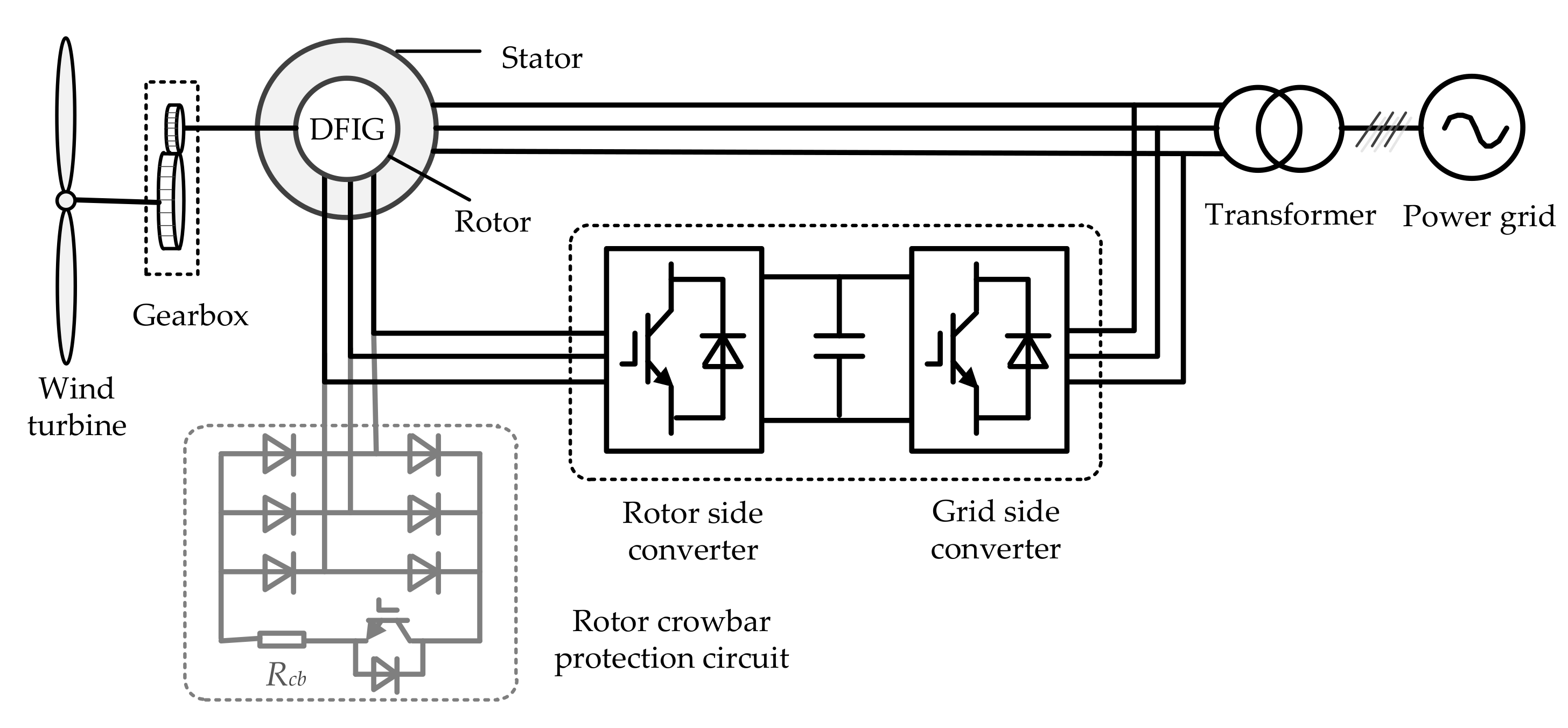
Figure 3.
The equivalent circuits of DFIG at the synchronous rotating reference frame: (a) the positive sequence equivalent circuit; and (b) the negative sequence equivalent circuit.
Figure 3.
The equivalent circuits of DFIG at the synchronous rotating reference frame: (a) the positive sequence equivalent circuit; and (b) the negative sequence equivalent circuit.

Figure 4.
The real fault case when a phase C ground fault occurs on the transmission line connected to DFIG-based wind farm without low voltage ride through (LVRT) capability.
Figure 4.
The real fault case when a phase C ground fault occurs on the transmission line connected to DFIG-based wind farm without low voltage ride through (LVRT) capability.
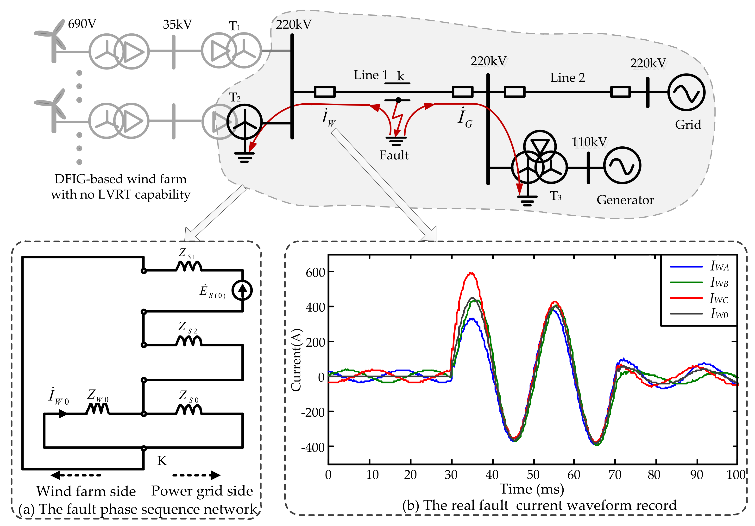
Figure 5.
The real fault waveform records when a phase B ground fault occurs on the transmission line connected to a DFIG-based wind farm with LVRT capability: (a) currents of the grid side; (b) currents of the wind farm side; (c) currents of the transformer T2; and (d) Root-Mean-Square (RMS) current values of the transformer T2.
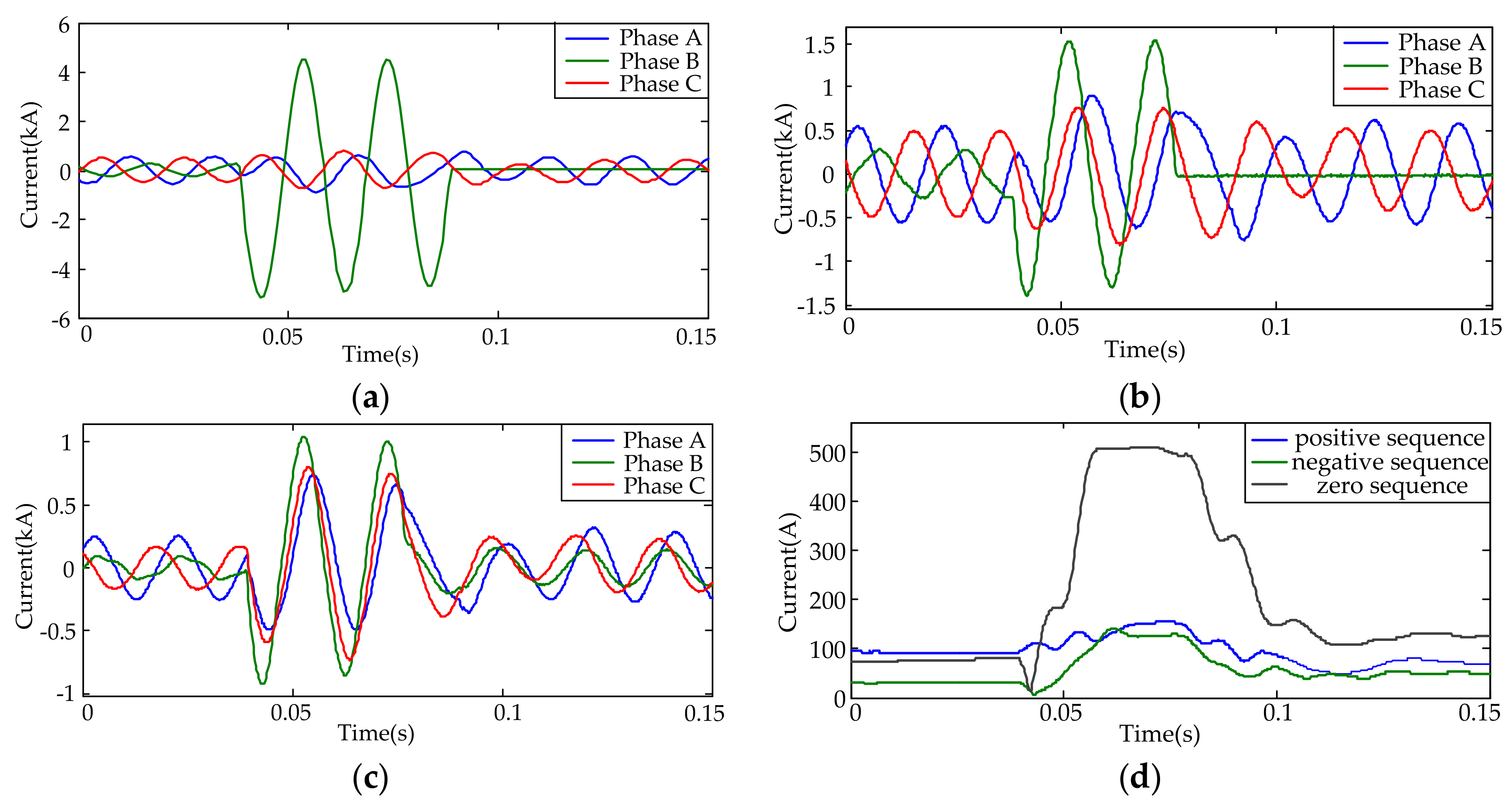
Figure 6.
The real fault waveform records when a phase-A-to-phase-B fault occurs on the transmission line connected to a DFIG-based wind farm with LVRT capability: (a) voltages of the wind farm side, (b) currents of the wind farm side, (c) phase A voltage and current of the wind farm side, and (d) phase A voltage frequency and current frequency of the wind farm side.
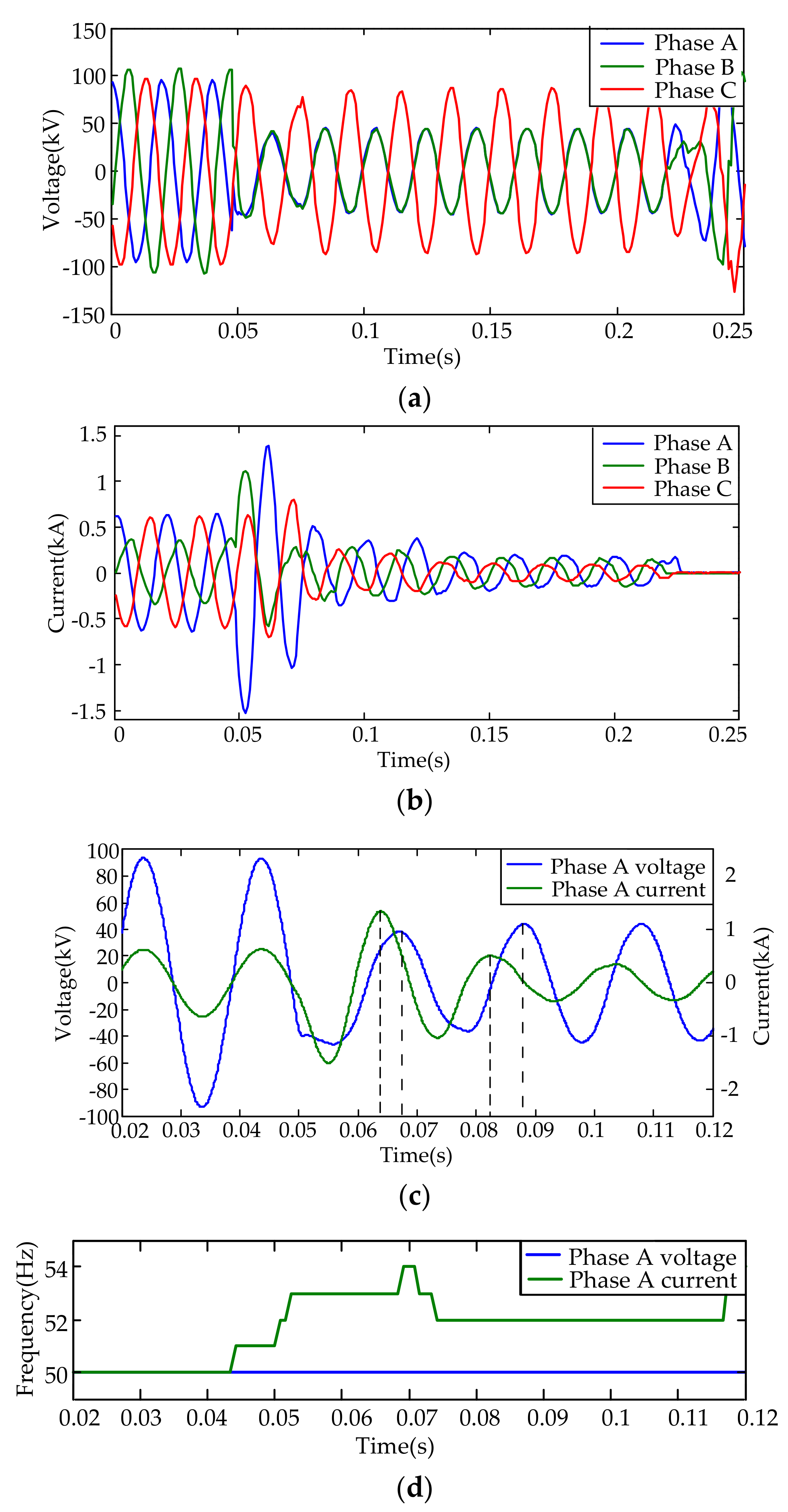
Figure 7.
The phase B impedance trajectory of the wind farm side when a phase B ground fault occurs on the transmission line connected to a DFIG-based wind farm.
Figure 7.
The phase B impedance trajectory of the wind farm side when a phase B ground fault occurs on the transmission line connected to a DFIG-based wind farm.

Figure 8.
The phase-A-to-phase-B impedance of the wind farm side when a phase-A-to-phase-B fault occurs on the transmission line connected to a DFIG-based wind farm: (a) the amplitude of impedance; (b) the angle of impedance; and (c) the trajectory of impedance.
Figure 8.
The phase-A-to-phase-B impedance of the wind farm side when a phase-A-to-phase-B fault occurs on the transmission line connected to a DFIG-based wind farm: (a) the amplitude of impedance; (b) the angle of impedance; and (c) the trajectory of impedance.
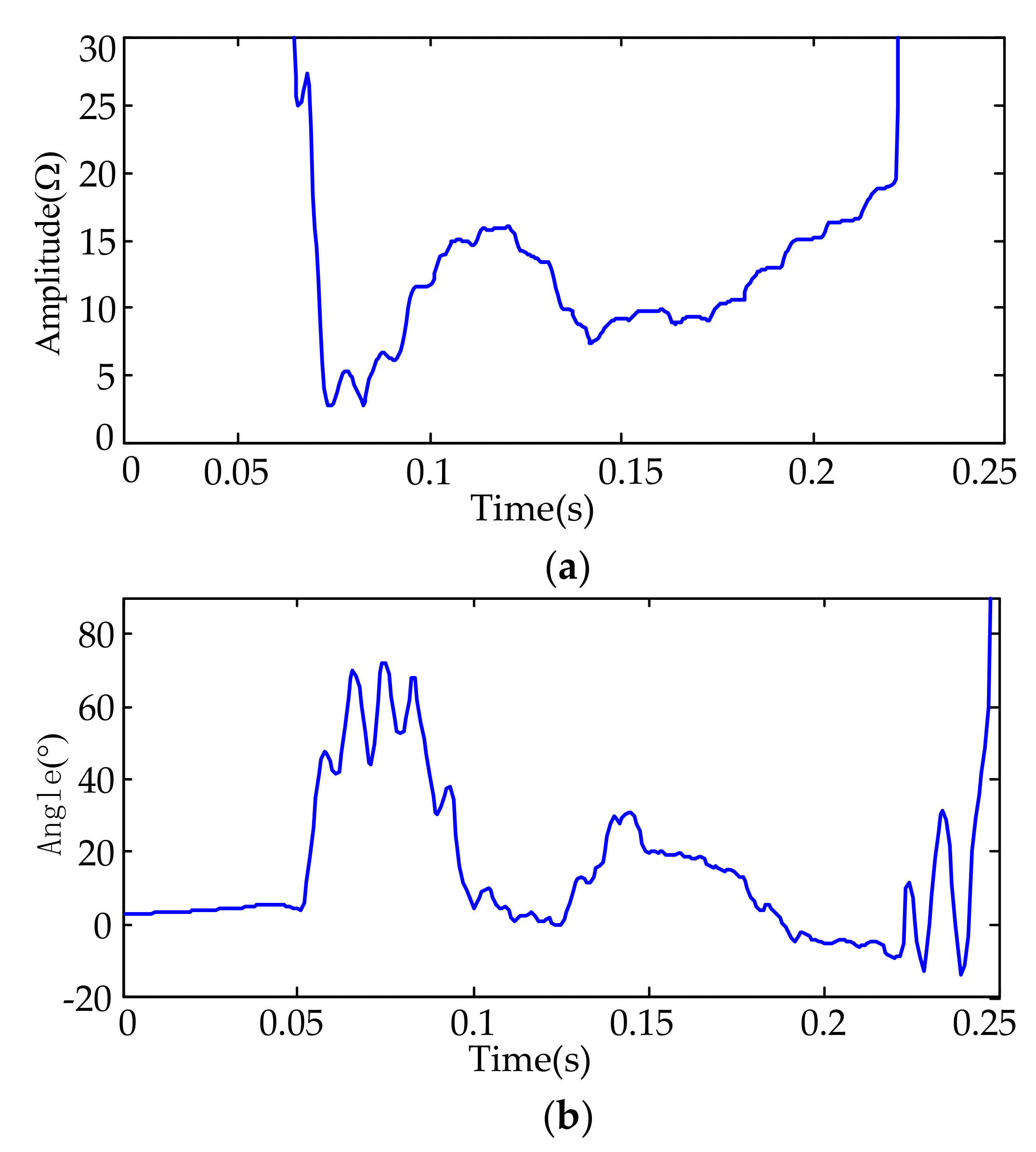

Figure 9.
The real phase-to-phase fault case’s trajectory of impedance measured with the time-domain method.
Figure 9.
The real phase-to-phase fault case’s trajectory of impedance measured with the time-domain method.

Figure 10.
Comparison of two kinds of distance protection methods.
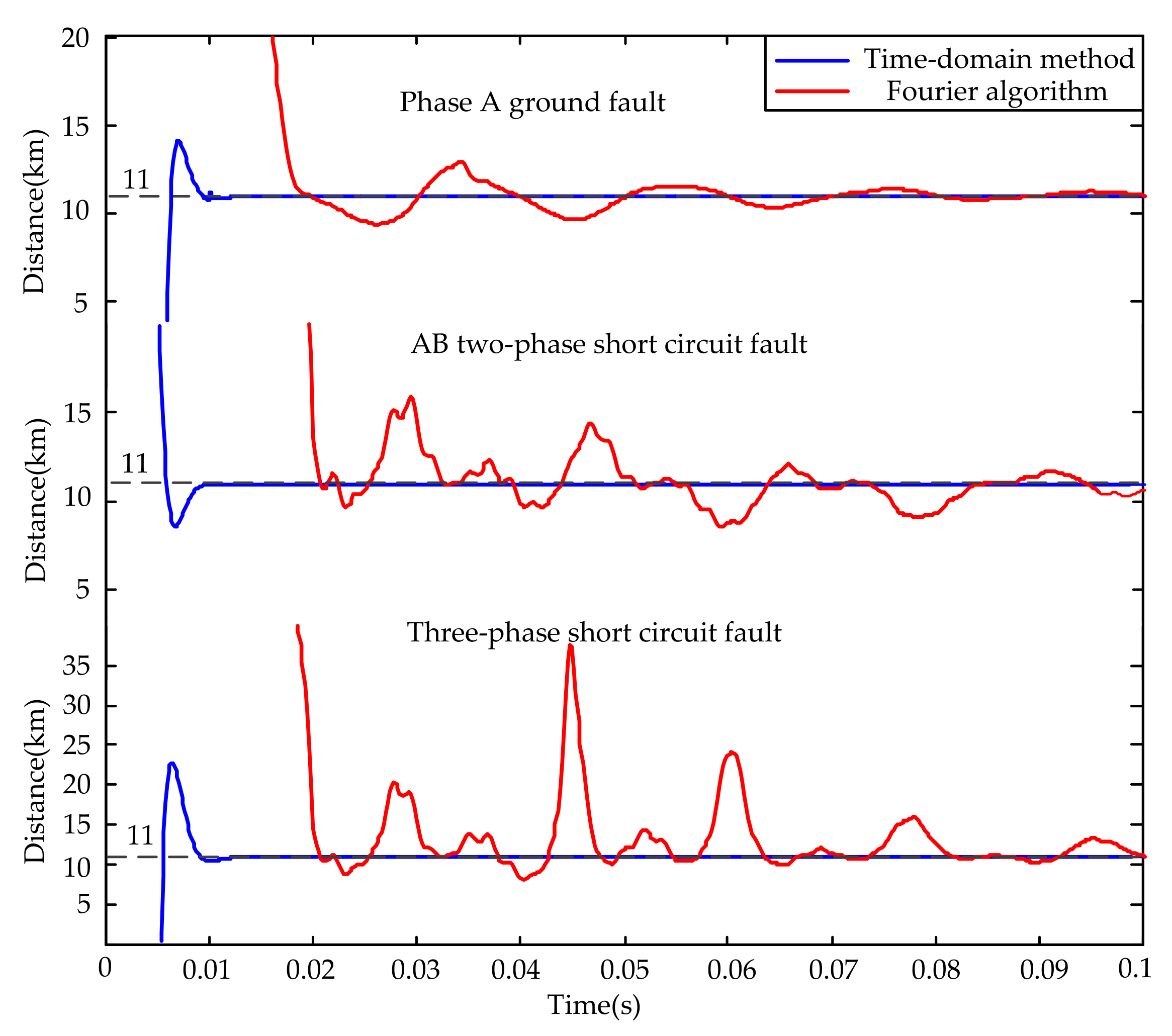
Table 1.
Performance of the time-domain method when faults occur.
| Fault Type | The Error of Fault Distance Measurement Result | ||
|---|---|---|---|
| 5 km | 10 km | 15 km | |
| Single-phase ground | 0.17% | 0.20% | 0.22% |
| Two-phase ground | 0.23% | 0.16% | 0.30% |
| Phase-to-phase short circuit | 0.04% | 0.63% | 0.03% |
| Three-phase short circuit | 0.07% | 0.18% | 0.03% |
Table 2.
Performance of the Fourier method when faults occur.
| Fault Type | The Error of Fault Distance Measurement Result | ||
|---|---|---|---|
| 5 km | 10 km | 15 km | |
| Single-phase ground | 3.67% | 3.38% | 3.11% |
| Two-phase ground | 3.27% | 3.13% | 2.94% |
| Phase-to-phase short circuit | 7.24% | 7.64% | 7.29% |
| Three-phase short circuit | 26.39% | 26.07% | 25.71% |
© 2018 by the authors. Licensee MDPI, Basel, Switzerland. This article is an open access article distributed under the terms and conditions of the Creative Commons Attribution (CC BY) license (http://creativecommons.org/licenses/by/4.0/).
Share and Cite
MDPI and ACS Style
Li, B.; Liu, J.; Wang, X.; Zhao, L. Fault Studies and Distance Protection of Transmission Lines Connected to DFIG-Based Wind Farms. Appl. Sci. 2018, 8, 562. https://doi.org/10.3390/app8040562
AMA Style
Li B, Liu J, Wang X, Zhao L. Fault Studies and Distance Protection of Transmission Lines Connected to DFIG-Based Wind Farms. Applied Sciences. 2018; 8(4):562. https://doi.org/10.3390/app8040562
Chicago/Turabian StyleLi, Bin, Junyu Liu, Xin Wang, and Lili Zhao. 2018. "Fault Studies and Distance Protection of Transmission Lines Connected to DFIG-Based Wind Farms" Applied Sciences 8, no. 4: 562. https://doi.org/10.3390/app8040562
Note that from the first issue of 2016, this journal uses article numbers instead of page numbers. See further details here.