Article

Thermally Bonded PET–Basalt Sandwich Composites for Heat Pipeline Protection: Preparation, Stab Resisting, and Thermal-Insulating Properties

1
Innovation Platform of Intelligent and Energy-Saving Textiles, School of Textiles, Tianjin Polytechnic University, Tianjin 300387, China
2
Fujian Key Laboratory of Novel Functional Fibers and Materials, Minjiang University, Fuzhou 350108, China
3
Graduate Institute of Biotechnology and Biomedical Engineering, Central Taiwan University of Science and Technology, Taichung 40601, Taiwan
4
Laboratory of Fiber Application and Manufacturing, Department of Fiber and Composite Materials, Feng Chia University, Taichung 40724, Taiwan
5
Department of Fashion Design, Asia University, Taichung 41354, Taiwan
6
School of Chinese Medicine, China Medical University, Taichung 40402, Taiwan
*
Author to whom correspondence should be addressed.
Appl. Sci. 2018, 8(4), 510; https://doi.org/10.3390/app8040510
Submission received: 6 February 2018 / Revised: 20 March 2018 / Accepted: 26 March 2018 / Published: 27 March 2018

Abstract

:
In order to solve the cost and bulky problems of buried thermal pipeline insulating materials, this study adopts basalt fabric and low-melting PET nonwoven to construct low-cost and light-weight pipeline thermal-insulating composites after needle punching and thermal bonding processes. Research result shows that thermal-bonded temperature affected the stab resistance and burst energy more significantly. As thermal-bonded temperature increased, knife resistance and spike resistance presented the upward and then downward trends, but the burst energy gradually decreased. Yarn pull-out result shows that the enhancement of stab resistance of intra-/inter-thermal-bonded structure resulted from the increment in the coefficient of friction between yarns. When PET–basalt sandwich composites were thermal-bonded at 140 °C for 5 min, the maximum knife and spike resistance were 147.00 N (1.99 J) and 196.30 N (1.11 J), respectively, and burst energy was 4.79 J, thermal conductivity reduced to 0.0073 W/(m∙K). The resultant thermally bonded sandwich composites can be used as thermal-insulating protection for buried thermal pipeline.

1. Introduction

With the quickened progress of urbanization, the ground space becomes more and more constrained. Thermal pipelines buried to transport thermal energy are increasingly common. However, in the transportation of hot water and steam, long transmission distance results in thermal energy consumption [1]. Most available thermal pipeline insulation on the market are commonly light calcium silicate, rock wool, aluminium silicate, and polyurethane, and thermal conductivity is about 0.053, 0.052, 0.036, and 0.018~0.024 w/(m∙k) [2]. However, most of these materials are rigid and hard-processable, and mineral fibers are harmful to the human body. Moreover, polyurethane foam has brittle cells, where unstable volume affects the service life and quality of thermal pipeline. Therefore, thermal pipeline insulation materials that are harmless and with high thermal insulation have been focused on in the studies. Under this background, thermal insulating composites completely made of fibers are proposed.
As an inorganic fiber, basalt fiber has good strength, modulus, better strain to failure, high thermal insulation, good chemical resistance, are easily processed, eco-friendly, and inexpensive [3,4,5,6,7,8]. Moreover, nonwoven technology produces a fibrous porous structure that stores static air and also can form a more compact structure by carrying the surficial fibers into the interlayers. All these can be beneficial to increment in thermal insulation. As reported by researchers, fibrous thermal insulating nonwovens can be affected by fiber diameter, volume fraction, fiber conductivity, and fiber radiation [9,10,11]. Mohammadi et al. indicated that affecting parameters of the thermal insulation model include fabric weight, thickness, porosity, and structure, along with the applied temperature [12]. Based on these, thermal-bonded temperature and time of low-melting point affected the porosity and structure of the resultant composites. Besides this, thermal pipeline insulation materials are also subjected to sharp-objected damages when buried in the soil. Therefore, the sandwich composites structure proposed in this study has superiority in low cost, thermal insulating, and resisting against the diversified mechanical failures from knife, spike, and burst-shaped weapons. In this study, we will focus on discussing the influences of hot-baking temperature and time on quasi-static knife resistance, spike resistance, and burst strength of sandwich composites, which are made by low-melting PET nonwoven as well as basalt fabric, and reinforced by needle punching and thermal bonding. Moreover, the reason for enhancement of stab resistance is interpreted by yarn pull-out test [13,14,15]. Thermal insulating performance of sandwich composites is also explored.

2. Experimental Section

2.1. Materials and Methods

Low-melting point nonwoven (LPET nonwoven) purchased from Hsinnjy Nonwoven Limited Liability Company, Taichung, Taiwan) has an areal density (AD) of 400 g/m2, and a fiber fineness of 4 Denier (D). The maximum hot-resistance temperature and melting enthalpy of LPET nonwoven are 254.5 °C and 0.8707 mW/mg as displayed in Figure 1. Basalt plain fabric (BF fabric, Chin Carbon Fiber Technology Co., Ltd., Yixing, China) has a warp density of 50 counts/10 cm, a weft density of 49 counts/10 cm, and AD of 251 g/m2.
Two surface layers of LPET nonwoven fabrics and one interlayer of basalt plain woven fabric (BF) are laminated and needle punched using a RSZ-80 needle punching machine (Romseen Non-woven Machinery, Changshu, China). The triangular felting needle is 15 × 16 × 25 × 3 1/2 M332 G 53017 (Groz-Beckert, Baden-Wuerttemberg, Germany) with a total length of 3.5 inch as well as two of needle edges with three barbs and one of edges with two barbs in medium arrangement. Needle density is 150 needles/cm2, and needle depth is 6.5 mm according to our previous research results [16]. The laminated sandwich composites are thermally treated at different temperature (100, 120,140, 160 °C) and time (1, 5, 10, 15 min) within a self-made hot-baking mould. The structure of PET–BF sandwich composites is shown in Figure 2. The processing parameters and specifications of all samples are displayed in Table 1.

2.2. Measurements

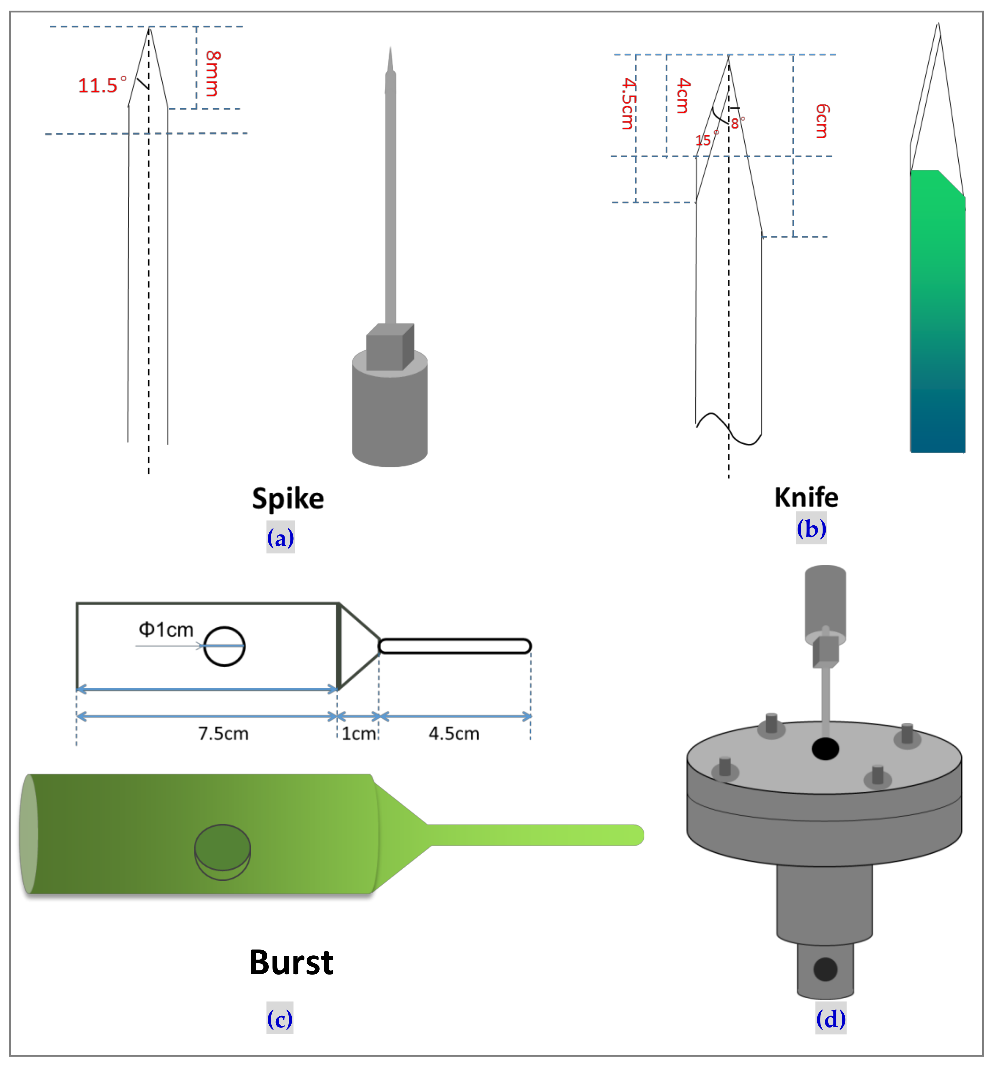
The quasi-static stab resistances of samples are measured at 508 mm/min using a computer servo control material testing machine (HT-2402, HungTa Intrument Co., Ltd., Taichung City, Taiwan) as specified in ASTM F1342-05 [17]. The testing heads have two types, including spike head and knife head, as shown in Figure 3a,b. The testing environmental temperature is 23 °C and the relative humidity is 53%. Samples have a size of 100 mm × 100 mm. Six samples for each specification are used for the test. The burst property of samples is tested at 100 mm/min using a computer servo control material testing machine (HT-2402, HungTa Intrument Co., Ltd., Taichung City, Taiwan) as specified in ASTM D3787 [18]. The specification of burst head is displayed in Figure 3c. The sample has a size of 150 mm × 150 mm. Five samples for each specification are used for this test. An example of installation diagram of spike head is displayed in Figure 3d, the same as that of knife head and burst head.
The yarn pull-out test of samples is tested at 100 mm/min using a computer servo control material testing machine (HT-2402, HungTa Instrument Co., Ltd., Taichung City, Taiwan). The samples have a size of 100 mm × 100 mm. The 40 mm-length free ends of yarns are reserved for the clamp between upper fixtures. Three samples for each specification are repeatedly measured. The sample fixtures of yarn pull-out test are shown in Figure 4.
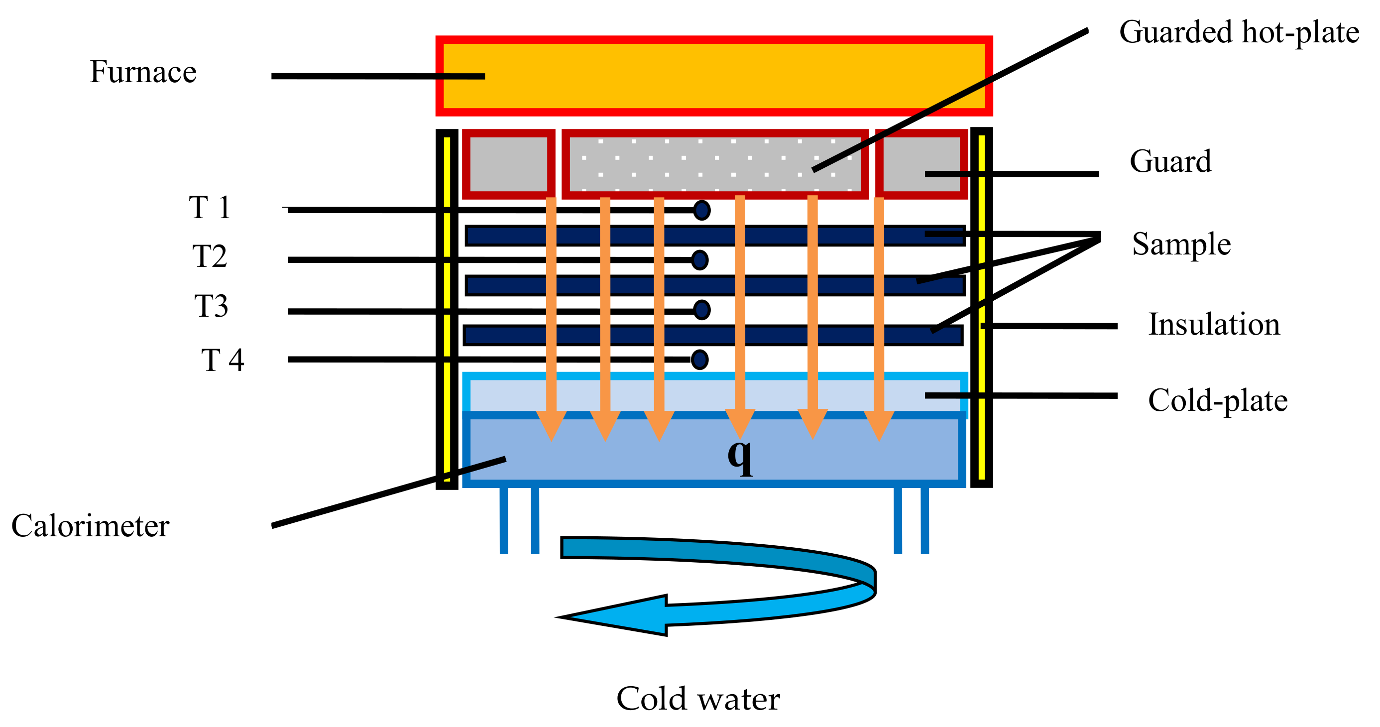
Thermal insulation of samples is measured by a DXR-I-SPB thermal conductivity tester (Xiangtan Huafeng Equipment Manufacture Co. Ltd., Xiangtan, China) as specified in ASTM C177 [19]. The hot plate temperature is set as 100 °C and 150 °C based on ASTM C1058. Samples have size of 200 mm × 200 mm. Three samples for each specification are tested for the mean value of thermal conductivity. The testing apparatus is displayed in Figure 5, and thermal conductivity is calculated as follows:
q = m ( t 2 t 1 ) C L = λ A ( T 2 T 1 )
λ = m ( t 2 t 1 ) C L A ( T 2 T 1 )
where q is heat flow, A is area, L is thickness, T1 is cold-plate temperature, T2 is hot-plate temperature, m is average flow of cold water in center calorimeter, C is water specific heat capacity (4.2 × 10³ J/kg), and t1 and t2 are respectively inlet temperature and outlet temperature of cold water.

3. Results and Discussion

3.1. Effects of Thermal-Bonded Time and Temperature on Knife Stab Resistance

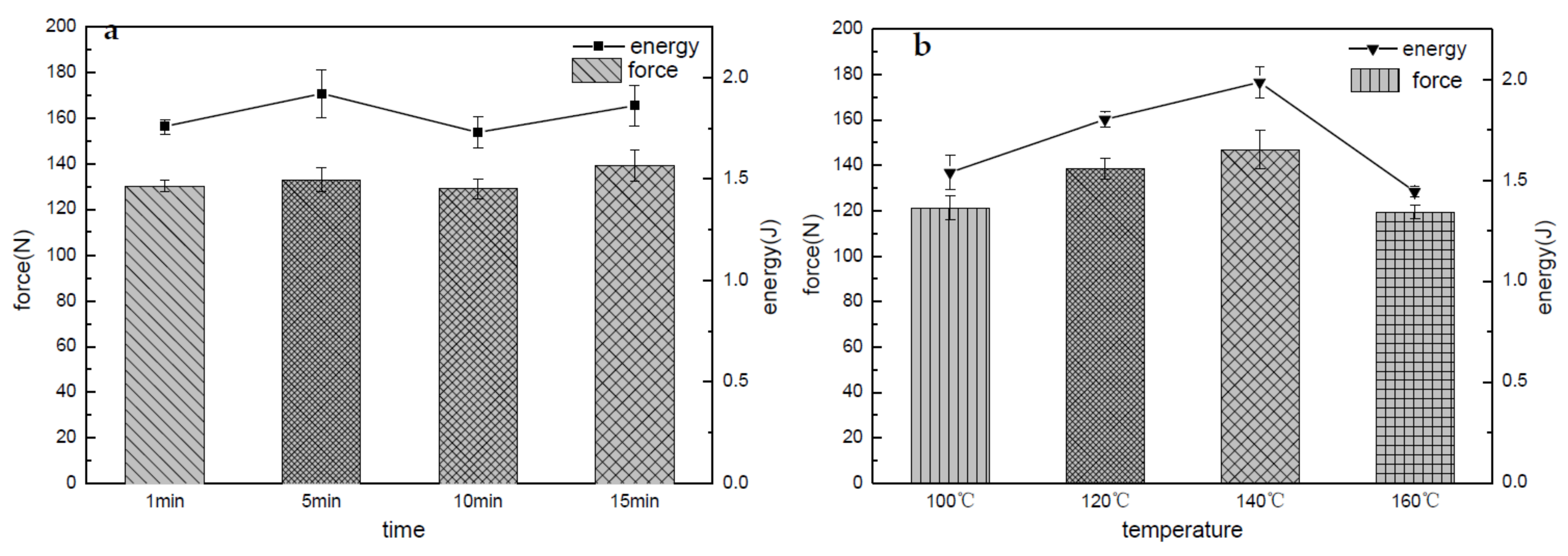
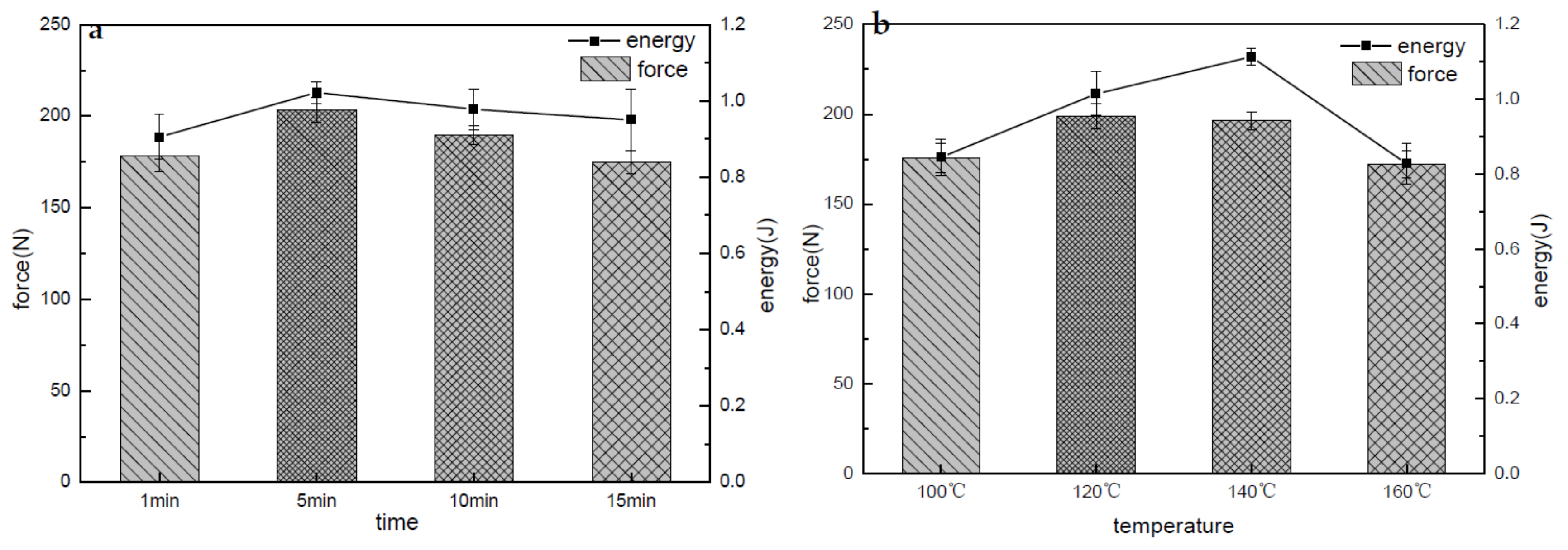
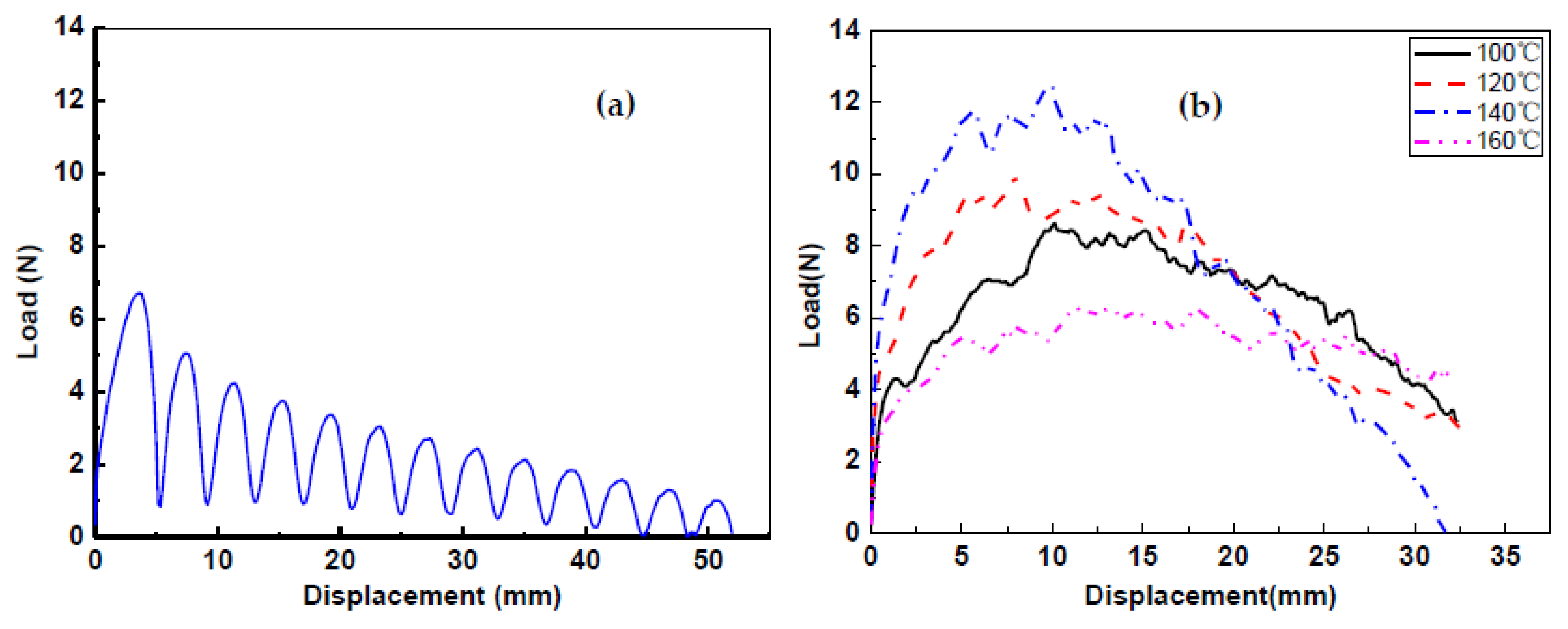
Figure 6a,b shows the knife stab resistances with different thermal-bonded time and temperature. The hot-baking time is changed as 1, 5, 10, and 15 min when the sandwich composites are thermally treated at 120 °C. The hot-baking temperature is varied as 100, 120, 140, and 160 °C when the composites are thermally treated for 5 min. Comparatively, knife-resistance force and energy of thermal treatment for 5 min are larger than other thermal durations, which represents the best knife-resistance performance. Under the action of knife, surficial nonwoven and interlayer BF are both damaged, and the failure surface presents a thin and long cut, which results from the cutting, friction between yarns, and friction between knife and yarns, as well as tensile plastic deformation [20]. The higher friction coefficient between yarns can generate a larger knife-resistance load and energy [21]. With shorter hot-baking time, the effect of plastic deformation to knife resistance is bigger than the yarn slippage and friction between knife and surface of composites. After longer hot-baking time, LPET fibers are thermally bonded with each other. The plastic deformation becomes smaller, and the friction between knife and composites exhibits to be greater. However, the contributions of plastic deformation and friction to the sandwich composites were distinct at different thermally bonded time; therefore, 5 min showed the maximum knife energy as presented in Figure 6a. With higher temperature, the knife force and energy both firstly increase and then decrease as seen in Figure 6b. This is because heat transmission needs a certain duration; at lower temperature the interlayer LPET fibers cannot melt completely, but at much higher temperature, all LPET fibers in the composite reached melting points, and fiber structure was completely damaged, which produced the smallest plastic deformation and lower knife energy. Comprehensively speaking, thermal bonding at 140 °C possesses the biggest knife-resistance force and energy.
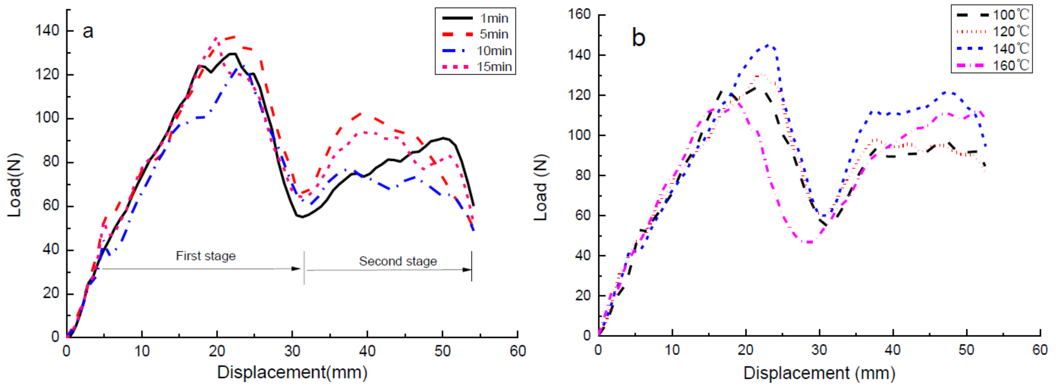
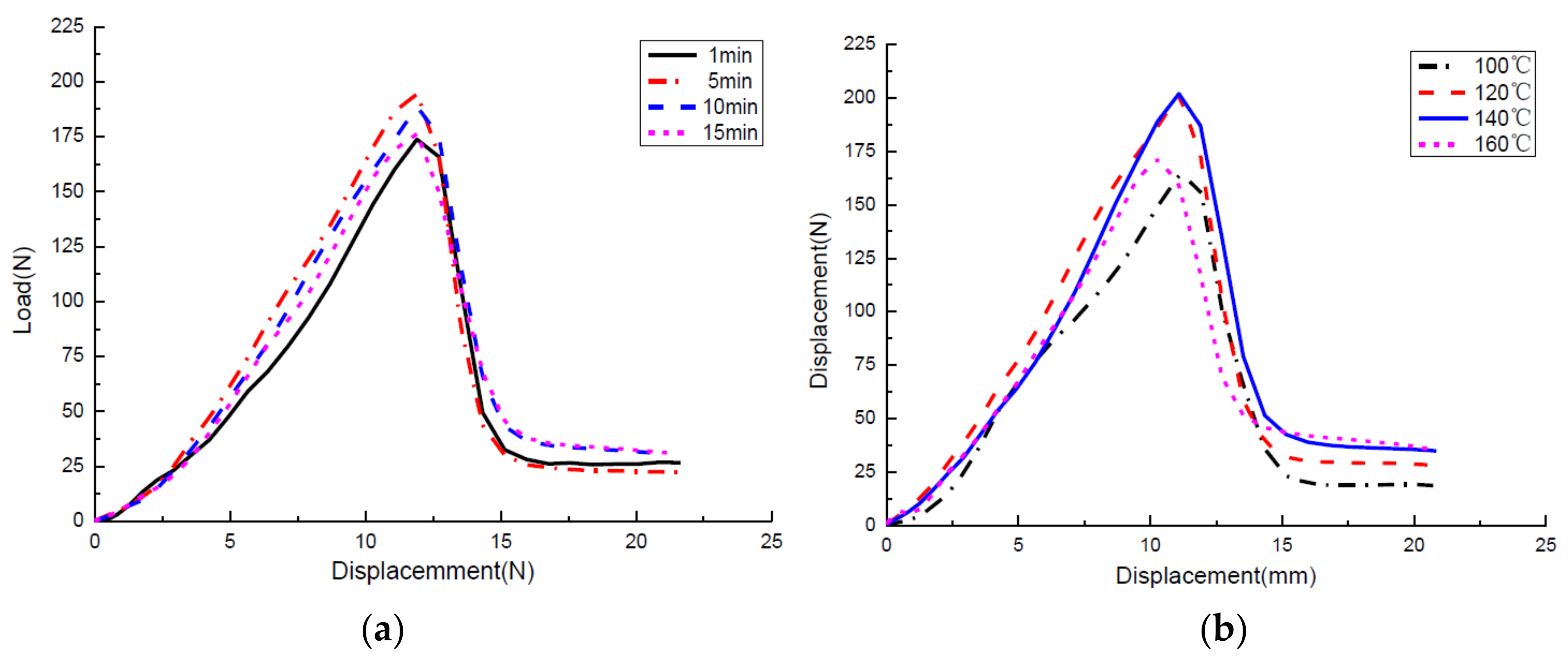
Typical knife displacement–load curves with different thermal-bonded time and temperature are reported in Figure 7. Two sets of data with different time and temperature are similar. They are both divided into two steps. The first stage is due to the fibers cutting and friction force between knife head and composites. In this stage, the knife firstly slides apart the fibers and then cuts the original contacting regions of fibers. It can been seen from Figure 6a,b that the fibers separation becomes more difficult at higher temperature and longer time, which results in an obvious first peak in the first stage. The maximum peak occurs when the original contacting fibers are cut. As the knife penetrated deeply, the cutting fibers and friction between cutting fibers continuously increased, which in turn increased the knife-resistance force.

3.2. Effects of Thermal-Bonded Time and Temperature on Spike Stab Resistance

Figure 8 shows the spike-resistance results of sandwich composites. Figure 8a displays the spike-resistance force and energy at 120 °C for different thermal-bonded time, and Figure 8b reveals those at different temperature for 5 min. Both of them exhibit the climbing up and then down trends with increase in thermal-bonded temperature and time. This demonstrated the double-sided effects of thermal bonding. At higher temperature or longer time, the thermal-bonded area became bigger, leading to more compact structure in composites. However, when surpassing a certain value, completely melting LPET fibers make the composite brittle and breaking elongation small. These changes reduced the friction and deformation between spike head and composites and then conversely decreased the spike resistance [22]. The maximum spike-resistance force and energy is 196.3 N and 1.11 J when PET–BF composites were thermally bonded at 140 °C for 5 min.
Figure 9 displays the typical spike-resistance curves of PET–BF sandwich composites. The spike depressed the surface of whole composites as displacement increases. At the moment that compression deformation energy reaches the maximum and the friction changes from static friction to dynamic friction, the spike resistance achieves the maximum value [23]. This accords with our previous study, which indicated that the friction was the main mechanism for spike resistance [24]. Therefore, even with varying temperature and time, the spike resistance responds in similar behaviors.

3.3. Effects of Thermal-Bonded Time and Temperature on Burst Property

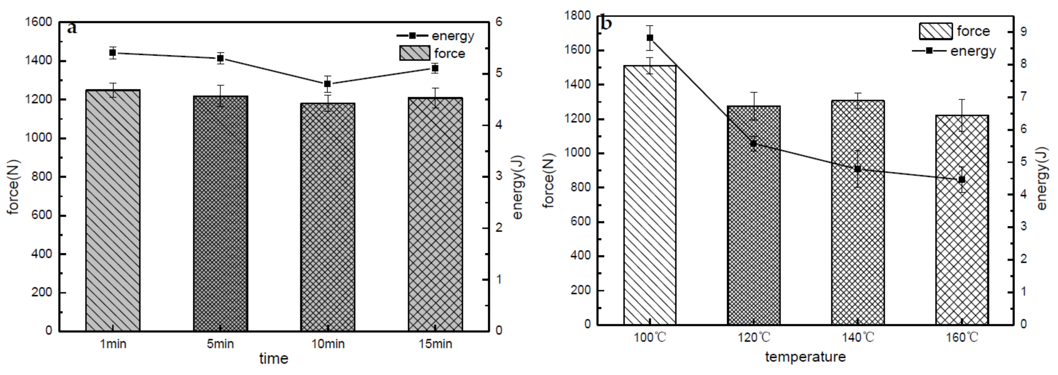
Figure 10 shows bursting strength and energy of PET–BF sandwich composites. Different from knife and spike experimental results, bursting strength and energy both decrease with thermal-bonded temperature (see Figure 10b). This is because the burst failure mode was yarn pull-out, fracture, and nonwoven deformation, not the same as stab resistance, as indicated by Yan et al. [25]. However, being thermal-bonded at 120 °C, 10 min duration reveals the minimum burst energy. This decrease of burst energy has no significance in the influence of temperature to burst energy. It reflects that thermal-bonded temperature affected burst energy more significantly than time. The maximum burst strength and energy happen at 100 °C for 5 min, reaching 1511.25 N and 8.82 J, respectively, when sandwich composites generate the maximum deformation.

3.4. Effect of Thermal-Bonded Temperature on Yarn-Out Force

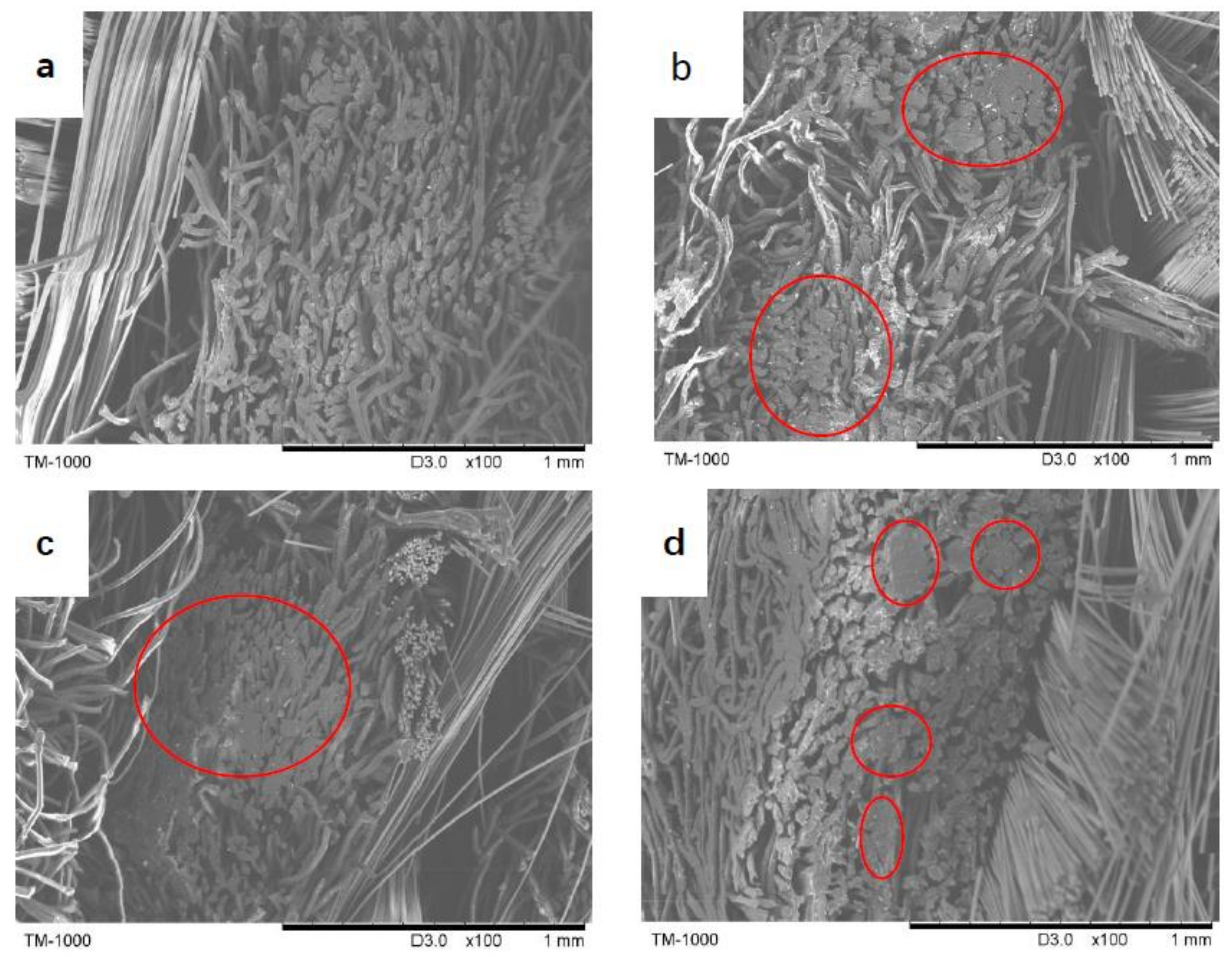
In order to deeply study on effect of thermal-bonded temperature on the stab resistance and burst property, the fracture planes of sandwich composites after knife damage are observed in Figure 11 using Tabletop Microscope 1000 (Hitachi, Japan). It can be seen from Figure 11a that when composites were thermally bonded at 100 °C, most of the fiber ends generated cut deformation and remained in the fiber state. As thermal-bonding temperature increased from 120 °C to 140 °C, thermal-bonding area became bigger and thermal-bonding points distributed uniformly, as seen in the red circles in Figure 11b,c. When composites were thermal-bonded at 160 °C, LPET lost their fiber shape, and conversely, a relatively bigger void was found, which can explain the decreased tendency of knife resistance and spike resistance as function of thermal-bonded temperature in Figures 6b and 8b. Thermal-bonding points can increase the fibers cohesion and decrease the inter-fiber slippage, which is beneficial to improve the stab resistances and their stability [26]. However, when surpassing the melting point, the composites’ excessive shrinkage conversely produced a large number of voids after hot-baking, which in turn decreases the stab resistance.
The tendency of yarn pull-out force also follows the same with varying temperatures as shown in Figure 12. Compared to pure basalt fabric, the yarn pull-out force at 140 °C is increased by one time. Using an approach similar to Coulomb friction, f = μF, the pull-out force (f) is proportional to coefficient of friction (μ) at the same applied pre-load perpendicular to the pull-out force (F). Therefore, higher pull-out force corresponded to the bigger coefficient of friction. Figure 12 shows the static and dynamic forces of friction as related to displacement. Figure 12a displays significant static and kinetic friction forces, but Figure 12a reveals that the kinetic friction force becomes insignificant because vertical needle-bonded points and thermal-bonded points limited the pull-out displacement of basalt yarns. The slopes of pull-out force after thermal-bonding at 100 °C, 120 °C, 140 °C, and 160 °C are 5.63, 4.36, 9.19, and 4.25, respectively, which shows the bonding effects from vertical tufts and thermal-bonding points and thus explains the tendency of spike and knife resistance in relation to thermal-bonded temperature.

3.5. Effect of Thermal-Bonding Temperature on Thermal Conductivity

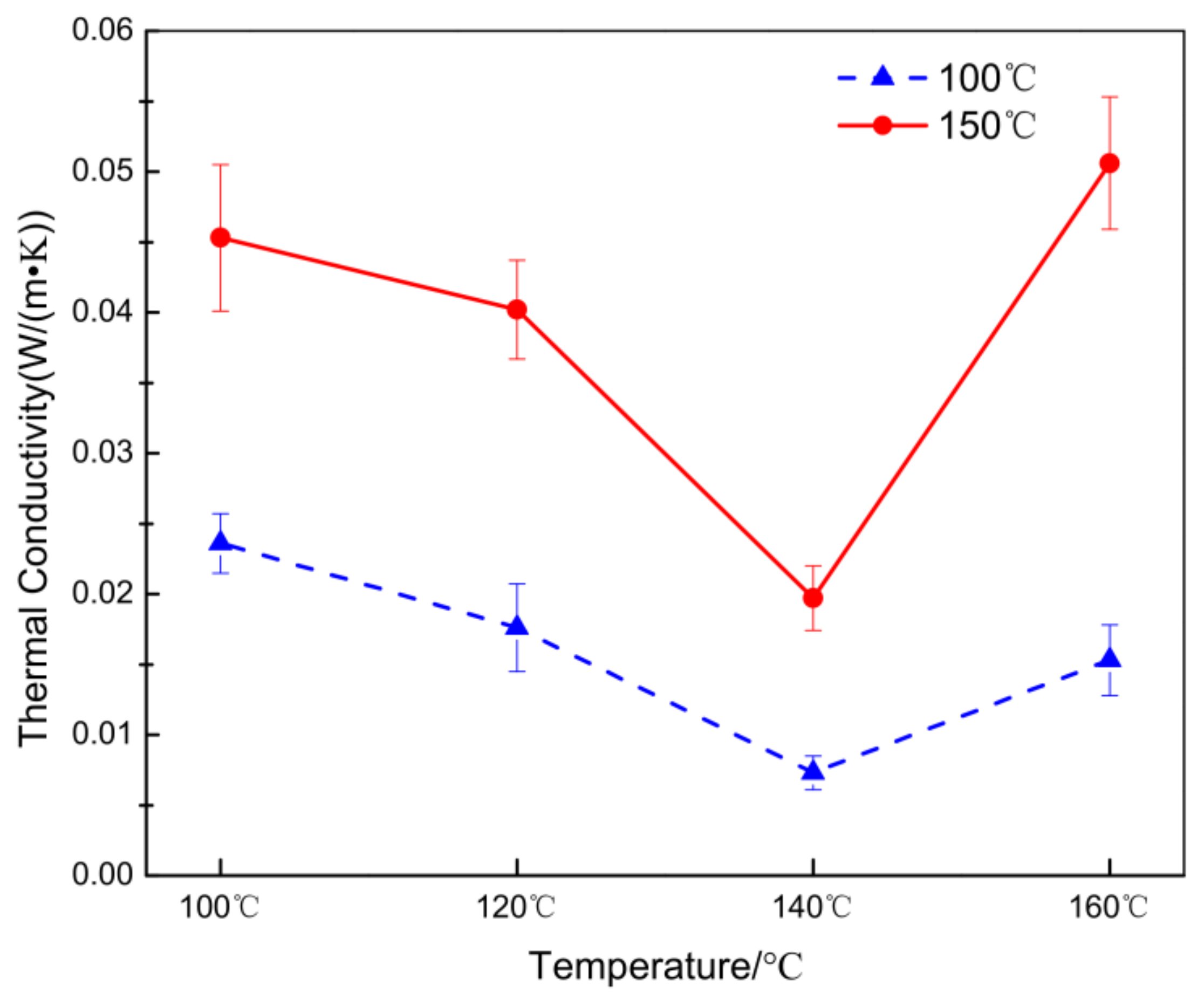
Figure 13 shows thermal conductivity results at 100 °C and 150 °C after composites were thermally bonded at different temperatures. As thermal-bonded temperature increases, thermal conductivity at 100 °C and at 150 °C firstly decreases and then increases. This is due to the number and size of air voids reduced air convection in composites. After thermal shrinkage and bonding, melting LPET fibers can lock some static air in the LPET nonwoven and interspace between basalt fabrics, which decreased the thermal convection. Meanwhile, static air had the lowest thermal conductivity Ka, 0.0243 W/(m·K), and the larger air volume fraction Va results in lower thermal conductivity Km in accordance with simple mix principle as Km= VfKf + VaKa (where Vf is fiber volume fraction, Kf is fiber thermal conductivity). This finding corresponds to the results indicated by Lin et al. that air convection decreased with void size in the structure. Thermal conductivities of resultant composites were all below 0.0250 W/(m·K) at testing temperature of 100 °C, much smaller than that of PET–LPET nonwoven indicated in the above-mentioned study [27]. Comparatively, increasing testing temperature to 150 °C, thermal conductivity increased to 0.0197 W/(m·K) when composites were thermally bonded at 140 °C which due to higher thermal conductivity of fibers [28].

4. Conclusions

This study designed an intra-/inter- reinforced PET–Basalt sandwich composite structure based on the thermal bonding and needle punching process, which is used for thermal pipeline protection. Effects of thermal-bonding parameters including temperature and time on knife resistance, spike resistance, and burst property were investigated, and effect of thermal-bonded temperature on yarn pull-out forces was explored to explain the influencing mechanism. Thermal conductivity of all samples was also discussed.
Stab resistance results showed that thermal-bonded temperature had more significant effect on both of knife-resistance and spike-resistance energy than thermal-bonded time. Moreover, the knife- and spike-resistance energy showed an increase and then decrease with increasing thermal-bonded time, but the burst energy steadily decreased. This difference is due to the different failure damage mechanisms. Yarn pull-out force results displayed that the tends of thermal-bonded temperature on pull-out force corresponded to those on knife and spike resistances. Moreover, the reason for increase of stab resistance from thermal-bonded temperature was due to higher coefficient of friction between yarns. Thermal conductivity showed that the lowest thermal conductivity was 0.0073 W/(m·K) at setting temperature of 100 °C. According to the stab resistance, burst property, and thermal insulation, the resultant sandwich composites can be used for thermal insulation of pipeline in the future.

Acknowledgments

The authors gratefully acknowledge the financial support provided by the National Natural Science Foundation of China (grant numbers 51503145, 11702187, 11502163), and the Open Project Program of Fujian Key Laboratory of Novel Functional Fibers and Materials (Minjiang University), China (No. FKLTFM 1704, FKLTFM1722 and FKLTFM1718). This study is also supported by the Natural Science Foundation of Tianjin (grant numbers 17JCQNJC03000, 16JCZDJC36600) and the Open Project Program of High-Tech Organic Fibers Key Laboratory of Sichuan Province (grant numbers PLN2016-07).

Author Contributions

In this study, the concepts and designs for the experiment, required materials, as well as processing and assessment instrument were supervised by Jia-Horng Lin and Ching-Wen Lou. Experiment and data analysis were conducted by Xiayun Zhang. Text composition and results analysis were performed by Ting-Ting Li. Photos were drawn by Wenna Dai. The experimental results were examined by Haokai Peng and Qian Jiang.

Conflicts of Interest

The authors declare no conflict of interest.

References

  1. Zaki, G.M.; Al-Turki, A.M. Optimization of multilayer thermal insulation for pipelines. Heat Transf. Eng. 2000, 21, 63–70. [Google Scholar]
  2. Guo, F. Selection of heat insulation materials for thermal pipeline and analysis of problems. Shanxi Arch. 2017, 43, 196–197. (In Chinese) [Google Scholar]
  3. Hao, L.C.; Yu, W.D. Evaluation of thermal protective performance of basalt fiber nonwoven fabrics. J. Therm. Anal. Calorim. 2010, 100, 551–555. [Google Scholar] [CrossRef]
  4. Wei, B.; Cao, H.L.; Song, S.H. Degradation of basalt fibre and glass fibre/epoxy resin composites in seawater. Corros. Sci. 2011, 53, 426–431. [Google Scholar] [CrossRef]
  5. Subagia, I.A.; Kim, Y.; Tijing, L.D.; Kim, C.S.; Shon, H.K. Effect of stacking sequence on the flexural properties of hybrid composites reinforced with carbon and basalt fibers. Compos. Part B Eng. 2014, 58, 251–258. [Google Scholar] [CrossRef]
  6. Rambo, D.A.S.; de Andrade Silva, F.; Toledo Filho, R.D.; Ukrainczyk, N.; Koenders, E. Tensile strength of a calcium-aluminate cementitious composite reinforced with basalt textile in a high-temperature environment. Cem. Concr. Comp. 2016, 70, 183–193. [Google Scholar] [CrossRef]
  7. Bakare, F.O.; Ramamoorthy, S.K.; Åkesson, D.; Skrifvars, M. Thermomechanical properties of bio-based composites made from a lactic acid thermoset resin and flax and flax/basalt fibre reinforcements. Compos. Part A Appl. 2016, 83, 176–184. [Google Scholar] [CrossRef]
  8. Ahmad, Z.; Sirková, B.K. Tensile behavior of Basalt/Glass single and multilayer-woven fabrics. J. Text. Inst. 2017, 1–9. [Google Scholar] [CrossRef]
  9. Wu, H.J.; Fan, J.T.; Du, N. Thermal energy transport within porous polymer materials: Effects of fiber characteristics. J. Appl. Polym. Sci. 2007, 106, 576–583. [Google Scholar] [CrossRef]
  10. Fan, J.; Cheng, X.; Wen, X.; Sun, W. An improved model of heat and moisture transfer with phase change and mobile condensates in fibrous insulation and comparison with experimental results. Int. J. Heat Mass Tranf. 2004, 47, 2343–2352. [Google Scholar] [CrossRef]
  11. Zhu, F.L.; Li, K.J. Determining effective thermal conductivity of fabrics by using fractal method. Int. J. Thermophys. 2010, 31, 612–619. [Google Scholar] [CrossRef]
  12. Mohammadi, M.; Banks-Lee, P.; Ghadimi, P. Determining effective thermal conductivity of multilayered nonwoven fabrics. Text. Res. J. 2003, 73, 802–808. [Google Scholar] [CrossRef]
  13. Hasanzadeh, M.; Mottaghitalab, V.; Babaei, H.; Rezaei, M. The influence of carbon nanotubes on quasi-static puncture resistance and yarn pull-out behavior of shear-thickening fluids (STFs) impregnated woven fabrics. Compos. Part A Appl. Sci. Manuf. 2016, 88, 263–271. [Google Scholar] [CrossRef]
  14. Kordani, N.; Vanini, A.S.; Amiri, H. Numerical solution of penetration into woven fabric target impregnated with shear thickening fluid. Polym. Polym. Compos. 2016, 24, 281–287. [Google Scholar]
  15. Majumdar, A.; Laha, A. Effects of fabric construction and shear thickening fluid on yarn pull-out from high-performance fabrics. Text. Res. J. 2016, 86, 2056–2066. [Google Scholar] [CrossRef]
  16. Li, T.T.; Zhang, X.; Wu, L.; Peng, H.; Lou, C.W.; Lin, J.H. PET/Basalt stab resistant composite fabrics based on box-behnken design: Parameter optimization and empirical regression model. J. Sandw. Struct. Mater. 2018; in press. [Google Scholar]
  17. ASTM F1342. Standard Test Method for Protective Clothing Material Resistance to Puncture; ASTM International: West Conshohocken, PA, USA, 2005. [Google Scholar]
  18. ASTM D3787. Standard Test Method for Bursting Strength of Textiles-Constant-Rate-of-Traverse (CRT) Ball Burst Test; ASTM International: West Conshohocken, PA, USA, 2007. [Google Scholar]
  19. ASTM C 177. Test Method for Steady-State Heat Flux Measurements and Thermal Transmission Properties by Means of the Guarded-Hot-Plate Apparatus; ASTM International: West Conshohocken, PA, USA, 2013. [Google Scholar]
  20. Reiners, P.; Kyosev, Y.; Schacher, L.; Adolphe, D.; Küster, K. Experimental investigation of the influence of wool structures on the stab resistance of woven body armor panels. Text. Res. J. 2016, 86, 685–695. [Google Scholar] [CrossRef]
  21. Wang, L.; Zhang, S.; Gao, W.; Wang, X. FEM analysis of knife penetration through woven fabrics. CMES Comp. Model Eng. 2007, 20, 11–20. [Google Scholar]
  22. Li, T.T.; Wang, R.; Lou, C.W.; Lin, J.H. Evaluation of high-modulus, puncture-resistance composite nonwoven fabrics by response surface methodology. J. Ind. Text. 2013, 43, 247–263. [Google Scholar] [CrossRef]
  23. Yahya, M.F.; Ghani, S.A.; Salleh, J. Effect of impactor shapes and yarn frictional effects on plain woven fabric puncture simulation. Text. Res. J. 2014, 84, 1095–1105. [Google Scholar] [CrossRef]
  24. Li, T.T.; Wang, R.; Lou, C.W.; Lin, J.H. Static and dynamic puncture behaviors of compound fabrics with recycled high-performance Kevlar fibers. Compos. Part B Eng. 2014, 59, 60–66. [Google Scholar] [CrossRef]
  25. Yan, R.; Huang, S.Y.; Huang, C.H.; Hsieh, C.T.; Lou, C.W.; Lin, J.H. Effects of needle-punched nonwoven structure on the properties of sandwich flexible composites under static loading and low-velocity impact. J. Compos. Mater. 2017, 51, 1045–1056. [Google Scholar] [CrossRef]
  26. Bao, L.; Wang, Y.; Baba, T.; Fukuda, Y.; Wakatsuki, K.; Morikawa, H. Development of a high-density nonwoven structure to improve the stab resistance of protective clothing material. Ind. Health 2017, 55, 513–520. [Google Scholar] [CrossRef] [PubMed]
  27. Lin, C.M.; Lou, C.W.; Lin, J.H. Manufacturing and properties of fire-retardant and thermal insulation nonwoven fabrics with FR-polyester hollow fibers. Text. Res. J. 2009, 79, 993–1000. [Google Scholar] [CrossRef]
  28. Wang, T.; Liu, X.; Zhuang, M. Influence of environmental temperature on the thermal conductivity of fiber materials. Shanghai Text. Sci. Technol. 2014, 42, 6–9. (In Chinese) [Google Scholar]
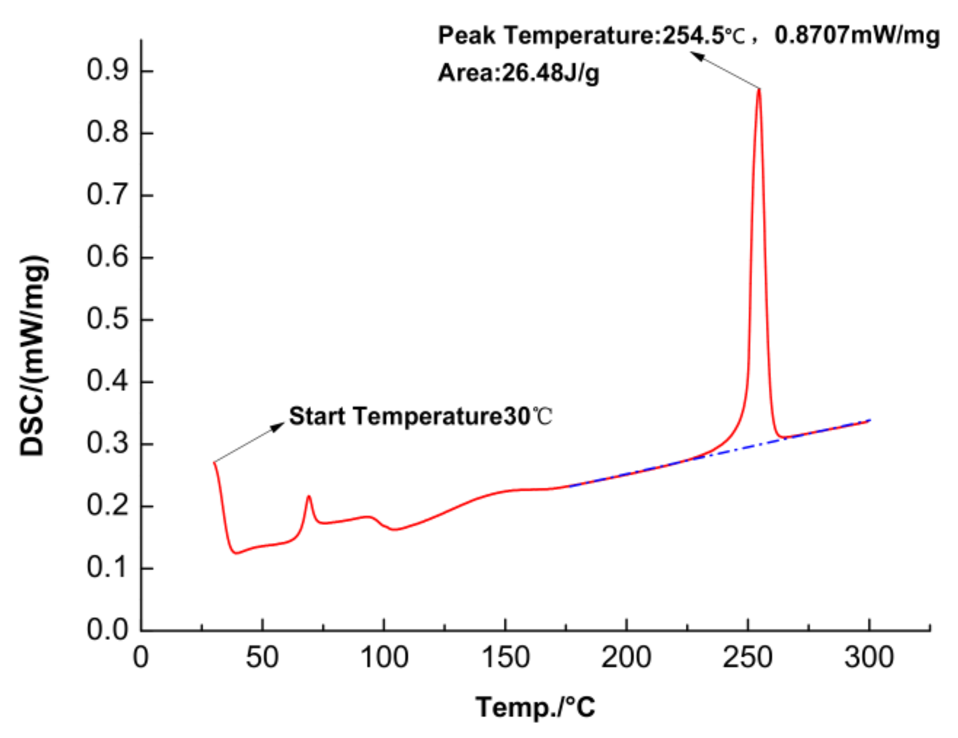
Figure 1. DSC curves of low-melting point nonwoven (LPET) nonwoven after heating at 10 °C/min from 30 °C to 300 °C.
Applsci 08 00510 g001
Figure 2. Structural diagram of sandwich composites which are composed of LPET nonwovens (upper and lower layer) and basalt plain fabric (BF fabric; interface layer) after needle punching and hot backing process.
Applsci 08 00510 g002
Figure 3. (ac) shows the quasi-static testing head for spike stab, knife stab, and burst, and (d) shows the examples of installation drawing of spike head.
Applsci 08 00510 g003
Figure 4. Yarn pull-out clamp of samples. (a) Model diagram of the clamp; (b,c) assembly and part pictures of practical clamp.
Applsci 08 00510 g004
Figure 5. The testing apparatus for thermal insulation.
Applsci 08 00510 g005
Figure 6. Knife-resistance force and energy of sandwich composites with different (a) hot-baking time and (b) hot-baking temperature.
Applsci 08 00510 g006
Figure 7. Typical knife-resistance curves of composites thermal-bonded at (a) different time and (b) different temperature.
Applsci 08 00510 g007
Figure 8. Spike-resistance force and energy of PET–BF sandwich composites after thermal-bonding at different time (a) and temperature (b).
Applsci 08 00510 g008
Figure 9. Typical spike-resistance curves of composites thermal-bonded at different time (a) and different temperature (b).
Applsci 08 00510 g009
Figure 10. (a) Burst force and (b) energy of PET–BF sandwich composites after thermal-bonding at different time and temperature.
Applsci 08 00510 g010
Figure 11. SEM observations of knife failure planes when composites were thermal-bonded at (a) 100 °C; (b) 120 °C; (c) 140 °C; and (d) 160 °C. The red circles show thermal-bonding region.
Applsci 08 00510 g011
Figure 12. Yarn pull-out force as function of crosshead displacement for (a) pure basalt fabric and (b) sandwich composites thermal-bonded at varying temperature.
Applsci 08 00510 g012
Figure 13. Thermal conductivity results at 100 °C and 150 °C of sandwich composites being thermal-bonded at different temperature.
Applsci 08 00510 g013
Table 1. The processing parameters and specifications of all samples.
Sample CodeTemperature (°C)Time (min)Thickness (mm)AD (g/m2)
110053.571050
212053.561050
314053.551050
416053.551050
512013.571050
612053.561050
7120103.551050
8120153.541050