Field Experiments to Evaluate Thermal Performance of Energy Slabs with Different Installation Conditions


1
School of Civil, Environmental and Architectural Engineering, Korea University, Seoul KS013, Korea
2
Department of Civil Engineering and Environmental Sciences, Korea Military Academy, Seoul KS013, Korea
*
Author to whom correspondence should be addressed.
Appl. Sci. 2018, 8(11), 2214; https://doi.org/10.3390/app8112214
Submission received: 29 September 2018
/
Revised: 29 October 2018
/
Accepted: 7 November 2018
/
Published: 10 November 2018
(This article belongs to the Special Issue Sciences in Heat Pump and Refrigeration)
Abstract
:The energy slab is a novel type of horizontal Ground Heat Exchanger (GHEX), where heat exchange pipes are encased in building slab structures. The thermal performance of energy slabs is usually inferior to the conventional closed-loop vertical GHEX because its installation depth is relatively shallow and therefore affected by ambient air temperature. In this paper, heat exchange pipes were made of not only conventional high-density polyethylene (HDPE), but also stainless steel (STS), which is expected to enhance the thermal performance of the energy slabs. In addition to a floor slab, a side wall slab was also used as a component of energy slabs to maximize the use of geothermal energy that can be generated from the underground space. Moreover, a thermal insulation layer in the energy slabs was considered in order to reduce thermal interference induced by ambient air temperature. Consequently, two different field-scale energy slabs (i.e., floor-type and wall-type energy slabs) were constructed in a test bed, and two types of heat exchange pipes (i.e., STS pipe and HDPE pipes) were installed in each energy slab. A series of thermal response tests (TRTs) and thermal performance tests (TPTs) were conducted to evaluate the heat exchange performance of the constructed energy slabs. Use of the STS heat exchange pipe enhanced the thermal performance of energy slabs. Additionally, the wall-type energy slab had a similar thermal performance to the floor-type energy slab, which infers the applicability of the additional use of the wall-type energy slab. Note that if an energy slab is not thermally cut off from the building’s interior space with the aid of thermal insulation layers, heat exchange within the energy slabs should be significantly influenced by fluctuations in ambient temperature.
1. Introduction
The Ground Source Heat Pump (GSHP) is a heating and cooling system that is usually coupled with the Ground Heat Exchanger (GHEX) to utilize geothermal energy. The GHEX allows the circulation of a working fluid through heat exchange pipes, which are buried underground with various arrangements, to induce heat exchange between the fluid and the surrounding ground. In general, a closed-loop vertical GHEX is a conventional type of GHEX, and is most popular in practice. However, the conventional closed-loop vertical GHEX incurs high initial investment costs because of a need for additional borehole drilling and extra construction area [1]. In particular, the drilling cost occupies more than 50% of the total construction cost. Therefore, to reduce the construction cost, novel types of GHEXs have been developed, which are fabricated in underground structure elements. For example, an energy textile (or tunnel) encases heat exchange pipes in a tunnel lining with a horizontal layout. Lee et al. (2012) and Zhang et al. (2014) conducted experimental studies on an energy textile with various arrangements [2,3], and compared the thermal performance indirectly with the conventional closed-loop vertical GHEX [2]. Zhang et al. (2013) developed an analytical solution for the energy textile, and verified their solution with field measurements [4]. An energy pile is another example that encases heat exchange pipes in a foundation pile [5,6,7,8,9,10,11,12,13]. Several studies have been conducted on thermal performance of energy piles [5,6,7], and a design method in the form of engineering charts has recently been developed [8]. Finally, an energy slab is installed as one component of floor slab layers to utilize a building structure as a hybrid energy exchanger [9]. Some experimental studies have been performed on the thermal performance of energy slabs [10,11,12]. If energy slabs are installed in a building along with conventional GHEXs, the construction cost can be economized by reducing the length of boring depth and the number of GHEXs. However, to the best of our knowledge, no comprehensive experimental studies have been conducted for enhancing the thermal performance of energy slabs or evaluating the effect of system parameters.
In general, increasing the thermal conductivity of surrounding media (such as ground formations, concrete slabs and heat exchange pipes) tends to improve the thermal performance of GHEXs. For example, increasing the thermal conductivity of grouting materials is suggested as an effective way to enhance the thermal performance of GHEXs [14,15]. However, in the case of energy slabs, it is difficult to change the material properties of concrete slabs, which encase heat exchange pipes, because it has to satisfy the structural requirements as a priority. Moreover, the thermal properties of ground formations should be predetermined by the construction condition. Therefore, increasing the thermal conductivity of heat exchange pipes can be an effective way to improve the thermal performance of energy slabs [16].
An energy slab is usually installed in the basement floor of buildings because such an underground environment may enhance their thermal performance, along with a relatively constant temperature throughout the year and the high thermal conductivity of ground formations. Moreover, in the underground space, the energy slab can be constructed not only on the floor, but also on the side wall in a basement, which can utilize the maximum thermal capacity of the ground and underground space more effectively. Even though an energy slab is constructed in the underground structure, the heat exchange pipes embedded in the concrete slab are closely adjacent to ambient air in the underground space, which causes thermal interference to the heat exchanger. Therefore, it is necessary to consider a thermal insulation layer in the energy slab to reduce thermal interference induced by ambient air temperature.
In this paper, experimental studies were carried out to investigate the thermal performance of energy slabs under different configurations. First, in addition to floor slabs, side walls were considered as a component of energy slabs. Second, a stainless steel (STS) pipe was considered as a heat exchange pipe, which is an alternative to a high-density polyethylene (HDPE) pipe that enhances the thermal performance of energy slabs. Consequently, two different field-scale energy slabs (i.e., floor-type and wall-type energy slabs) were constructed in a test bed, and two types of heat exchange pipes (i.e., STS and HDPE pipes) were installed in each type of energy slab. In addition, in the floor-type energy slabs, a thermal insulation layer was inserted in the energy slab to investigate its function by comparing it with another wall-type energy slab without the thermal insulation layer. Then, thermal response tests (TRTs) were conducted to indirectly compare the relative heat exchange efficiency of the energy slabs with different types of GHEXs. Moreover, thermal performance tests (TPTs) were performed to evaluate the thermal performance of the energy slabs.
2. Construction of the Energy Slab in a Test Bed
2.1. Configuration of the Energy Slabs
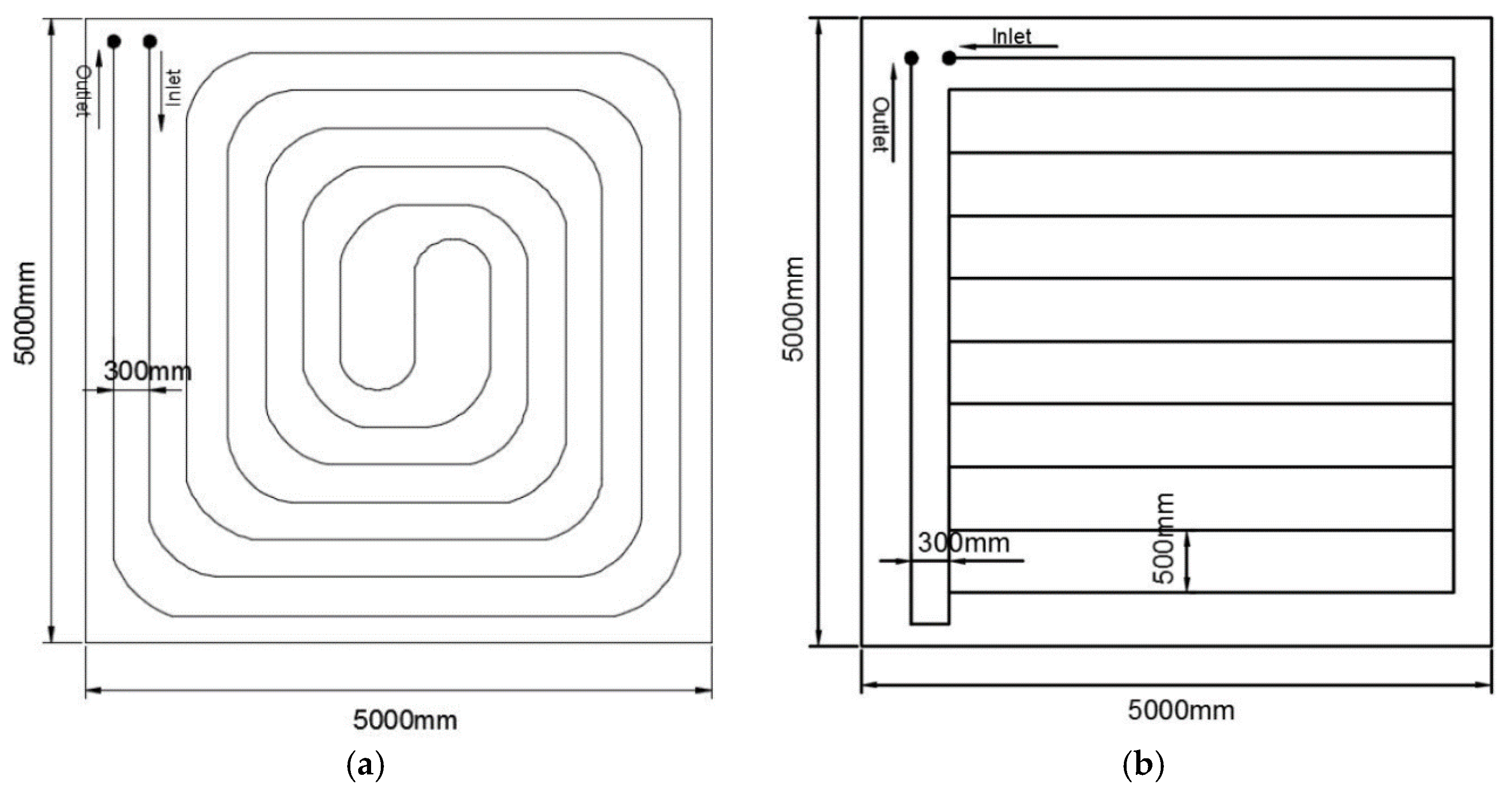
As the thermal conductivity of surrounding media increases, the thermal performance of GHEXs increases. Therefore, increasing the thermal conductivity of the surrounding media is one of the effective ways to enhance the thermal performance of GHEXs. However, it is challenging to significantly increase the thermal conductivity of ground formations and concrete slabs because they are predetermined according to the construction specification. Therefore, enhancing the thermal conductivity of heat exchange pipes is considered in this study. Field-scale energy slabs were constructed with the heat exchange pipes made of two different materials, i.e., HDPE and STS, to evaluate the effect of the pipe material on the thermal performance of energy slabs. Figure 1 shows the configuration of each pipe type. The HDPE pipe was spirally installed in the energy slab because it is difficult to make a small radius of curvature. Meanwhile, the STS pipe was arranged in a row because the STS pipe is pre-manufactured in a straight configuration. Then, the distance between adjacent pipes (i.e., 300 mm for the HDPE pipe and 500 mm for the STS pipe) was determined at the design stage so that the maximum length of pipe could be installed with consideration of the field conditions in the test bed.
Energy slabs can be constructed not only on the floor, but also on the side wall in a basement, which can utilize underground space more effectively. Therefore, both the floor-type and wall-type energy slabs were constructed in the test bed to compare the thermal performance of each type of energy slabs. Figure 2 shows a schematic description of the floor-type and wall-type energy slab in the test bed, and Table 1 summarizes the details of constructed energy slabs.
Figure 3 shows a sectional view of the constructed energy slab. Generally, as an energy slab is in operation, the temperature of concrete slabs continuously changes. Because the concrete slab is in contact with the ambient air in the underground space, temperature changes in the concrete slab can degrade the indoor heating, ventilation and air-conditioning (HVAC) efficiency. In contrast, the thermal performance of heat exchangers is reduced by the influence of the indoor air temperature. Conceptually, during heating/cooling operations, indoor air temperature of the underground space, which is maintained at the target heating/cooling temperature, is different from the working-fluid temperature within the heat exchange pipes. Heat exchange between the heat exchanger and ambient air can take place when no thermal insulation is equipped over the heat exchanger, which may reduce the thermal performance of heat exchangers. Therefore, a thermal insulation layer between the heat exchanger and ambient thermal environment should be arranged, to minimize such mutual influence. In the test bed, a phenol foam (PF) board with the thermal conductivity of 0.018 W/mK was adopted as a thermal insulation material, and exclusively installed in the floor-type energy slab. On the other hand, no thermal insulation layer was inserted in the wall-type energy slab. Temperature sensors were installed to monitor the temperature change of concrete slabs during the operation of energy slabs. The locations of temperature measurement are indicated as A and B in the wall-type energy slab, and A` and B` in the floor-type energy slab as shown in Figure 3.
2.2. Overview of Test Bed
The test bed is located in Dangjin city, South Korea. The construction site consists of low hilly land with the mountains dominating. The ground formations are composed of quartzite, quartz arenite and granite. A boring investigation was carried out from 0.0 to 10.0 m in depth, in order to assess the composition of ground formations at varying depths. According to the investigation results, the bedrock mainly consists of metamorphic rocks. In the colluvium layer from depth 0.0 to 2.7 m, sandy silt mixed with gravel is predominant, while sandy gravel with silt is present in some sections of 1.7 to 2.7 m depth. The color tones of this layer are dark gray to grayish brown. The weathered soil layer, ranging from 2.7 to 9.8 m in depth, is mostly composed of silty sand with the color tone of grayish brown. Meanwhile, the weathered rock layer, from 9.8 to 10.8 m in depth, is the entire weathering zone of biotite granite, and the composition of the parent rock is evident. The hard rock and soft rock layer are composed of biotite granite with the color tone of grayish gray.
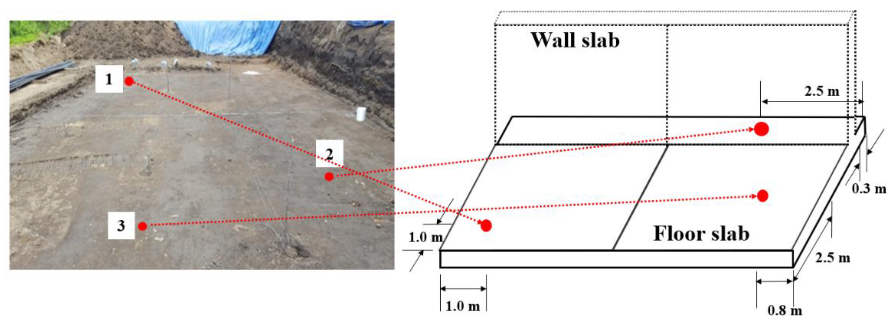
The thermal conductivities of surrounding media were measured by field and laboratory tests. The specifications of measuring equipment are summarized in Table 2. First, KD2-pro complying with the transient hot probe method was adopted to measure the thermal conductivity of ground formations [17] in the field. The thermal conductivity of ground formations was measured at three different locations under the energy slabs (refer to Figure 4). As a result, the average thermal conductivity of ground formations was estimated to be 1.232 W/mK. Meanwhile, the thermal conductivity of concrete slabs was measured from laboratory tests with the aid of QTM-500 complying with the transient hot-wire method [18]. In the laboratory tests, two different concrete specimens were prepared to match up strengths with the constructed concrete slabs. The strength of the wall slab was designed to be higher than the floor slab in order to withstand the pressure of backfill soil. The concrete specimens were cured in dry and saturated conditions for four weeks before measuring thermal conductivity, which corresponded to the moisture content expected in the field. Table 3 summarizes the laboratory measurements for the thermal conductivity of concrete specimens. The concrete specimen cured in the saturated condition shows about 8% higher thermal conductivity than the specimen cured in the dry condition. The average thermal conductivity of concrete specimens was estimated to be 2.05 W/mK.
Figure 5 shows the comprehensive construction procedure of energy slabs. Four types of energy slabs were constructed in the test bed (refer to Table 1). First, heat exchange pipes were arranged in the floor and wall slabs as shown in Figure 5a, b. In this step, steel reinforcements were additionally installed in the wall slab to stand against the earth pressure exerted by the sand backfill. Then, concrete was cast-in-place in the floor and wall slabs. Before finishing work, a thermal insulation layer (PF board) was installed in the floor-type energy slab (refer to Figure 5g). Finally, in order to induce heat exchange between the wall-type energy slabs and ground formations, the backside space of the wall slab was backfilled with sand, and so resembled the in-situ ground conditions (refer to Figure 5i). Figure 6 shows the views of energy slabs at the end of construction.
3. Field Tests for Energy Slab
3.1. In-Situ Thermal Response Tests (TRTs)
In order to evaluate the heat exchange performance of the energy slabs, in-situ TRTs were conducted. Figure 7a shows a schematic description of the TRTs. In the TRTs, temperatures of the inlet and outlet fluid were continuously monitored while applying constant heat injection. Then, the effective thermal conductivity of the ground could be estimated by analyzing the in-situ TRT data complying with the infinite line source model [19,20,21]. This value is closely related to the heat exchange performance of installed GHEXs. The effective thermal conductivity of the ground can be obtained from Equation (1):
However, the infinite line source model works under several critical assumptions. First, the surrounding media are regarded as homogeneous. Thus, the effective thermal conductivity represents the equivalent thermal conductivity of overall media, such as ground formations, concrete and GHEXs. Second, the heat source is assumed as an infinite line-shaped heat source. However, the energy slabs exhibit a horizontally layered configuration, in which the heat source is far from thread-shaped. Therefore, a new terminology of relative heat exchange efficiency per unit pipe length (effpipe) is introduced to indirectly compare the heat exchange performance of constructed energy slabs [2,22]. This term can be used to evaluate the heat exchange performance of various types of energy slabs. The relative heat exchange efficiency per unit pipe length is calculated by Equation (2):
where the slope is the linearized relation between average temperature of inlet and outlet, and the natural logarithm of elapsed time.
The relative heat exchange efficiency per unit pipe length of energy slabs was compared with consideration to the pipe materials. As the TRTs continuously inject high heating power, and the absence of resting period during the test, the influence of ambient air temperature is not significant. Consequently, the wall-type and floor-type energy slabs were compared for the relative heat exchange efficiency per unit pipe length of the energy slabs regardless of the existence of the thermal insulation layer. In a series of TRTs, the average flow rate of circulating fluid was maintained at 29.8 lpm, and the test duration was set to 2880 min for all the cases.
3.2. In-Situ Thermal Performance Tests (TPTs)
As mentioned in Section 3.1, the TRTs cannot be directly applied to energy slabs with the horizontally layered configuration. Moreover, since the TRT was originally developed to estimate the effective thermal conductivity of the ground, it cannot evaluate the actual thermal performance of GHEXs [23]. The in-situ TPT is proposed to evaluate the actual thermal performance of GHEXs because it is simulated under real operational conditions, such as an intermittent operation (i.e., 8 h operation–16 h pause, 12 h operation–12 h pause) [24,25,26]. In this test, an artificial heating load is applied by maintaining a regular inlet fluid temperature using a constant-temperature water bath. From the TPTs, the heat exchange amount is calculated from Equation (3):
The heat exchange of the energy slabs according to the pipe materials was evaluated. In the TPTs, test results can be fairly affected by ambient air temperature if there is no thermal insulation layer, especially during the resting period. Therefore, the thermal performance of the energy slabs, including a thermal insulation layer, was also evaluated. Figure 7b shows a schematic description of the TPTs. Figure 8 and Table 4 summarize the experimental set-up and monitoring instruments adopted in the test. In addition, the connecting tube between the heat exchange pipe and the constant-temperature bath was thermally insulated to minimize the influence of ambient air.
4. Field Test Results and Discussions
4.1. Relative Heat Exchange Efficiency from TRTs
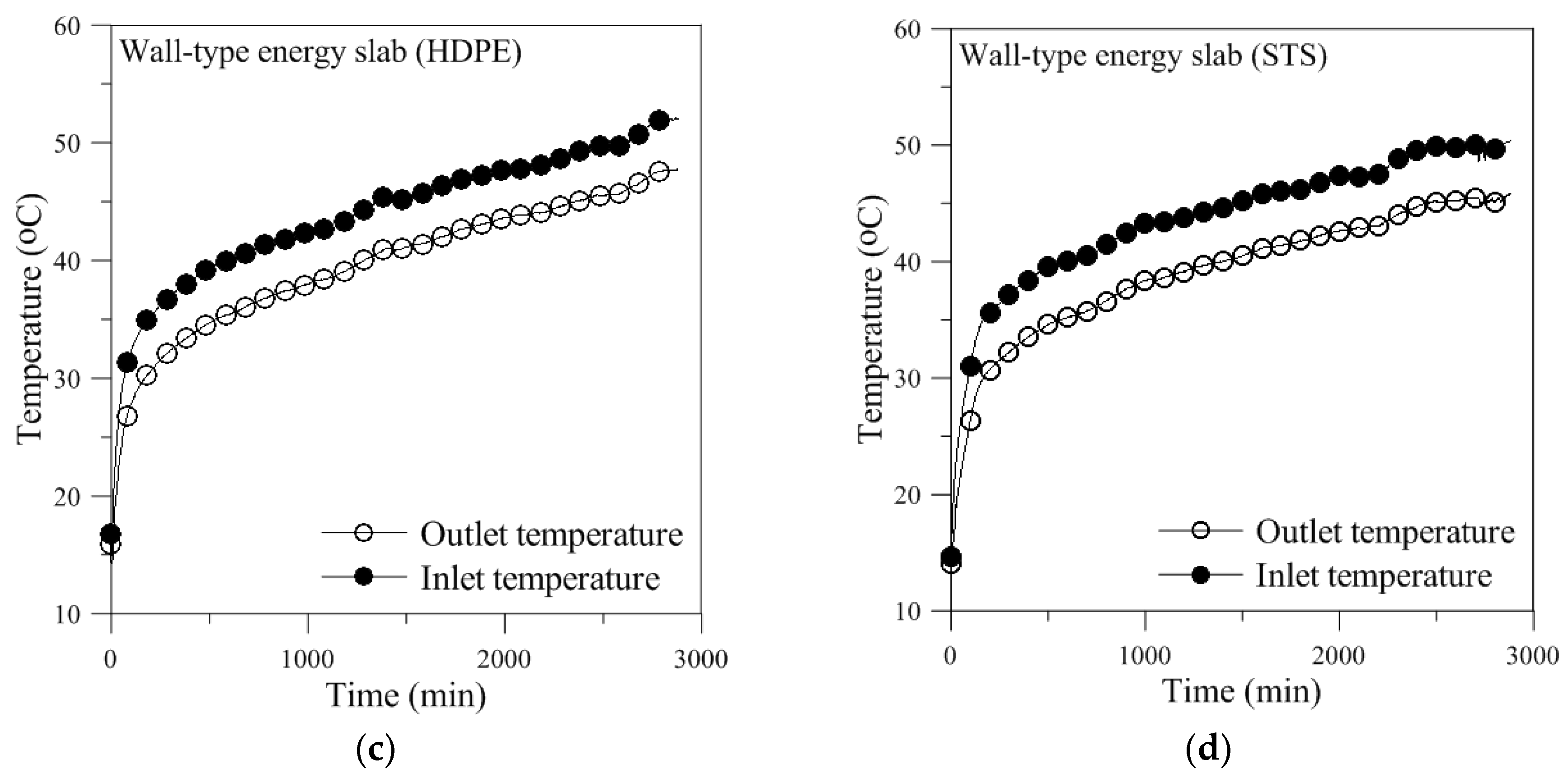
Figure 9 shows temperature changes of the inlet and outlet fluid, and Figure 10 shows the average temperature of the inlet and outlet fluid versus the natural logarithm of time during the TRTs. In addition, Table 5 summarizes the calculated relative heat exchange efficiency per unit pipe length and the total pipe length of each energy slab. In order to compare the relative heat exchange performance of the energy slabs according to the pipe materials, the relative heat exchange efficiency per unit pipe length of the HDPE pipe and the STS pipe was compared for the floor-type and wall-type energy slab, respectively. In the case of the energy slab with the STS pipe, heat exchange performance is estimated to be about 66% higher than the energy slab with the HDPE pipe. This result suggests that if energy slabs are designed with the same pipe length, the STS pipe exhibits a higher heat exchange performance. As mentioned in Section 2.1, this improvement in performance seems attributable to the higher thermal conductivity (k = 16 W/mK) of the STS pipe compared to the thermal conductivity of the HDPE pipe (k = 0.4 W/mK). Therefore, when construction conditions (i.e., the material properties of ground formations and concrete slabs) are predetermined, selecting the heat exchange pipe with the higher thermal conductivity can be an effective way to enhance the thermal performance of energy slabs.
However, the temperature of ground formations and concrete slabs will rise or fall steeply due to excessive heat transfer in the case of a heat exchange pipe with an extremely high thermal conductivity. This phenomenon should lead to deterioration in the long-term thermal performance of energy slabs, which can reduce economic efficiency.
The relative heat exchange efficiency per unit pipe length for the wall-type and floor-type energy slab was similar to each other when the heat exchange pipe was made of the same material (refer to Table 5). This means that there was no difference in the heat exchange performance between the two types of energy slabs in the TRT results. That is, in addition to a floor slab, a side wall slab can be used as a component of energy slabs to maximize the use of geothermal energy that can be generated from the underground space.
4.2. Evaluation of Thermal Performance from TPT
A series of TPTs were conducted for the four types of energy slabs in the heating operation condition. Table 6 summarizes the experimental conditions. The flow rate of a working fluid was determined to make the Reynolds number (Equation (4)) greater than 4000, which can induce turbulence flow inside the pipe. Note that the temperature at the inlet was maintained at 5 °C for the heating mode in the energy slabs.
Figure 11, Figure 12, Figure 13 and Figure 14 show the results of the TPTs. In order to evaluate the effect of a thermal insulation layer, the different types of energy slabs that encases the same pipe materials (i.e., HDPE and STS pipe) were compared to each other.
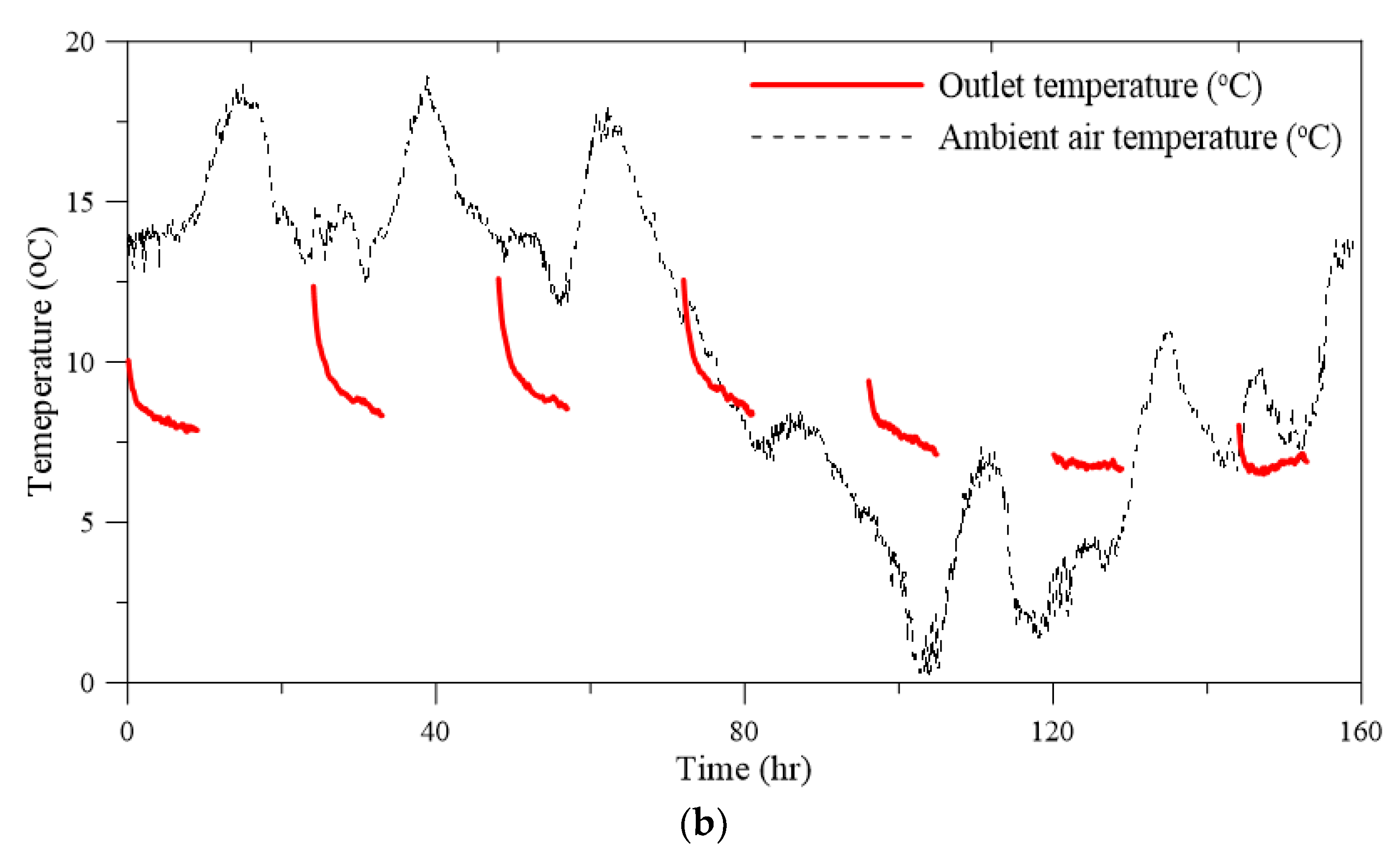
First, in the case of the energy slab with the HDPE pipe, the heat exchange amount was measured at almost zero during the whole test when the energy slab was installed without a thermal insulation layer as shown in Figure 11a. In other words, the heat transfer between the working fluid and the surrounding medium could not occur due to the significant influence of the ambient air temperature. It can be found in Figure 15a that the temperature at B in the concrete slab (refer to Figure 3) showed a similar response to the ambient air temperature. As a result, the outlet fluid temperature monitored during the TPT also varied with the ambient air temperature variation as shown in Figure 11b.
On the contrary, when a thermal insulation layer is installed, a relatively constant temperature was observed at B` in the concrete slab (refer to Figure 3) during the operation of the heat exchanger as shown in Figure 15b. While the temperature measured at A` in the concrete slab showed a similar response to the ambient air temperature (refer to Figure 3 and Figure 15b). Consequently, the existence of a thermal insulation layer induced a measurable heat exchange amount during the entire test as shown in Figure 12.
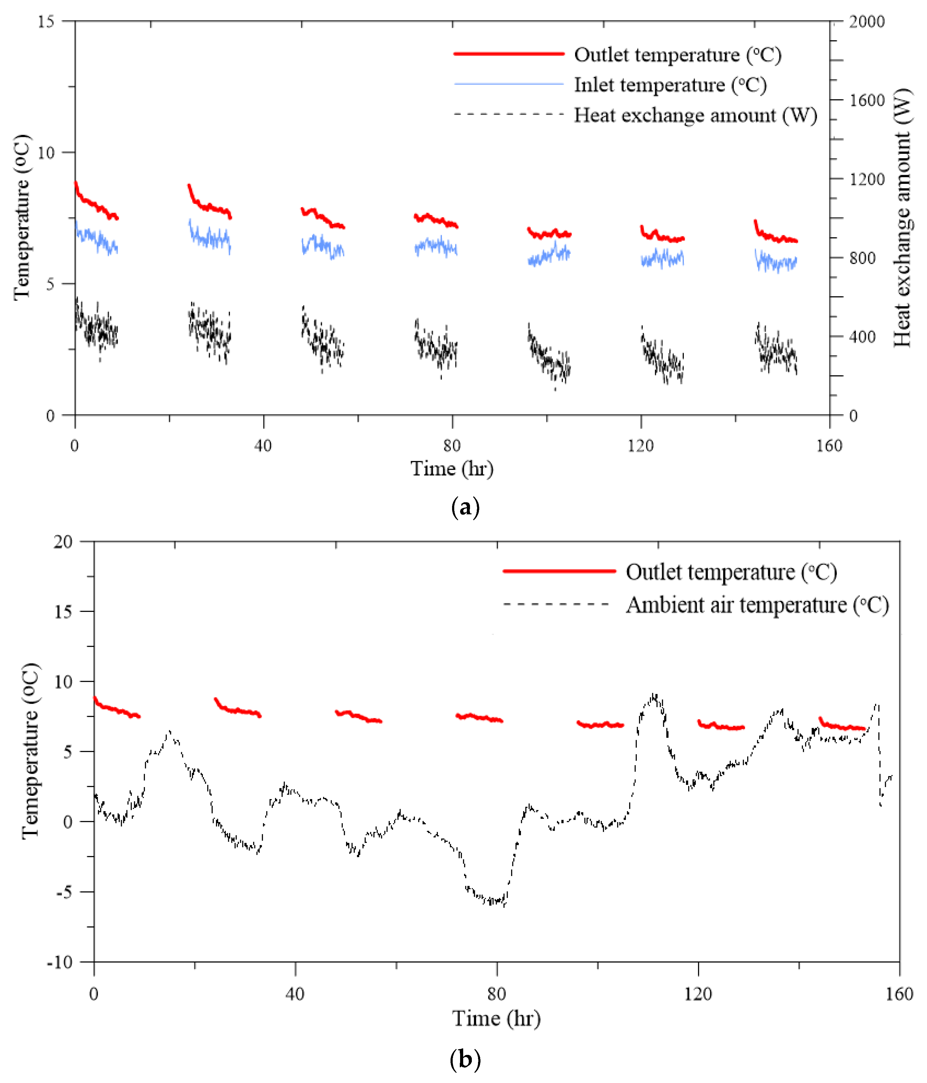
When the STS pipe was installed without a thermal insulation layer in the energy slab, sufficient heat exchange occurred at the early stage of the test, because the air temperature was sufficiently high enough to induce heat exchange at this stage (refer to Figure 13b). However, as the air temperature decreased, a lower heat exchange amount was observed due to the influence of air temperature (refer to Figure 13b). In general, the heat exchange amount of GHEXs reduces as time goes by because the heating (or cooling) load is continuously accumulated in the ground. As shown in Figure 14, this tendency to heat exchange was observed in the energy slabs with a thermal insulation layer, which means that the thermal insulation layer can effectively isolate the energy slab from ambient air temperature during the tests.
The value of the average heat exchange rate per pipe length was calculated to compare the thermal performance of thermally insulated energy slabs according to the pipe materials. In the case of energy slabs with the STS pipe, the value was calculated to be 6.730 W/m, which is improved by about 33.3% compared to the value of energy slabs with the HDPE pipe (5.049 W/m). This result shows a similar trend to the TRT result, which is caused by the difference in the thermal conductivity of pipe materials.
In summary, the installation of thermal insulation layers in energy slabs should be considered in the design stage, and the thermal insulation material should be suitable to minimize the influence of ambient air temperature in the real operation.
The heat exchange amount of energy slabs was evaluated approximately at 400 W per 25 m2 of energy slab unit in this study. As the thermal conductivity of the surrounding medium increases, the thermal performance of GHEX increases [8]. When the energy slab is installed in the actual underground structure, it is expected to show higher thermal performance than the current test bed, in which the thermal conductivity of the ground was measured at 1.232 W/mK on average. Park et al. (2018) showed that the heat exchange amount of the energy pile increased by 10% when the thermal conductivity of the ground increased by 50% [8]. Moreover, when the energy slab is installed in an underground structure far below the frost penetration depth, it is expected that a lower influence of ambient air temperature will enhance the thermal performance of energy slabs. In general, the conventional closed-loop vertical GHEXs have been designed to exchange heat energy of about 3600 W per 50 m of borehole length. According to the TPT results, the energy slab can exchange heat energy of 400 W per 25 m2 of energy slab unit. This means one unit of energy slab with an area of 25 m2 can save about 10% of borehole drilling cost, which is the largest cost portion in construction of closed-loop vertical GHEXs.
5. Conclusions
In this paper, four types of field-scale energy slabs were constructed in a test bed with various configurations. Then, a series of field experiments was conducted to evaluate the thermal performance of energy slabs according to pipe materials and configurations. Some findings are summarized as follows:
- The field experiments indicate that increasing the thermal conductivity of pipe materials can desirably enhance the thermal performance of energy slabs when the other construction conditions are predetermined. However, the extremely high thermal conductivity of the heat exchange pipe could lead to excessive heat transfer through the surrounding media, which may impair the long-term thermal performance of energy slabs.
- There was no difference in heat exchange performance between the wall-type energy slab and the floor-type energy slab. Therefore, the energy slabs can be used in both the wall and floor slab in the underground structures to maximize the use of geothermal energy in a limited underground space.
- It is hard to expect sufficient heat exchange performance in energy slabs installed without a thermal insulation layer, because the temperature in the concrete slab containing heat exchangers is naturally governed by the ambient air temperature if there is no appropriate thermal insulation. This result implies that the installation of a thermal insulation layer in energy slabs is essential, and a thermal insulation material with suitable thermal conductivity to minimize the influence of ambient air should be used.
- The results of the TPTs showed that the average heat exchange amount of the energy slab was estimated to be about 400 W for 25 m2 of the energy slab unit. This value is not comparable to the conventional GHEXs because the field test conditions were not favorable. If energy slabs are installed in an actual underground structure, a larger heat exchange amount would be expected with the aid of the higher thermal conductivity of ground formation and less influence of the ambient air temperature. Additionally, the successful application of energy slabs in large-scale underground structures, such as underground shopping centers and subway stations, would be suitable for replacing the conventional GHEXs.
Author Contributions
Funding acquisition, H.C.; Investigation, S.L.; Methodology, S.P.; Project administration, H.C.; Software, S.P.; Supervision, H.C.; Validation, M.K.; Visualization, M.K.; Writing–original draft, S.L.; Writing–review & editing, H.C.
Acknowledgments
This research was supported by Korea Institute of Energy Technology Evaluation and Planning (KETEP), Ministry of Knowledge Economy (No. 20153030111110) and National Research Foundation of Korea (NRF-2017R1C1B5017580).
Conflicts of Interest
The authors declare no conflict of interest.
Nomenclature
| C | specific heat of circulating fluid (J/kgK) |
| D | Pipe diameter (mm) |
| relative heat exchange efficiency per unit pipe length | |
| L | borehole length (m) |
| Lpipe | total length of heat exchange pipe (m) |
| mass flux of circulating fluid (kg/s) | |
| Q | heat exchange amount (W) |
| amount of heat injection (W) | |
| constant heat injection rate (W) | |
| Re | Reynolds number |
| slope | relationship between average of inlet and outlet temperatures, and natural logarithm of time |
| ΔT | Temperature difference (°C) |
| inlet fluid temperature (°C) | |
| outlet fluid temperature (°C) | |
| Greek Symbols | |
| α | effective thermal diffusivity (m2/s) |
| γ | Euler constant |
| λ | effective thermal conductivity of ground formation (W/mK) |
| μ | Coefficient of viscosity (g/cm s) |
| ρ | Density of working fluid (g/cm3) |
References
- Boënnec, O. Shallow ground energy systems. Proc. Inst. Civ. Eng.-Energy 2008, 161, 57–61. [Google Scholar]
- Lee, C.; Park, S.; Won, J.; Jeoung, J.; Sohn, B.; Choi, H. Evaluation of thermal performance of energy textile installed in Tunnel. Renew. Energy. 2012, 42, 11–22. [Google Scholar] [CrossRef]
- Zhang, G.; Xia, C.; Yang, Y.; Sun, M.; Zou, Y. Experimental study on the thermal performance of tunnel lining ground heat exchangers. Energy Build. 2014, 77, 149–157. [Google Scholar] [CrossRef]
- Zhang, G.; Xia, C.; Sun, M.; Zou, Y.; Xiao, S. A new model and analytical solution for the heat conduction of tunnel lining ground heat exchangers. Cold Reg. Sci. Technol. 2013, 88, 59–66. [Google Scholar] [CrossRef]
- Brandl, H. Energy foundations and other thermo-active ground structures. Geotechnique 2006, 56, 81–122. [Google Scholar] [CrossRef]
- De Moel, M.; Bach, P.M.; Bouazza, A.; Singh, R.M.; Sun, J.O. Technological advances and applications of geothermal energy pile foundations and their feasibility in Australia. Renew. Sustain. Energy Rev. 2010, 14, 2683–2696. [Google Scholar] [CrossRef]
- Morino, K.; Oka, T. Study on heat exchanged in soil by circulating water in a steel pile. Energy Build. 1994, 21, 65–78. [Google Scholar] [CrossRef]
- Park, S.; Lee, S.; Oh, K.; Kim, D.; Choi, H. Engineering chart for thermal performance of cast-in-place energy pile considering thermal resistance. Appl. Therm. Eng. 2018, 130, 899–921. [Google Scholar] [CrossRef]
- Moon, C.E.; Choi, J.M. Heating performance characteristics of the ground source heat pump system with energy-piles and energy-slabs. Energy 2015, 81, 27–32. [Google Scholar] [CrossRef]
- Hwang, K.I.; Woo, S.W.; Kim, J.H.; Shin, S.H.; Kim, Y.S. A study on the seasonal performances evaluation of the horizontal-type geothermal heat exchanger installed in the foundation slabs of complex building. J. Korean Sol. Energy Soc. 2007, 27, 11–17. [Google Scholar]
- Choi, J.-M. Heating and cooling performance of a ground coupled heat pump system with energy-slab. Korean J. Air-Cond. Refrig. Eng. 2012, 24, 196–203. [Google Scholar]
- Choi, J.-M.; Sohn, B.-H. Performance analysis of energy-slab ground-coupled heat exchanger. Korean J. Air-Cond. Refrig. Eng. 2012, 24, 487–496. [Google Scholar]
- Sung, C.; Park, S.; Lee, S.; Oh, K.; Choi, H. Thermo-mechanical behavior of cast-in-place energy piles. Energy. 2018, 161, 920–938. [Google Scholar] [CrossRef]
- Lee, C.; Park, M.; Nguyen, T.B.; Sohn, B.; Choi, J.M.; Choi, H. Performance evaluation of closed-loop vertical ground heat exchangers by conducting in-situ thermal response tests. Renew. Energy 2012, 42, 77–83. [Google Scholar] [CrossRef]
- Kim, D.; Kim, G.; Kim, D.; Baek, H. Experimental and numerical investigation of thermal properties of cement-based grouts used for vertical ground heat exchanger. Renew. Energy 2017, 112, 260–267. [Google Scholar] [CrossRef]
- Yoon, S.; Lee, S.R.; Kim, M.J.; Kim, W.J.; Kim, G.Y.; Kim, K. Evaluation of stainless steel pipe performance as a ground heat exchanger in ground-source heat-pump system. Energy 2016, 113, 328–337. [Google Scholar] [CrossRef]
- ASTM D 5334. Standard Test Method for Determination of Thermal Conductivity of Soil and Soft Rock by Needle Probe Procedure; Annual Book of ASTM Standards. 04.09; ASTM International: West Conshohocken, PA, USA, 1995; pp. 225–229. [Google Scholar]
- ASTM C 1113-90. Test Method for Thermal Conductivity of Refractories by Hot Wire (Platinum Resistance Thermometer Technique); ASTM International: West Conshohocken, PA, USA, 2004. [Google Scholar]
- Carslaw, H.S.; Jaeger, J.C. Conduction of H eat in Solids, 2nd ed.; Oxford Science Publications: Oxford, UK, 1959. [Google Scholar]
- Sharqawy, M.; Mokheimer, E.; Habib, M.; Badr, H.; Said, S.; Al Shayea, N. Energy, exergy and uncertainty analyses of the thermal response test for a ground heat exchanger. Int. J. Energy Res. 2009, 33, 582–592. [Google Scholar] [CrossRef]
- Wagner, R.; Clauser, C. Evaluating thermal response tests using parameter estimation for thermal conductivity and thermal capacity. J. Geophys. Eng. 2005, 2, 349. [Google Scholar] [CrossRef]
- Park, S. Performance of Evaluation and Design method for Cast-In-Place Energy Piles. Ph.D. Thesis, Korea University, Seoul, Korea, 2016. [Google Scholar]
- Zhang, C.; Chen, P.; Liu, Y.; Sun, S.; Peng, D. An improved evaluation method for thermal performance of borehole heat exchanger. Renew. Energy 2015, 77, 142–151. [Google Scholar] [CrossRef]
- Miyara, A.; Tsubaki, K.; Inoue, S.; Yoshida, K. Experimental study of several types of ground heat exchanger using a steel pile foundation. Renew. Energy 2011, 36, 764–771. [Google Scholar] [Green Version]
- Wood, C.J.; Liu, H.; Riffat, S.B. Comparative performance of ‘U-tube’ and ‘coaxial’ loop designs for use with a ground source heat pump. Appl. Therm. Eng. 2012, 37, 190–195. [Google Scholar] [CrossRef]
- Zarrella, A.; De Carli, M.; Galgaro, A. Thermal performance of two types of energy foundation pile: Helical pipe and triple U-tube. Appl. Therm. Eng. 2013, 61, 301–310. [Google Scholar] [CrossRef]
Figure 1.
Configurations of each pipe type. (a) high-density polyethylene (HDPE) pipe; (b) stainless steel (STS) pipe.
Figure 1.
Configurations of each pipe type. (a) high-density polyethylene (HDPE) pipe; (b) stainless steel (STS) pipe.

Figure 2.
Schematic diagram of constructed energy slab.

Figure 3.
Sectional view of energy slab. (a) Wall slab; (b) Floor slab.

Figure 4.
Measurement points for the thermal conductivity of the ground.

Figure 5.
Comprehensive procedure of energy slab construction. (a) Installation of the heat exchange pipe; (b) Steel reinforcement and mold assembly; (c) Cast-in-place of bottom floor slab; (d) Installation of drain board; (e) Cast-in-place of floor slab; (f) Cast-in-place of wall slab; (g) Installation of thermal insulation layer; (h) Finishing work of the energy slab; (i) Sand backfilling.

Figure 6.
Views of constructed energy slab. (a) Side view of energy slab; (b) Front view of energy slab.
Figure 6.
Views of constructed energy slab. (a) Side view of energy slab; (b) Front view of energy slab.


Figure 7.
Schematic of in-situ field tests (thermal response tests (TRT), thermal performance tests (TPT)).
Figure 7.
Schematic of in-situ field tests (thermal response tests (TRT), thermal performance tests (TPT)).

Figure 8.
Experimental set-up and monitoring instruments of thermal performance tests (TPTs). (a) Time controller; (b) Data logger; (c) Flow meter; (d) Constant Temp water bath; (e) Experimental set-up.
Figure 8.
Experimental set-up and monitoring instruments of thermal performance tests (TPTs). (a) Time controller; (b) Data logger; (c) Flow meter; (d) Constant Temp water bath; (e) Experimental set-up.

Figure 9.
Results of in-situ thermal response tests (TRTs) for energy slab (change in inlet and outlet temperature). (a) Floor-type energy slab (high-density polyethylene (HDPE)); (b) Floor-type energy slab (stainless steel (STS)); (c) Wall-type energy slab (HDPE); (d) Wall-type energy slab (STS).
Figure 9.
Results of in-situ thermal response tests (TRTs) for energy slab (change in inlet and outlet temperature). (a) Floor-type energy slab (high-density polyethylene (HDPE)); (b) Floor-type energy slab (stainless steel (STS)); (c) Wall-type energy slab (HDPE); (d) Wall-type energy slab (STS).


Figure 10.
Results of in-situ thermal response tests (TRTs) for energy slab (average temperature changes of inlet and outlet versus natural logarithm of time). (a) Floor-type energy slab (high-density polyethylene (HDPE)); (b) Floor-type energy slab (stainless steel (STS)); (c) Wall-type energy slab (HDPE); (d) Wall-type energy slab (STS).


Figure 11.
Thermal performance test (TPT) results of the wall-type energy slab with the high-density polyethylene (HDPE) pipe (without thermally insulation). (a) Inlet, outlet temperature and heat exchange amount; (b) Outlet and ambient air temperature.
Figure 11.
Thermal performance test (TPT) results of the wall-type energy slab with the high-density polyethylene (HDPE) pipe (without thermally insulation). (a) Inlet, outlet temperature and heat exchange amount; (b) Outlet and ambient air temperature.

Figure 12.
Thermal performance test (TPT) results of the floor-type energy slab with high-density polyethylene (HDPE) pipe (with thermally insulation). (a) Inlet, outlet temperature and heat exchange amount; (b) Outlet and ambient air temperature.
Figure 12.
Thermal performance test (TPT) results of the floor-type energy slab with high-density polyethylene (HDPE) pipe (with thermally insulation). (a) Inlet, outlet temperature and heat exchange amount; (b) Outlet and ambient air temperature.


Figure 13.
Thermal performance test (TPT) results of wall-type energy slab with stainless steel (STS) pipe (without thermally insulation). (a) Inlet, outlet temperature and heat exchange amount; (b) Outlet and ambient air temperature.
Figure 13.
Thermal performance test (TPT) results of wall-type energy slab with stainless steel (STS) pipe (without thermally insulation). (a) Inlet, outlet temperature and heat exchange amount; (b) Outlet and ambient air temperature.


Figure 14.
Thermal performance test (TPT) results of floor-type energy slab with stainless steel (STS) pipe (with thermally insulation). (a) Inlet, outlet temperature and heat exchange amount; (b) Outlet and ambient air temperature.
Figure 14.
Thermal performance test (TPT) results of floor-type energy slab with stainless steel (STS) pipe (with thermally insulation). (a) Inlet, outlet temperature and heat exchange amount; (b) Outlet and ambient air temperature.

Figure 15.
Temperature variation according to depth at center of each high-density polyethylene (HDPE) energy slab (for location of A, B, A` and B` refer to Figure 3). (a) Wall-type energy slab (HDPE, without thermal insulation); (b) Floor-type energy slab (HDPE, with thermal insulation).
Figure 15.
Temperature variation according to depth at center of each high-density polyethylene (HDPE) energy slab (for location of A, B, A` and B` refer to Figure 3). (a) Wall-type energy slab (HDPE, without thermal insulation); (b) Floor-type energy slab (HDPE, with thermal insulation).


Table 1.
Length and thermal conductivity of each heat exchange pipe.
| Type | Material | Thermal Conductivity (W/mK) | Length (m) | Pipe Diameter (mm) |
|---|---|---|---|---|
| Floor-type energy slab | High density polyethylene (HDPE) | 0.4 | 85 | 40 |
| Wall-type energy slab | 58 | |||
| Floor-type energy slab | Stainless steel (STS) | 16 | 53 | |
| Wall-type energy slab | 35 |
Table 2.
Specifications of KD2-Pro and QTM-500.
| Type | KD2-Pro | QTM-500 |
|---|---|---|
| Measuring method | Transient hot probe method | Transient hot wire method |
| Measuring range (Thermal conductivity, W/mK) | 0.02~2 | 0.023~12 |
| Sensing error | ±5%~10% | ±5% |
| Measuring time | 90 sec | 60 sec |
Table 3.
Results of thermal conductivity measurement (concrete sample).
| Concrete Type | Thermal Conductivity (W/mK) | |
|---|---|---|
| Dry Condition | Saturated Condition | |
| Floor slab concrete | 1.992 | 2.257 |
| Wall slab concrete | 1.960 | 2.010 |
Table 4.
Specifications of constant-temperature water bath.
| Type | Specification |
|---|---|
| Bath size (dimension, W × D × H mm) | 350 × 400 × 300 mm |
| Bath capacity | 42 L |
| Power of heater/cooler | 4.0 kW/0.6 kW |
| Range of temperature capacity | −10 °C~98 °C |
| Temperature uniformity | ±1 °C |
| Capacity of circulation pump | 20 L/min |
| Electric requirement | 220 VAC, 60 Hz |
Table 5.
Relative heat exchange efficiency per unit pipe length according to type of energy slab.
| Type | Pipe Material | Pipe Length (m) | effpipe |
|---|---|---|---|
| Floor-type energy slab | HDPE | 85 | 7.57 |
| Wall-type energy slab | 58 | 7.26 | |
| Floor-type energy slab | STS | 53 | 12.61 |
| Wall-type energy slab | 35 | 12.89 |
Table 6.
Test conditions of in-situ thermal performance tests (TPTs).
| Type | Condition |
|---|---|
| Operation type | 8 h operation–16 h pause (intermittent operation) |
| Flow rate | 5 L/min |
| Inlet temperature | 5 °C (heating condition) |
| Sample interval | 5 min |
| Total test duration | 7 days |
© 2018 by the authors. Licensee MDPI, Basel, Switzerland. This article is an open access article distributed under the terms and conditions of the Creative Commons Attribution (CC BY) license (http://creativecommons.org/licenses/by/4.0/).
Share and Cite
MDPI and ACS Style
Lee, S.; Park, S.; Kang, M.; Choi, H. Field Experiments to Evaluate Thermal Performance of Energy Slabs with Different Installation Conditions. Appl. Sci. 2018, 8, 2214. https://doi.org/10.3390/app8112214
AMA Style
Lee S, Park S, Kang M, Choi H. Field Experiments to Evaluate Thermal Performance of Energy Slabs with Different Installation Conditions. Applied Sciences. 2018; 8(11):2214. https://doi.org/10.3390/app8112214
Chicago/Turabian StyleLee, Seokjae, Sangwoo Park, Minkyu Kang, and Hangseok Choi. 2018. "Field Experiments to Evaluate Thermal Performance of Energy Slabs with Different Installation Conditions" Applied Sciences 8, no. 11: 2214. https://doi.org/10.3390/app8112214
Note that from the first issue of 2016, this journal uses article numbers instead of page numbers. See further details here.