High-Speed Welding of Stainless Steel with Additional Compensatory Gas Jet Blow Molten Pool


1
School of Mechanical and Automotive Engineering, South China University of Technology, Guangzhou 510641, China
2
College of Sciences, Guizhou Minzu University, Guiyang 550025, China
*
Author to whom correspondence should be addressed.
Appl. Sci. 2018, 8(11), 2170; https://doi.org/10.3390/app8112170
Submission received: 26 September 2018
/
Revised: 31 October 2018
/
Accepted: 2 November 2018
/
Published: 6 November 2018
(This article belongs to the Special Issue Welding of Steels)
Abstract
:To avoid humping bead defects in high-speed welding, this paper proposes the method of an additional and compensatory gas jet blow molten pool. A pulsed metal inert gas high-speed welding test platform was constructed for compensatory gas jet blow molten pool. A total of 304 stainless steel sheets were used as the welding workpieces under equal heat inputs. Two high-speed butt welding processes were conducted and compared, in which the workpieces were welded with and without compensatory gas jets at 154 cm/min and 167 cm/min, respectively. After high-speed welding with compensatory gas jet blow, the weld appearance was straight, uniform, and high-quality, with no humping bead or undercut defects. The macroscopic morphologies and microstructures of cross-sections of the weld at the toe, near the surface, the middle, and the bottom portion all showed the stirring effect of the gas jet on the molten pool and improved grain refinement degrees. Hardness was enhanced in the weld center and the heat-affected zone. At welding speeds of 154 cm/min and 167 cm/min, the fracture load capacities of the welds were increased by 24.9 and 10.4%, respectively.
1. Introduction
Protective gas is an arc medium acting as ionization, power conversion and stabilizing arc in metal inert-gas welding (MIG). On the one hand, the shielding gas is isolated from the air to protect the welding zone form erosion; on the other hand, the shielding gas produces metallurgical action to improve joint performance. Compared with low-speed MIG, weld beads frequently occur in high-speed MIG, with weld defects such as hump weld bead, under cut, blowhole and surface oxidation [1,2,3,4,5,6,7]. At present, scholars worldwide have seldom studied weld forming after manual intervention [8,9,10,11,12,13,14]. Lu et al. [15] modified the traditional tungsten inert gas (TIG) welding gun to use a double-layer gas channel wherein the inner layer passed through the inert gas protection electrode and the outer layer passed through a mixed gas. They also transmitted active components to the molten pool. This changed the heat convection mode of the molten pool and increased the molten pool depth. Li et al. [16] studied the processing of thin armored steel by using two-layer gas flow TIG welding. The results of metallographic analysis and mechanical property testing showed that welding efficiency was greatly improved by using two-layer gas flow TIG welding technology. Compared to the traditional welding method, double-layer gas flow in TIG welding is a method of manual intervention in weld forming after welding; it can alter the heat convection mode in the molten pool, increase the molten pool depth, and improve welding efficiency. However, because of the limited improvements achieved, the method is not widely used. Zhang et al. [17] used different gas flow process parameters for the molten pool in CO2 laser welding of stainless-steel sheets. They found that, for the top and side flow confluence angle of approximately 40°, the maximum melting width of the weld back could be obtained. They also found that the gas flow nozzle height and flow speed significantly affected weld forming. Pei et al. [18] studied the influence of the shielding gas on the humping tendency of the weld bead during fiber laser welding of thin stainless steel plates, and determined that different gas flow directions affected hump formation on the weld. The study showed that the shielding gas flow suppressed hump formation. Zhou et al. [19] studied the influence of side-blowing gas on the weld structure and corrosion resistance of fiber laser-welded austenitic stainless steel. They established a fluid model and analyzed the influence of different side-blowing gases and flow rates on the temperature and velocity vector fields of the metal steam. These studies introduced different methods with gas flow on the laser welding molten pool and demonstrated experimental effects on weld formation; however, further theoretical analyses and mechanical property testing have not been performed. Oliveira et al. [20,21] studied the complex microstructure dissimilar joints and found that they are explained by the characteristics of laser welding, namely material and heat flow, high cooling rates and thermal gradients within the fusion zone. Cycling tensile testing revealed that joints preserved their superelastic behaviour despite the unfavorable microstructure of the fusion zone which translates into an irrecoverable strain of 2% when cycled at 5% strain. Da et al. [22] introduced a method of introducing ultrasonic energy into arc welding, which is a potential alternative to the traditional mechanical transducer. The arc not only acts as a heat source, but also acts as an ultrasonic emitter and directly acts on the molten pool. Gery et al. [23] predicted the transient temperature distributions and temperature variations of welded plates during welding. Armentani et al. [24] analyzed temperature distribution in butt weld joints, and successive thermo-mechanical analyses were performed to evaluate resulting residual stresses. Hazvinloo et al. [25] analyzed the effects of various flux-cored arc welding (FCAW) parameters on weld width and tensile properties of weld metal extracted from butt joints. Armentani et al. [26] used a parametric model and the elements birth and death in single-pass butt welded joints to simulate the weld filler variation with time. Somashekara et al. [27] studied the effect of area-filling paths on residual stresses developed during twin-wire arc weld-deposition. Cai et al. [28] investigated a three-component shielding gas mixture used in tandem with narrow gap pulsed gas metal arc welding (GMAW), and the effect of its composition on arc behaviors and weld formation. Dong et al. [29,30] studied the pulsed metal inert gas (MIG) high-speed welding of stainless steel and proposed a new method using a compensatory gas jet impinging on the molten pool. They showed that this method could significantly inhibit the formation of humping bead and undercut defects during high-speed welding and increase the welding speed of single wires by nearly three times under equivalent heat input conditions. Moreover, the appearance of the weld was significantly improved, and the microstructure and mechanical properties of the weld were obviously better than those obtained by conventional welding. This paper studies the formation mechanism of hump weld bead and undercut, and puts forward “welding pool compensation gas jet method” based on the idea of human intervention in the movement of welding pool, and uses this new method to study the effects of gas jet on controlling the formation of welding pool, stirring the pool, isolating air protection, and accelerating cooling.
2. Principles and Methods
2.1. Analysis of Humping Bead Formation Mechanism with Relative Speed
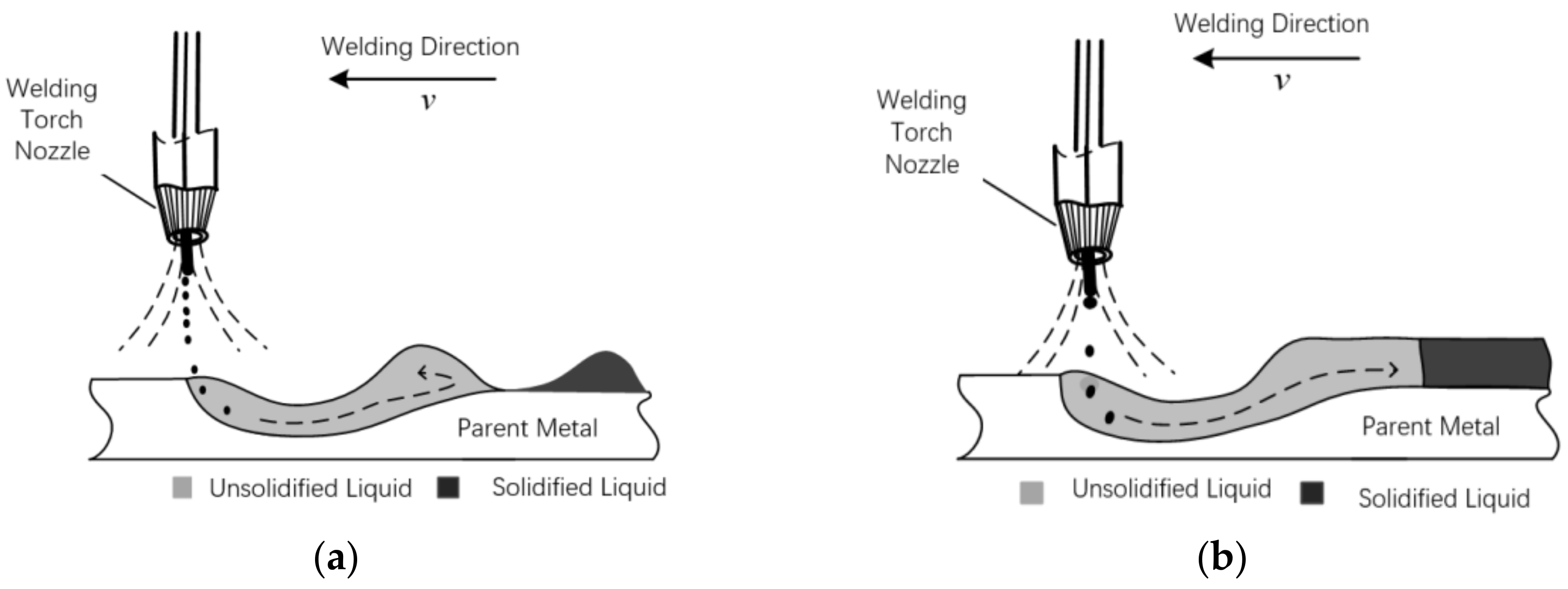
Humping beads appear easily during high-speed welding. The formation mechanism of humping beads is analyzed according to the molten steel flow in the molten pool and the relative speed and angle of the parent material, as shown in Figure 1.
Arc welding is a very complicated process: modeling it accurately is difficult, as is measuring the arc zone data directly. The molten droplet transition and molten pool motion are commonly explained by principles. In the molten pool during conventional welding, the combined effects of arc force, gas flow impact force, molten droplet impact force, and pressure on the molten pool wall surface cause the velocity of the molten steel flow to exceed that of the parent material. If the molten steel transportation and supply capacities are high, the weld is even. During high-speed welding, the actual time of arc force and air impact force acting on the weld pool are decreased, and the positive momentum in the direction of the molten drop and welding increases. The entry of molten drops into the molten pool is a completely inelastic collision process in which momentum is conserved. These factors together cause the relative speed of the molten steel in the molten pool and the parent material to decrease, sometimes approaching zero. As the surface tension of the molten steel is predominant in determining the geometry of the molten pool, periodic accumulations are easily produced; these become humping bead defects.
In this study, a gas jet is introduced to have a vertical impact on the unsolidified steel hump in a method called the compensatory gas jet impinging on the molten pool. The main functions of the method are as follows:
- (1)
- The introduction of the additional gas jet at the rear position near the arc welding zone can affect the high temperature molten pool that has not yet solidified;
- (2)
- The impact force generated by the compensatory gas jet can significantly change the natural solidification mode of the welding molten pool, thereby apparently improving the weld formation and stirring the molten pool;
- (3)
- The gas cover formed during the process of compensatory gas jet impact on the molten pool can effectively extend the protection time on the surface of the molten pool;
- (4)
- The impact force effect formed by the compensatory gas jet and the thermal directional feedback effect caused by the gas cover can increase the molten pool width and weld depth.
2.2. Mechanism Analysis of High-Speed Welding Molten Pool Blowed by Additional and Compensatory Gas Jet
In adopting the compensatory gas jet impinging method, the welding object may be deformed under the gas jet impinging force. The high temperature stainless steel liquid in the molten pool solidifies, thus forming the weld in a very short (millisecond-length) and complex process, and the steel experiences the three stages of liquid, mushy, and solid within this period. To facilitate analysis, the molten pool is completely liquid when it is blown by the compensatory gas jet. Thus, the pool may deform under small external forces. If the internal motion of the liquid in the molten pool is ignored and the liquid is regarded as a whole, the stainless steel liquid before impinging by gas is regarded as a static fluid, and the liquid surface formed is a free liquid surface. When the additional gas jet blows on the surface of the molten pool, this additional force breaks the force balance of the original stainless steel liquid, thus causing the corresponding geometric deformation of the original free liquid surface of the liquid.
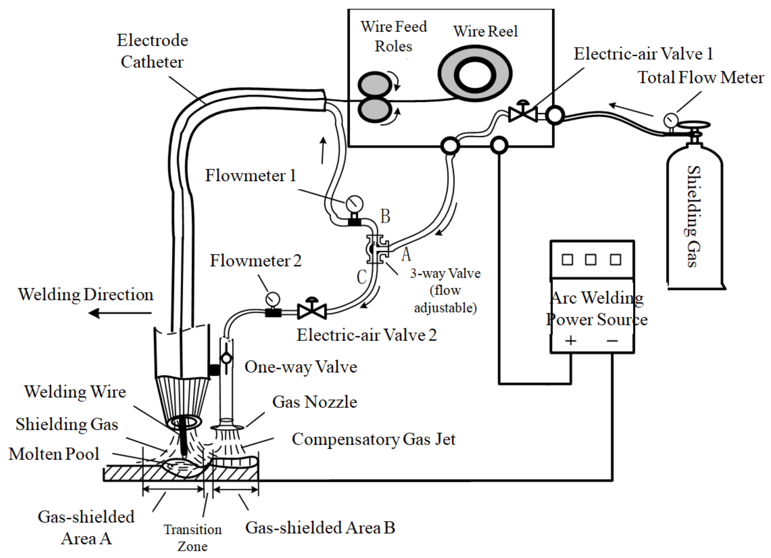
The working principle of the compensatory gas jet impinging on the molten pool is shown in Figure 2. The shielding gas cylinder provides the gas source, the arc welding power source outputs thermal energy, and the automatic wire feeder machine continuously supplies welding wire. The transformation scheme of the devices mainly focuses on the path of the shielding gas, and the specific transformation is implemented as shown in Figure 2.
3. Experimental Materials and Equipment
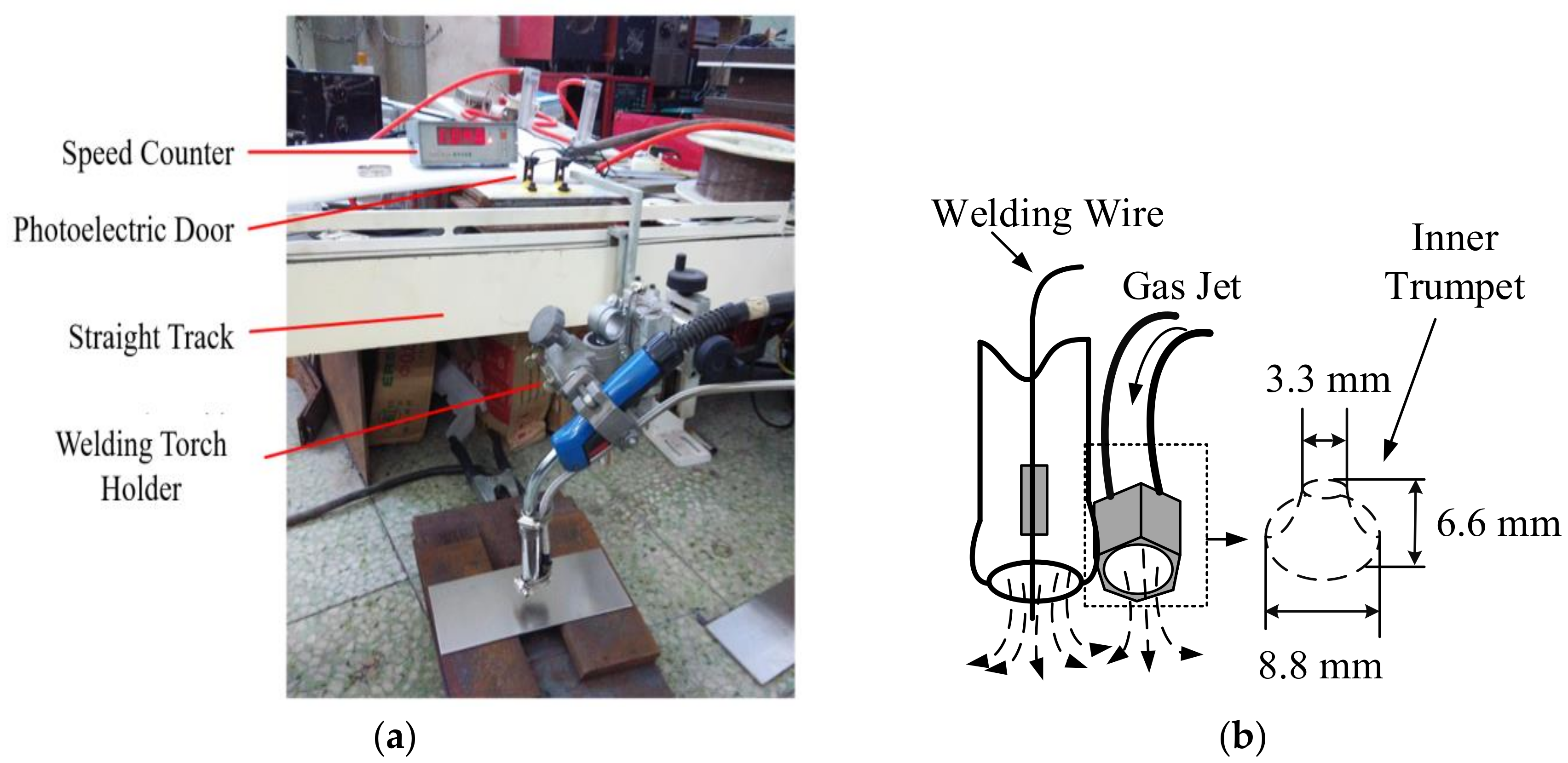
The test platform includes the digital arc welding power source, wire feeder, industrial personal computer, wavelet analyzer, velocity measurement system, and the self-modified compensatory gas jet control system. As shown in Figure 3, the outer part of the compensatory shielding gas nozzle is horn-shaped, aiding in preventing the flow of air towards the impact area. The welding technology test platform uses the intelligent digital signal processing (DSP) arc welding power source as the core. This is a fully functional and relatively complex system that can realize the real-time adjustment and optimization of multiple welding parameters and peripheral welding equipment [31].
Applied to a traditional gas-protected welding system, the method of molten pool blown by a compensatory gas jet should solve the problem of establishing and controlling the new gas flow branches without affecting the adjustment and control of the main gas flow path. The compensatory gas jet system comprises a gas source, pressure-reducing valve, gas flow divider, flow control valve, and compensatory gas jet nozzle. The maximum output current of the arc welding power source is 500 A, which is in line with the high heat input conditions used for high-speed welding.
In the experiment, the angle of base metal for impact of jet flow is 90 degrees while the distance between nozzle and base metal is 8 mm. The gas jet will form vertical impact for formation of liquid metal, which changes the balance of molten pool and causes geometric deformation. After complete solidification, the appearance of the weld joint is better than that of a weld joint without the impact of a gas jet. The hump is formed due to excessive localized accumulation of metal and it is a relatively common weld defect. The compensating gas jet will have an impact on the molten pool of liquid which flows out of the electric arc area of the molten pool. It has the effect of driving metal in the hump location downwards, thus avoiding formation of a hump.
A total of 304 stainless steel sheets were used as the welding workpieces. The welding wire was 308 stainless steel solid-core wire with diameter Φ = 1.6 mm. The chemical composition is shown in Table 1. The thickness of the experimental parent materials was 2.5 mm. Both the main path gas and the compensation gas were argon. The main path gas flow was 20 L/min and the compensation gas jet flow was 15 L/min. Butt welding was performed at speeds of 154 cm/min and 167 cm/min, with peak current Ip = 390 A, base current Ib = 118 A, average current Iv = 268 A, average voltage U = 32 V, and pulse frequency f = 77 Hz. For the convenience of comparison, the heat input line energy of the arc welding power source under the two welding speeds was held constant. Table 2 shows the main welding parameters. In Table 2, sample 1#S and sample 1#B were obtained at the first half and the latter part of the same weld, respectively, as were sample 2#S and sample 2#B.
4. Results and Discussion
4.1. Butt Welding Using Compensatory Gas Jet Impinging on Molten Pool
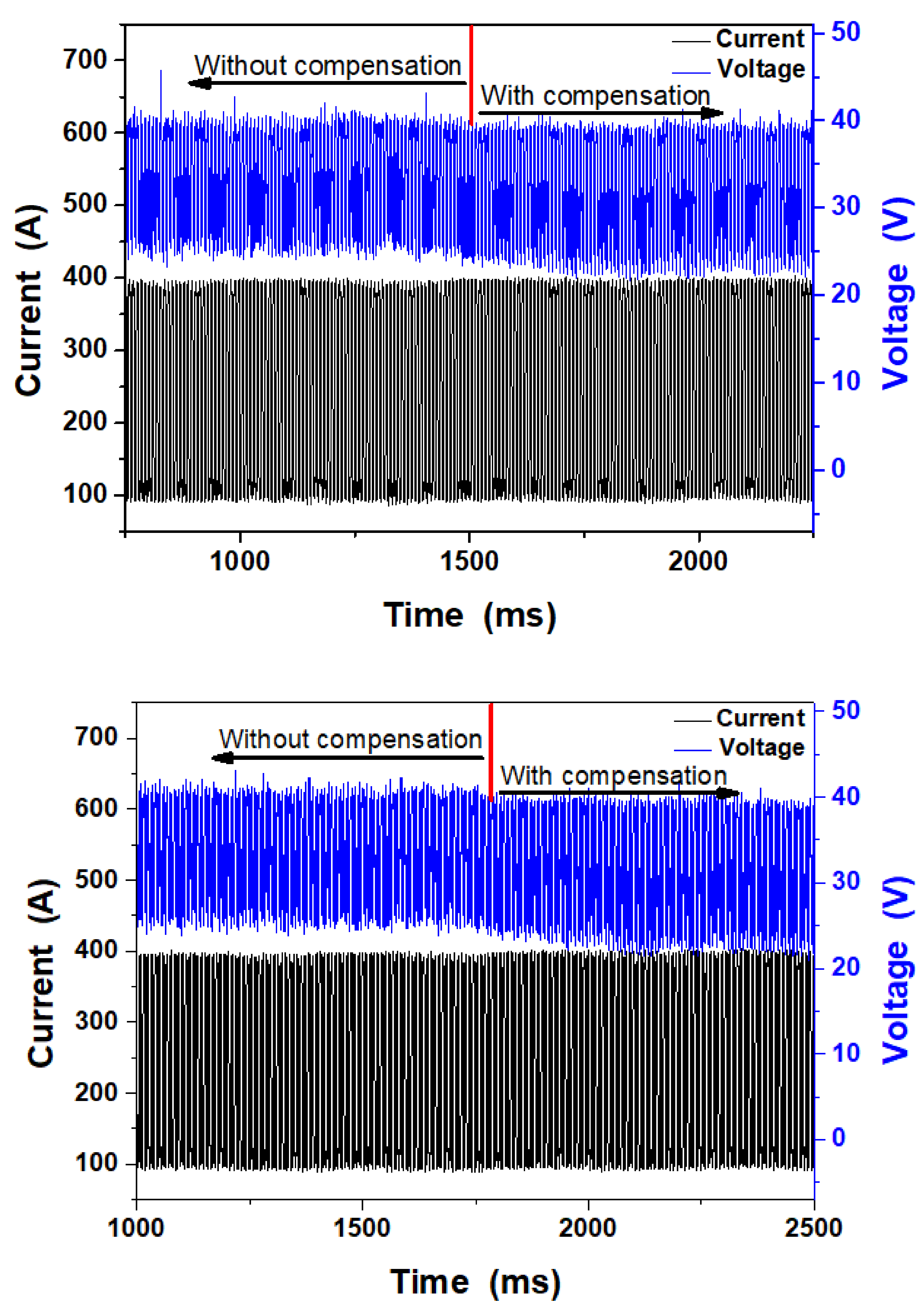
The voltage and current are shown in Figure 4. As shown in Figure 5 and Figure 6, the welding uses a segmental compensatory gas jet and the welding direction proceeds from right to left.
In Figure 4, there is no significant difference in current waveform between sample 1# and sample 2#. However, both sample 1# and sample 2# demonstrate that the average voltage without compensation is obviously higher than with compensation. The results show that the compensation gas jet has a slight disturbance effect on the arc work of the front welding gun when impacting the molten pool, appearing as a slight drop in welding voltage.
Figure 5 shows the front and back of the butt weld. The welding method used is single-sided welding. The back is oxidized since no protective measures are provided, and such oxidation is conducive to judging the difference caused by the two welding methods. The purpose of this experiment is mainly to verify the effect of the compensation gas jet and the conventional welding method on the weld under the same welding parameters, especially the same heat input. As can be seen from Figure 5a, there is a difference in the width of the weld, and the uncompensated weld section is flat, but it is not fully penetrated due to the high excess weld metal. The weld of the compensation gas jet section is better formed than the uncompensated weld section and has been penetrated. The tensile test also shows that the mechanical properties of the compensating gas jet segment are significantly better compared with the uncompensated gas jet segment, showing the prominent role of the method proposed herein.
Figure 6 shows the butt weld formed at a welding speed of 167 cm/min. The uniformity and straightness of the weld in the non-gas jet compensated segment are poor. As metal accumulates locally, humping bead formation is initially high. The humping bead is formed due to the high speed of welding and it is unrelated to the compensating gas jet. The method of impacting the molten pool by a compensating gas jet proposed in the thesis is to exert influence on the molten pool before solidification, so as to ensure the stacking hump of liquid metal flows to a lower position with insufficient liquid metal and to ensure the weld joint is flat, uniform and has a good appearance. However, the shape of the weld with the additional and compensatory gas jet segment is high quality and the molten width is increased. The back view of the weld shows further differences between the two segments. The molten droplet of the compensatory gas jet segment fully penetrates the workpiece, effectively connecting the two parts of the parent material. However, obvious gaps remain in the segment with no compensatory gas jet, and full penetration is not observed.
The above four groups of tests can be divided into two categories, depending on the presence or absence of gas jet compensation. For this group of tests, the other welding parameters can be considered equal, except for the compensatory jet. According to the penetration state, the fusion penetration of the weld is better with the compensatory jet than without it. The welding speeds of 154 cm/min and 167 cm/min both exceed 100 cm/min and are thus considered high-speed welding.
4.2. Analysis of Microstructure
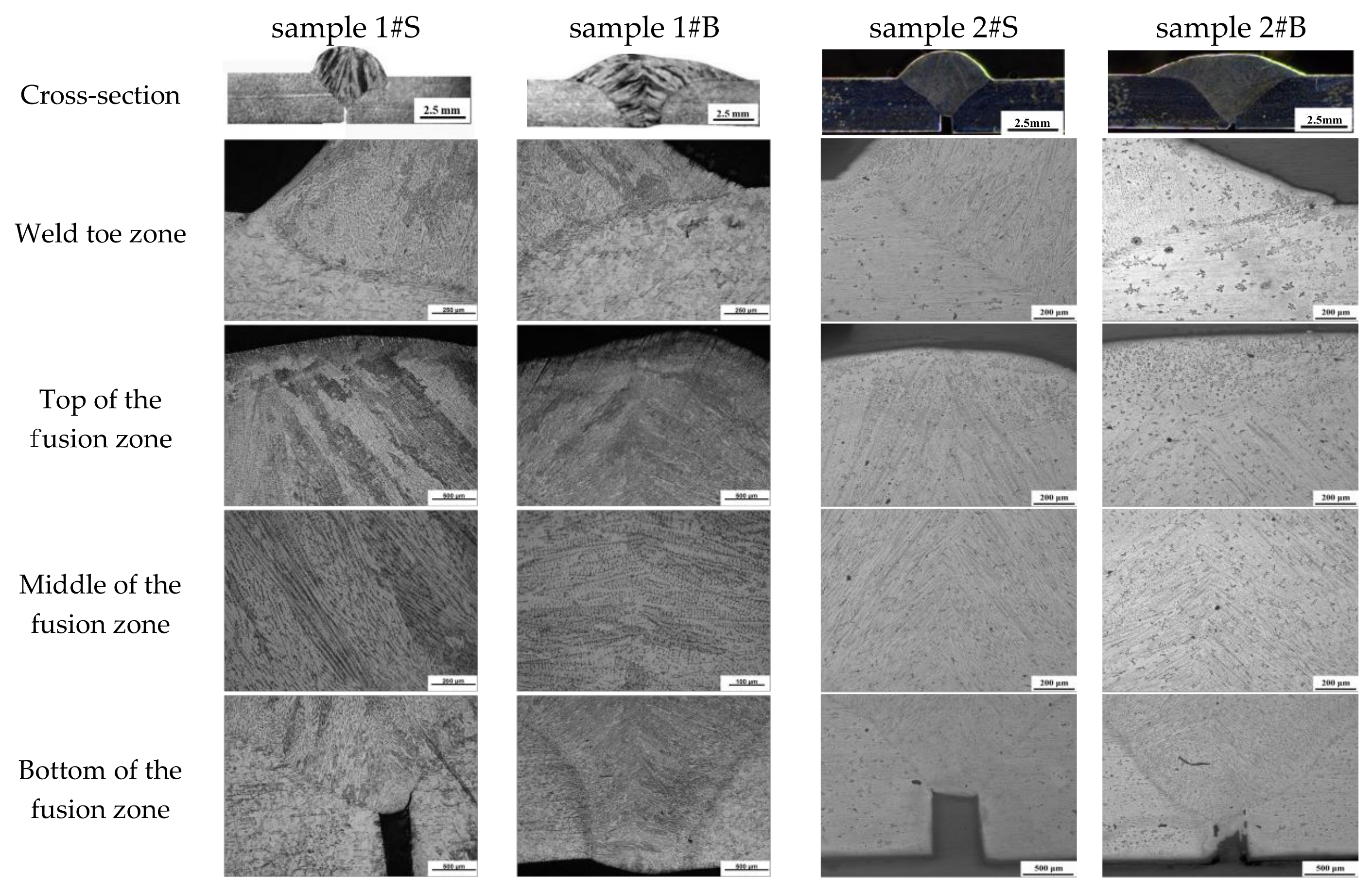
The microstructure of a high speed butt weld is closely related to the mechanical properties of the weld. Segments with and without compensatory jets impinging on the molten pools were selected, cut as samples, and ground. The bright sides of the samples were corroded by concentrated hydrochloric acid (HCl) and concentrated nitric acid (HNO3) at a volume ratio of 3:1. The butt weld of sample 1# and 2# was selected form Figure 5 and Figure 6 for microstructure analysis as shown in Figure 7.
In Figure 7, the molten depth varies significantly in the cross-sections and at the bottom of the fusion zone. With otherwise equivalent parameters, the difference is caused by the presence or absence of the gas jet impinging on the molten pool. The non-blown weld has only approximately 2/3 penetration, while the penetration of the blown weld is improved greatly. The penetration of sample #1 is better than #2 due to more heat input. The fusion line in the weld toe zone is steep in the weld made with no gas jet, and the edge line of the weld above the parent material has a large angle with the parent material. However, in the weld toe zone of the weld made with the gas jet, the welding fusion line is flat, the angle between the weld edge line and the parent material is smaller, and the fusion line is wider compared with the weld toe zone of the weld made with no gas jet. The top of the fusion zone with no gas jet shows thick dendrites with a fan-shaped distribution; a zone of concentrated impurities near the surface is obvious. The microstructure of the fusion zone of sample 1# and 2# is similar. There are almost no defects such as pores and cracks in the fusion zone of both sample 1# and 2#. The top of the fusion zone of the weld made with a gas jet shows a broad area of fine equiaxed grains in the near-surface area. In the lower part of this area, dispersed columnar crystals appear with grains smaller than those seen in top of the fusion zone of the weld made with no gas jet. The middle of the fusion zone without compensation and middle of the fusion zone with compensation show the structures in the middles of the welds. Without compensation, thick dendrites are intermixed with short columnar crystals, while with compensation, relatively fine columnar grains form a staggered distribution. At the bottom of the fusion zone of the weld made with and without compensation show significant differences. The compensatory weld is well fused with the parent material, and crystallization is staggered in the middle. The weld without the compensatory gas jet shows fan–shaped crystallization that grows to the top. These results show that the compensatory argon gas jet can blow on and stir the molten pool, with heat-transfer effects on the molten pool, parent material, and welding zone. This helps the weld to dissipate heat quickly, thus forming fine and uniform grains. However, as the weld without the compensatory argon jet is cooled naturally without external force, thick and directional dendrites grow along a fixed direction.
The protective gas jet impacts the weld metal of the unsolidified molten pool in a vertical direction, so that the hump bead metal periodically accumulated in the original natural form is spread around the periphery under the influence of the jet impact force before solidification. Macroscopically, the jet impact force makes the hump and trough disappear, the melting width significantly increase, the depth of fusion slightly increase, and the excessive weld metal reduce. Microscopically, since the jet stirs the molten pool, the conditions for the formation of coarse dendrites during the cooling process are interrupted, a large number of equiaxed crystals appear, and the crystals are thereby refined. Crystallization in the center of the weld is omnidirectional; the top crystalline impurity layer is thinned, as is the grain, reducing the possibility of cracks on the surface of the weld. The degree of grain refinement is related to the size, impact angle and method used for the compensation gas jet.
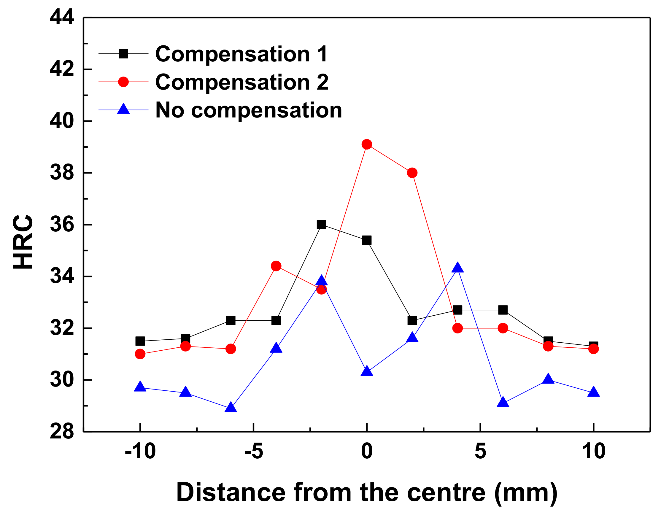
4.3. Rockwell Hardness Test and Analysis
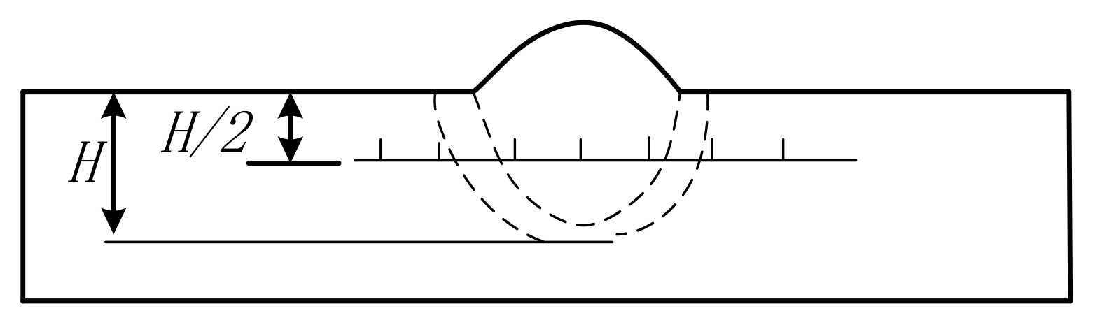
Hardness testing samples were fabricated with reference to the national standard “Welding Joint Hardness Test Method” (GBT2654-2008), with polished weld surfaces. As shown in Figure 8, in the test a spherical indenter was adopted with a 150-kgf (1.47-kN) test force applied for 10 s. The center of the weld was set as the center of the test point and one-half of the molten pool depth was set as the test line of the parallel parent material. A test point was selected every 2 mm (seven total). Test points were located across the weld center, fusion zone, heat-affected area, and parent material. The test was conducted in accordance with the predetermined procedure, including the test point, indentation forming, indentation observation, and measurement. The hardness data is shown in Table 2 and the weld hardness curve comparison chart is shown in Figure 9.
Complex processes such as the melting of the welding wire and parent material, heat cycling in the molten pool, and phase changes in the solidification process during welding, yield different organizational structures and characteristics among the welding metal, fusion zone, heat-affected area, and parent material. Among these differences, the effect of heat cycling causes grain coarsening in the heat-affected zone, thus rendering a heat-affected zone with relatively weak performance. In particular, because austenitic stainless steel has a low thermal conductivity and large linear thermal expansion coefficient, large residual stresses are easily formed in the heat-affected zone as the weld cools.
In the central part, comprising the fusion zone and the heat-affected area, the hardness values of welds #1 and #2 with compensatory gas jets are all higher than those without the compensatory gas jet; the difference is greatest in the central part. This indicates that the compensatory jet impinging on the molten pool has a significant impact on hardness. It is possible that during solidification, blow by the jet stream causes violent movement in the molten pool that refines the grains.
The hardness of the central part, fusion zone and heat-affected area on welds #1 and #2 with compensatory jets is higher than the hardness of without compensatory jets, and the difference of hardness in the central area is the biggest, which clearly shows the effect on hardness that compensatory jet flow shocking the molten pool has. This is because the molten pool is shocked by jet flow during solidification to generate dramatic movement and refine the grain. Hardness in the weld joint area is higher than that in other areas, and the maximum hardness is found near the fusion line at two sides of the weld joints (31-36HRC). The weld made without the compensatory jet firstly forms a crystal nucleus in the fusion zone at the time of crystallization for the molten pool and grows towards the center of the molten pool in the shape of columnar crystal. During this process, the segregation function makes the central part of the weld joints gather more impurities, which makes hardness values in the central area of the weld joint lower than those at both sides (30 HRC). The location with the lowest hardness is near the fusion line of weld joints and parent metal.
The results show two main findings: firstly, that airflow impacts the molten pool to produce a faster cooling rate; and secondly, the gas jet stirs the molten pool to refine the grain in each region. The finer the metal grain, the more grain boundaries there are, and since the grain boundary strength is greater than the intragranular strength, the finer the metal grain is, the greater the strength will be. Moreover, a large number of grain boundaries can also prevent the diffusion of cracks, so the finer the metal grain is, the better the toughness will be.
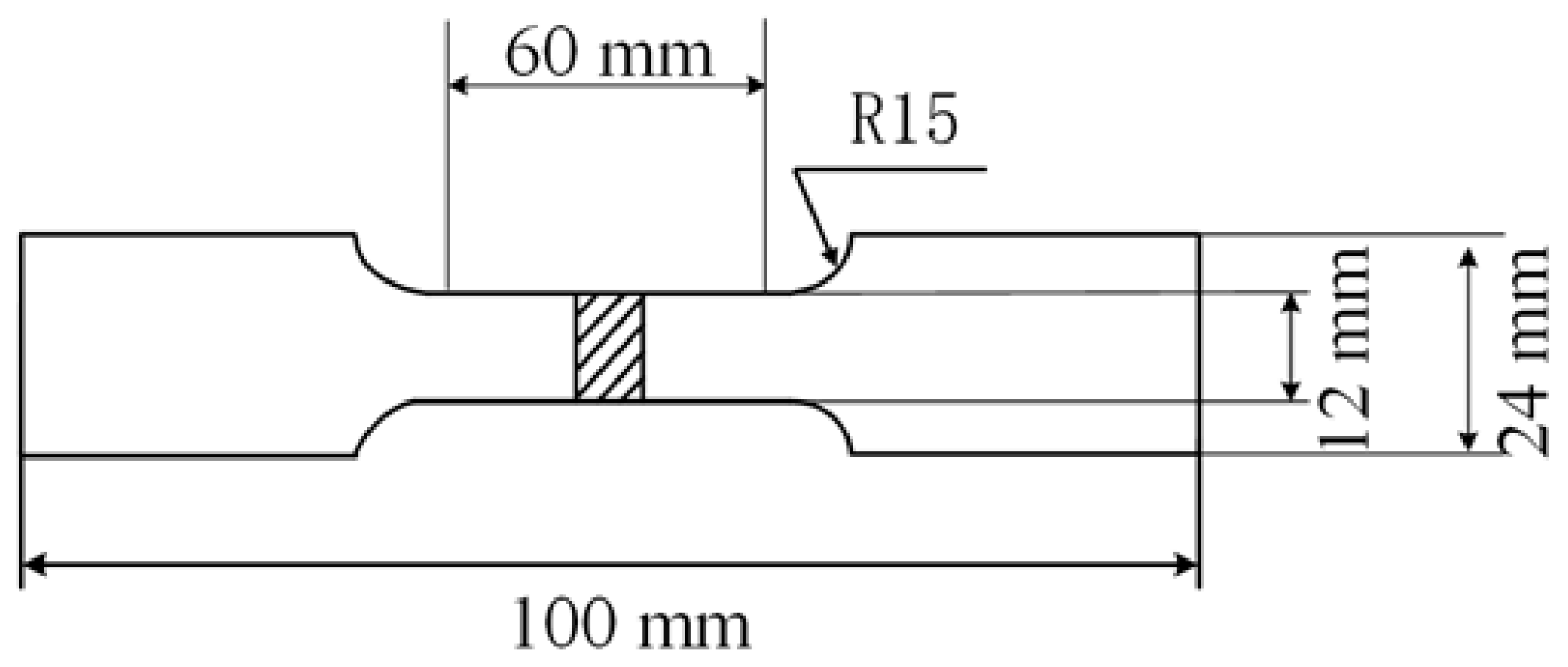
4.4. Tensile Strength Test and Analysis
An INSTRON 8801 hydraulic fatigue testing machine was selected to test the tensile strength of the weld. The device had an axial load capacity of ±100 kN, a maximum load of ±100 kN, a total actuator distance of ±75 mm, and a maximum tensile space of 1480 mm. The test was performed at room temperature. A set of flat-plate surfacing tests and two sets of tensile tests on butt welds were conducted on the selected parent materials with 2 mm thickness. The compensatory gas jet flow rate was set to 15 L/min. Dimensions of the test samples for weld tensile strength are shown in Figure 10.
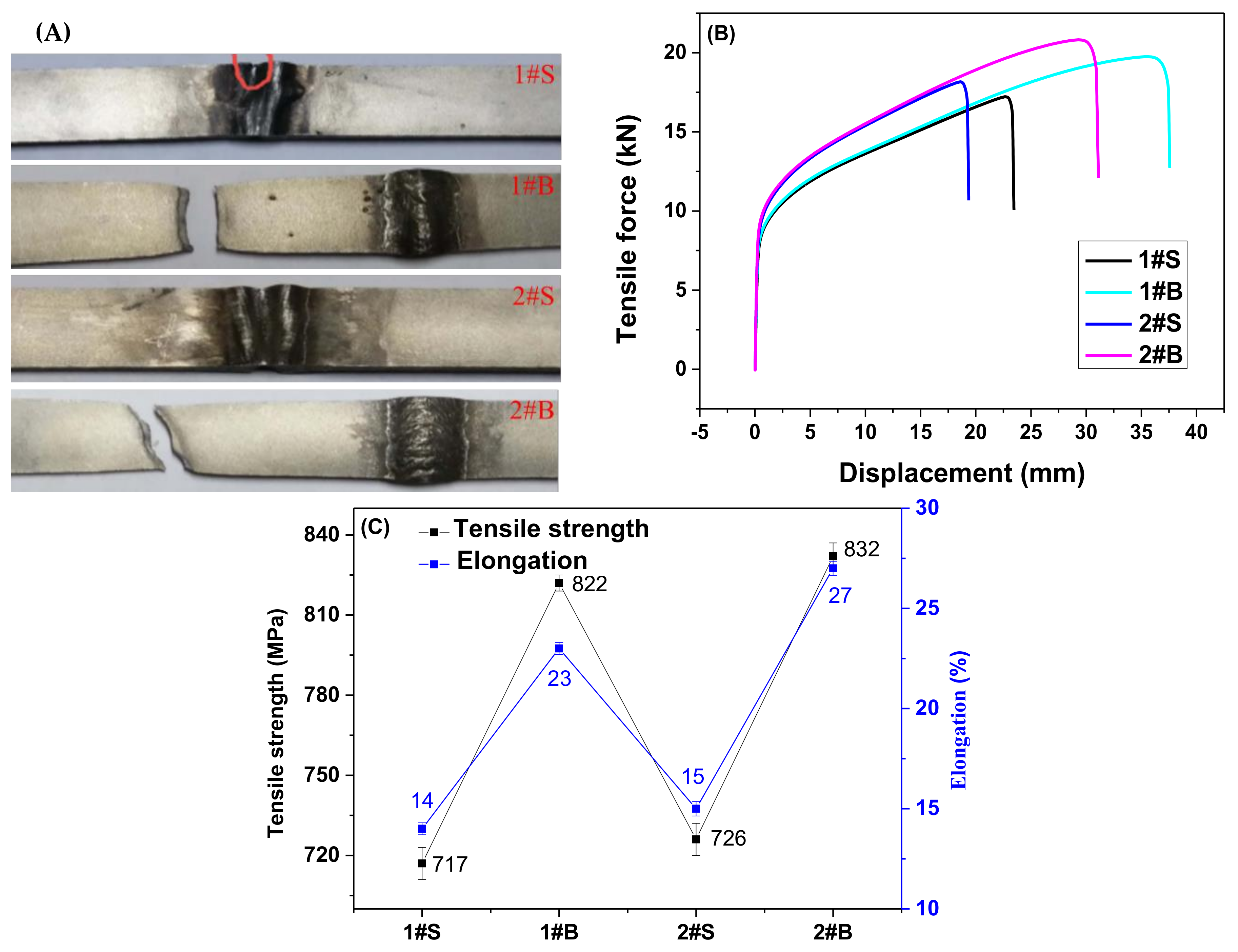
Tensile properties of welded joints are shown in Figure 11. Figure 11A shows the tensile curves of the welded joints. Figure 11B,C show the tensile curves and result of tensile tests, respectively. The test base material is 304 stainless steel plates with the dimensions 200 mm × 50 mm × 3 mm. Each plate’s tensile and yield strength is 838 and 730 MPa, respectively. The tensile strength of sample 1#S, 1#B, 2#S and 2#B is 717 MPa, 822 MPa, 726 MPa and 832 MPa, respectively. The elongation of sample 1#S, 1#B, 2#S and 2#B is 14%, 23%, 15% and 27%, respectively. Therefore, the tensile strength, and elongation of the weld joints with compensation are much higher than those without compensation.
The welds formed with compensatory gas jets are significantly superior to those without compensatory gas jets, in terms of the index parameters such as maximum load, maximum displacement, maximum stress, strain displacement at the yield point, strain displacement at fracture, fracture stress, and fracture load. The fracture position with the compensatory jet flow was located in the parent material, while without compensatory jet flow it was located in the weld. The compensatory jet weld’s fracture occurring far from the heat-affected zone indicates that the heat-affected zone formed in the high-speed welding of 304 stainless steel plates is very small, agreeing with other scholars’ research results. It can be seen from Figure 5 and Figure 6, of the two groups of butt welds, that the weld appearance is intrinsically correlated with the tensile strength. From the front view images, it can be seen that the morphology of the uncompensated segment is uneven, the molten width is low, and the residual height is high. The back view shows that the parent material is not fully penetrated. These apparent differences in appearance are the main reasons for the differences in tensile strength. Butt welds without jet compensation break from the center; this is because the molten droplets fail to fill the gaps and thus the weld becomes the weakest point in the specimen.
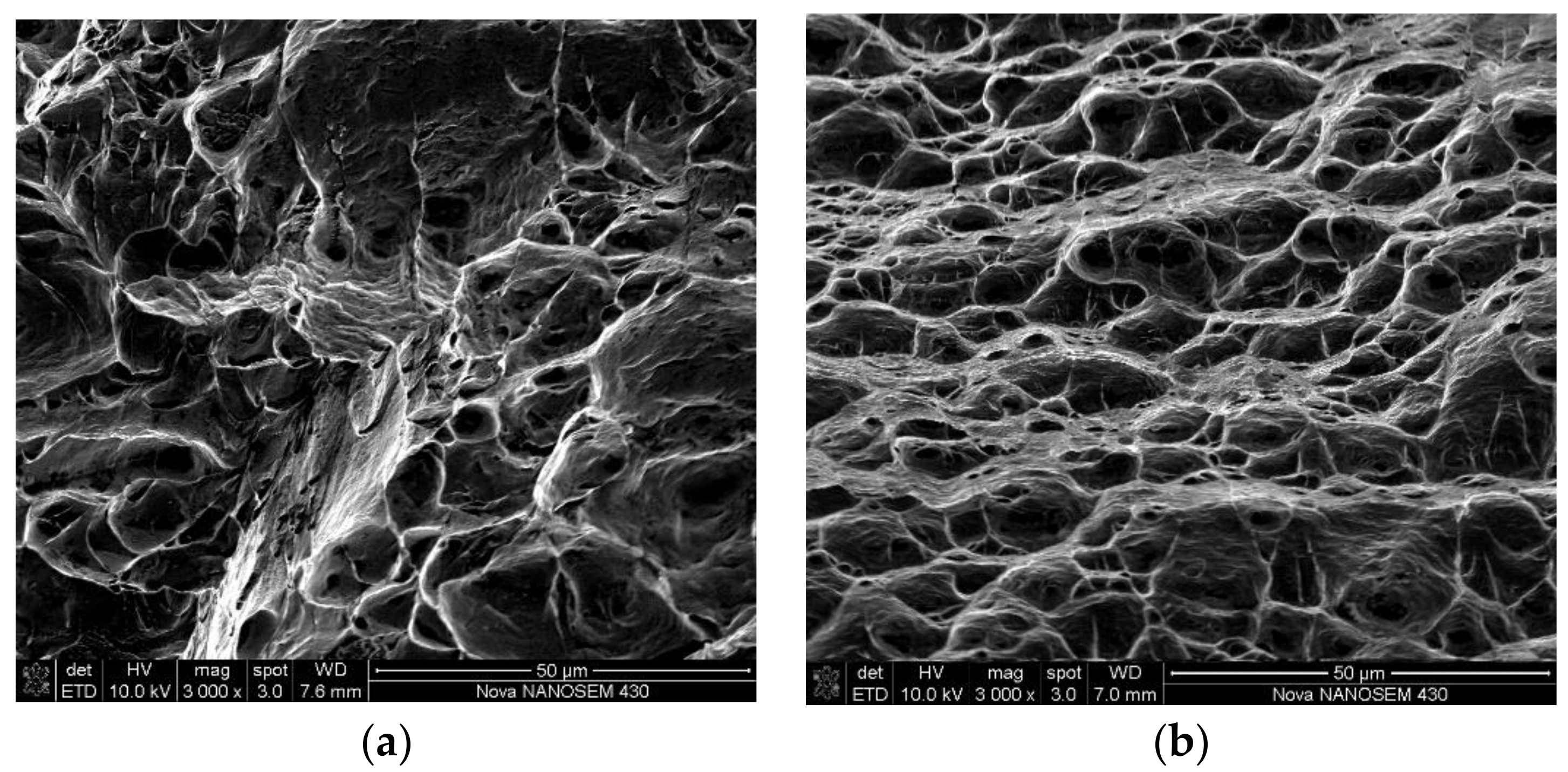
4.5. Fracture Surface Analysis
Fracture cross-sections are shown in Figure 12. The fracture section of the weld joint shows a transgranular fracture along the cleavage plane because of the brittle fracture. The fracture section of the base material shows a large number of irregular dimples and the inclusion of second-phase particles can be observed at the bottom of the dimple, indicating that the joint fracture is ductile.
5. Conclusions
- (1)
- The method of welding with a compensatory gas jet impinging on the molten pool has an obvious positive effect on the solidification of high-speed welds. The appearance of the weld with jet blow is flat, uniform and high-quality, without obvious defects such as humping beads and undercuts.
- (2)
- The effect of impinging and stirring of the molten pool by the compensatory gas jet significantly refines the grains of the weld, accompanying an increase of the molten pool width and a slight increase in molten pool depth. The macroscopic morphology of the weld cross-section, as well as the microstructures in the weld-toe zone, the near-surface region, the middle, and the bottom of the weld all showed the stirring effect of the gas jet on the molten pool, as well as improved grain refinement.
- (3)
- By adopting compensatory gas jet impinging on the molten pool, the hardness values of the weld center and that of the heat-affected zone were enhanced. The capacities of the welds to withstand fractures were increased by 24.9% and 10.4% at the welding speeds of 154 cm/min and 167 cm/min, respectively.
Author Contributions
C.D. and J.X. jointly conceived and designed the experiment. C.D., Z.Z., L.J., and Y.H. jointly performed the experiment and conducted data analysis. C.D. and W.W. analyzed the data and plotted the figures. C.D. and J.X. wrote this paper. Z.Z. and W.W. proofread and translated the paper. J.X. revised the paper, supervised research, and provided financial support.
Funding
This paper was supported by the National Natural Science Foundation project of China (51875213) and the Guizhou Minzu University joint fund project from Guizhou Provincial Department of Science and Technology (Qiankehe LH [2016] 7080).
Conflicts of Interest
The authors declare no conflict of interest.
References
- Meng, X.; Qin, G.; Zou, Z. Investigation of humping defect in high speed gas tungsten arc welding by numerical modelling. Mater. Des. 2016, 94, 69–78. [Google Scholar] [CrossRef]
- Ueyama, T.; Ohnawa, T.; Tanaka, M.; Nakata, K. Effects of torch configuration and welding current on weld bead formation in high speed tandem pulsed gas metal arc welding of steel sheets. Sci. Technol. Weld. Join. 2013, 10, 750–759. [Google Scholar] [CrossRef]
- Wu, C.S.; Hu, Z.H.; Zhong, L.M. Prevention of humping bead associated with high welding speed by double-electrode gas metal arc welding. Int. J. Adv. Manuf. Technol. 2012, 63, 573–581. [Google Scholar] [CrossRef]
- Sundaram, M.; Jose, J.P.; Jaffino, G. Welding defects extraction for radiographic images using C-means segmentation method. In Proceedings of the International Conference on Communication and Networking Technologirs, Sivakasi, India, 18–19 December 2014; pp. 79–83. [Google Scholar]
- Cui, L.; Yang, X.; Wang, D.; Cao, J.; Xu, W. Experimental study of friction taper plug welding for low alloy structure steel: Welding process, defects, microstructures and mechanical properties. Mater. Des. 2014, 62, 271–281. [Google Scholar] [CrossRef]
- Katayama, S.; Kawahito, Y.; Mizutani, M. Elucidation of laser welding phenomena and factors affecting weld penetration and welding defects. Phys. Procedia 2010, 5, 9–17. [Google Scholar] [CrossRef]
- Olsson, R.; Stemvers, M.; Stares, I. High speed welding gives a competitive edge. Weld. Rev. Int. 1995, 14, 129–131. [Google Scholar]
- Alfaro, S.C.A.; Franco, F.D. Exploring Infrared Sensoring for Real Time Welding Defects Monitoring in GTAW. Sensors 2010, 10, 5962–5974. [Google Scholar] [CrossRef] [PubMed] [Green Version]
- Wei, H.L.; Elmer, J.W.; Debroy, T. Crystal growth during keyhole mode laser welding. Acta Mater. 2017, 133, 10–20. [Google Scholar] [CrossRef]
- Li, D.J.; Lu, S.P.; Li, D.Z.; Li, Y.Y. Weld Pool Shape Variations and Electrode Protection in Double Shielded TIG Welding. Adv. Mater. Res. 2010, 97–101, 3978–3981. [Google Scholar] [CrossRef]
- Shanping, L.U.; Dongjie, L.I.; Dianzhong, L.I.; Yiyi, L.I. Double shielded TIG welding method. Trans. China Weld. Inst. 2010, 31, 21–24. [Google Scholar]
- Siewert, E.; Hussary, N.; Schnick, M.; Dreher, M.; Schuster, H.; Wagner, R.; Eichler, S. New GTAW variant for high-throughput aluminum welding. Weld World. 2018, 62, 1–7. [Google Scholar] [CrossRef]
- Howse, D.S.; Lucas, W. Investigation into arc constriction by active fluxes for tungsten inert gas welding. Sci. Technol. Weld. Join. 2000, 5, 189–193. [Google Scholar] [CrossRef]
- Zacharia, T.; David, S.A.; Vitek, J.M.; Debroy, T. Weld pool development during GTA and laser beam welding of Type 304 stainless steel; Part I—Theoretical analysis. Weld. J. 1989, 68, 499–509. [Google Scholar]
- Lu, S.P.; Fujii, H.; Nogi, K. Weld shape variation and electrode protection under Ar-(Ar-O2) double shielded GTA welding. Sci. Technol. Weld. Join. 2009, 14, 726–733. [Google Scholar] [CrossRef]
- Li, G.H.; Yang, Z.K.; Wang, Y.Q. Research on Process of Gdouble Gas Sheielded TIG Welding Applied on Sheet Armour Steel. New Technol. New Process. 2013, 11, 112–115. [Google Scholar]
- Zhang, L.J.; Zhang, J.X.; Gong, S.L. Recent advance in research for keyhole behavior during laser deep penetration welding process. Laser J. 2009, 5, 3–5. [Google Scholar]
- Pei, Y.L.; Shan, J.G.; Ren, J.L. Effect of Welding Speed on Melt Flow Behavior in High Speed Laser Welding Process. Chin. J. Lasers 2013, 5, 61–66. [Google Scholar]
- Zhou, Y.; Cai, Y.; Heng, H.K.; Sheng, J.; Li, F. Influence of side assist gas on microstructure and corrosion resistance of welds of austenitic stainless steel in laser welding. Chin. J. Lasers 2017, 5, 113–120. [Google Scholar]
- Oliveira, J.P.; Miranda, R.M.; Fernandes, F.M.B. Welding and Joining of NiTi Shape Memory Alloys: A Review. Prog. Mater. Sci. 2017, 88, 412–466. [Google Scholar] [CrossRef] [Green Version]
- Oliveira, J.P.; Zeng, Z.; Andrei, C.; Fernandes, F.M.B.; Miranda, R.M.; Ramirez, A.J.; Omori, T.; Zhou, N. Dissimilar laser welding of superelastic NiTi and CuAlMn shape memory alloys. Mater. Des. 2017, 128, 166–175. [Google Scholar] [CrossRef]
- Da, C.T.; Bohórquez, C.E. Ultrasound in arc welding: A review. Ultrasonics 2015, 56, 201–209. [Google Scholar]
- Gery, D.; Long, H.; Maropoulos, P. Effects of welding speed, energy input and heat source distribution on temperature variations in butt joint welding. J. Mater. Process. Technol. 2005, 167, 393–401. [Google Scholar] [CrossRef]
- Armentani, E.; Esposito, R.; Sepe, R. The influence of thermal properties and preheating on residual stresses in welding. Int. J. Comput. Mater. Sci. Surf. Eng. 2007, 1, 146–162. [Google Scholar] [CrossRef]
- Hazvinloo, H.; Honarbakhsh, A. Effect of gas-shielded flux cored arc welding parameters on weld width and tensile properties of weld metal in a low carbon steel. J. Appl. Sci. 2010, 10, 658–663. [Google Scholar]
- Armentani, E.; Pozzi, A.; Sepe, R. Finite-element simulation of temperature fields and residual stresses in butt welded joints and comparison with experimental measurements. In Proceedings of the ASME 2014 12th Biennial Conference on Engineering Systems Design and Analysis, Copenhagen, Denmark, 25–27 June 2014; pp. 25–27. [Google Scholar]
- Somashekara, M.; Naveenkumar, M.; Kumar, A.; Viswanath, C.; Simhambhatla, S. Investigations into effect of weld-deposition pattern on residual stress evolution for metallic additive manufacturing. Int. J. Adv. Manuf. Technol. 2017, 90, 2009–2025. [Google Scholar] [CrossRef]
- Cai, X.; Fan, C.; Lin, S.; Yang, C.; Hu, L.; Ji, X. Effects of shielding gas composition on arc behaviors and weld formation in narrow gap tandem GMAW. Int. J. Adv. Manuf. Technol. 2017, 91, 3449–3456. [Google Scholar] [CrossRef]
- Dong, C.W.; Xue, J.X.; Min, X.; Qiang, Z. Effects of additional compensation shielding gas on high speed pulsed MIG welding seams. Trans. China Weld. Inst. 2015, 36, 85–88. [Google Scholar]
- Dong, C.W.; Xue, J.X.; Jiang, X.M. In Effects of additional compensation shielding gas on stainless steel pulse MIG welding. In Proceedings of the 2016 IEEE Workshop on Advanced Robotics and its Social Impacts (ARSO), Shanghai, China, 8–10 July 2016; pp. 128–133. [Google Scholar]
- Yao, P.; Xue, J.X.; Zhou, K.; Wang, X.; Zhu, Q. Symmetrical transition waveform control on double-wire MIG welding. J. Mater. Process. Technol. 2016, 229, 111–120. [Google Scholar] [CrossRef] [Green Version]
Figure 1.
Schematic of the relative speeds of molten steel flows and parent material: (a) Low relative speed (high-speed welding); (b) high relative speed (normal welding).
Figure 1.
Schematic of the relative speeds of molten steel flows and parent material: (a) Low relative speed (high-speed welding); (b) high relative speed (normal welding).

Figure 2.
Schematic of the molten pool blown with compensatory gas jet during welding.

Figure 3.
Self-made compensatory gas jet test platform: (a) Diagram of the compensatory gas jet system; (b) diagram of compensatory gas jet nozzle structure.
Figure 3.
Self-made compensatory gas jet test platform: (a) Diagram of the compensatory gas jet system; (b) diagram of compensatory gas jet nozzle structure.

Figure 4.
Current and voltage waveforms during the butt welding of 304 stainless steel: (a) Sample 1#; (b) sample 2#.
Figure 4.
Current and voltage waveforms during the butt welding of 304 stainless steel: (a) Sample 1#; (b) sample 2#.

Figure 5.
Weld bead shape of sample 1#: (a) Front view; (b) back view.
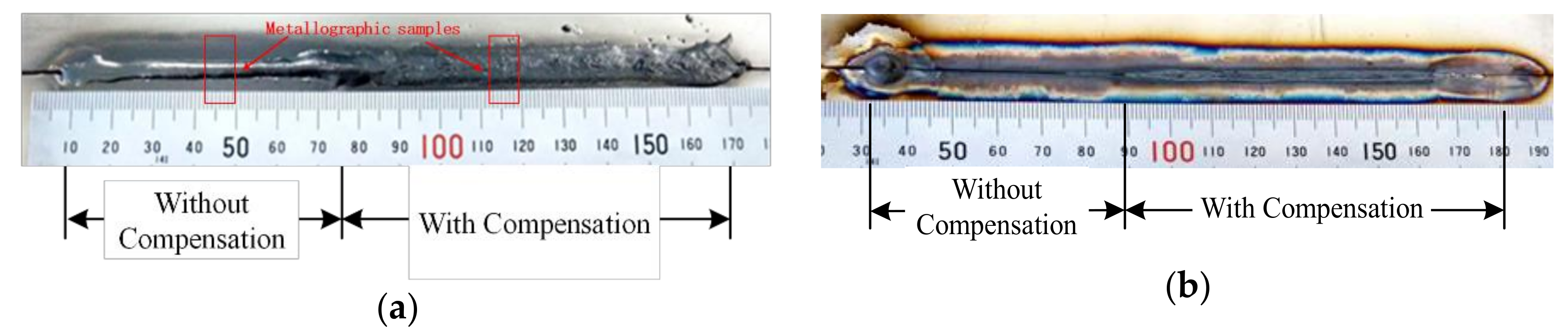
Figure 6.
Weld bead shape of sample 2#: (a) Front view; (b) back view.
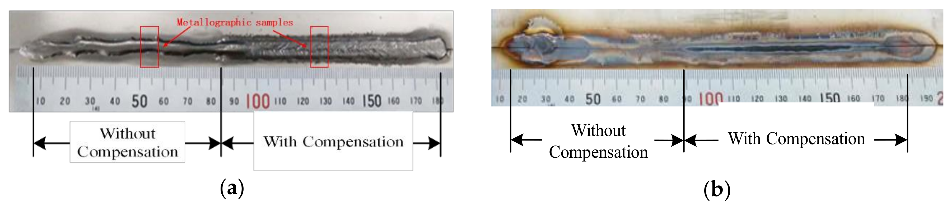
Figure 7.
Microstructures of butt welds formed at high-speed welding.

Figure 8.
Weld hardness test point.

Figure 9.
Comparison of hardness curves of welds formed with and without compensatory gas jets.

Figure 10.
Dimensions of tensile strength test specimens.

Figure 11.
Tensile properties of welded joints: (A) Tensile samples; (B) tensile curves; (C) result of tensile tests.
Figure 11.
Tensile properties of welded joints: (A) Tensile samples; (B) tensile curves; (C) result of tensile tests.

Figure 12.
Photographs of fractured tensile samples: (a) Weld joint, (b) base material.


Table 1.
Chemical composition of ER-308 stainless steel solid welding wire (%).
| Component | C | Mn | Si | Cr | Ni | Mo | P | S | Cu | Ti | Nb |
| Test Value | 0.027 | 1.81 | 0.55 | 19.71 | 9.84 | 0.02 | 0.014 | 0.006 | 0.03 | – | – |
Table 2.
Main welding parameters of high-speed welding of stainless steel.
| Number | Welding Speed v (cm/min) | Compensatory Status | Average Current I (A) |
|---|---|---|---|
| 1#S | 154 | without compensation | 268 |
| 1#B | 154 | with compensation | 268 |
| 2#S | 167 | without compensation | 268 |
| 2#B | 167 | with compensation | 268 |
© 2018 by the authors. Licensee MDPI, Basel, Switzerland. This article is an open access article distributed under the terms and conditions of the Creative Commons Attribution (CC BY) license (http://creativecommons.org/licenses/by/4.0/).
Share and Cite
MDPI and ACS Style
Dong, C.; Xue, J.; Zhang, Z.; Jin, L.; Hu, Y.; Wu, W. High-Speed Welding of Stainless Steel with Additional Compensatory Gas Jet Blow Molten Pool. Appl. Sci. 2018, 8, 2170. https://doi.org/10.3390/app8112170
AMA Style
Dong C, Xue J, Zhang Z, Jin L, Hu Y, Wu W. High-Speed Welding of Stainless Steel with Additional Compensatory Gas Jet Blow Molten Pool. Applied Sciences. 2018; 8(11):2170. https://doi.org/10.3390/app8112170
Chicago/Turabian StyleDong, Changwen, Jiaxiang Xue, Zhanhui Zhang, Li Jin, Yu Hu, and Wei Wu. 2018. "High-Speed Welding of Stainless Steel with Additional Compensatory Gas Jet Blow Molten Pool" Applied Sciences 8, no. 11: 2170. https://doi.org/10.3390/app8112170
Note that from the first issue of 2016, this journal uses article numbers instead of page numbers. See further details here.