Critical Review on the Developments and Future Aspects of Adsorption Heat Pumps for Automobile Air Conditioning


1
Interdisciplinary Graduate School of Engineering Sciences, Kyushu University, Kasuga-koen 6-1, Kasuga-shi, Fukuoka 816-8580, Japan
2
Green Asia Education Center, Interdisciplinary Graduate School of Engineering Sciences, Kyushu University, Kasuga-koen 6-1, Kasuga-shi, Fukuoka 816-8580, Japan
3
Global Technology Division, Calsonic Kansei Corporation, 8 Sakae-cho, Sano-shi, Tochigi 327-0816, Japan
*
Authors to whom correspondence should be addressed.
Appl. Sci. 2018, 8(11), 2061; https://doi.org/10.3390/app8112061
Submission received: 9 October 2018
/
Revised: 22 October 2018
/
Accepted: 23 October 2018
/
Published: 25 October 2018
(This article belongs to the Special Issue Sciences in Heat Pump and Refrigeration)
Abstract
:Featured Application
Adsorption systems for automobile air conditioning.
Abstract
Emission and heat rejection from automobiles are largely responsible for urban environmental issues. Adsorption systems driven by engine waste heat exhibit huge potential to meet the demand for cabin thermal comfort while improving fuel economy. However, the mechanical vapour compression (MVC) systems are still the undisputed champions in automobile air conditioning. This paper provides a critical review on the development and progress of adsorption heat pumps specifically for automobile air conditioning. In doing so, some of the progress and development in land-based adsorption chillers (heat pump), which are not realistically relevant to automobile adsorption systems, are explicitly excluded. Matching the energy density, durability, and reliability of the MVC systems remain major hurdles. The importance of improving the energy density based on the overall system weight or volume, real-world tests under various driving modes and durability aspects are discussed.
1. Introduction
Emission from the vast numbers of vehicles significantly contributes to the adverse urban environmental issues. Subsequently, urban heat island effect and serious air pollution are becoming existential threats to city dwellers. Approximately 55% of the world’s population resides in urban areas while this number is projected to be as high as 68% in 2050 [1]. As the urban population increases, the number of cars running in cities is expected to increase proportionally. This situation might become worse if public transportation is poor or underdeveloped. Meanwhile, total vehicle production increased by 2.4%, while the production for 2017 was 95 million units [2]. According to the 2018 report by the Japan Automobile Manufacturers Association (JAMA), Motor Industry of Japan 2018, the total number of passenger cars produced in 2017 was approximately 8.3 million which is a 5.8% increment [3].
The thermal efficiency of most internal combustion engines is well under 40% while most cars reject approximately 60–65% of the thermal energy from the combustion of fuel via the engine coolant and the exhaust [4]. Japan’s National Greenhouse Gas Emissions reported that ~7% of the CO2 emission in 2016 came from transportation and automobiles [5]. Thus, urban cities are subjected to the thermal energy rejection from vehicles, and the effective recovery of this rejection will immediately reduce the rise in the ambient temperature. Due to the urban heat island effect, the usage of an onboard air conditioner to achieve cabin thermal comfort has increased. However, conventional mechanical vapour compression (MVC) systems consume part of the engine power to operate the compressor and hence worsen fuel economy. Figure 1 depicts the breakdown of energy utilisation by a typical automobile. Approximately 65% of the thermal energy from the combustion of fuel is rejected through the exhaust, the engine coolant and the cabin heating during winter. This energy, for the cabin heating, can be considered as the useful effect in winter while in summer it can be considered as waste heat. Of the remaining 35% of thermal energy, friction losses and electricity generation account for 4% each. On average, the onboard air-conditioner consumes ~5% of the engine torque. Depending on the cabin size, the capacity of the installed air conditioner varies. Following Lambert and Jones, Table 1 lists the influence of operating the air conditioner on the performance of different types of vehicles, i.e., mini, small, and standard as per the classification under the Road Vehicles Act of Japan [3,6]. It is noted that the mechanical air conditioner used up a significant portion of the power production, especially during idling. Hence, the implementation of cabin air-conditioning systems that utilise or recover waste heat from the engine will provide a two-pronged benefit: (i) improved fuel economy and (ii) reduced heat rejection at a lower temperature.
2. Alternate Air Conditioning Technologies Using Engine Waste Heat
The internal combustion engines of automobiles reject a significant amount of energy. The highest recorded thermal efficiency of the engine installed on a passenger vehicle is ~40% while most vehicles perform at approximately 20–30% efficiency [7]. After accounting the drive, friction, and generating for electronic parts, the total available heat loss is ~65%. Hence, the effective recovery of waste heat from the combustion process will improve the overall fuel energy utilisation. The immediate and onboard application of the waste heat recovery is the cabin climate control. Cabin climate control using a mechanical vapour compression (MVC) system consumes a significant amount of energy. It is reported that the automobile air conditioning (A/C) can increase fuel consumption up to 50% [8]. Many researchers have explored a number of heat-activated cooling processes. These include (i) Peltier TE generator, (ii) absorption cycles, and (iii) adsorption cycles. Saidur et al. reviewed developments and technologies for the waste heat recovery of exhaust gas including thermoelectric generators, the organic Rankine cycles, newly-developed turbocharger technology, and a six-stroke cycle engine [9].
In general, the thermal energy recovery from the IC engines of automobiles can be achieved from two sources: (i) waste heat from the engine coolant circuit and (ii) the thermal energy from the exhaust stream. Table 2 summarises the advantages and disadvantages together with the temperature levels of these heat recovery techniques.
3. Working Principles and COP Limit of Adsorption Systems
Adsorption systems employ sorption phenomena between the solid surfaces and gas molecules [12,13,14,15]. Unsaturated solid surfaces can attract gas molecules releasing some energy when these molecules are trapped by van der Waals forces. Being weak binding forces, the molecules can easily be released by supplying energy in the form of a low-temperature heat source. Thus, the desorption process is an endothermic process while the adsorption process is exothermic. When employed in a cycle, these adsorption and desorption processes can be applied to perform heat pumping. Adsorption process utilises the chemical potential stored in the adsorbent and can trigger latent heat removal from the evaporator due to the vapour migration [16]. On the other hand, desorption process releases previously-adsorbed gas molecules to the condenser while restoring the chemical potential. From the thermodynamic point of view, adsorption systems can be considered a thermodynamic cycle that consists of a heat engine and a heat pump. The heat engine cycle operates between the high temperature (heat source for regeneration) and medium temperature (heat sink for condensation) reservoirs. The work produced by this heat engine is employed to pump heat from the evaporator (low-temperature reservoir) to the intermediate temperature reservoir via the adsorption process. Figure 2 shows the Clapeyron diagram of an adsorption heat pump. The cycle consists of two isobars and two isosters [17,18,19]. Adsorption and desorption processes perform under isobaric conditions while the preheating and precooling of the adsorber beds are achieved at constant uptakes. The saturated adsorber bed is preheated at constant uptake, i.e., until it reaches the condenser pressure (1‒2) while the corresponding temperature is T2. The adsorber bed is then regenerated isobarically (2‒3) by supplying thermal energy, i.e., Qd. The dry or unsaturated bed is then cooled down to the evaporator pressure (3‒4). The adsorption process then commences (4‒1) and the cycle completes.
The key parameters often used in judging the efficacy of an adsorption system are the specific cooling capacity (SCP) and the coefficient of performance (COP). Both SCP and COP strongly depend on the heat source temperature. On the other hand, the performance of the adsorption systems depends on the choice of the working pairs. Regardless of the working pairs, the theoretical limit of an adsorption heat pump can be calculated using the Carnot COP. The Carnot COP of an adsorption cycle operating among three temperature reservoirs (heat source at Td, the intermediate temperature reservoir, Tc, for the rejection of condensation and adsorption heat, and the cooling load at low temperature, Te) is given as [20,21]
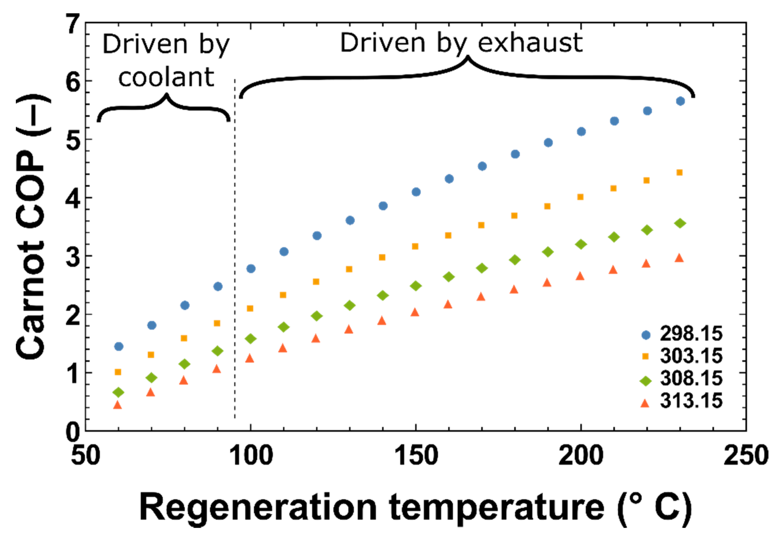
Figure 3 shows the Carnot COPs of the adsorption cycle for various temperatures of the heat source and the intermediate reservoir. Here, the temperature of the evaporator is kept constant at 5 °C. In automobile applications, the heat source temperature can be classified as the engine coolant below 100 °C and the exhaust gas above 100 °C. It is noted that the effect of the temperature for the heat rejection (adsorption and condensation heat) on the COP is less significant for a heat source temperature below 100 °C as compared to those above 100 °C. The Carnot COP is independent of the working pair and irreversibilities associated with the cycle. Hence, the COPs of practical adsorption cycles are lower than the Carnot COP. The COP of a typical single-effect adsorption cycle without the recycling of heat is approximately 0.3–0.4 [22]. Lambert and Jones highlighted that the COP could be improved to around 0.65 by recovering ~40% in a two-bed device using uniform temperature heat recovery [6]. As highlighted by Shelton et al., 40% recovery is the practical limit while the theoretical ceiling is ~50% [23]. On the other hand, the system COP of 1.2 was demonstrated by 75 to 80% in a thermal wave regeneration scheme [24,25]. As mentioned before, the COP of the adsorption heat pumps varies depending on the choice of a working pair. The performance of adsorption heat pumps for several working pairs based on the equilibrium cycle analysis can be found elsewhere [26,27,28,29,30].
The specific cooling power (SCP) is often expressed as (i) mass-based in kW/kg and (ii) volume-based, i.e., kW/m3. The mass-based SCP is usually employed for solid adsorbents in pellet forms while the volume-based SCP is adopted for very fine powder and composite adsorbents. It should be highlighted here that two different kinds of denominator of SCP, i.e., the mass or the volume, are usually encountered in the literature depending whether the “dead mass” is counted or not. Here, the “dead mass” refers to other structural components such as heat exchanger and the shell of the chamber which do not participate in the adsorption process. When assessing the performance of a particular adsorbent, the SCP using the dry mass of the adsorbent is convenient since it is sometimes problematic to estimate the total mass of the adsorber heat exchanger. Dry mass- or volume-based SCP is the preferred performance parameter for the studies based on isotherm properties of the adsorbent. However, dry mass- or volume-based SCP might provide an erroneous impression when the adsorption system is investigated for the replacement of other systems such as a mechanical vapour compression (MVC) system or an absorption system. For such scenarios, the total mass- or volume-based SCP should be employed for a fair comparison. Thus, herein, the dry mass- or volume-based specific cooling power will be termed as SCPd, while the total mass- or volume-based specific cooling power will be termed as SCPt. The SCPd depends on the nature of the isotherm and the thermophysical properties of the adsorbent + adsorbate pair such as the specific surface area and the micropore volume. Meanwhile, the SCPt is further influenced by the heat and mass transfer characteristics such as the thermal conductivity, porosity and permeability of the adsorber bed as well as the interface resistance between the adsorbent and the heat exchanger. Thus, Lambert and Jones [6], as referenced by Saha et al. [31] and Cerkvenik et al. [32], stressed that improving the ratio of the adsorbent mass to the non-adsorbent mass and the NTU of the heat exchanger are crucial for improved COP of the adsorption systems.
4. Adsorbent Materials
Adsorption heat pumps utilise the differential chemical potential of the porous solids. The sorption potential of the regenerated adsorbent is utilised in the adsorption process while the desorption process restores this chemical potential. Thus, the adsorbent material can be considered as the bottleneck of the adsorption heat pumps. Generally, porous materials with a huge specific surface area (typically > 500 m2/g) are employed as adsorbents. Other important characteristics of the adsorbent materials are thermophysical properties such as porosity, pore volume (micro, meso, and macro), pore width, and pore size distribution, as well as the polarity, surface heterogeneity, hydrophobicity, and hydrophilicity. Meanwhile, adsorption heat pumps utilise chemisorption and physisorption processes. Moreover, the performance of a particular adsorbent may depend on the type of adsorbate (the refrigerant). Regardless of the nature of adsorbate, i.e., the refrigerant, the high surface area is always preferable in adsorption heat pumps. The temperature of the recoverable heat in automobiles varies in a wide range (between 50 and 800 °C), as such, most adsorbent materials can generally be applied. Nevertheless, various adsorbents can be readily grouped as (i) carbon-based, (ii) silica-based, (iii) zeolite and molecular sieve-based, and (iv) metal organic frameworks (MOFs). Table 3 lists commonly-used adsorbents along with their porous characteristics that are widely studied in the research field of adsorption heat pumps with potential for automobile applications.
5. Adsorbate/Refrigerant
Adsorption systems utilise adsorbate/refrigerants as working fluids. Natural or environmentally friendly refrigerants are often adopted in adsorption systems where the choice of refrigerant is influenced by the performance merits such as the latent heat and net uptake by a particular adsorbent. For applications in automobile air conditioning, the flammability and toxicity of the refrigerant are vital properties due to the mobile and hazardous nature involved. Refrigerants also dictate the operating pressure which might vary from partial vacuum to several atmospheres. Table 4 gives some refrigerants and their important properties relevant to the adsorption systems in automobiles. Table 4 highlights that refrigerants with high volumetric capacity operate at high pressure and exhibit low-pressure ratio and small specific volume. Large specific volume enacts bulkiness in the heat exchanger and vapour duct design. Despite such a wide range of available refrigerants for the adsorption system in an automobile, water, ethanol, and methane can be considered as proven refrigerants whilst R134a has been applied in conventional MVC systems.
6. Practical Aspects and Performance Tests
Adsorption heat pumps employ a particular adsorbent/adsorbate pair, while adsorption chillers were commercialised in Japan several decades ago [61]. Most adsorption systems utilise multibed schemes such as two-bed, three-bed, four-bed, and six-bed arrangements [62,63,64,65,66,67]. Several publications on the operating procedures and the state of the art of such systems are available in the open literature. Interested readers may refer to the works of Suzuki et al. [68], Saha et al. [69], Wu et al. [70], Thu et al. [21,71,72] and to name a few. The performance of a typical air conditioning system installed on an automobile depends on the driving modes, such as urban driving and highway driving. This is mainly because the driving mode dictates the quantity and quality of the available waste heat from the engine. On the other hand, the cooling load is influenced by several factors such as the meteorological conditions and the number of people on board. Further note that adsorption systems operate in cyclic-steady mode and hence the fluctuation in the cooling energy, consequently, the cabin air temperature oscillation is inevitable. Therefore, the experimental investigation and performance assessment of adsorption cooling systems operating under the actual driving conditions are crucial steps to realise the widespread adoption of adsorption systems in the automobile industry. Experimental investigations using a prototype on a vehicle might involve several technical challenges such as the modification of the engine compartment and coolant circuit, the allocation and installation of the additional air-cooled radiators, obtaining road-worthiness approval, and achieving high compactness, robust control for the safe operation and to name a few. Thus, the performance evaluation of adsorption cooling systems for automobiles can be readily categorised into (i) numerical experiments mimicking the actual heat source, (ii) experiments on prototypes such as using a wind tunnel or simulated heat source temperature, and (iii) performance investigation under actual driving conditions on a road test. Due to the unique nature of the operating environment, conventional performance results based on the stationary or landed systems, such as adsorption chillers or heat pumps, should not be regarded as being totally relevant to automobile air conditioning despite that performance investigations (both numerical and experimental) for such systems are abundantly reported in the literature. Key differences lie in the driving mode-dependent heat source, air-cooled heat transfer mechanism (adsorption and condensation), and the significant heat leak compared to small capacity [73]. A review on the design of adsorber heat exchangers in vehicle air-conditioning was conducted by Sharafian et al. [74]. Nine types of adsorber heat exchanger design, namely (1) Spiral plate, (2) Shell and tube, (3) Hairpin, (4) Annulus tube, (5) Plate fin, (6) Finned tube, (7) Plate-tube, (8) Simple tube, and (9) Plate, were described together with the performance results in terms of the COP and SCPd. Hairpin type heat exchangers were reported to exhibit the highest COP while the plate type offered the best SCPd. On the other hand, annulus tube, fin tube, and plate tube configurations showed a high adsorbent mass to heat exchanger (bed) mass ratio. Tamainot-Telto et al. reported the development of a novel compact adsorber regenerator achieving a packing density of 435 kg/m3 with the adsorbent mass of 1 kg, while the total weight of the bed is reported to be 9 kg [75].
6.1. Numerical Experiments Mimicking the Actual Heat Source
Numerical models on adsorption cooling systems for automobile air-conditioning can be considered more or less the same as models developed for a typical adsorption chiller. In contrast to most adsorption chillers, a direct water-cooled condenser is irrelevant while the constant temperature for the heat source is almost unattainable. Thus, a proper mathematical model for an adsorption system to be employed in automobiles should address the heat transfer mechanism between the air and the heat exchangers, heat leak as well as the heat source profiling. Consequently, this review excludes models on water-cooled systems that do not address air-side heat transfer since they are irrelevant to automobile air conditioning despite their titles said otherwise. On the other hand, Mitra et al. have developed numerical models for a two-stage adsorption chiller using air-cooled heat exchangers for the adsorbers and the condenser [76]. Such systems are not suitable for automobile application; however, the developed model can be applied for automobile adsorption systems. Table 5 summarises the development and investigation of numerical experiments on adsorption systems specifically for automobile application with the relevant operation and design constraints.
6.2. Experiments on Prototypes
One of the important steps for the widespread usage of adsorption systems for automobiles is the performance evaluation and confirmation on prototypes. These prototypes drastically differ from immobile adsorption systems/chillers in many aspects such as design compactness, vapour duct layout, and the arrangement of the evaporator and the condenser units. Figure 4 shows the 3D model of a compact adsorption system designed for the automobile air conditioner. In this design, the evaporator and the condenser are placed under the adsorber beds with short vapour ducts and valves commuting between them. The differential pressure between the condenser and the evaporator is maintained using a control (expansion) valve instead of a U-tube which is often used in adsorption chiller where the condenser is placed at a higher elevation, mostly, on top of the adsorber beds. A prototype unit was constructed using polymer + water as the working sorption pair. Table 6 gives the detailed specifications of the present prototype.
The performance of the prototype unit was evaluated by the wind tunnel tests. Two kinds of driving modes were selected, namely (a) constant speed and (b) JC08 model [80]. Detailed experimental conditions are given in Table 7.
The cooling power of the system is evaluated at two different locations; the cooling power at the evaporator (QEvap) and the net cooling load at the vehicle cabin (QCabin) via the inlet and outlet air streams. Figure 5 shows the performance of the adsorption system prototype under the constant driving speed of 40 km/h (Test no. 1). In this test, a constant solar load of 1.0 kW/m2 is supplied to the cabin. The batch-nature of the adsorption system is reflected in the cooling power profile of the evaporator. The transient cooling power varies between 1.09 and 2.18 kW with the average value of 1.51 kW. On the other hand, the cabin cooling power is observed to be slightly lower than the evaporator cooling power fluctuating between the lower trough and peak (1.06 and 1.13). The slightly lower cooling power may be due to the heat leak from the engine compartment, and lower cooling power extremes could be attributable to the thermal masses in the cabin. The average net cooling power is found to be around 1.13 kW which is about 75% of the evaporator cooling load. The weight-based energy density (SCPt) is about 56.5 W/kg.
Figure 6 shows the performance under Test no. 2 where the solar load input was removed. Here the average cooling loads of the evaporator and the cabin are observed to be 1.19 kW and 0.98 kW. It is noted that these cooling load values are lower than the results recorded in Test no. 1 where the input solar load of 1.0 kW leads to the rise in the evaporating temperature, subsequently, the cooling power. The net cabin cooling load is about 82% of the evaporator cooling load which is due to the lower ambient, i.e., 25 °C, and cabin temperatures.
The performance results under JC08 driving mode (Test no. 3) are given in Figure 7. The variation in the temperature of the engine coolant is depicted as well. The maximum, minimum and the average temperatures of the hot water are logged to be 94.0, 69.0, and 81.6 °C, respectively. This temperature variation results from the changes in the engine speed under the JC08 driving mode. The average evaporator cooling capacity is 1.15 kW, and that of the cabin is 0.96 kW. It is noteworthy that the cooling load variations in all three tests seemed rather lenient despite the batch-nature of the adsorption process. Extreme variations in the cooling load and cabin temperature are not preferable, and here the results showed that the cooling load matching between the adsorption system and the cabin could serve as an important parameter.
The efficacy of the adsorption air conditioning system as compared to the mechanical vapour compression (MVC) system is assessed in terms of the fuel economy. Fuel economy tests were conducted under the driving condition (JC08 mode) while driving without operating any air conditioning system was kept as the baseline. The actual fuel consumptions under each test condition were recorded and evaluated using the automobile/car shown in Figure 4c. The fuel consumption by operating the onboard MVC chiller was then measured. Tests were performed using the adsorption system operated by the engine waste heat. The normalised fuel economy values of these tests were depicted in Figure 8. From Figure 8 it can be observed that the usage of the MVC system for the vehicle air conditioning leads to ~8% reduction in the fuel economy while this figure reduces to ~1% when the adsorption system is employed as the replacement. This result reflects the logic behind the benefit of the waste heat recovery and the savings in the engine power output used for operating the MVC system.
6.3. Performance Investigation under Actual Driving Conditions on a Road Test
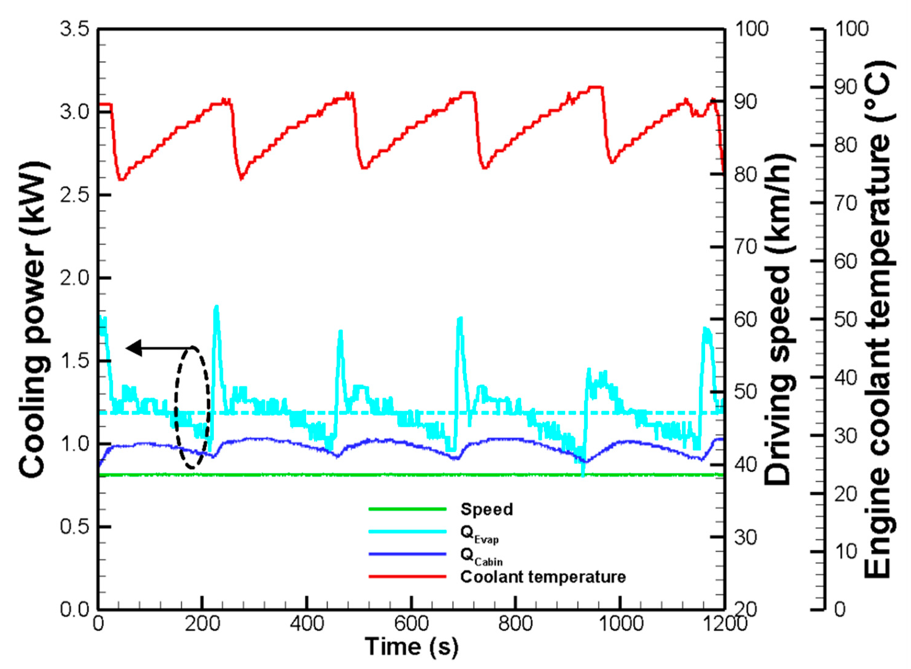
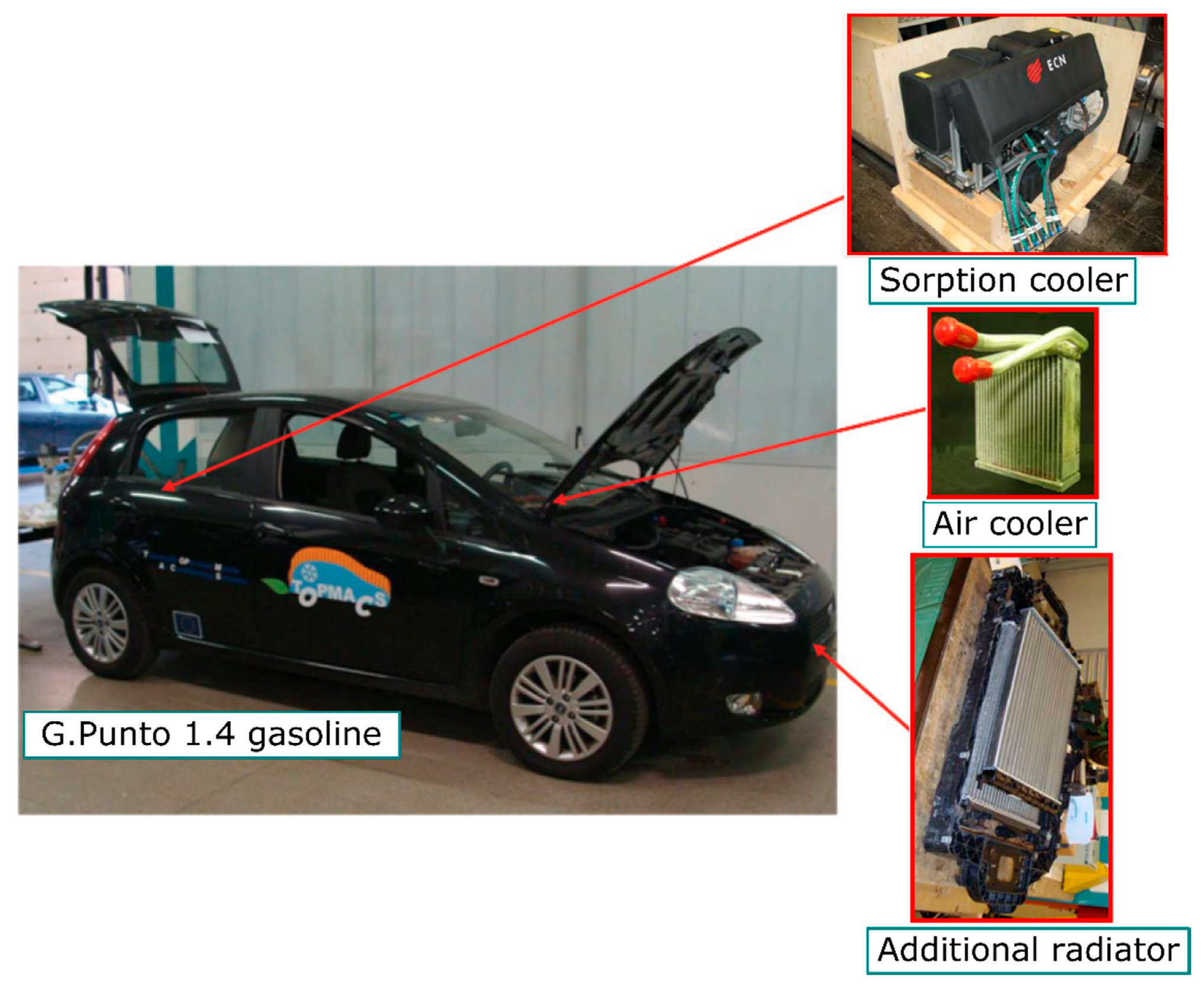
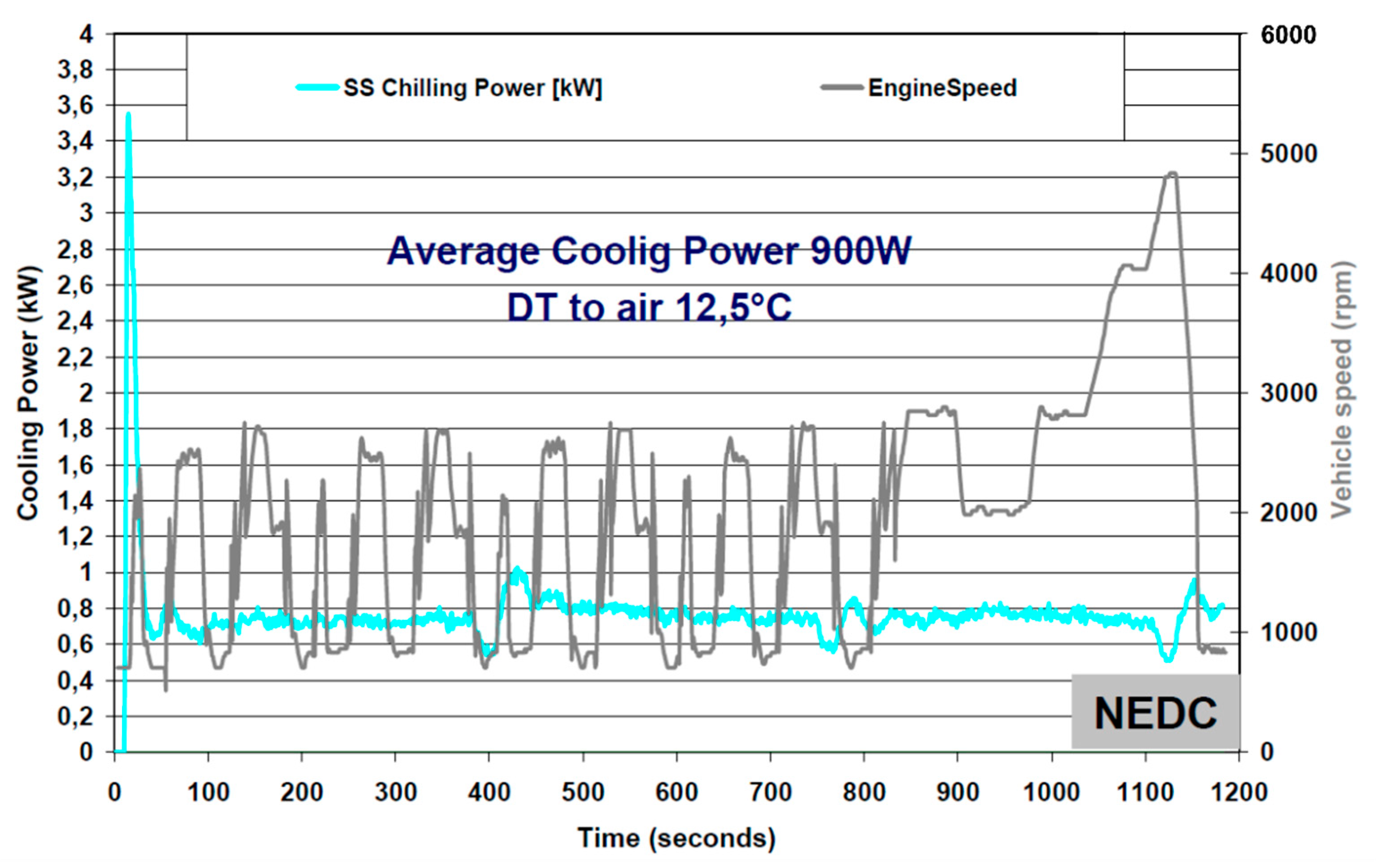
Onboard tests under real driving conditions are essential steps for widespread adoption of adsorption systems in automobiles. Magnetto et al. reported the performance of the adsorption systems installed on a European B-segment compact car (Fiat Grande Punto) [8]. The silica gel-based adsorption unit was installed in the trunk of the car. The additional radiator for the rejection of the adsorption and condensation heat is installed in the engine bay. The pictorial view of the test vehicle and components are reprinted in Figure 9. The authors conducted tests under various conditions such as constant driving speed, different air temperatures, the NEDC (Normalized European Driving Cycle), and the Start/Stop engine operation. As shown in Figure 10, the adsorption system was able to produce more or less stable cooling power (0.8–0.9 kW) at various engine speeds. Such invariant cooling power was attributed to the thermal inertia or the thermal mass of the adsorption system and the heat source, i.e., the engine cooling water circuit. The authors proposed a small burner as an auxiliary heating system for the adsorption system during engine shut off or situations where the vehicle was parked under the sun.
Magnetto et al. further developed adsorption systems using zeolite + water pair and conducted field tests with this system installed on a Stralis truck produced by IVECO [8]. The system employed ~2 kg of Zeolite-based FAM-Z02 packed with the fin-tube heat exchanger which lead to a very compact package of 170 dm3. The pictorial views of the adsorption system installed on the cabin of the track are reprinted in Figure 11. The field test results under the nominal driving condition showed that the adsorption system is capable of producing the cooling power of 1 to 2.3 kW at a COP of 0.25 to 0.45. The specific cooling capacity (SCPd) is reported to be 300 to 600 W/kg when operating at heat source and condensation temperatures of 90 °C and 28 °C, respectively. The temporal temperatures of the major components and the cabin are reproduced in Figure 12. It is reported that the produced cooling capacity was about 3 kW under the air recirculation mode while the air flow speed was 600 CMH.
Verde et al. evaluated the performance of an adsorption system recovering the waste heat from the automotive under real driving conditions. The adsorption unit was installed on a Fiat Grande Punto car, and tests for various driving cycles (different ambient and start-up conditions) were performed in a climatic chamber. The climatic chamber was able to simulate the desired ambient air temperature, air flow, and solar radiation input. The Normal European Driving Cycle (NEDC) was adopted. The study highlights relatively high cabin temperature due to the lack of thermal energy (waste heat) at the start-up mode. The remedy to shorten the start-up delay was to send the water back to the engine resulting variation in the temperature and the mass flow rates to the adsorption system. Figure 13 reproduces the variations in the engine speed and the cabin temperature, particularly, the time to get the cabin cooling at the start-up conditions, under the NEDC-2ECE (ECE: elementary urban cycles at low speed) cycle. Three performance tests under NEDC mode, namely (1) the equivalent European summer conditions (28 °C and 50% RH), (2) severe summer conditions (35°C and 60% RH), and (3) cool-down test (42 °C and 35% RH) were experimented. The nominal parameters for the operation of the adsorption systems were: the inlet temperature and the flow rate of the hot water were 90 °C and 0.2 kg/s, the cooling water inlet temperature and the flow rate (both adsorber and the condenser) were 33 °C and 0.2 kg/s, while the chilled water inlet temperature was kept at 15 °C with a flow rate of 0.13 kg/s. Optimal cycle times for the constant heat source temperature were evaluated at different air temperatures. It was reported that the optimum cycle time is ~700 s (656 s) when the ambient temperature is set at 28 °C; the cooling capacity and COP were recorded to be 1.46 kW and 0.34, respectively. The authors concluded that the waste heat from the engine coolant was enough to operate the adsorption system. The performance figures under the Equivalent European summer conditions were reported to be 0.925 W while the COP is ~0.4.
7. Future Aspects and Tasks on Adsorption Systems for Automobile Air Conditioning
The amount of waste heat available from the automobile engine and the basic characteristics of adsorption systems, i.e., the ability to operate using the waste heat, portray enormous potential for improved fuel economy and environmental friendliness. However, despite such obvious benefits and prospects, the widespread usage of adsorption systems has not been realised thus far. It is another obvious fact that adsorption systems/chillers have been around for several decades (in fact earlier than the mechanical vapour compression (MVC) systems) and they are unable to replace the MVC systems. The application of adsorption systems in automobile air conditioning enjoys the readily available waste heat which is going to be severely affected by the emergence of electric vehicles. However, IC engine-driven vehicles will still be on the road for the foreseeable future, and the successful emergence of adsorption cooling systems for automobile air conditioning might revive the industry with improved fuel economy and environmental friendliness. On the other hand, it is crucial to treat vehicle adsorption systems in a different domain separated from the so-called adsorption chillers which are mostly stationary or immobile and sometimes free from space and weight limitations Some key challenges to automobile adsorption systems are listed as follows:
- (i)
- Energy density (W/kg or W/m3): The energy density of adsorption systems used to be extremely poor. The industry has adopted some salient developments such as (1) the adaptation of compact vapour duct and valve designs, (2) compact adsorber heat exchanger, (3) the usage of expansion valves replacing the U-bend, and (4) the introduction of composite adsorbent. The reported energy density values are 102 W/kg (total mass of the adsorption unit) [77], 33–50 W/kg [78], and 55–75 W/kg (based on the results from Figure 5). Note, however, that the energy density of a typical MVC system is ~526 W/kg [77]. When it comes to the volumetric energy density of adsorption systems, the reported values are 11.8 to 17.6 W/m3 [78] and 19.82 to 26.49 W/m3 (based on the results from Figure 3 and Figure 4). Thus, the energy density of adsorption systems must be improved. Composite adsorbents have been developed for improved thermal conductivity yet most of the reported works focus on elementary isotherm or kinetic studies. Wang et al. reported an experimental unit on a resorption cycle for vehicles using the composite adsorbent with a MnCl2–CaCl2 working pair. The unit has a cooling capacity of 3 kW, and the packing density of the composite was estimated to be 300 kg/m3. Note, however, that this figure is not based on the overall volume of the refrigeration system [82]. Here, it should be stressed that the conventional terminologies, such as the specific cooling energy (SCE) or specific cooling power (SCP) based on the dry mass, are not helpful or, sometimes, give the wrong impression. Instead, the specific energy density based on the total mass or the volume of the system should be applied, and most importantly, apple-to-apple comparison with the conventional MVC system should be adopted when appropriate.
- (ii)
- Reliability evaluation: Adsorption systems are reported to be operational for several years, for example, the adsorption prototype in the Air Conditioning Laboratory of the National University of Singapore has been operating since 2002 [83,84,85]. Belding et al. studied ageing and its effect on the desiccant cooling performance for 50,000 cycles [86]. Note, however, that these systems are not for automobile air conditioning. The operational environment of the adsorption systems on an automobile can be subjected to vibration, sudden impacts, and high temperature surroundings. The vibrating condition might damage the adsorber heat exchanger. Thus, sintered or firmly coated adsorber heat exchangers might be preferable to the conventional wire-mesh packing method. On the other hand, the high temperature environment negatively affects the adsorption process which strongly depends on the coolant temperature. Furthermore, most vehicles might be road worthy for several years, for example, the nominal operation year of a car in Singapore is ten years while the vehicle might be on the road for several decades in many parts of the world.
- (iii)
- Safety aspect: Adsorption systems can be considered relatively safe for a landed installation. However, the vehicular environment is prone to hazards such as fire and explosion which might result from collision or accidents. Moreover, equipment installed on a vehicle is subjected to stringent regulations such as the National Highway Traffic Safety Administration. The amount of refrigerant required for pool boiling or spray boiling in the evaporator might create extra risk for some flammable refrigerants such as ethanol and methanol.
- (iv)
- Cost aspect: Adsorption systems tend to be expensive. The MSRP (the Manufacturer’s Suggested Retail Price) of a subcompact vehicle may vary from 13,000 to 36,000 $ [87]. The average cost breakdown is reported to be material (50%), labour (9%), main machine (12%), overhead labour cost (10%), maintenance (5%), tooling cost (7%), and energy (6%) [88]. So, thus far, no information is available or kept as trade secrets on the cost breakdown of adsorption systems for car air conditioning. Nevertheless, from the above information, the acceptable ballpark cost for a car adsorption system can be estimated.
- (v)
- Involvement and support of the car manufacturing industry: The development of adsorption systems for automobile air-conditioning is, hitherto, laboratory or project-based research. Active involvement and support from the car manufacturing industry are essential to move forward and gain widespread acceptance.
- (vi)
- Regulation and Incentives: Support and incentives from the authorities are crucial in pushing new technologies. Renewable energy technologies such as wind, solar PV cells, and even hybrid vehicles gained acceptance with the help of incentives at their initial introduction and adsorption systems for automobile air conditioning is not an exception as well.
The comparison of the various aspects of adsorption systems and conventional MVC systems for automobile air conditioning are depicted in Figure 14. From Figure 14, adsorption systems seem to be inferior to the conventional MVC systems in many aspects. However, the most important features of the adsorption system are the potential to improve fuel economy and environmental friendliness. Nonetheless, such potentials cannot be realised without addressing other impediments while improved energy density and durability can be considered as the keys to successful widespread usage. Internal combustion engine-driven vehicles still form the majority of vehicles on the roads while the number of electric vehicles is increasing daily. Electric vehicles no longer have the waste heat while the energy rejection by the battery packs might not have the same quality as the engine waste heat. In such scenarios, the widespread usage of adsorption systems in automobiles might be further thwarted. However, pioneering research works on sorption systems for electric vehicles have been reported by some researchers: Wang et al. analysed various working pairs for resorption-based air conditioners for electric vehicles [89] and Jiang et al. conducted the performance analysis of sorption system for the air conditioning of electric vehicles, notably for cooling in summer and heating in winter [90,91].
8. Conclusions
Demand for cabin thermal comfort and the availability of waste heat from internal combustion engines set favourable conditions for adsorption systems. However, the implementation of adsorption systems in automobiles can be considered to be in its infancy since almost no car is utilising such a system in practice. Improvements in the energy density and real-world test results are essential for further progress and the realisation of widespread usage of adsorption systems in vehicles. There remain several unknowns or challenges such as meeting tight safety aspect, performance stability, durability level, and economic feasibility. Developments in adsorption chiller industry are often reported or depicted as relevant progress in automobile air conditioning. Adopting the performance indicators normally used in landed or immobile adsorption heat pump industry such as specific cooling energy (SCE) or specific cooling power (SCP) are unhelpful or even might disguise as actual progress because these parameters are based on the dry mass of the adsorbent. The compactness and light weight of the adsorption systems as a whole package is crucial for better fuel economy. Hence, improved and concise performance parameters should be employed instead. Adsorption systems for automobile air conditioning are in a separate league and demand special yet specific and focused research. The emergence and pervasive acceptance of electric vehicles chop away the waste heat availability and might further setback the adaptation of adsorption systems. Nevertheless, due to the current limitations, such as readiness of the grid and charging stations, IC engine-driven vehicles might still be running on the roads for the foreseeable future. Thus, expedited development and progress, along with regulatory support such as green incentives, are essential for the realisation of adsorption systems for automobile air conditioning.
Author Contributions
S.M. and T.M. (Tomohiro Maruyama) designed and conducted the experiments. Conceptualization: K.T. and T.M. (Takahiko Miyazaki). The manuscript was written by S.M., and K.T. and edited by T.M. (Takahiko Miyazaki).
Funding
This research was funded by the Thermal Management Materials and Technology Research Association (TherMAT), and New Energy and Industrial Technology Development Organization (NEDO), Japan.
Acknowledgments
The second author of the present work further acknowledges the Kyushu University Program for Leading Graduate School, Green Asia Education Center for their support in conducting this study.
Conflicts of Interest
The authors declare no conflicts of interest.
Nomenclature
| COP | the coefficient of performance (-) |
| COPC | Carnot COP (-) |
| MVC | mechanical vapour compression |
| p | pressure (kPa) |
| q | equilibrium uptake (kg/kg) |
| Q | thermal energy (J) |
| qVol | volumetric capacity (kJ/m3) |
| SCE | specific cooling energy (kJ/kg) |
| SCP | specific cooling power (W/kg, W/m3) |
| T | temperature (C, K) |
| Subscripts | |
| a | adsorption |
| c | condenser |
| cond | condenser |
| d | desorption/dry mass based |
| e | evaporator |
| evap | evaporator |
| max | maximum |
| min | minimum |
| t | total |
References
- United Nations Depeartment of Economic and Social Affairs. 2018 Revision of World Urbanization Prospects. Available online: https://www.un.org/development/desa/publications/2018-revision-of- world-urbanization-prospects.html (accessed on 26 September 2018).
- Oica. World Motor Vehicle Production by Country and Type. 2017. Available online: http://www.oica.net/wp-content/uploads/By-country-2017.pdf (accessed on 26 September 2018).
- Japan Automobile Manufacturers Association Inc. The Motor Industry of Japan 2018. Available online: http://www.jama-english.jp/publications/MIJ2018.pdf (accessed on 26 September 2018).
- Baglione, M.L. Development of System Analysis Methodologies and Tools for Modeling and Optimizing Vehicle System Efficiency. Ph.D. Thesis, University of Michigan, Ann Arbor, MI, USA, 2007. [Google Scholar]
- Japan’s National Greenhouse Gas Emissions in Fiscal Year 2016. Available online: https://www.nies.go.jp/whatsnew/20180424/20180424-e.html (accessed on 26 September 2018).
- Lambert, M.A.; Jones, B.J. Automotive Adsorption Air Conditioner Powered by Exhaust Heat. Part 1: Conceptual and Embodiment Design. Proc. Inst. Mech. Eng. Part D J. Automob. Eng. 2006, 220, 959–972. [Google Scholar] [CrossRef]
- Hughes, J. Toyota Develops World’s Most Thermally Efficient 2.0-Liter Engine—The Drive. Available online: http://www.thedrive.com/tech/18919/toyota-develops-worlds-most-thermally-efficient-2-0-liter -engine (accessed on 2 October 2018).
- Magnetto, D.; Boer, D.R.; Vasta, S. TOPMACS: Thermally OPerated Mobile Air Conditioning Systems. In Vehicle Thermal Management Systems Conference and Exhibition (VTMS10); Elsevier: New York, NY, USA, 2011; pp. 635–647. [Google Scholar]
- Saidur, R.; Rezaei, M.; Muzammil, W.K.; Hassan, M.H.; Paria, S.; Hasanuzzaman, M. Technologies to recover exhaust heat from internal combustion engines. Renew. Sustain. Energy Rev. 2012, 16, 5649–5659. [Google Scholar] [CrossRef]
- Zhao, W.Z.; Sun, T.; Grattan, K.T.V.; Wei, C.L.; Al-Shamma′a, A.I. Temperature monitoring of vehicle engine exhaust gases under vibration condition using optical fibre temperature sensor systems. J. Phys. Conf. Ser. 2006, 45, 215. [Google Scholar] [CrossRef]
- Fu, J.; Liu, J.; Feng, R.; Yang, Y.; Wang, L.; Wang, Y. Energy and exergy analysis on gasoline engine based on mapping characteristics experiment. Appl. Energy 2013, 102, 622–630. [Google Scholar] [CrossRef]
- Myat, A.; Kim Choon, N.; Thu, K.; Kim, Y.D. Experimental investigation on the optimal performance of Zeolite-water adsorption chiller. Appl. Energy 2013, 102, 582–590. [Google Scholar] [CrossRef]
- Wang, R.Z.; Oliveira, R.G. Adsorption refrigeration-An efficient way to make good use of waste heat and solar energy. Prog. Energy Combust. Sci. 2006, 32, 424–458. [Google Scholar] [CrossRef]
- Sami, S.M.; Tribes, C. An improved model for predicting the dynamic behaviour of adsorption systems. Appl. Therm. Eng. 1996, 16, 149–161. [Google Scholar] [CrossRef]
- Chakraborty, A.; Thu, K.; Saha, B.B.; Ng, K.C. Adsorption-Desalination Cycle. In Advances in Water Desalination; Lior, N., Ed.; John Wiley and Sons: New York, NY, USA, 2012; pp. 377–451. [Google Scholar]
- Thu, K.; Kim, Y.-D.; Shahzad, M.W.; Saththasivam, J.; Ng, K.C. Performance investigation of an advanced multi-effect adsorption desalination (MEAD) cycle. Appl. Energy 2015, 159, 469–477. [Google Scholar] [CrossRef]
- Aristov, Y. Concept of adsorbent optimal for adsorptive cooling/heating. Appl. Therm. Eng. 2014, 72, 166–175. [Google Scholar] [CrossRef]
- Aristov, Y.I.; Glaznev, I.S.; Girnik, I.S. Optimization of adsorption dynamics in adsorptive chillers: Loose grains configuration. Energy 2012, 46, 484–492. [Google Scholar] [CrossRef]
- Aristov, Y.I. Adsorptive transformation and storage of renewable heat: Review of current trends in adsorption dynamics. Renew. Energy 2017, 110, 105–114. [Google Scholar] [CrossRef]
- Gordon, J.M.; Ng, K.C. Cool Thermodynamics: The Engineering and Physics of Predictive, Diagnostic and Optimization Methods for Cooling Systems; Cambridge International Science Publishing: Great Abington, Cambridge, UK, 2000. [Google Scholar]
- Thu, K.; Kim, Y.-D.; Myat, A.; Chun, W.G.; NG, K.C. Entropy generation analysis of an adsorption cooling cycle. Int. J. Heat Mass Transf. 2013, 60, 143–150. [Google Scholar] [CrossRef]
- Lambert, M.A.; Jones, B.J. Review of Regenerative Adsorption Heat Pumps. J. Thermophys. Heat Transf. 2005, 19, 471–485. [Google Scholar] [CrossRef]
- Shelton, S.V.; Wepfer, W.J.; Miles, D.J. Ramp Wave Analysis of the Solid/Vapour Heat Pump. J. Energy Resour. Technol. 1990, 112, 69–78. [Google Scholar] [CrossRef]
- Tchernev, D.I.; Emerson, D.T. High efficiency regenerative zeolite heat pump. ASHRAE Trans. 1988, 94, 2024–2029. [Google Scholar]
- Tchernev, D.I. Regenerative Zeolite Heat Pump. Stud. Surf. Sci. Catal. 1989, 49, 519–526. [Google Scholar] [CrossRef]
- Azahar, F.H.M.; Mitra, S.; Yabushita, A.; Harata, A.; Saha, B.B.; Thu, K. Improved model for the isosteric heat of adsorption and impacts on the performance of heat pump cycles. Appl. Therm. Eng. 2018, 143, 688–700. [Google Scholar] [CrossRef]
- Boman, D.B.; Hoysall, D.C.; Pahinkar, D.G.; Ponkala, M.J.; Garimella, S. Screening of working pairs for adsorption heat pumps based on thermodynamic and transport characteristics. Appl. Therm. Eng. 2017, 123, 422–434. [Google Scholar] [CrossRef]
- Uddin, K.; El-sharkawy, I.I.; Miyazaki, T. Thermodynamic Analysis of Adsorption Cooling Cycle using Ethanol-Surface treated Maxsorb III Pairs. Evergreen Jt. J. Novel Carbon Resour. Sci. Green Asia Strategy 2014, 1, 25–31. [Google Scholar]
- Pal, A.; El-Sharkawy, I.I.; Saha, B.B.; Jribi, S.; Miyazaki, T.; Koyama, S. Experimental investigation of CO2 adsorption onto a carbon based consolidated composite adsorbent for adsorption cooling application. Appl. Therm. Eng. 2016, 109, 304–311. [Google Scholar] [CrossRef]
- Loh, W.S.; El-Sharkawy, I.; Ng, K.C.; Saha, B.B. Adsorption cooling cycles for alternative adsorbent/adsorbate pairs working at partial vacuum and pressurized conditions. Appl. Therm. Eng. 2009, 29, 793–798. [Google Scholar] [CrossRef]
- Saha, B.B.; Akisawa, A.; Kashiwagi, T. Thermodynamic analysis of adsorption refrigeration cycles. In Proceedings of the 32nd Intersociety Energy Conversion Engineering Conference, Honolulu, HI, USA, 27 July–1 August 1997; IEEE: Piscataway Township, NJ, USA, 1997. [Google Scholar]
- Cerkvenik, B.; Poredoš, A.; Ziegler, F. Influence of adsorption cycle limitations on the system performance. Int. J. Refrig. 2001, 24, 475–485. [Google Scholar] [CrossRef]
- Saha, B.B.; Koyama, S.; El-Sharkawy, I.I.; Kuwahara, K.; Kariya, K.; Ng, K.C. Experiments for measuring adsorption characteristics of an activated carbon fiber/ethanol pair using a plate-fin heat exchanger. HVAC R Res. 2006, 12, 767–782. [Google Scholar] [CrossRef]
- Saha, B.B.; El-Sharkawy, I.I.; Chakraborty, A.; Koyama, S.; Yoon, S.H.; Ng, K.C. Adsorption rate of ethanol on activated carbon fiber. J. Chem. Eng. Data 2006, 51, 1587–1592. [Google Scholar] [CrossRef]
- Hamamoto, Y.; Alam, K.C.A.; Saha, B.B.; Koyama, S.; Akisawa, A.; Kashiwagi, T. Study on adsorption refrigeration cycle utilizing activated carbon fibers. Part 1. Adsorption characteristics. Int. J. Refrig. 2006, 29, 305–314. [Google Scholar] [CrossRef]
- Himeno, S.; Komatsu, T.; Fujita, S. High-pressure adsorption equilibria of methane and carbon dioxide on several activated carbons. J. Chem. Eng. Data 2005, 50, 369–376. [Google Scholar] [CrossRef]
- Singh, V.K.; Kumar, E.A. Thermodynamic analysis of single-stage and single-effect two-stage adsorption cooling cycles using indigenous coconut shell based activated carbon-CO2 pair. Int. J. Refrig. 2017, 84, 238–252. [Google Scholar] [CrossRef]
- Rahman, K.A.; Chakraborty, A.; Saha, B.B.; Ng, K.C. On thermodynamics of methane + carbonaceous materials adsorption. Int. J. Heat Mass Transf. 2012, 55, 565–573. [Google Scholar] [CrossRef]
- Singh, V.K.; Kumar, E.A. Experimental investigation and thermodynamic analysis of CO2 adsorption on activated carbons for cooling system. J. CO2 Util. 2017, 17, 290–304. [Google Scholar] [CrossRef]
- Thu, K.; Kim, Y.-D.; Ismil, A.B.; Saha, B.B.; Ng, K.C. Adsorption characteristics of methane on Maxsorb III by gravimetric method. Appl. Therm. Eng. 2014, 72. [Google Scholar] [CrossRef]
- Pal, A.; Kil, H.-S.; Mitra, S.; Thu, K.; Saha, B.B.; Yoon, S.-H.; Miyawaki, J.; Miyazaki, T.; Koyama, S. Ethanol adsorption uptake and kinetics onto waste palm trunk and mangrove based activated carbons. Appl. Therm. Eng. 2017, 122, 389–397. [Google Scholar] [CrossRef]
- Ng, K.C.; Chua, H.T.; Chung, C.Y.; Loke, C.H.; Kashiwagi, T.; Akisawa, A.; Saha, B.B. Experimental investigation of the silica gel-water adsorption isotherm characteristics. Appl. Therm. Eng. 2001, 21, 1631–1642. [Google Scholar] [CrossRef]
- Chua, H.T.; Ng, K.C.; Chakraborty, A.; Oo, N.M.; Othman, M.A. Adsorption characteristics of silica gel + water systems. J. Chem. Eng. Data 2002, 47, 1177–1181. [Google Scholar] [CrossRef]
- Li, A.; Thu, K.; Ismail, A. Bin; Shahzad, M.W.; Ng, K.C. Performance of adsorbent-embedded heat exchangers using binder-coating method. Int. J. Heat Mass Transf. 2016, 92, 149–157. [Google Scholar] [CrossRef]
- Thu, K.; Chakraborty, A.; Saha, B.B.; Ng, K.C. Thermo-physical properties of silica gel for adsorption desalination cycle. Appl. Therm. Eng. 2013, 50, 1596–1602. [Google Scholar] [CrossRef]
- Shen, Y.; Shi, W.; Zhang, D.; Na, P.; Fu, B. The removal and capture of CO2 from biogas by vacuum pressure swing process using silica gel. J. CO2 Util. 2018, 27, 259–271. [Google Scholar] [CrossRef]
- Yan, K.L.; Wang, Q. Adsorption characteristics of the silica gels as adsorbent for gasoline vapours removal. IOP Conf. Ser. Earth Environ. Sci. 2018, 153, 22010. [Google Scholar] [CrossRef]
- Yamk, R.; Yamk, U.; Heiden, C.; Daunt, J.G. Adsorption isotherms and heats of adsorption of neon and hydrogen on zeolite and charcoal between 20 and 90 K. J. Low Temp. Phys. 1981, 45, 443–455. [Google Scholar] [CrossRef]
- Deng, H.; Yi, H.; Tang, X.; Yu, Q.; Ning, P.; Yang, L. Adsorption equilibrium for sulfur dioxide, nitric oxide, carbon dioxide, nitrogen on 13X and 5A zeolites. Chem. Eng. J. 2012, 188, 77–85. [Google Scholar] [CrossRef]
- Abdul Kareem, F.A.; Shariff, A.M.; Ullah, S.; Mellon, N.; Keong, L.K. Adsorption of pure and predicted binary (CO2:CH4) mixtures on 13X-Zeolite: Equilibrium and kinetic properties at offshore conditions. Microporous Mesoporous Mater. 2018, 267, 221–234. [Google Scholar] [CrossRef]
- Ullah, R.; Saad, M.A.H.S.; Aparicio, S.; Atilhan, M. Adsorption equilibrium studies of CO2, CH4 and N2 on various modified zeolites at high pressures up to 200 bars. Microporous Mesoporous Mater. 2018, 262, 49–58. [Google Scholar] [CrossRef]
- Thu, K.; Kim, Y.-D.; Xi, B.J.; Ismail, A.B.; Ng, K.C. Thermophysical Properties of Novel Zeolite Materials for Sorption Cycles. Appl. Mech. Mater. 2013, 388, 116–122. [Google Scholar] [CrossRef]
- Kim, Y.-D.; Thu, K.; Ng, K.C. Adsorption characteristics of water vapour on ferroaluminophosphate for desalination cycle. Desalination 2014, 344, 350–356. [Google Scholar] [CrossRef]
- Teo, H.W.B.; Chakraborty, A.; Fan, W. Improved adsorption characteristics data for AQSOA types zeolites and water systems under static and dynamic conditions. Microporous Mesoporous Mater. 2017, 242, 109–117. [Google Scholar] [CrossRef]
- Teo, H.W.B.; Chakraborty, A.; Han, B. Water adsorption on CHA and AFI types zeolites: Modelling and investigation of adsorption chiller under static and dynamic conditions. Appl. Therm. Eng. 2017, 127, 35–45. [Google Scholar] [CrossRef]
- Xu, F.; Yu, Y.; Yan, J.; Xia, Q.; Wang, H.; Li, J.; Li, Z. Ultrafast room temperature synthesis of GrO@HKUST-1 composites with high CO2 adsorption capacity and CO2/N2 adsorption selectivity. Chem. Eng. J. 2016, 303, 231–237. [Google Scholar] [CrossRef]
- Férey, G.; Mellot-Draznieks, C.; Serre, C.; Millange, F.; Dutour, J.; Surblé, S.; Margiolaki, I. A Chromium Terephthalate-Based Solid with Unusually Large Pore Volumes and Surface Area. Science 2005, 309, 2040–2042. [Google Scholar] [CrossRef] [PubMed]
- Canivet, J.; Fateeva, A.; Guo, Y.; Coasne, B.; Farrusseng, D. Water adsorption in MOFs: Fundamentals and applications. Chem. Soc. Rev. 2014, 43, 5594–5617. [Google Scholar] [CrossRef] [PubMed]
- Myhre, G.; Shindell, D.; Bréon, F.-M.; Collins, W.; Fuglestvedt, J.; Huang, J.; Koch, D.; Lamarque, J.-F.; Lee, D.; Mendoza, B.; et al. Anthropogenic and Natural Radiative Forcing. In Climate Change 2013: The Physical Science Basis. Contribution of Working Group I to the Fifth Assessment Report of the Intergovernmental Panel on Climate Change; Cambridge University Press: Cambridge, UK, 2013; pp. 659–740. [Google Scholar]
- Bell, I.H.; Wronski, J.; Quoilin, S.; Lemort, V. Pure and Pseudo-pure Fluid Thermophysical Property Evaluation and the Open-Source Thermophysical Property Library CoolProp. Ind. Eng. Chem. Res. 2014, 53, 2498–2508. [Google Scholar] [CrossRef] [PubMed] [Green Version]
- Wang, X.; Chua, H.T. Two bed silica gel–water adsorption chillers: An effectual lumped parameter model. Int. J. Refrig. 2007, 30, 1417–1426. [Google Scholar] [CrossRef]
- Saha, B.B.; Koyama, S.; Kashiwagi, T.; Akisawa, A.; Ng, K.C.; Chua, H.T. Waste heat driven dual-mode, multi-stage, multibed regenerative adsorption system. Int. J. Refrig. 2003, 26, 749–757. [Google Scholar] [CrossRef]
- Chua, H.T.; Ng, K.C.; Malek, A.; Kashiwagi, T.; Akisawa, A.; Saha, B.B. Multibed regenerative adsorption chiller—Improving the utilization of waste heat and reducing the chilled water outlet temperature fluctuation. Int. J. Refrig. 2001, 24, 124–136. [Google Scholar] [CrossRef]
- Akahira, A.; Alam, K.C.A.; Hamamoto, Y.; Akisawa, A.; Kashiwagi, T. Mass recovery adsorption refrigeration cycle—Improving cooling capacity. Int. J. Refrig. 2004, 27, 225–234. [Google Scholar] [CrossRef]
- Thu, K.; Yanagi, H.; Saha, B.B.; Ng, K.C. Performance investigation on a 4-bed adsorption desalination cycle with internal heat recovery scheme. Desalination 2017, 402, 88–96. [Google Scholar] [CrossRef]
- Miyazaki, T.; Akisawa, A.; Saha, B.B. The performance analysis of a novel dual evapourator type three-bed adsorption chiller. Int. J. Refrig. 2010, 33, 276–285. [Google Scholar] [CrossRef]
- Thu, K.; Saha, B.B.; Chua, K.J.; Ng, K.C. Performance investigation of a waste heat-driven 3-bed 2-evapourator adsorption cycle for cooling and desalination. Int. J. Heat Mass Transf. 2016, 101, 1111–1122. [Google Scholar] [CrossRef]
- Suzuki, M. Adsorption Engineering; Elsevier: New York, NY, USA; Kodansha, Tokyo, 1990. [Google Scholar]
- Saha, B.B.; El-Sharkawy, I.I.; Chakraborty, A.; Koyama, S.; Ng, K.C. Study on single-and multi-stage adsorption cooling cycles working at sub and above atmospheric conditions. In Proceedings of the 2008 ASME International Mechanical Engineering Congress and Exposition, Boston, MA, USA, 31 October–6 November 2008; Volume 8, pp. 563–570. [Google Scholar]
- Wu, J.W.; Hu, E.J.; Biggs, M.J. Thermodynamic cycles of adsorption desalination system. Appl. Energy 2012, 90, 316–322. [Google Scholar] [CrossRef]
- Thu, K.; Kim, Y.-D.; Amy, G.; Chun, W.G.; Ng, K.C. A synergetic hybridization of adsorption cycle with the multi-effect distillation (MED). Appl. Therm. Eng. 2014, 62, 245–255. [Google Scholar] [CrossRef]
- Thu, K. Adsorption Desalination: Theory & Experiments. Ph.D. Thesis, National University of Singapore, Singapore, January 2010. [Google Scholar]
- Thu, K.; Takeda, N.; Miyazaki, T.; Saha, B.B.; Koyama, S.; Maruyama, T.; Maeda, S.; Kawamata, T. Experimental investigation on the performance of an adsorption system using Maxsorb III + ethanol pair. Int. J. Refrig. 2018. [Google Scholar] [CrossRef]
- Sharafian, A.; Bahrami, M. Assessment of adsorber bed designs in waste-heat driven adsorption cooling systems for vehicle air conditioning and refrigeration. Renew. Sustain. Energy Rev. 2014, 30, 440–451. [Google Scholar] [CrossRef]
- Tamainot-Telto, Z.; Metcalf, S.J.; Critoph, R.E. Novel compact sorption generators for car air conditioning. Int. J. Refrig. 2009, 32, 727–733. [Google Scholar] [CrossRef] [Green Version]
- Mitra, S.; Thu, K.; Saha, B.B.; Srinivasan, K.; Dutta, P. Modeling study of two-stage, multibed air cooled silica gel + water adsorption cooling cum desalination system. Appl. Thermal Eng. 2017, 114, 704–712. [Google Scholar] [CrossRef]
- Lambert, M.A.; Jones, B.J. Automotive Adsorption Air Conditioner Powered by Exhaust Heat. Part 2: Detailed Design and Analysis. Proc. Inst. Mech. Eng. Part D J. Automob. Eng. 2006, 220, 973–989. [Google Scholar] [CrossRef]
- Verde, M.; Cortés, L.; Corberán, J.M.; Sapienza, A.; Vasta, S.; Restuccia, G. Modelling of an adsorption system driven by engine waste heat for truck cabin A/C. Performance estimation for a standard driving cycle. Appl. Therm. Eng. 2010, 30, 1511–1522. [Google Scholar] [CrossRef] [Green Version]
- Verde, M.; Harby, K.; Corberán, J.M. Optimization of thermal design and geometrical parameters of a flat tube-fin adsorbent bed for automobile air-conditioning. Appl. Therm. Eng. 2017, 111, 489–502. [Google Scholar] [CrossRef]
- Japan Automobile Manufacturers Association Inc. From 10.15 to JC08: Japan’s New Economy Formula. Available online: http://www.jama-english.jp/europe/news/2009/no_2/peternunn.html (accessed on 2 October 2018).
- Verde, M.; Harby, K.; Robert, B.; Corberán, J.M. Performance evaluation of a waste-heat driven adsorption system for automotive air-conditioning: Part II—Performance optimization under different real driving conditions. Energy 2016, 115, 996–1009. [Google Scholar] [CrossRef]
- Wang, L.W.; Liu, C.Z.; Jiang, L.; Zhao, Y.J.; Wang, R.Z. Performance of a resorption cycle for recovering the waste heat from vehicles. Sci. Technol. Built Environ. 2015, 21, 280–289. [Google Scholar] [CrossRef]
- Wang, X.; Chua, H.T.; Ng, K.C. Experimental investigation of silica gel-water adsorption chillers with and without a passive heat recovery scheme. Int. J. Refrig. 2005, 28, 756–765. [Google Scholar] [CrossRef]
- Thu, K.; Ng, K.C.; Saha, B.B.; Chakraborty, A.; Koyama, S. Operational strategy of adsorption desalination systems. Int. J. Heat Mass Transf. 2009, 52. [Google Scholar] [CrossRef]
- Ng, K.C.; Thu, K.; Saha, B.B.; Chakraborty, A. Study on a waste heat-driven adsorption cooling cum desalination cycle. Int. J. Refrig. 2012, 35, 685–693. [Google Scholar] [CrossRef]
- Belding, W.A.; Delmas, M.P.F.; Holeman, W.D. Desiccant aging and its effects on desiccant cooling system performance. Appl. Therm. Eng. 1996, 16, 447–459. [Google Scholar] [CrossRef]
- Best Subcompact Cars. Available online: https://cars.usnews.com/cars-trucks/rankings/subcompact -cars (accessed on 25 September 2018).
- Monteiro, A.J.M. Production Cost Modeling for the Automotive Industry. Ph.D. Thesis, Technical University of Lisbon, Lisbon, Portugal, 2001. [Google Scholar]
- Wang, L.W.; Jiang, L.; Gao, J.; Gao, P.; Wang, R.Z. Analysis of resorption working pairs for air conditioners of electric vehicles. Appl. Energy 2017, 207, 594–603. [Google Scholar] [CrossRef]
- Jiang, L.; Wang, R.Z.; Li, J.B.; Wang, L.W.; Roskilly, A.P. Performance analysis on a novel sorption air conditioner for electric vehicles. Energy Convers. Manag. 2018, 156, 515–524. [Google Scholar] [CrossRef]
- Jiang, L.; Roskilly, A.P.; Wang, R.Z.; Wang, L.W.; Lu, Y.J. Analysis on innovative modular sorption and resorption thermal cell for cold and heat cogeneration. Appl. Energy 2017, 204, 767–779. [Google Scholar] [CrossRef]
Figure 1.
Energy flow diagram of an automobile engine.

Figure 2.
The Clapeyron diagram of an adsorption cycle.

Figure 3.
The Carnot coefficient of performance (COP) of the adsorption cycle at various heat source and coolant temperatures.
Figure 3.
The Carnot coefficient of performance (COP) of the adsorption cycle at various heat source and coolant temperatures.

Figure 4.
The 3D model and the onboard test facility of the adsorption system for automobile air conditioning. (a) The 3D model; (b) onboard test facility; and (c) schematics of the layout of the vehicle adsorption system
Figure 4.
The 3D model and the onboard test facility of the adsorption system for automobile air conditioning. (a) The 3D model; (b) onboard test facility; and (c) schematics of the layout of the vehicle adsorption system


Figure 5.
Wind tunnel test (Test no. 1) result of the prototype at constant vehicle speed and 30 °C ambient temperature.
Figure 5.
Wind tunnel test (Test no. 1) result of the prototype at constant vehicle speed and 30 °C ambient temperature.

Figure 6.
Wind tunnel test (Test no. 2) results of the prototype at constant vehicle speed and 25 °C ambient temperature.
Figure 6.
Wind tunnel test (Test no. 2) results of the prototype at constant vehicle speed and 25 °C ambient temperature.

Figure 7.
Wind tunnel test (Test no. 3) results of the prototype at the JC08 driving mode and 30 °C ambient temperature.
Figure 7.
Wind tunnel test (Test no. 3) results of the prototype at the JC08 driving mode and 30 °C ambient temperature.

Figure 8.
Comparison of fuel consumption with the current system.

Figure 9.
The pictorial view of the adsorption cooler and onboard test facility reported by Magnetto et al. [8].
Figure 9.
The pictorial view of the adsorption cooler and onboard test facility reported by Magnetto et al. [8].

Figure 10.
Cooling power at various engine speeds [8].
Figure 10.
Cooling power at various engine speeds [8].

Figure 11.
The adsorption system installed in the cabin of the truck for field tests [8]. (a) Adsorption system prototype and (b) adsorption system installed in the truck cabin.
Figure 11.
The adsorption system installed in the cabin of the truck for field tests [8]. (a) Adsorption system prototype and (b) adsorption system installed in the truck cabin.

Figure 12.
The temporal temperature profiles of the cabin and the major components of the adsorption system [8].
Figure 12.
The temporal temperature profiles of the cabin and the major components of the adsorption system [8].

Figure 13.
Engine speed and the cabin temperature variation under NEDC-2ECE mode [81].
Figure 13.
Engine speed and the cabin temperature variation under NEDC-2ECE mode [81].

Figure 14.
Current development status of automobile air conditioning systems. (a) Adsorption system and (b) mechanical vapour compression system. Note. Cost and reliability components for adsorption systems are assumed to be low since no data is available.
Figure 14.
Current development status of automobile air conditioning systems. (a) Adsorption system and (b) mechanical vapour compression system. Note. Cost and reliability components for adsorption systems are assumed to be low since no data is available.


Table 1.
Influence of operating the air conditioner on the performance of different types of vehicles [3,6].
| Parameter | Unit | Type | ||
|---|---|---|---|---|
| Mini | Small | Standard | ||
| Number of cylinders | - | 3 | 4 | 6 |
| Engine displacement range | cc | <660 | >660 and <2000 | >2000 |
| Engine displacement | L | 0.66 | 1.5 | 2.5 |
| Height | m | ≤2 | ≤2 | >2 |
| Width | m | ≤1.48 | >1.48 and ≤1.7 | >1.7 |
| Length | m | ≤3.4 | >3.4 and ≤4.7 | >4.7 |
| Heat of combustion | kJ/l | 33,000 | 33,000 | 33,000 |
| Air conditioner capacity | kW | 5 | 6 | 7 |
| Coefficient of performance (Tcond = 58 °C, Tevap = 3 °C) | - | 2.1 | 2.1 | 2.1 |
| Mechanical power consumed by the compressor at full capacity during the initial 10 min | kW | 2.4 | 2.9 | 3.3 |
| Mechanical power consumed by the compressor for 67% duty cycle | kW | 1.6 | 1.9 | 2.2 |
| Highway driving | ||||
| Average speed | km/h | 90 | 90 | 90 |
| Fuel mileage without air conditioner | km/l | 24 | 18 | 12 |
| Fuel consumption | l/h | 3.75 | 5.00 | 7.50 |
| Heat liberated by combustion of fuel | kW | 34.38 | 45.83 | 68.75 |
| Thermal efficiency | % | 30 | 30 | 30 |
| Mechanical power output | kW | 10.31 | 13.75 | 20.63 |
| Percentage additional mechanical power consumed by the compressor at 67% duty | % | 15.47 | 13.92 | 10.83 |
| Heat dissipated via exhaust, radiator, and surface of the engine block | kW | 24.06 | 32.08 | 48.13 |
| Heat dissipated via exhaust (assuming 50%) | kW | 12.03 | 16.04 | 24.06 |
| City driving | ||||
| Average speed | km/h | 40 | 40 | 40 |
| Average speed including stops | km/h | 48 | 48 | 48 |
| Fuel mileage without air conditioner | km/l | 17 | 12.5 | 8.5 |
| Fuel consumption | l/h | 2.82 | 3.84 | 5.65 |
| Heat liberated by combustion of fuel | kW | 25.88 | 35.20 | 51.76 |
| Thermal efficiency | % | 30 | 30 | 30 |
| Mechanical power output | kW | 7.76 | 10.56 | 15.53 |
| Percentage additional mechanical power consumed by the compressor at 67% duty | % | 20.54 | 18.13 | 14.38 |
| Heat dissipated via exhaust, radiator, and surface of the engine block | kW | 18.12 | 24.64 | 36.24 |
| Heat dissipated via exhaust (assuming 50%) | kW | 9.06 | 12.32 | 18.12 |
| Idling or traffic jam | ||||
| Average speed including stops | km/h | 0 | 0 | 0 |
| Fuel mileage without air conditioner | km/h | 0 | 0 | 0 |
| Fuel consumption (assuming 0.38 l/h per l displacement) (l/h) | l/h | 0.25 | 0.57 | 0.95 |
| Heat liberated by combustion of fuel | kW | 2.30 | 5.23 | 8.71 |
| Net thermal efficiency | % | 0 | 0 | 0 |
| Mechanical power required to overcome internal friction and operate alternator, water pump, and power steering pump (1.6× displacement) | kW | 1.06 | 2.40 | 4.00 |
| Percentage additional mechanical power consumed by the compressor at 67% duty | % | 151.06 | 79.76 | 55.83 |
| Heat dissipated via exhaust, radiator, and surface of the engine block | kW | 0.74 | 1.68 | 2.80 |
| Heat dissipated via exhaust (assuming 67%) | kW | 0.50 | 1.13 | 1.88 |
Table 2.
Temperature level and the advantages and disadvantages of heat recovery methods from internal combustion (IC) engine of an automobile.
Table 2.
Temperature level and the advantages and disadvantages of heat recovery methods from internal combustion (IC) engine of an automobile.
| Parameter | Heat Recovery from the Engine Coolant | Heat Recovery from the Exhaust |
|---|---|---|
| Temperature level | <90 °C | From 400 °C to as high as 800 °C [10,11] |
| Advantages |
|
|
| Disadvantages |
|
|
Table 3.
Commonly-used adsorbents along with their porous characteristics.
| Adsorbent | Surface Area (m2/g) | Pore Volume (cm3/g) | Pore Width (Å) | Reference |
|---|---|---|---|---|
| (i) carbon-based | ||||
| Activated carbon fibre, ACF (A-20) | 1900.0 | 1.028 | 21.6 | [33,34] |
| Activated carbon fibre, ACF (A-15) | 1400.0 | 0.765 | 21.75 | [33,34] |
| Activated carbon fibre, ACF (FX-400) | 1458.0 | 0.683 | 23.50 | [35] |
| Activated carbon fibre, ACF (KF-1000) | 1227.0 | 0.648 | 22.34 | [35] |
| Activated carbon fibre, ACF (A10) | 1200.0 | 0.530 | [36] | |
| Activated carbon, BPL | 1150.0 | 0.430 | [36] | |
| Coconut shell-based activated carbon (CSAC) | 804.0 | 0.430 | 17.60 | [37] |
| Chemviron | 945.0 | 0.510 | [38] | |
| Norit R 1 Extra | 1450.0 | 0.470 | [36] | |
| Norit RB3 | 978.0 | 0.510 | 21.00 | [39] |
| Norit Darco (100 mesh) | 876.45 | 0.730 | 33.30 | [39] |
| Norit Darco (12 × 20 US mesh size) | 462.67 | 0.500 | 42.80 | [39] |
| Maxsorb III | 3250.0–3311.0 | 1.740–1.790 | 22.00 | [36,40] |
| Activated carbon from waste palm trunk (WPT-AC) | 2927.0 | 2.510 | 16.80 | [41] |
| Activated carbon from mangrove (M-AC) | 2924.0 | 2.180 | 14.70 | [41] |
| (ii) silica-based | ||||
| Type A | 650.0–716.0 | 0.280–0.360 | 22.00 | [42,43] |
| Type 3A | 606.0–680.0 | 0.450–0.470 | 30.00 | [42,43,44] |
| Type RD | 650.0–838.0 | 0.350–0.400 | 21.00 | [42,43] |
| Type A++ | 863.6 | 0.476 | 30.60 | [45] |
| Type RD 2560 | 636.4 | 0.314 | 24.25 | [45] |
| Type A5BW | 769.1 | 0.446 | 30.60 | [45] |
| Silica gel | 759.0 | 0.420 | 28.30 | [46] |
| Silica gel—GA | 700.5 | 0.386 | 22.01 | [47] |
| Silica gel—GB | 523.0 | 0.786 | 60.119 | [47] |
| Silica gel—GC | 322.2 | 0.9223 | 114.482 | [47] |
| (iii) zeolite and molecular sieve-based | ||||
| Zeolite 13X | 460–668 | 0.29–0.35 | 22.5 | [48,49,50] |
| Zeolite 5A | 384 | 0.32 | [49] | |
| Zeolite β | 680 | 0.72 | [51] | |
| Zeolite Y | 925 | 0.35 | [51] | |
| ZSM-5 | 405–425 | 0.200–0.250 | [51] | |
| AQSOA-Z01 | 166–168 | 0.0712–0.108 | 34.18 | [52,53,54,55] |
| AQSOA-Z02 | 766.374 | 0.269–0.320 | 45.70 | [52,54,55] |
| AQSOA-Z03 | 115.752 | 0.0701–0.084 | 11.14 | [52,54,55] |
| (iv) metal organic frameworks (MOFs) | ||||
| HKUST-1 | 1193.0 | 0.570 | [56] | |
| 1GrO@HKUST-1 | 1489.0 | 0.695 | [56] | |
| 2GrO@HKUST-1 | 1554.0 | 0.711 | [56] | |
| 3GrO@HKUST-1 | 1493.0 | 0.703 | [56] | |
| MIL-101(Cr) | 3200.0–4100.0 | 1.650–2.00 | [57] | |
| Porous characteristics of various MOFs (59 types) can be obtained from the work of Canivet et al. and they will not be repeated here. | [58] | |||
| Adsorbate | pEvap (kPa) | pCond/pEvap (–) | qVol (kJ/m3) | Specific Volume (m3/kg) | GWP100 | NFPA 30 (ASHRAE Standard 34) Classification |
|---|---|---|---|---|---|---|
| Water | 1.00 | 5.94 | 19.27 | 128.9230 | 0.2 | A1 |
| Ethanol | 2.59 | 5.61 | 48.14 | 19.5081 | - | Class IB |
| Methanol | 6.20 | 4.72 | 103.62 | 11.5666 | 2.8 | Class IB |
| Acetone | 13.33 | 3.63 | 186.35 | 2.9626 | 0.5 | Class IB |
| R600a | 199.76 | 2.39 | 1856.75 | 0.1872 | 3 | (A3) |
| R134a | 374.63 | 2.43 | 3538.51 | 0.0546 | 1300 | (A1) |
| R1234yf | 397.83 | 2.31 | 3506.51 | 0.0452 | <1 | (A2L) |
| Ammonia | 553.85 | 2.51 | 5446.77 | 0.2271 | 0 | (B2L) |
| n-Propane | 584.22 | 2.13 | 4621.72 | 0.0789 | 3.3 | (A3) |
| Propylene | 715.88 | 2.10 | 5517.19 | 0.0664 | 1.8 | (A3) |
| R410a | 991.78 | 2.21 | 8116.64 | 0.0262 | 2088 | (A2L) |
| CO2 | 4176.54 | 1.73 | 25,461.50 | 0.0082 | 1 | (A1) |
TEvap = 280.15 K, TCond = 309.15 K (303.15 for CO2).
Table 5.
List of modeling work relevant to automobile air conditioning using adsorption system.
| Authors | Model Descriptions | Reference |
|---|---|---|
| Lambert and Jones. |
| [77] |
| Verde et al. |
| [78] |
| Verde et al. |
| [79] |
Table 6.
Detailed parameters of the experimental prototype.
| Parameter | Value |
|---|---|
| Cooling capacity (kW) | 1.00 |
| Adsorbent (-) | polymer |
| Adsorbate | water |
| Area of the heat exchangers (m2) | 2.2 |
| Specific area of the heat exchangers (m2/kg) | 6.7 |
Table 7.
The experimental conditions for the vehicle wind tunnel test.
| Test no. | Driving Mode | Tamb (°C) | RH (%) | Solar Load (kW/m2) | Air Conditioning | ||
|---|---|---|---|---|---|---|---|
| Tset (°C) | Fan Speed | Air Intake | |||||
| 1. | Constant speed (40 km/h) | 30.0 | 60.0 | 1.0 | 18.0 | Max | Recirculate |
| 2. | Constant speed (40 km/h) | 25.0 | 50.0 | 0.0 | 18.0 | Max | Fresh |
| 3. | JC08 | 30.0 | 60.0 | 0.0 | 18.0 | Max | Fresh |
© 2018 by the authors. Licensee MDPI, Basel, Switzerland. This article is an open access article distributed under the terms and conditions of the Creative Commons Attribution (CC BY) license (http://creativecommons.org/licenses/by/4.0/).
Share and Cite
MDPI and ACS Style
Maeda, S.; Thu, K.; Maruyama, T.; Miyazaki, T. Critical Review on the Developments and Future Aspects of Adsorption Heat Pumps for Automobile Air Conditioning. Appl. Sci. 2018, 8, 2061. https://doi.org/10.3390/app8112061
AMA Style
Maeda S, Thu K, Maruyama T, Miyazaki T. Critical Review on the Developments and Future Aspects of Adsorption Heat Pumps for Automobile Air Conditioning. Applied Sciences. 2018; 8(11):2061. https://doi.org/10.3390/app8112061
Chicago/Turabian StyleMaeda, Shinnosuke, Kyaw Thu, Tomohiro Maruyama, and Takahiko Miyazaki. 2018. "Critical Review on the Developments and Future Aspects of Adsorption Heat Pumps for Automobile Air Conditioning" Applied Sciences 8, no. 11: 2061. https://doi.org/10.3390/app8112061
Note that from the first issue of 2016, this journal uses article numbers instead of page numbers. See further details here.