Article

Assessment of Appropriate MMC Topology Considering DC Fault Handling Performance of Fault Protection Devices

Department of Electronic engineering, Hanyang University, Hanyangdaehak-ro 55, Ansan 15588, Korea
*
Author to whom correspondence should be addressed.
Appl. Sci. 2018, 8(10), 1834; https://doi.org/10.3390/app8101834
Submission received: 13 September 2018 / Revised: 28 September 2018 / Accepted: 2 October 2018 / Published: 6 October 2018
(This article belongs to the Special Issue HVDC for Grid Services in Electric Power Systems)

Abstract

:
The eventual goal of high-voltage direct-voltage (HVDC) systems is to implement HVDC grids. The modular multilevel converter (MMC) has been identified as the best candidate for the realization of an HVDC grid by eliminating the shortcomings of conventional voltage source converter (VSC) technology. The related research has focused on efficient control schemes, new MMC topologies, and operational characteristics of an MMC in a DC grid, but there is little understanding about the fault handling capability of two mainstream MMC topologies, i.e., half bridge (HB) and full bridge (FB) MMCs in combination with an adequate protection device. Contrary to the existing research where the fault location is usually fixed (center of the line), this paper considered a variable fault location on the DC line, so as to compare the fault interruption time and maximum fault current magnitude. From the point of view of fault interruption, AC and DC side transient analyses were performed for both MMC topologies to suggest the appropriate topology. The simulation result confirmed that the fault handling performance of an HB-MMC with a DC circuit breaker is superior due to the smaller fault current magnitude, faster interruption time, lower overvoltage magnitude, and lesser stresses on the insulation of the DC grid.

1. Introduction

Implementing DC grids having enhanced controllability and lower energy losses could be a solution for integrating renewable energy sources that have an inherently intermittent nature. In particular, voltage source converter (VSC) technology has been identified as the best candidate for realizing DC grids due to its ability to control the AC voltage magnitude, phase angle, and output frequency. With the application of pulse width modulation (PWM) control, VSCs can offer higher response time and lower harmonic content [1,2,3]. However, due to the absence of current zero and high di/dt resulting from DC faults, fault handling is a serious issue faced by DC transmission lines and its solution is urgently required to further the implementation of DC grids [4,5].
Recently, modular multilevel converters (MMCs) have eliminated the shortcomings of conventional VSC topologies. With the use of a modular structure, it has been possible to achieve very high levels of voltage, which are desirable for bulk power transmission [6,7]. As for MMCs, the efficient control schemes and operational characteristics of MMCs in a DC grid have been a subject of interest in academia and industry, and many solutions have been presented [8,9,10]. However, DC fault and its effective handling have been identified as one of the most serious challenges in the implementation of VSC-type DC transmission systems [11,12]. The impact of DC fault location on fault interruption time and maximum fault current magnitude has not been considered previously [13,14]. The search for the best MMC topology, control schemes, protection devices, and the combination of all or some of these factors, considering the nature of the DC fault, is the subject of this paper.
A half bridge (HB) MMC necessarily requires a DC breaker because of its lack of DC fault blocking capability. Therefore, a hybrid circuit breaker (HCB), which can cope with the expected rapid rise of the fault current in an HVDC grid, was used in conjunction with an HB-MMC transmission line [15,16]. This combination is referred to as Case-1 in the rest of the paper.
On the contrary, the reverse voltage phenomenon in a full bridge (FB) MMC can limit the fault effectively within a few milliseconds. Therefore, a DC circuit breaker (DCCB) is not required. A residual circuit breaker (RCB) or an ultra-fast disconnector is used to completely remove the residual fault current and isolate the fault. This combination is referred to as Case-2 in the following sections of the paper [17].
In this paper, the fault handling performance of two mainstream MMC topologies, including HB- and FB-MMCs in combination with the DC side circuit breaker, were investigated. Contrary to the existing research, in which the fault location is usually fixed (center of the line), this paper considered a variable fault location on the DC line, so as to compare the fault interruption time and maximum fault current magnitude. Since a power system must bear the current and the voltage stress during fault occurrence and recovery, the current and voltage transients on the AC and DC sides of the power system were thoroughly analyzed.
This paper is organized as follows. The operation characteristics of the MMC and simulation model are explained in Section 2 and Section 3. The interruption performance of the HB- and FB-MMC DC grids is presented in Section 4. The transient performance of the system in DC faults is presented in Section 5. The strengths and weaknesses of the two cases and the suitable MMC grid topology from the point of view of fault handling performance are proposed. The conclusion is presented in Section 6.

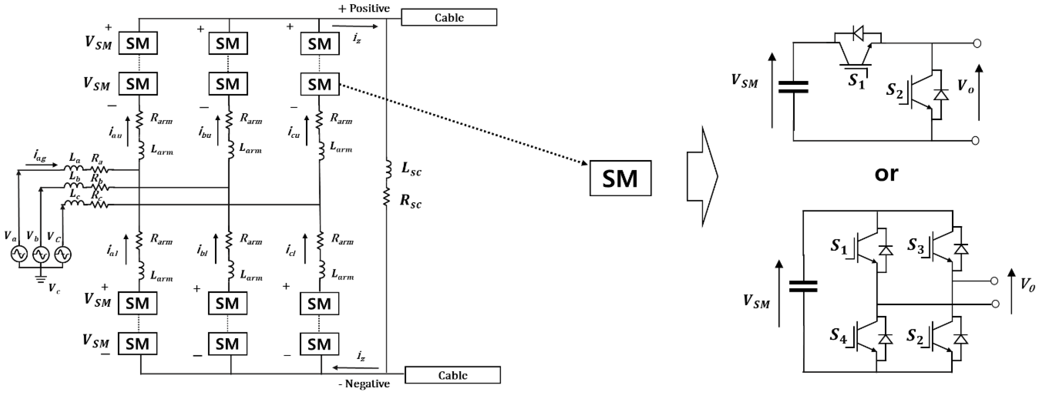
2. The Operation Characteristics of an MMC System

2.1. DC Fault Analysis of an MMC Before Blocking

The equivalent circuit representation of an MMC composed of an HB or FB configuration prior to the fault detection is shown in Figure 1. In this period, the DC fault current iz has not yet reached the fault detection limit. Considering KVL, the upper loop can be written as:
V x = L x d i x g d t + R i i x g + L a r m d i x u d t + R a r m i x u v x u + L s c d i x z d t + R s c i z + v n N
where x = a, b, c and Lsc and Rsc represent the equivalent values of the inductance and resistance of the transmission line.
The lower loop for each phase can be represented by:
V x = L x d i x g d t + R i i x g L a r m d i x l d t R a r m i x l v x l + v n N
Also applying KCL, in each node we obtain:
i x = i x u i x l
i z = i a l + i b l + i c l
i z = i a u + i b u + i c u
Subtracting Equation (2) from (1) yields:
L x d ( i x u + i x l ) d t + R z ( i x u + i x l ) + L s c d i z d t + R s c i z = ( v x u + v x l )  
Equation (6) is valid for all the phases. Adding Equation (6) for each phase, we obtain:
( 2 L z + 3 L s c ) d i z d t + ( 2 R z + 3 R s c ) i z = x = a , b , c ( v x u + v x l )  
For an MMC at any instant of time, N number of submodules are switched on, where N is the number of submodule (SM) per arm. Therefore, it can be written that:
( V x u + V x l ) = N V s m  
According to Reference [18], at this point in time all the capacitors are parallel and the DC current can be expressed as:
i z = 2 C s m N x = a , b , c ( v x u + v x l )  
where Csm is the capacitance of each individual SM. Substituting Equation (9) into Equation (7) will give:
( 2 L z + 3 L s c ) d 2 i z d t + ( 2 R z + 3 R s c ) d i z d t + N 2 C s m i z = 0  
Equation (10) provides the equation of the DC current iz. This equation will be valid until iz reaches the limit [19].

2.2. DC Fault Analysis of an MMC after Blocking
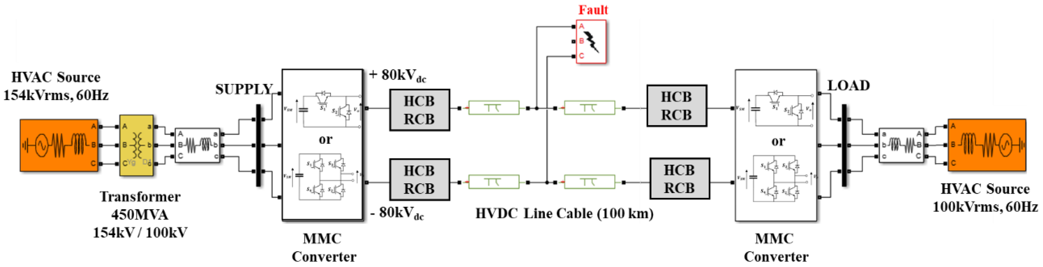
In an HB-MMC, as soon as a fault is detected, the IGBTs are blocked for their protection, but the anti-parallel freewheeling diodes still provide a path for the AC current to the DC line, thus feeding the fault. Therefore, DCCB is essentially required to block the fault current.
An FB-MMC system has the capability of suppressing the fault current. Initially, a current surge is allowed to flow through the IGBTs and feed the DC fault. However, as soon as the IGBTs are blocked, there is only one available current path through the series and reverse-connected DC capacitors of the submodules.
After the IGBTs are blocked, the fault current passes through the freewheeling diodes. In the process, the capacitors of FB submodules develop opposite polarity compared to the fault current during the DC fault. The complete blocking of the DC fault current takes place when the total voltage of each submodule capacitor becomes higher than the maximum peak line-to-line AC voltage, as shown in Equation (11). As a result, the fault current can be limited and a DC breaker with a low current rating can be used to isolate the faulty transmission line.
VAC,max < Varm,a + Varm,b,
where Varm,a and Varm,b represent the arm voltages which are stacked at each arm through the fault path.
The operation of FB- and HB-MMCs under DC side faults have been extensively covered in References [10,19,20].

3. Simulation Model

3.1. Test Bed Model

To compare the fault handling performance between HB- and FB-MMCs, a test bed was modeled in Matlab/Simulink, as shown in Figure 2. A bipolar point-to-point HVDC link was modeled using 40-level HB- and FB-MMCs. In the steady state, the MMC was operated with constant active and reactive power control. The reference voltage of the DC link was set at 80 kV, and the length of the transmission line was 100 km. The pole-to-pole fault was generated at 0.2 s.
Table 1 presents a summary of the HVDC system parameters. After the occurrence of the DC fault, the main controller trips the HB and FB converters within 500 microseconds to protect the converter. By performing this process, the DC fault contribution from the submodule capacitor can be prevented in HB-MMCs. The configuration of submodules in FB-MMCs does not allow the discharge of the DC side capacitor.

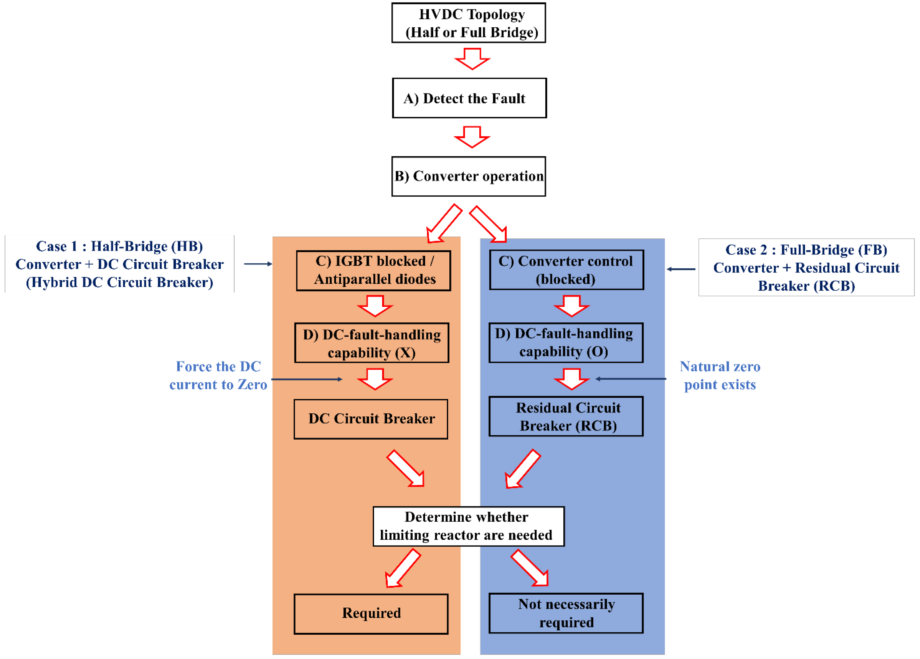
3.2. Comparison of System Operating Characteristics and Necessary Components by Case Types

The converter operation of HB- and FB-MMCs, after the fault detection, is shown in Figure 3. In the case of the HB-MMC, even if the IGBT is blocked, the converter continues to feed fault due to the presence of the freewheeling diode, so a DCCB is required to break the fault current. Due to the large fault current magnitude and its steep slope, a reactor is added in series with the DC line to limit the maximum stress on DCCB and assist its fault interruption operation. In the absence of a large reactor, DCCB is unable to perform fault interruption.
In the case of the FB-MMC, all IGBTs are blocked in the same way as the HB-MMC, but a reverse voltage is generated in the fault current path, so it is possible to cut off the current of the AC source by the converter itself. Therefore, when the natural zero point is generated through the converter blocking process, the DC fault is completely isolated through the RCB. Therefore, the FB-MMC system does not require a DCCB. As a result, a large limiting reactor is not necessarily required. The benefit of a limiting reactor, considering to its cost and size, is minimal. However, if the reactor is considered, the peak value of fault current will be reduced and time to reach the peak will increase. Due to its limited advantage, the limiting reactor can be left off in FB-MMC-based DC grids [21].
The operation characteristics of the two types of systems and the need for a current-limiting reactor are reflected in the simulation.

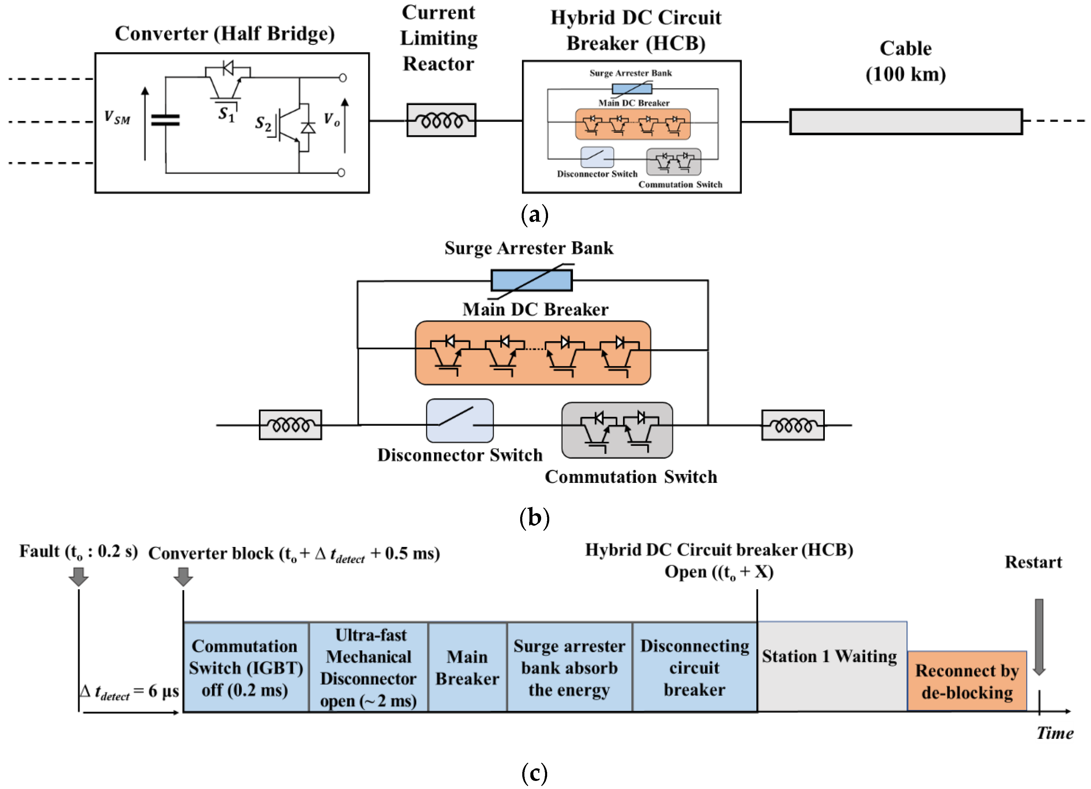
3.2.1. Case-1: Fault Management in an HB-MMC DC System Through DCCB

For HB-MMC systems, DCCBs are a necessary requirement for effectively clearing the DC faults, as shown in Figure 4a.
Unlike AC circuit breakers (ACCBs), HVDC circuit breakers (CBs) must create a current zero and dissipate the energy stored in the DC network. Recently, industry and academia have extensively researched DCCBs to overcome various well-known limitations. Among the developed prototypes, HCBs, which can block a 9-kA fault current within 5 ms, are attracting attention as the most suitable circuit breakers for application in HVDC systems [22,23].
In this paper, we proposed an HCB due to its excellent interruption capability (large di/dt with large dv/dt) and small interruption times (<5 ms). In addition, a large current-limiting reactor was installed at the DC terminal of the MMC to assist the operation of the HCB.
Figure 4b presents the structure of the HCB mentioned above. The HCB contains a load commutation switch (LCS), an ultrafast mechanical disconnector (UFMD), and a main breaker (MB). As shown in the operation characteristics of Figure 4c, the detection time of the fault current is assumed to be 6 µs. The converter is blocked within 0.5 ms after the detection of a fault. During the normal operation of the HCB, the load current flows through a nominal path that comprises of LCS and UFMD. When a DC fault is detected, the LCS opens immediately and the current is commutated to the MB. Then the UFMD opens within 2 ms and isolates the LCS from the faulted line. With the UFMD in an open position, the commutation path interrupts the fault current, and energy of the fault is absorbed by the arrestor bank. In this process, the DC current decreases quickly and can be cleared within a few milliseconds.

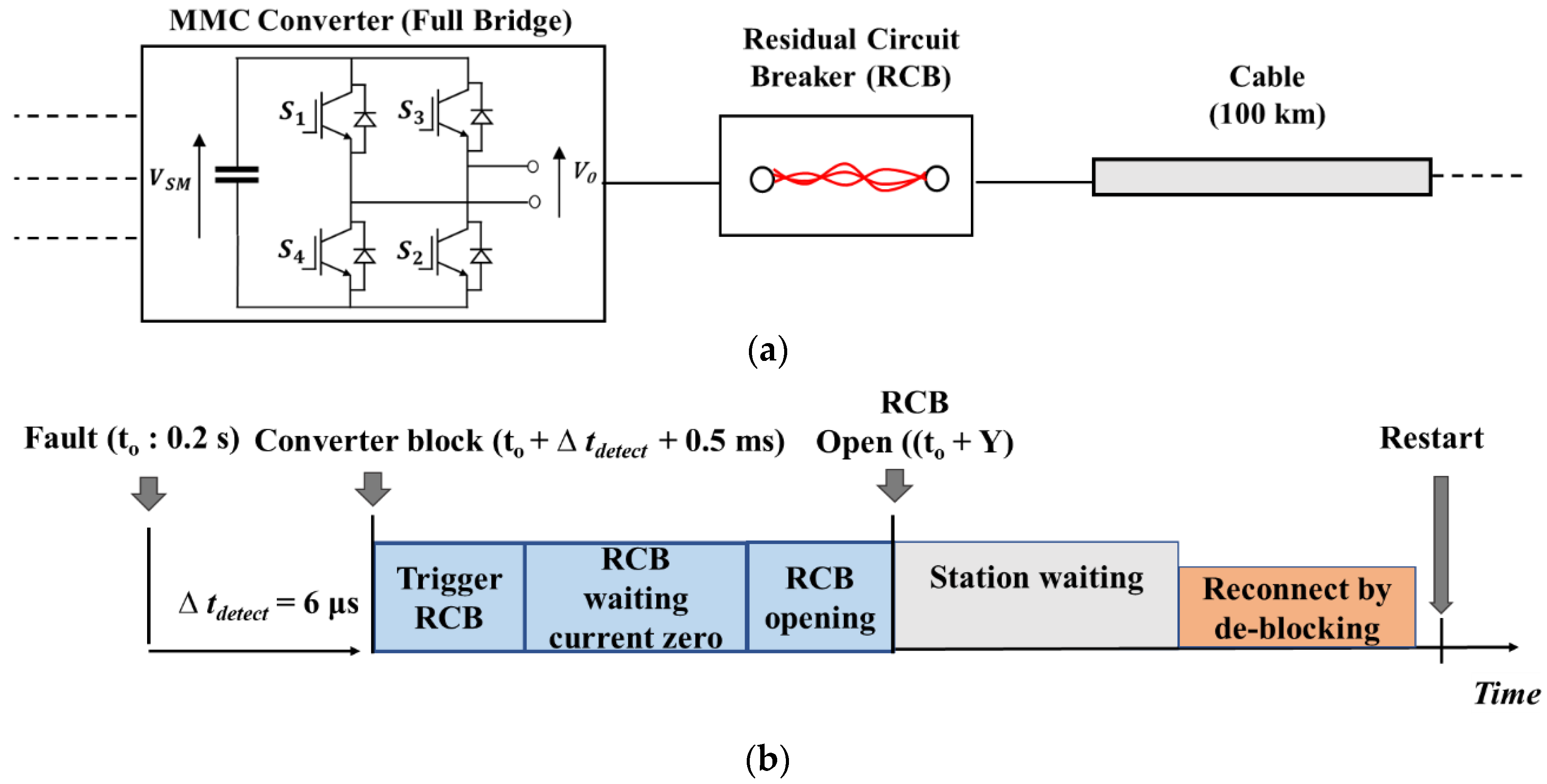
3.2.2. Case-2: Fault Management in an FB-MMC Using RCB

FB-MMCs are a superior alternative to HB-MMCs in terms of fault handling capability. As shown in Figure 5a, the rapid reverse of the DC voltage control of an FB-MMC can be typically provided within a few milliseconds; therefore, DCCB are not necessarily needed for protection.
When the fault is detected, all IGBTs of the SMs are blocked, and the capacitors generate a reverse voltage to block the AC side currents. Since the converter has already interrupted the fault current, an RCB is sufficient to isolate the fault.
Also, unlike Case-1, the FB-MMC system does not require a DCCB. Figure 5b shows the fault handling mechanism in the FB-MMC system: detecting the fault, blocking the converter, and triggering the RCB to generate the natural current zero. Finally, if a reconnection is established by deblocking the converter and reclosing the RCB, system can be restored to the normal state.

4. Interruption Performance of HB- vs FB-MMC DC Grids

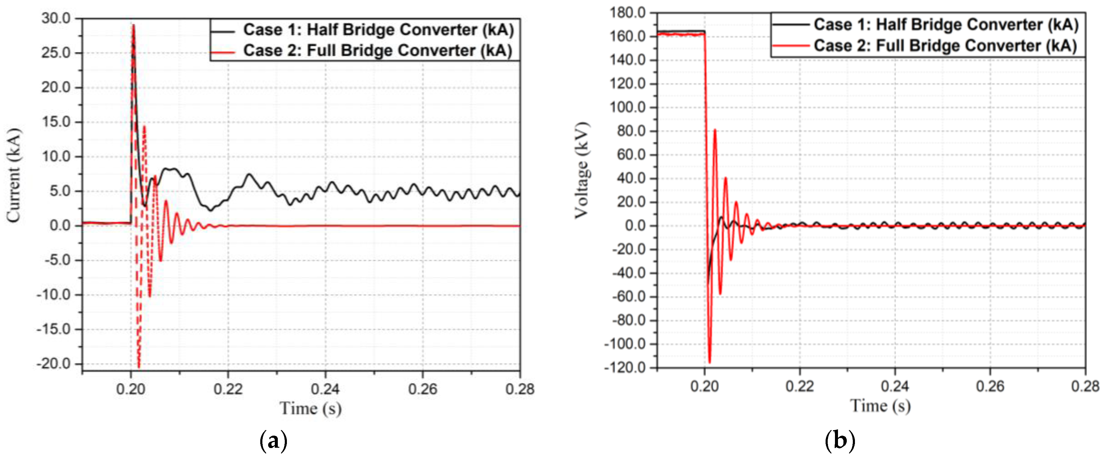
4.1. Comparison of Fault Current Blocking Performance (Pole-to-Pole Fault)

Prior to the analysis of fault handling performance with protection devices, it is important to analyze the fault current blocking ability of the two types of MMCs. We simulated a pole-to-pole fault at 0.2 s on the DC side of the rectifier to consider the worst-case fault.
Figure 6a shows that the peak current magnitude is about 30 kA for both topologies. In the case of the HB-MMC system, a fault current of about 5 kA is sustained due to the presence of freewheeling diodes.
However, in the case of the FB-MMC system, all IGBTs are blocked when a fault is detected, and a reverse voltage is generated, which forces the fault current to zero.
The DC side voltage during fault transient is shown in Figure 6b. In the case of the HB-MMC system, the voltage in the transient state suddenly reverses the polarity, and then approaches zero in about 20 ms. However, in the case of the FB-MMC system, the voltage oscillations are sustained on the DC side for about 15 ms.

4.2. Comparison of Fault Current Blocking Performance (Pole-to-Ground Fault)

In this section, we simulated a pole-to-ground fault at 0.2 s on the DC side of the rectifier to consider the worst-case fault. Figure 7a shows that the peak current magnitude is about 23.5 kA for both topologies. In the case of the HB-MMC system, the fault current of about 11.5 kA is sustained due to the presence of freewheeling diodes. However, in the case of the FB-MMC system, all IGBTs are blocked when a fault is detected, a reverse voltage is generated to block the fault current, and the fault current naturally approaches zero. The DC side voltage during the fault transient state is shown in Figure 7b. In both systems, voltage oscillations are sustained on the DC side.

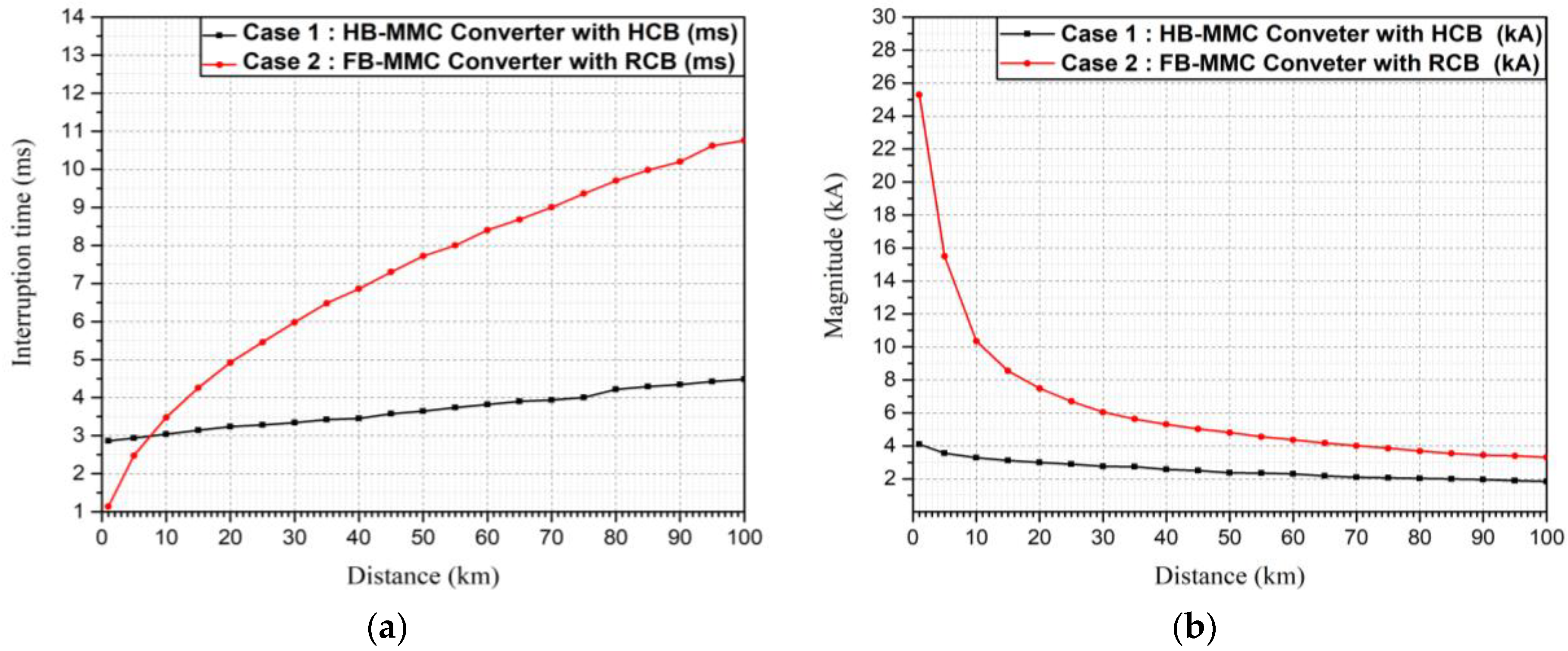
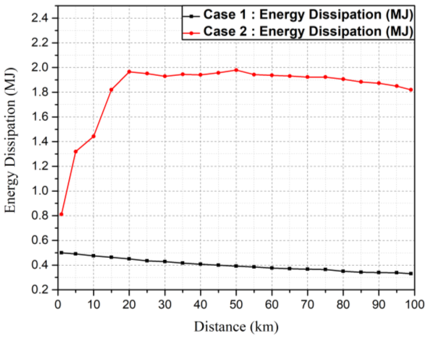
4.3. Comparison of Fault Interruption Performance

In this section, we compared the interruption performance of Case-1 and Case-2 according to the location of the occurrence of fault on the DC line. The peak magnitude of the fault current and interruption time are considered key parameters for evaluating the performance of the two cases.
For a pole-to-pole fault at 5 km from the rectifier, the peak magnitude of the fault current in Case-2 is 15.5 kA; it is only 3.5 kA in Case-1, as shown in Figure 8. The lower peak fault current magnitude in Case-1 is due to the presence of the current-limiting reactor and the fast-operating HCB.
The total interruption time as well as the peak fault current magnitude in the two cases is compared in Figure 9.
It can be seen in Figure 9a that the interruption time in Case-1 does not change considerably with the variation in fault location. However, in Case-2 the interruption time increases considerably for faults farther away from the rectifier. The quick interruption in Case-1 can be attributed to the presence of the fast-acting HCB. However, the inherent blocking characteristics of the FB-MMC in Case-2 are dependent on the natural elimination of the fault current. Therefore, if the fault location moves away from the rectifier, the interruption time increases due to the increase in inductive and capacitive components of the transmission line. It can be seen in Figure 9a that for faults occurring beyond 8 km, Case-1 offers a smaller interruption time.
Figure 9b shows that in both cases the peak magnitude of the fault current decreases upon increasing the distance of the fault from the rectifier. However, due to presence of an HCB in Case-1, the fault is interrupted before its natural peak and therefore the peak magnitude is quite low regardless of the fault location. However, in Case-2 the peak magnitude of the fault current is dependent on the inductive reactance of the line. Therefore, the peak magnitude is quite high for faults occurring on the converter terminal.
In conclusion, we found that Case-1 has a lower fault current magnitude and lower interruption time for most fault locations.
Figure 10 shows the comparison of the energy dissipation of the circuit breaker according to the fault location.
In Case-1, the circuit breaker must fully cope with the DC fault current, which has high di/dt. Therefore, we confirmed that the energy dissipation in the HCB is more than 0.32 MJ, even if the fault location is far away from the converter side.
In Case-2, the peak fault current is higher than that in Case-1 and the interruption time is also larger. Therefore, the energy dissipation in the RCB was found to be about 2 MJ when the fault occurs at 20 km.

5. Transient Performance of the System in DC Faults

The occurrence of DC faults and their clearance introduce current and voltage transients on both the AC and DC sides of the power system. These transient events affect the power quality and can potentially deteriorate the power system components. In this section, an analysis of the transient response of the power system in two cases is presented.

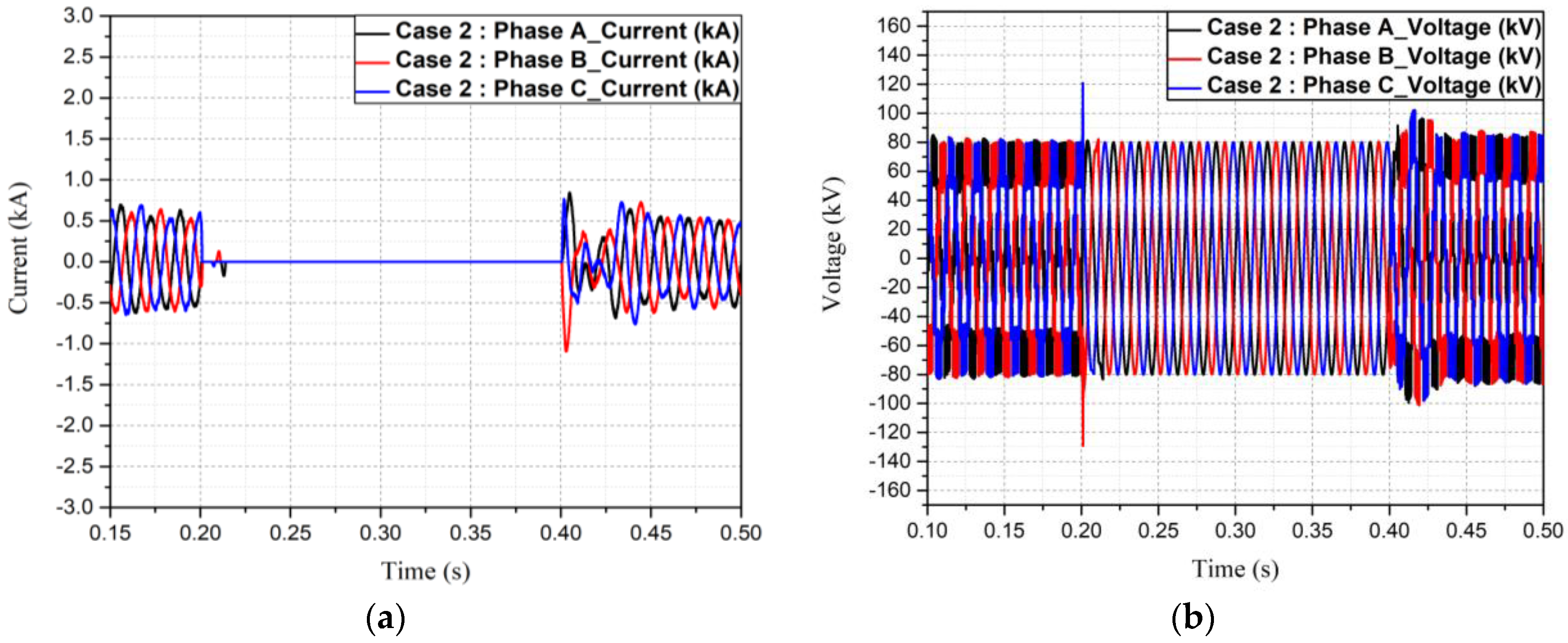
5.1. Analysis of the Current and Voltage Transient of the AC and DC Sides Considering a Reclosing Operation

Since, most transmission line faults are temporary, a reclosing operation is considered for a complete analysis of fault transients. The power system transients were analyzed to determine the suitable grid topology for the two cases.
The pole-to-pole fault was simulated at 0.2 s at a distance of 5 km from the rectifier, and the converter was set to operate within 500 µs after the detection of a fault. The circuit breaker attempts to clear the fault immediately after converter blocking. A delay of 0.2 s is introduced to allow for the deionization of fault location, following which the de-blocking of the converter and reclosing of the circuit breaker are initiated.

5.1.1. Transient Current and Voltage of the AC System

Figure 11 shows the AC side current and voltage waveforms for Case-1. Figure 11a presents the AC side current graph. It shows that the peak current approaches 2 kA just after 0.2 s, i.e., before fault interruption. After 0.4 s, i.e., during reclosing, the AC current exceeds its steady-state value before reaching the steady state in 50 ms. A voltage transient with a peak of up to 90 kV can be observed during the reclosing operation, as shown in Figure 11b.
Figure 12 shows the AC-side current and voltage waveforms for Case-2 during interruption and reclosing operations. It can be seen in Figure 12a that there is no current overshoot during fault inception due to the instant blocking of IGBTs. During reclosing, the maximum current does not exceed −1.02 kA, which is 0.4 kA higher than that of Case-1.
Figure 12b shows that an overvoltage of 120 kV occurs during the converter blocking at the time of fault. An overvoltage of up to 100 kV occurs during the reclosing process, followed by a return to the steady state in 10 s.
As a result, although the magnitude of the current and the voltage are not much different on the AC side, the current magnitude in the reclosing and the overvoltage magnitude in the interruption process are relatively high, and the time to achieve the steady-state voltage after the reclosing process is very long. Therefore, Case-1 would have advantages in terms of the stability of the AC system and lower stress on the insulation.

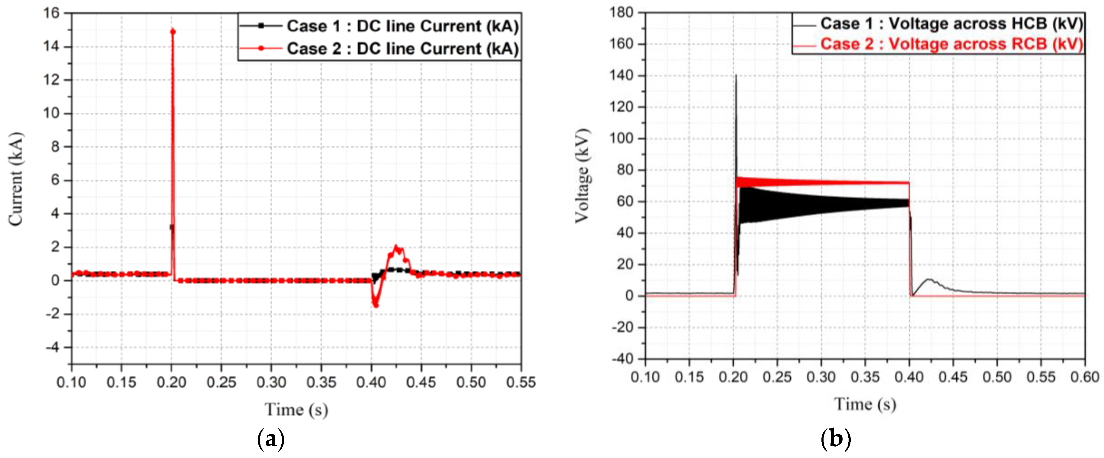
5.1.2. The Analysis of the DC Current and Voltage Waveform Across the HCB and RCB in the Transient State

Figure 13 is a graph showing the DC current flowing through the circuit breaker and the voltage across the circuit breaker during the fault and reclosing process. As shown in Figure 13a, in Case-1, the maximum fault current is limited to 3.3 kA due to the quick HCB operation.
In Case-2, however, due to the fault handling capability of the FB-MMC, it is confirmed that the fault current rapidly increases to about 15.5 kA and then rapidly decreases.
In the reclosing operation, Case-1 has a maximum fault current magnitude of 0.8 kA, and it is confirmed that it achieves a steady state in 100 ms. Case-2 showed high di/dt as well as the peak magnitude, which is about 2 kA—more than twice the value of that in Case-1.
Considering the insulation design of the system and device, Case-2 with a high current magnitude and high di/dt slope would be detrimental to the power system components.
The voltage waveform across the circuit breaker is presented in Figure 13b. In Case-1 and Case 2, the voltage across the circuit breaker increased suddenly after 0.2 s. In the reclosing process, the recovery voltage across the HCB decreases within 50 ms.

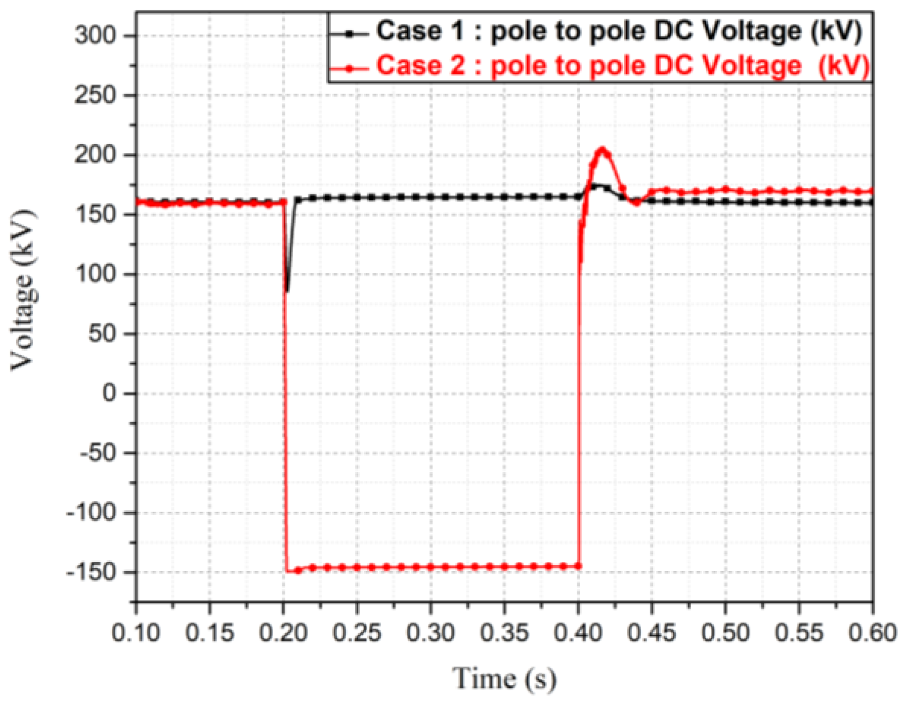
5.1.3. The Transient Overvoltage Analysis During DC Faults

This section compares the overvoltage characteristics across the DC line as a result of DC faults in two cases.
The voltage across the converter in a pole-to-pole fault is presented in Figure 14. In Case-1, the voltage dip is not large due to the presence of voltage across the circuit breaker during the fault. In addition, it was confirmed that the voltage in the normal state recovered to 160 kV within 100 ms after the peak overvoltage of 175 kV occurred during the reclosing operation.
On the other hand, in Case-2, a reverse voltage was applied across the DC system due to the blocking operation of the FB-MMC to prevent the AC system from feeding in to the DC fault. In the case of reclosing, an overvoltage of 205 kV was obtained. In addition, the recovery time to a DC-rated voltage of 160 kV after reclosing was much longer than that of Case-1, and it was confirmed that the steady-state voltage was reached within 10 s, compared to 100 ms in Case-1.
Figure 15a shows the overvoltage graph of Case-1, showing the maximum overvoltage of 90 kV during the reclosing process. However, in Case-2, a maximum overvoltage of 150 kV and a longer time to reach the steady state was observed, as shown in Figure 15b.
System components are expected to carry larger currents as well as bear higher overvoltage stress during fault transience in Case-2.

5.2. The Preferable Case for HVDC Grid Application

In this section, we evaluated the feasibility of applying two fault handling solutions to HVDC grids based on the simulation results. The summary of our analysis is presented in Table 2.
Although in Case-1 the HCB alone copes with a large DC fault current, the power system experienced lower overvoltage stress. However, considering the high energy dissipation in the HCB, a sophisticated insulation design is required.
Table 2 shows that in Case-1, the fault current, overvoltage magnitude, and interruption time are low. Conversely, in Case-2, the abovementioned parameters are relatively high. Therefore, additional consideration for the insulation design is required to ensure the reliable long-term operation of the DC grid. Furthermore, the oscillating voltage in the transient state is expected to stress the overall system components. As a result, we conclude that Case-1 would be a better solution for HVDC grid application.

6. Conclusions

Two types of representative MMC systems along with an HCB or RCB have been investigated for the feasibility of application in an HVDC grid. The comparative studies have been conducted in terms of maximum fault current, total interruption time, and voltage characteristics of the grid during the transient period.
Although the HB-MMC with a DC circuit breaker has a disadvantage of stress on the HCB associated with the insulation design of the CB itself, it appears to be the likely candidate for application in future DC grids due to its low fault current, low interruption time, low overvoltage magnitude, and faster recovery. Furthermore, it is beneficial in terms of insulation design because it applies relatively low voltage stress to various power system components during the transient period.

Author Contributions

H.-Y.L. conceptualized the topic, formulated methodology, performed simulations, and prepared an original draft; M.A. performed a formal analysis and reviewed the draft; K.-H.P. curated the data and edited the draft; B.-W.L. supervised the study.

Funding

This research received no external funding.

Acknowledgments

This work was supported by the Ministry of Trade, Industry, and Energy of Korea through the Human Resources Program in Energy Technology of the Korea Institute of Energy Technology Evaluation and Planning (KETEP) under Grant 20174030201780 and by the KEPCO Research Institute under the project entitled by “Design of analysis model and optimal voltage for MVDC distribution system (R17DA10)”.

Conflicts of Interest

The authors declare no conflict of interest.

References

  1. Shabestari, P.M.; Ziaeinejad, S.; Mehrizi-Sani, A. Reachability analysis for a grid-connected voltage-sourced converter (VSC). In Proceedings of the 2018 IEEE Applied Power Conference and Exposition (APEC), San Antonio, TX, USA, 4 March 2015; pp. 2349–2354. [Google Scholar]
  2. Yazdani, A.; Iravani, R. Voltage-Sourced Converters in Power Systems: Modeling, Control, and Applications; Wiley-IEEE Press: Hoboken, NJ, USA, 2010; pp. 115–125. ISBN 978-0-470-52156-4. [Google Scholar]
  3. Shewarega, F. Simplified modeling of VSC-HVDC in power system stability studies. IFAC Proc. Vol. 2014, 47, 9099–9104. [Google Scholar] [CrossRef]
  4. Frank, C.M. HVDC circuit breakers: A review identifying future research needs. IEEE Trans. Power Deliv. 2011, 26, 998–1007. [Google Scholar] [CrossRef]
  5. Mokhberdoran, A.; Carvalho, A. A review on HVDC circuit breakers. In Proceedings of the 3rd Renewable Power Generation Conference (RPG 2014), Naples, Italy, 24–25 September 2014. [Google Scholar]
  6. Rodriguez, J. Multilevel converters: An enabling technology for high-power applications. Proc. IEEE 2009, 97, 1791–1792. [Google Scholar] [CrossRef]
  7. He, Z.; Hu, J. Mechanical DC circuit breaker and FBSM-based mmc in a high-voltage MTDC networks: Coordinated operation for network riding through dc fault. In Proceedings of the Renewable Power Generation (RPG 2015), Beijing, China, 17–18 October 2015; pp. 1–6. [Google Scholar]
  8. Chen, X.; Zhao, C. Research on the fault characteristics of HVDC based on modular multilevel converter. In Proceedings of the 2011 IEEE Electrical Power and Energy Conference, Winnipeg, MB, Canada, 3–5 October 2011. [Google Scholar]
  9. Jonsson, T.; Lundberg, S. Converter Technologies and Functional Requirements for Reliable and Economical HVDC Grid Design. In Proceedings of the 2013 CIGRE Canada Conference, Calgary, AB, Canada, 9–11 September 2013. [Google Scholar]
  10. Najmi, V. Modelling, Control and Design Considerations for Modular Multilevel Converters. Master’s Thesis, Electrical Engineering Department, Virginia Polytechnic Institute and State University, Blacksburg, VA, USA, May 2015. [Google Scholar]
  11. Henry, S.; Denis, A.M. Feasibility study of off-shore HVDC grids. In Proceedings of the IEEE PES General Meeting, Providence, RI, USA, 25–29 July 2010. [Google Scholar]
  12. Bucher, M.K.; Walter, M.M. Options for ground fault clearance in HVDC offshore networks. In Proceedings of the 2012 Energy Conversion Congress and Exposition (ECCE), Raleigh, NC, USA, 15–20 September 2012. [Google Scholar]
  13. Petino, C.; Heidemann, M. Application of multilevel full bridge converters in HVDC multiterminal systems. IET Power Electron. 2016, 9, 297–304. [Google Scholar] [CrossRef]
  14. Xu, Z.; Xiao, H. DC Fault Analysis of Clearance Solutions of MMC-HVDC systems. Energies 2018, 11, 941. [Google Scholar] [CrossRef]
  15. Zhang, Z. Short-Circuit Current Calculation and performance requirement of HVDC Breakers for MMC-MTDC Systems. IEEJ Trans. Electr. Electron. Eng. 2016, 11, 168–177. [Google Scholar] [CrossRef]
  16. Khan, U.A.; Lee, B.W. Feasibility analysis of a novel hybrid-type superconducting circuit breaker in multiterminal HVDC networks. Phys. C Supercond. Appl. 2015, 518, 154–158. [Google Scholar] [CrossRef]
  17. Think Grid. Available online: http://www.think-grid.org/fault-blocking-converters-dc-networks-1 (accessed on 20 July 2018).
  18. Win, J.; Saeedifard, M. Hybrid design of modular multilevel converters for HVDC systems based on various submodule circuits. IEEE Trans. Power Deliv. 2015, 30, 385–394. [Google Scholar]
  19. Nami, A.; Liang, J. Analysis of Modular Multilevel Converters with DC Short Circuit Fault Blocking Capability in Bipolar HVDC Transmission Systems. In Proceedings of the 2015 17th European Conference on Power Electronics and Applications (EPE’15 ECCE-Europe), Geneva, Switzerland, 8 September 2015; pp. 1–10. [Google Scholar]
  20. Fazel, S.S. Investigation and Comparison of Multi-Level Converters for Medium Voltage Applications. Ph.D. Thesis, Berlin University, Berlin, Germany, July 2015. [Google Scholar]
  21. Kontos, E.; Pinto, R.T. Impact of HVDC transmission system topology on multiterminal DC network faults. IEEE Trans. Power. Deliv. 2013, 30, 844–852. [Google Scholar] [CrossRef]
  22. Tahata, K. HVDC circuit breakers for HVDC grid applications. In Proceedings of the 11th IET International Conference on AC and DC Power Transmission, Birmingham, UK, 10–12 February 2015. [Google Scholar]
  23. Hafner, J.; Jacobson, B. Proactive hybrid HVDC breakers—A key innovation for reliable HVDC grids. In Proceedings of the CIGRE International Conference, Bologna, Italy, 13–15 September 2011. [Google Scholar]
Figure 1. Equivalent circuit of a modular multilevel converter (MMC) system composed of a half bridge (HB) or full bridge (FB) configuration.
Applsci 08 01834 g001
Figure 2. Test bed model in Matlab/Simulink. Converters are composed of 40-level HB- and FB-MMCs. The pole-to-pole DC fault is introduced at a variable distance from the rectifier.
Applsci 08 01834 g002
Figure 3. Comparison of overall operating characteristics and the need for a current-limiting reactor.
Applsci 08 01834 g003
Figure 4. Case-1: DC fault handling solution for an HB-MMC based on a hybrid circuit breaker (HCB): (a) configuration of Case-1; (b) structure of the HCB; (c) fault handling under a DC short-circuit fault.
Applsci 08 01834 g004
Figure 5. Case-2: DC fault handling solution composed of an FB-MMC with a residual circuit breaker (RCB): (a) configuration of Case-2; (b) operation process for DC fault handling under a DC short-circuit fault.
Applsci 08 01834 g005
Figure 6. Simulation of a DC pole-to-pole fault with MMCs: (a) current waveform in the transient state; (b) voltage waveform in the transient state.
Applsci 08 01834 g006
Figure 7. Simulation of a DC pole-to-ground fault with MMCs: (a) current waveform in the transient state; (b) voltage measured at converter terminals.
Applsci 08 01834 g007
Figure 8. Fault handling interruption performances: (a) fault current interruption characteristic of Case-1 with an HCB; (b) fault current interruption characteristic of Case-2 with an RCB.
Applsci 08 01834 g008
Figure 9. Comparison analysis of interruption characteristics according to the location of the fault on the DC line: (a) interruption time; (b) maximum fault current magnitude.
Applsci 08 01834 g009
Figure 10. Comparison of energy dissipation on the circuit breaker (CB). Case-1 is an HCB; Case-2 is an RCB.
Applsci 08 01834 g010
Figure 11. The transient waveforms of the AC system in Case-1: (a) current waveform; (b) voltage waveform.
Applsci 08 01834 g011
Figure 12. The current and voltage waveform at the AC side of Case-2 in interruption and reclosing operations: (a) current waveform; (b) voltage waveform.
Applsci 08 01834 g012
Figure 13. The waveform of the DC line current and voltage across the CB in the transient state: (a) the DC line current; (b) the voltage across the CB.
Applsci 08 01834 g013
Figure 14. The waveform of pole-to-pole DC voltage in the case of pole-to-pole fault.
Applsci 08 01834 g014
Figure 15. The waveform of pole-to-ground DC voltage in the fault and reclosing process: (a) Case-1; (b) Case-2.
Applsci 08 01834 g015
Table 1. Summary of high-voltage direct-voltage (HVDC) system parameters.
ParametersSpecifications
Voltage source converter (VSC) HVDC typeBipolar HB-/FB-MMC
AC source voltage (rectifier side) 154 kV
Number of submodules per arm40
Equivalent capacitance10 uF
Current-limiting reactor20 mH
Transformer power rating450 MVA
Transformer voltage ratio154 kV/100 kV
DC cable resistance0.0133 Ω/km
DC cable inductance0.8273 mH/km
DC cable capacitance0.0139 uF/km
Length of transmission line100 km
Table 2. Comparison of the two fault-handling solutions.
ParameterSimulation ConditionCase-1Case-2
Structure-HB-MMC + HCBFB-MMC + RCB
DC-fault-handling capabilityOO
Current-limiting reactorRequiredNot necessarily required
Total interruption time (ms)Variable fault location 3~4.5 (ms)~11 (ms)
Maximum DC fault current in fault period (kA)2~4 (kA)3~25 (kA)
Energy dissipation across circuit breaker (MJ)0.32~0.51 (MJ)0.01~0.05 (MJ)
Maximum AC current in fault period (kA)5 km from the sending end converter side2 (kA)0.15 (kA)
Maximum AC current in reclosing period (kA)0.62 (kA)1.02 (kA)
Maximum DC current in reclosing period (kA)5 km from the sending end converter side (pole-to-pole)0.8 (kA)2 (kA)
Maximum DC system overvoltage (kV)175 (kV)205 (kV)
Time to recovery (ms)~0.1 (s)10 (s)
Maximum DC overvoltage in reclosing period (kV)5 km from the sending end converter side (pole-to-ground)91 (kV)152 (kV)
Stress on insulation-Relatively lowRelatively high
Feasibility in HVDC grid application-★★★★★★★☆☆☆
* Excellent ★★★★★, Very Good ★★★★☆, Good ★★★☆☆, Fair ★★☆☆☆, Poor ★☆☆☆☆

