Numerical Investigation of Energy Saving Characteristic in Building Roof Coupled with PCM Using Lattice Boltzmann Method with Economic Analysis


1
School of Management, Xi’an University of Architecture and Technology, Xi’an 710055, Shaanxi, China
2
Key Laboratory of Thermo-Fluid Science and Engineering of MOE, School of Energy and Power Engineering, Xi’an Jiaotong University, Xi’an 710049, Shaanxi, China
*
Author to whom correspondence should be addressed.
Appl. Sci. 2018, 8(10), 1739; https://doi.org/10.3390/app8101739
Submission received: 10 September 2018
/
Revised: 20 September 2018
/
Accepted: 25 September 2018
/
Published: 26 September 2018
(This article belongs to the Special Issue Clean Energy and Fuel (Hydrogen) Storage)
Abstract
:Featured Application
The current work has potential applications in economically designing green buildings in the summer hot and winter cold region of China.
Abstract
Due to their characteristics of high energy storage density and a nearly constant melting temperature, phase change materials (PCMs) could be inserted into the roof of green buildings in order to reduce the energy consumption and ameliorate the room thermal comfort. In this paper, an enthalpy based multiple-relaxation-time (MRT) lattice Boltzmann method (LBM) was developed to calculate the transient phase change conjugate heat transfer with solar radiation inside the green building’s PCM roof in the hot summer and cold winter areas of China. The effect of the PCM melting temperature on the variation of the roof internal temperature was investigated and the energy saving characteristic of the PCM roof under an intermittent energy utilization condition was also analyzed by comparing with the performance of the roof filled with sensible insulating materials (SIMs). Then, the life cycle incremental costs and incremental benefits of a PCM roof and SIM roof were studied by using the comprehensive incremental benefit model so that the green building roof could be economically evaluated. The results indicate that a temperature rise inside the roof during summer cooling time could be delayed due to the latent heat of the PCMs. It was also found that the melting temperature and the thickness of the PCM layer should be chosen appropriately for enhancing the energy saving amount of a PCM roof. Based on this, the PCM roof could have a better energy saving capability than the SIM roof. During the winter heating time, as the environment temperature and the room temperature are both below the PCM melting temperature, the PCM roof does not have a latent heat characteristic so that it performs like a SIM roof. Furthermore, due to the high price of PCMs, the incremental cost of green building is increased, which makes the PCM roof have a negative comprehensive incremental benefit. Under this circumstance, developing PCMs with a low price and stable chemical properties is a key scientific bottleneck for a wider application of PCM roofs in the architecture engineering field.
1. Introduction
Energy and environment are the two of the most significant basic factors for the development of the human society. The combustion of fossil fuels, which emit a great deal of carbon dioxide contributes to the global warming issue and effective energy saving techniques are essential for solving the energy crisis and environmental issues [1]. Building energy consumption was responsible for more than 40% of the total energy cost in China during the past seven years [2,3]. Furthermore, the energy consumption of a building is still increasing as people’s living standards improve. For this reason, developing green buildings with high energy saving characteristics has been an indispensable task for local government in order to protect the living environment and realize sustainable development. Reducing the energy release through the building envelope is an important approach for decreasing the buildings energy consumption. Due to their low thermal conductivities and latent heat characteristics, the PCMs could be inserted into the building envelope as a thermal insulation layer to decrease the building energy cost, which has attracted a lot of research attention during recent years [4,5,6]. As the PCMs absorb and release heat during a solid-liquid phase change process at a nearly constant temperature, it could not only increase the thermal resistance of a building’s envelope but also attenuate the temperature oscillation so that the thermal comfort of the building’s rooms is improved.
The research methodologies for building a PCM envelope can be generally categorized as follows: Theoretical method, experimental method, and numerical method. With the fast progress of computer science and numerical modelling schemes, numerical methods have been widely used to analyze the energy saving characteristics of buildings [7]. Barrientos applied a one-dimensional finite difference method to investigate the transient conjugate heat transfer inside the building walls contained with PCMs [8]. It was found that the integration of a PCM layer into a building wall could diminish the instantaneous heat flux magnitude through the wall when the PCM melting temperature was appropriately chosen. Besides, due to the elevated solar radiation, the wall orientation has a more obvious effect on the energy consumption of a building during the summertime. Zwanzig solved the one-dimensional transient heat equation in the multilayered wallboard using the Crank-Nicolson discretization scheme [9]. It was found that an optimum location for PCM placement existed in terms of different thermal resistances between the PCM layers and the external thermal boundary conditions. Jin numerically optimized the location of the PCM layer under different parametric conditions by validating their model with experiments conducted using a dynamic wall insulator [10]. They presented that the optimum PCM layer location approaches the exterior surface of the wall when the melting temperature and the latent heat of PCMs were increased. By validating the numerical model with a PCM wallboard heat storage experiment, Xie investigated the thermal performance of PCM wallboards for practical engineering [11]. Their results indicated that the PCM wallboard performance could be adverse in different seasons and the thermal analysis through an entire year is also necessary. The above research was mainly related to the heat transfer properties of PCM walls. However, the thermal loss of roofs contributes almost 70% of the total heat loss in building envelopes due to direct solar radiation and heat transfer between the roof and the exterior environment. Under this situation, the thermal performance of roofs imbedded with PCM layers deserves more scientific investigations. Li numerically analyzed the thermal performance of a roof that contained PCM in a single residential building with respect to the factors of solar radiation intensity, roof slope, PCM melting temperature and layer thickness [3]. They concluded that the roof slope has a more significant influence on the thermal performance of a PCM roof compared to the melting temperature and latent heat of PCM in the region of northeast China. Tokuc developed a one-dimensional model based on the first law of thermodynamics to carry out the time-dependent simulation of a PCM roof in Istanbul under summer conditions [12]. The results demonstrated that a PCM thickness of 2 cm is suitable for use in flat roofs in this specific area and their experimental and numerical results were consistent. Liu analyzed the thermal performance of a PCM-filled double glazing roof using a numerical method [13]. It was indicated that the semi-transparent property and zenith angle had a big effect on the thermal performance. In addition, the temperature lag time of a PCM roof increases with the increment of the PCM layer thickness. Although a lot of research related to PCM inserted into a building envelope exists, little work has been carried out for the hot summer and cold winter region in China where the climate conditions are quite different from other areas. In China’s hot summer and cold winter region, an air conditioner is indispensable for both the summer cooling season and the winter heating season, which consumes a huge amount of electricity. Based on this, the current paper aims to investigate the conjugate phase change heat transfer and the energy saving benefit in the PCM roof of the hot summer and cold winter region in China.
During the past two decades, the lattice Boltzmann method (LBM) has been developed as a powerful numerical method for solving complicated heat transfer problems [14,15]. For the solid-liquid phase change phenomenon, the existing LBM schemes could be classified into three categories: (1) The phase-field method [16,17]; (2) the immersed boundary method [18]; (3) the enthalpy-based method [19,20,21,22,23,24]. Due to its simplicity and numerical robustness, the enthalpy-based method is the most widely used scheme for simulating solidification and melting problems in scientific and engineering fields. Jiaung firstly investigated the solid-liquid phase change problem using an enthalpy-based lattice Boltzmann method [19]. However, the iteration of latent heat source term is required in their scheme, which increases the computational load. Eshraghi developed an implicit LBM scheme for conduction with a solid-liquid phase change [20]. By solving a linear system of equations, the numerical iteration process for the latent heat source term could be avoided. To further improve the computational efficiency, Huang modified the equilibrium function for temperature for which the circumstances for the iteration of the latent heat source or solving a linear system of equations are not indispensable [21]. In order to ameliorate the numerical stability and reduce the numerical diffusion during the phase change, Huang further developed the multiple-relaxation-time (MRT) LBM for a solid-liquid phase change using enthalpy formulation [22]. Besides, by decoupling the thermal conductivity and the specific heat from the relaxation time and the equilibrium distribution function, this model is demonstrated to be appropriate for modelling the conjugate heat transfer. Recently, Li also developed MRT LBM models for axisymmetric and three-dimensional solid-liquid phase change problems [23,24]. On the other hand, due to its highly parallel nature, the lattice Boltzmann method has been successfully installed into graphics processor units (GPU) to achieve parallel computing for several different heat transfer and fluid flow applications [25,26,27,28,29,30].
In this paper, the MRT enthalpy-based LBM with GPU acceleration was used to investigate the conjugate phase change heat transfer of a PCM roof in the hot summer and cold winter region of China. Then, by obtaining the energy loss through the roof during the summer cooling time and the winter heating time, the comprehensive incremental model was applied to evaluate the economic benefit of the PCM roof building during its life cycle. The remainder of the paper is organized as follows. In Section 2, the mathematical model for conjugate heat transfer with phase change and its thermal boundary conditions is presented. In Section 3, the details of the enthalpy-based MRT lattice Boltzmann method and the comprehensive incremental benefit model are shown. The results and discussion are presented in Section 4. A conclusion is finally drawn in Section 5.
2. Mathematical Model for Conjugate Heat Transfer with Phase Change
According to the configuration standard of a building envelope in the hot summer and cold winter region of China, the current research focuses on the heat transfer capability and energy saving characteristics of the following three different roofs: (1) Ordinary roof, its configuration from the top to the bottom is: A 20 mm thick cement layer, a 100 mm thick reinforced concrete layer, and a 20 mm thick lime layer; (2) a PCM roof, its configuration from the top to the bottom is: A 20 mm thick cement layer, a 100 mm thick reinforced concrete layer, a 30 mm thick phase change material (PCM) layer, and a 20 mm thick lime layer; (3) a SIM roof, its configuration from the top to the bottom is: A 20 mm thick cement layer, a 100 mm thick reinforced concrete layer, a 30 mm thick sensible insulating material (SIM) layer, and a 20 mm thick lime layer. In order to simplify the mathematical complication, the following reasonable assumptions are made for the current modelling: (1) The thermophysical properties of PCM, SIM, and other materials are constant. (2) The volume expansion of PCM during solidification and melting is negligible, and its melting temperature is constant. (3) The contact thermal resistance between different material layers is neglected. (4) The effects of people, furniture, and other heat sources in the room are not considered. (5) The temperature distribution inside the room is uniform. Based on the above conditions, the transient conjugate heat transfer with phase change inside the PCM roof is governed by the following energy equation:
where is the density, is the thermal conductivity, is the temperature, is the time, is the Cartesian coordinate in the vertical direction, is the enthalpy, and the index represents the ith layer material of a building roof. For the PCM layer, the enthalpy could be defined as:
where is the specific heat, is the reference temperature, is the liquid fraction of the PCM, and is the latent heat. For other sensible material layers, the enthalpy is expressed as:
At the external surfaces of a roof ( and ), the solar radiation and convective heat transfer between the environment and the cement layer are taken into account, which could be given by the third kind of thermal boundary condition as:
where is the convective heat transfer coefficient of the external roof surface, which is used as for summertime and for winter time [2]; is the roof surface area, is the environmental temperature, and is the solar radiation. The environment temperature, , and solar radiation, could be simultaneously considered by introducing the equivalent temperature [2]:
is the solar absorption coefficient of the roof surface, which was chosen to be for the cement material; is the solar radiation intensity. For the building roof, the term was 3.5–4 K [2], and was used in the current work. For the interior surface of the roof ( and ), where is the roof thickness, the third kind of thermal boundary condition was applied:
is the convective heat transfer coefficient of the interior roof surface, which is [2]. For the interfaces between different materials in the building roof, the Dirichlet-Neumann boundary condition for conjugate heat transfer should be satisfied:
To characterize the energy consumption of a building’s roof, the heat flux magnitude through the interior roof surface per meter square is defined as:
Using the ordinary roof (without a PCM layer and SIM layer) as a reference, the energy saving amount, , during the air conditioner (AC) working period for a PCM roof and SIM roof was calculated as:
where and are the time limits of the AC working period. The current paper aims to investigate the energy saving benefit of a PCM roof building during the working daytime in the hot summer and cold winter region of China. Hence, the time limit of the AC working period was chosen to be and . Besides, the windows of the building room were assumed to be open during the other times so that the internal room temperature, , was equal to the environment temperature, , when the air conditioner was off.
3. Lattice Boltzmann Method and Comprehensive Incremental Benefit Model
3.1. Lattice Boltzmann Method
The enthalpy-based multiple-relaxation-time lattice Boltzmann method derived by Huang was used to simulate the solid-liquid phase change and the conjugate heat transfer in the building’s roof [22]. The evolution equation for the distribution function is given as:
where the distribution function for the momentum space is given by:
The matrix for transforming the distribution function between momentum space and velocity space is given by:
The equilibrium distribution function in momentum space is given by:
In the current work, the specific heat of PCM or SIM was chosen to be the reference specific heat . The relaxation time matrix, , in momentum space is given as:
To reduce the numerical diffusion, Huang pointed out that the following relation should be satisfied [22]:
When the collision step was completed in the momentum space, the post-collision distribution function in velocity space could be then calculated using an inverse transformation:
Then, the streaming process is completed as:
The thermal boundary condition scheme, derived by Eshraghi and Felicelli, was used in this paper [20], and the enthalpy, was computed as:
The corresponding temperature, , is given as:
where is the PCM melting temperature, and are the enthalpies of the solid and liquid state PCM respectively. The liquid fraction of PCM is computed by:
3.2. Code Validation
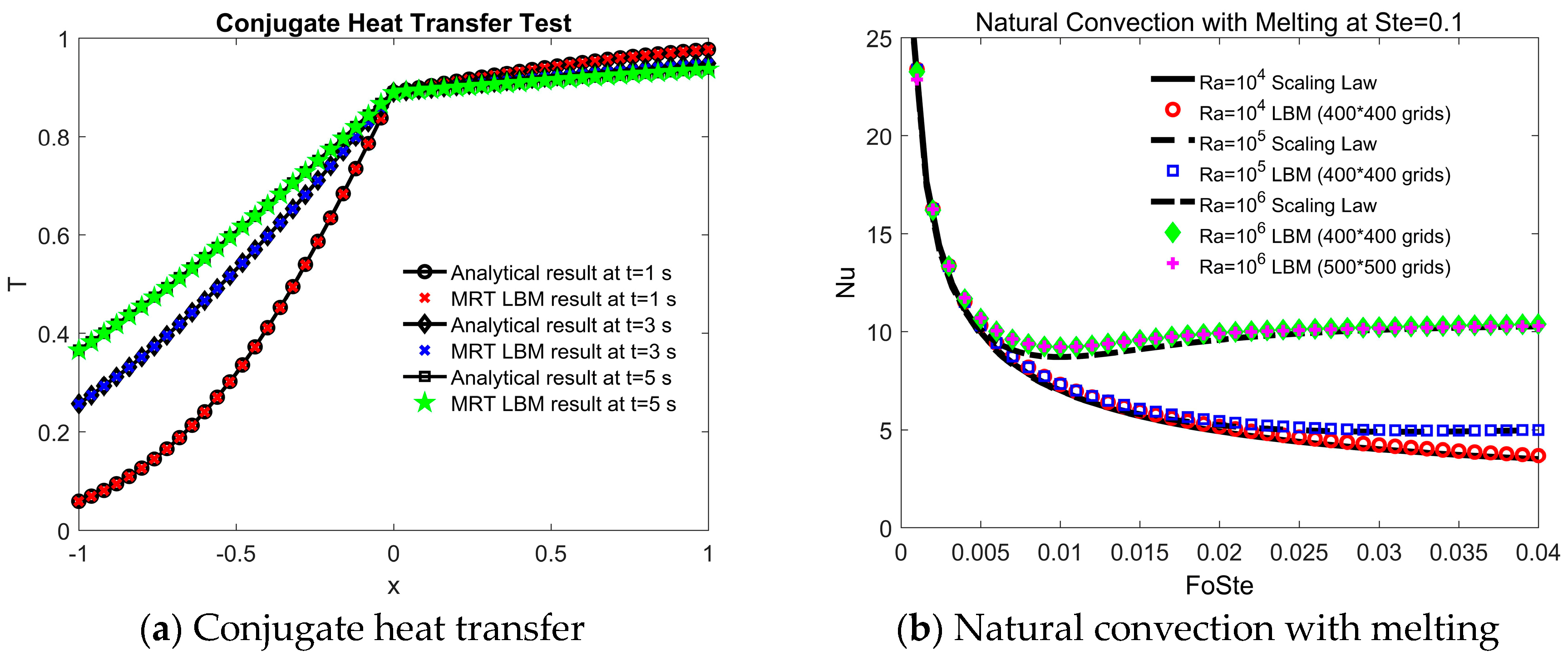
The Compute Unified Device Architecture (CUDA) Fortran code accelerated by GPU was developed in the current work. The details of CUDA implementation are presented in detail in our previous work [31]. Firstly, the code was validated using the one-dimensional conjugate heat transfer without a phase change between two materials. Initially, the temperature was set to be in the region A at and in the region B at . The analytical solution for this problem is given by [32]:
The thermophysical properties and prices of materials used in this work are presented in Table 1. For this calibration, the reinforced concrete was used for region A and paraffin (solid state) was chosen as the material for region B with the characteristic length of . The conjugate heat transfer problem was simulated by MRT LBM on GPU with the grid number of 100 100. As displayed in Figure 1a, the current results agree well with the analytical solutions, which demonstrate the accuracy of the current code for solving conjugate heat transfer problems. To calibrate the current program for the solid-liquid phase change problem, the code was coupled with a D2Q9 LBM solver for fluid flow and then the natural convection with melting at was simulated. Jany and Bejan applied the scaling laws to develop the correlation of an average Nusselt number, , of a hot wall for this problem, which is given as [33]:
As presented in Figure 1b, the current LBM code matched the results from the scaling laws at the Stefan number with different Rayleigh numbers when 400 400 grids were used. It indicated that the current code was accurate for modelling the solidification and melting processes.
3.3. Comprehensive Incremental Benefit Model
Compared to the traditional buildings, the green buildings with PCM or SIM have a larger incremental cost during the construction period. However, with their better energy saving characteristics, the green buildings will generate an economic benefit, an environmental benefit, and a social benefit during their lifetime. The comprehensive incremental benefit is defined as [34]:
where is the comprehensive incremental benefit, is the incremental benefit, and is the incremental cost for the extra expense of constructing the green building compared with the traditional building, which is expressed as:
is the cost of integrating extra materials such as PCM or SIM:
where is the price of PCM or SIM as shown in Table 1, is the price of other adhesive materials, which was chosen to be and was the labor fee. was the length of the roof set to be , is the width of the roof set to be , and is the thickness of PCM or SIM layer. is the cost for numerical modelling and consultation for the building design, which is . The incremental benefit is calculated as:
is the annual income discount rate coefficient given as:
is the year of the building life cycle, which is 50 years according to the standard of the Chinese government; is the discount rate, which is set to be = 11% for the Shaanxi province in China. The annual benefit is defined as:
is the economic benefit of green building:
where () is the energy saving amount during the summer AC cooling time, and () is the energy saving amount during the winter AC heating time. In this paper, the period of summer cooling and winter heating was chosen to be 70 days for each. is the Energy Efficiency Ratio (EER) or Coefficient of Performance (COP) of an air conditioner, which was set as 3.3 in this work. is the electricity price in the city of Hanzhong, Shaanxi Province which is .
is the environmental benefit of a green building and it includes the benefits generated by the reduction of , , and emissions. Using an effective equivalent method, the coefficient for transferring the saved electricity of the green building to the reduced combustion amount of coal was . The emission coefficients of , and smoke dust were , , respectively. Furthermore, the economic value for the reduced emissions of , and smoke dust were , , , and . Hence, the environmental benefit of a green building’s roof, is given as:
is the social benefit of the green building’s roof and it includes the reduced investment for electrical power installation and the economic loss due to the electricity consumption peak. From an investigation in China, when the electricity consumption decreases by , the electrical investment is reduced by and the economic loss decreases by . Then, the social benefit of a green building’s roof, , is computed by:
4. Results and Discussions
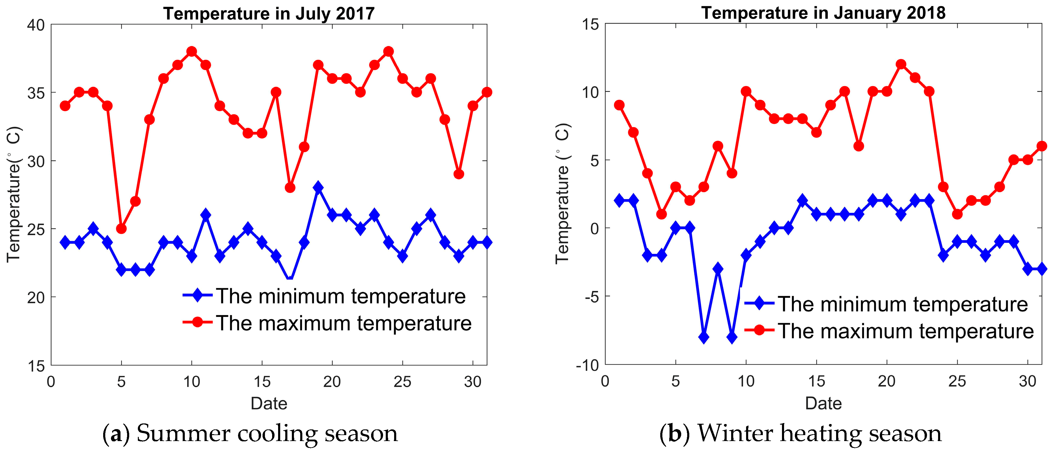
The city of Hanzhong in Shaanxi province was chosen to be a representative of a hot summer and cold winter region in China. The temperature of Hanzhong during July 2017 and January 2018 is presented in Figure 2. The average maximum temperature and minimum temperature for summertime in Hanzhong is 33.97 and respectively while it is and respectively for winter time. During the summertime, the average solar radiation intensity in the daytime is and the sunrise time is 6:00 a.m. while the sunset time is 20:00 p.m. During the winter time, the average solar radiation intensity in the daytime is , and the sunrise time is 8:00 a.m. while the sunset time is 17:00 p.m. The environmental temperature, , is expressed by using a sinusoidal function as follows [35]:
where is the maximum temperature during a day, is the minimum temperature during a day, and is the time. Similarly, the solar radiation intensity during daytime is given as:
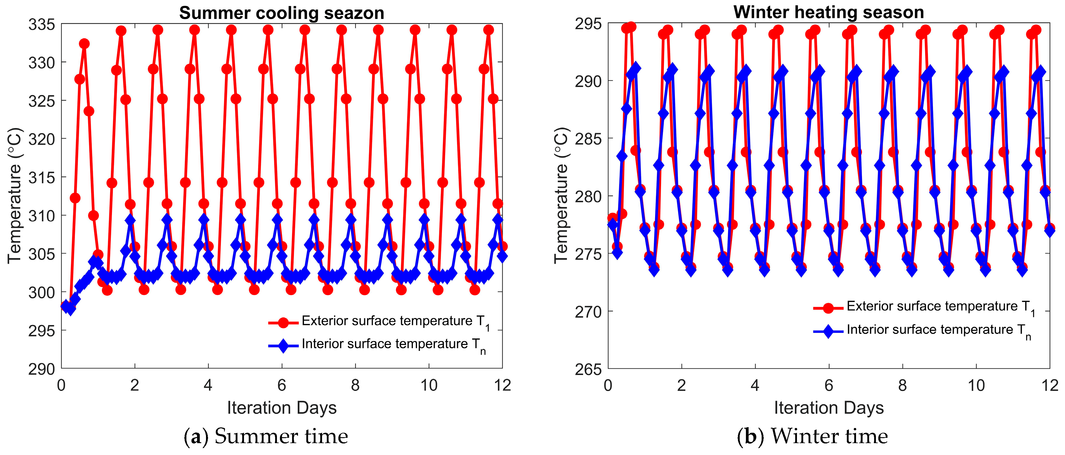
The current research investigated the energy saving characteristics of a PCM roof under the influence of solar radiation with intermittent air conditioner (AC) working conditions. During the AC working time, the internal room temperature, , was set to be for the summer cooling season while it was for the winter heating season. During the AC off time, the windows of the building were open so that the internal room temperature, , was equal to the environmental temperature . In order to eliminate the effect of the initial roof temperature on the energy consumption results, the computation was iterated for 10 days (240 h) until the temperature of the roof exhibited a periodic variation as shown in Figure 3.
4.1. The Influence of Roof Type
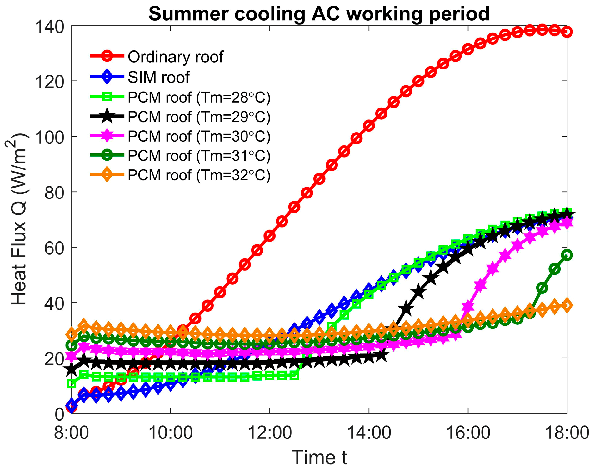
Paraffin was used as the phase change material (PCM) while perlite was chosen to be the sensible insulation material (SIM) for the roofs in the current work because of their similar thermophysical properties for a fair comparison as shown in Table 1. The energy saving characteristics of an ordinary roof (without PCM or SIM), SIM roof, and PCM roof during the summer cooling season were compared. As shown in Figure 4, the magnitudes of the heat flux, , for different types of roofs during the air conditioner cooling period are presented. The results indicate that the heat flux, , of an ordinary roof increases much more dramatically during the daytime compared with a SIM roof and a PCM roof, which indicates its larger energy consumption. By integrating the heat flux magnitude, , with respect to time, , during the AC working period, the energy consumption of an ordinary roof was . As a comparison, the heat flux magnitude, , of a SIM roof increased more smoothly due to the existence of a SIM layer with a low thermal conductivity, as displayed in Figure 4. For a SIM layer thickness of , the energy consumption of a SIM roof during the AC cooling time was . It means that the energy consumption of the roof decreased by when the SIM layer was inserted into the roof compared with the ordinary roof. In contrast to the ordinary roof and the SIM roof, as presented in Figure 4, the heat flux magnitude, , of a PCM roof remained constant for a long time under the influence of environmental temperature and solar radiation. As a consequence, when the PCM layer thickness was 30 mm, with a melting temperature of , the energy consumption of the PCM roof during the AC cooling time was , which is 63.36 and 18.99% lower than those of the ordinary roof and the SIM roof respectively. Under this circumstance, it should be concluded that the PCM roof had the best energy saving characteristic during the summer AC cooling time among all the three type roofs.
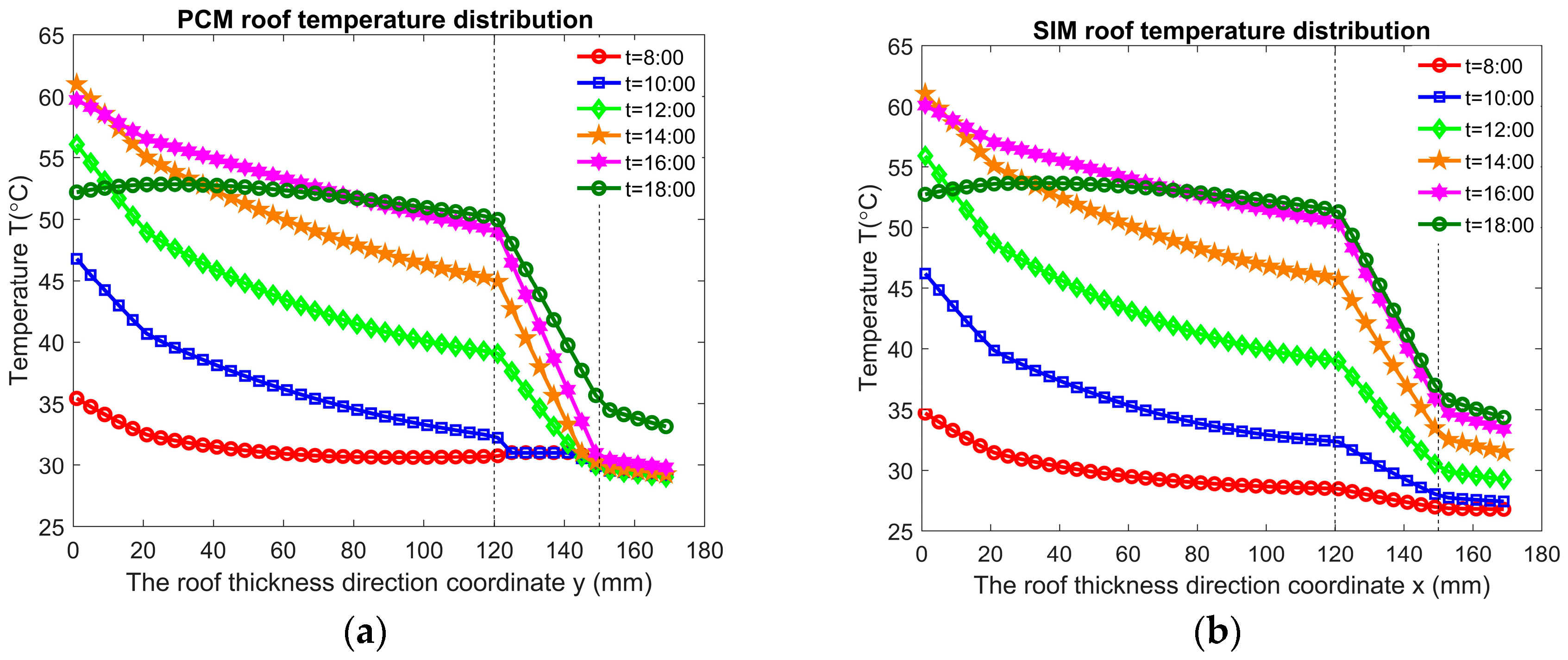
To further explain and understand the reason that a PCM roof has the minimum energy consumption during the summer cooling season, the temperature distributions of a PCM roof and a SIM roof ( and ) during the AC working period are shown in Figure 5. As presented in Figure 5, under the combined influences of the increasing environmental temperature and the solar radiation intensity, , the exterior surface temperature of the building’s roof increased during the daytime and achieved the maximum value at 14:00 p.m. Due to the latent heat characteristic of the PCM layer, the interior surface temperature of the PCM roof () remained almost unchanged until 16:00 p.m. However, when the PCM layer was fully melted and became a liquid, it behaved like the sensible insulation material and lost the latent heat characteristic. Hence, the temperature of the PCM roof interior surface could not be fixed at a relatively constant value and began to increase as shown by the curve at 17:00 p.m. On the other hand, although the low thermal conductivity of the SIM layer could prevent the heat loss to some extent compared with the ordinary roof, its internal surface temperature increased continuously, which actually consumed more energy for the air conditioner to cool down the room than the PCM roof.
4.2. The Influence of PCM Melting Temperature
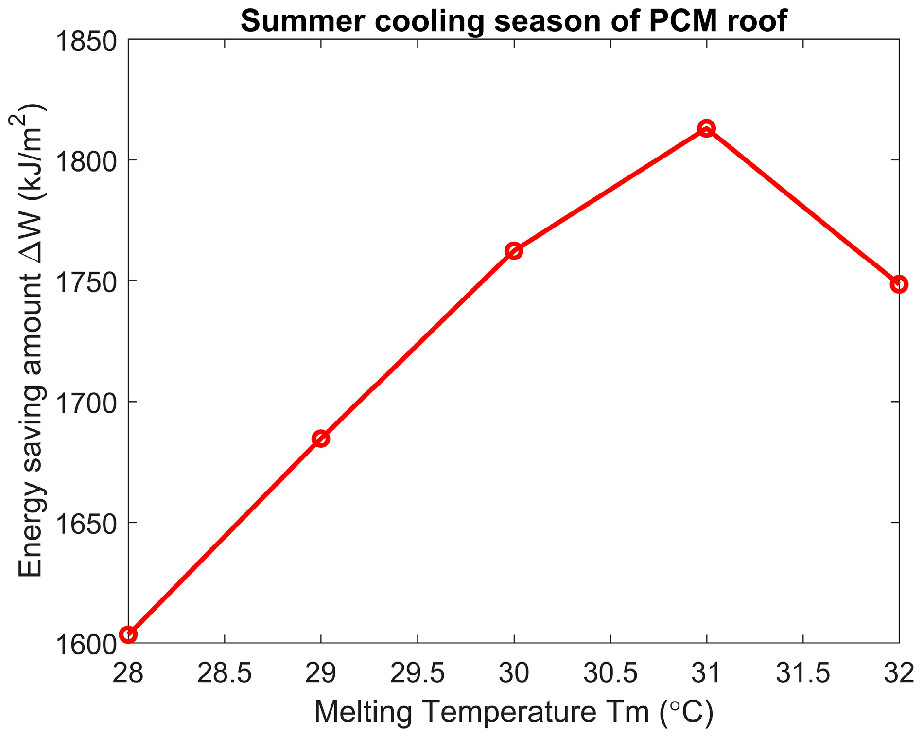
As one of the most significant factors of PCMs, which affects their thermal performance, the melting temperature, , of the PCM layer plays an essential role in the energy saving characteristics of a PCM roof. The energy saving amount, , of a PCM roof in terms of the melting temperature, , is plotted in Figure 6. It shows that the energy saving amount firstly increased with the increment of the melting temperature, , and it reached the optimum value at . As the melting temperature, , further increased to be higher than , the energy saving amount value of the PCM roof became less. When the melting temperature, , was , , , , and , the PCM roof energy saving amount, , during the summer cooling season was , , , , and respectively. Compared to the roof of , the energy saving amount, , for the roof with was increased by . The above discussion indicates that using the PCMs with an appropriate melting temperature, according to climate conditions, is important for optimizing the energy consumption characteristics of PCM roof buildings.
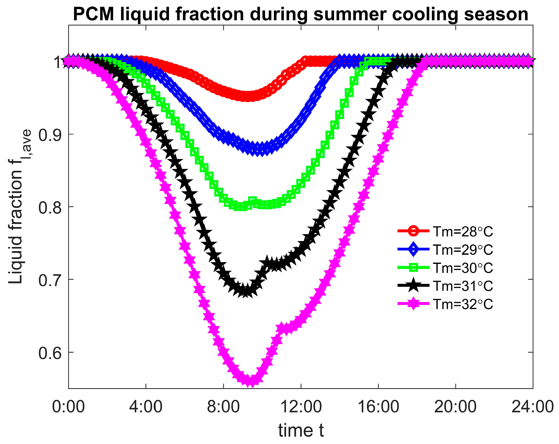
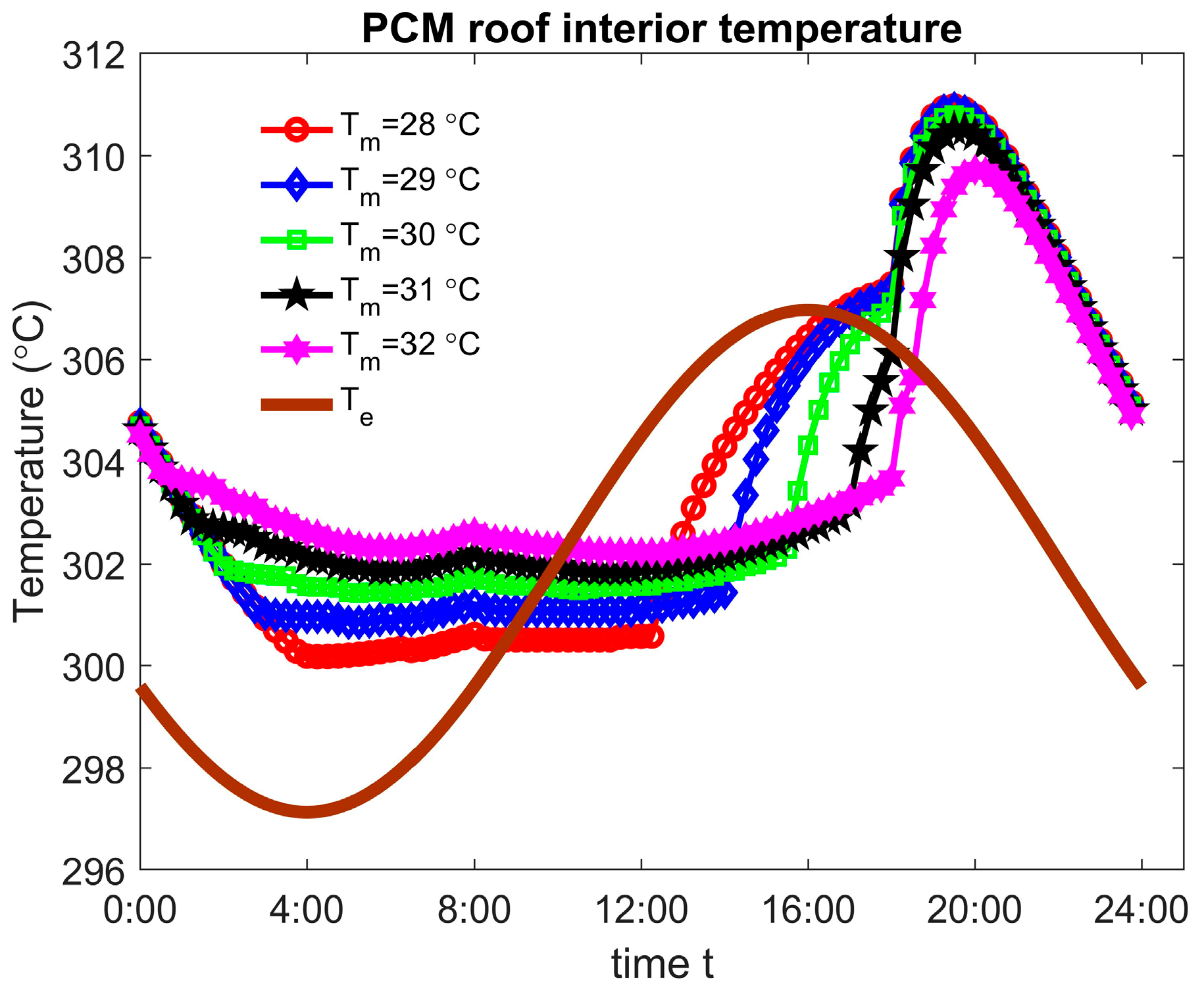
To explain the mechanism, an optimum PCM melting temperature for reducing the roof energy consumption amount exists, the transient PCM average liquid fraction during the summer cooling season is plotted in Figure 7. At a melting temperature of , it was found that only 4.8% of the amount of PCM solidified during the early morning time and all of the PCM became liquid again at 12:15 p.m. When the PCM layer became fully liquid, it lost the latent heat characteristic and behaved like the SIM layer so that the internal temperature inside the PCM roof could not be controlled and started to increase at this state. Contrary to the PCM roof with a melting temperature , the maximum solid state PCM amount was during the early morning for the PCM roof with under which situation the energy storage capacity of the PCM layer increased. For this reason, the time for a PCM layer of being fully melted to a liquid state was delayed to 17:00 p.m. The means that the interior surface temperature of a PCM roof could be fixed at a nearly constant value until 17:00 p.m. so that the energy consumption from using the air conditioner was highly reduced. Unfortunately, as the melting temperature was further increased to , the PCM layer did not become fully liquid until 18:30 p.m. Although the PCM layer of had the capability of modulating the temperature inside the PCM roof during the whole AC working period, this PCM layer also solidified more rapidly at a relatively higher solidification temperature during the nighttime and the early morning time from 0:00 a.m. to 9:00 a.m., as shown in Figure 7. This phenomenon makes the PCM layer have a trade-off effect on the energy saving characteristics of a PCM roof: (1) A relatively higher melting temperature, , could make the PCM layer have a longer latent heat characteristic, which delays the temperature rise in the PCM roof during the daytime so that the energy consumption of the air conditioner is reduced. (2) The PCM layer with a higher melting temperature, , solidified more rapidly during the nighttime at a nearly constant temperature. Hence, its temperature could not be further cooled down by the lower environment temperature, , under which the air conditioner energy cost during the daytime increased. The variations of the PCM roof interior surface temperature, , and the corresponding environmental temperature, , are displayed in Figure 8. Although the interior surface temperature rise of the PCM roof with a melting temperature could be delayed more than the other PCM roofs, its interior surface temperature, , during the nighttime was the highest. Furthermore, during the nighttime, the environmental temperature, , was much lower than the melting temperature of the PCM roofs in the current work, which means that the environmental temperature could cool down the temperature inside the roof. Based on this, a higher melting temperature of a PCM roof at nighttime has a negative contribution to the energy saving amount of the PCM roof. Hence, by balancing the trade-off influence of the PCM layer melting temperature during the daytime and nighttime, an optimum melting temperature, , exists, which was in this work for a PCM roof to reduce the maximum amount of energy consumption. For the remainder of the paper, the melting temperature of was used.
4.3. The Influence of PCM or SIM Layer Thickness
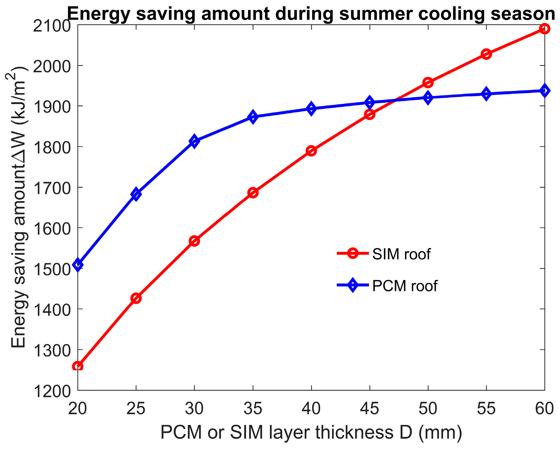
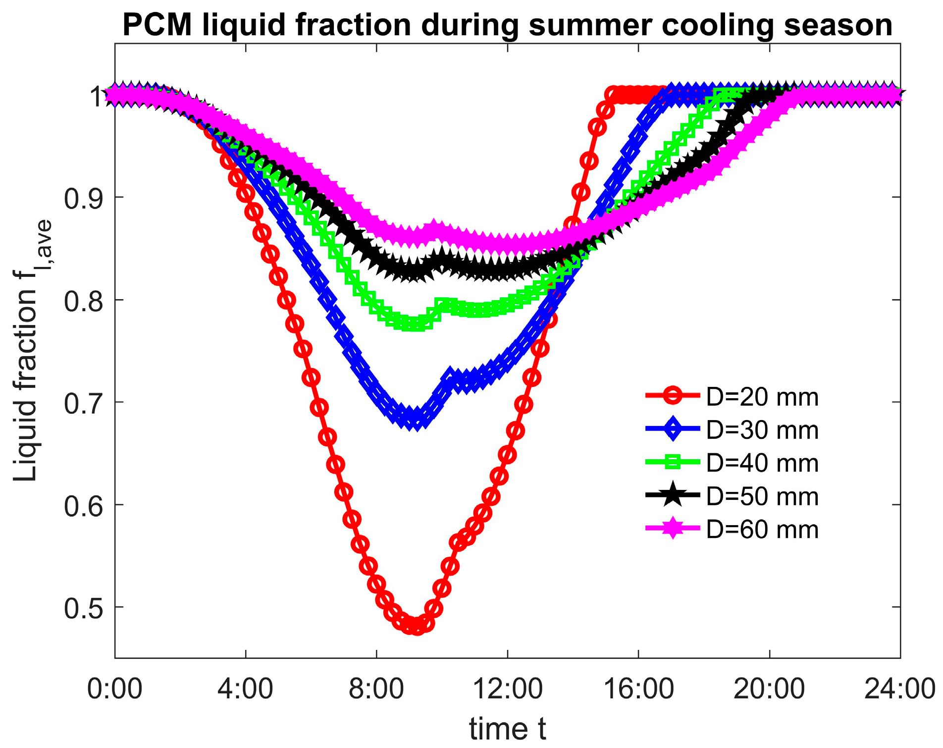
The PCM or SIM layer thickness not only affected the energy saving characteristics of green building roofs but also determined its incremental cost during the construction period and the corresponding building’s comprehensive incremental benefit. In Figure 9, the effect of PCM or SIM layer thickness on the energy saving amount of a green building’s roof is plotted. The energy saving characteristics of both PCM roof and SIM roof improve with the increment of their PCM or SIM layer thicknesses. The results indicate that the energy saving amount, , of a SIM roof increases almost linearly with respect to the increasing SIM layer thickness because of the linearly increased thermal resistance. contrary to the SIM layer, the increasing the rate of the energy saving amount, , of a PCM roof decreased in terms of the PCM layer thickness and its energy saving amount almost approached a constant value when the PCM layer thickness is large. To clarify the underlying mechanism of this situation, the average liquid fraction of a PCM layer during the summer cooling time is shown in Figure 10. It was found that the energy storage capacity of a latent heat PCM layer increased with its increasing layer thickness. For the PCM layer of , the PCM became fully melted and lost the capability of controlling the roof temperature at 15:15 p.m. As a consequence, the interior roof surface temperature began to rise after 15:15 p.m., which increased the energy consumption of the PCM roof. In comparison, when the PCM layer of was used, the inside roof temperature was modulated by the PCM layer until 21:00 p.m., which guaranteed that the PCM layer had the latent heat characteristic during the air conditioner working time so that the maximum energy saving amount was achieved. However, similar to the discussion in Section 4.2 for the effect of PCM melting temperature, the increment of the PCM layer thickness also had a negative influence on the energy saving capability of the PCM roof. As the environmental temperature became low during the nighttime, the latent heat function of the PCM layer at nighttime, after 18:00 p.m., maintained its temperature nearly at the solidification point, which prevented heat transfer from the internal roof region into the environment. As a consequence, due to the trade-off effect of the PCM layer thickness, the increasing rate of the energy saving amount of a PCM roof decreases. Besides, when the PCM or SIM layer thickness was , the energy saving amount of the PCM roof was more than that of the SIM roof because of the latent heat characteristic of the PCM layer, which attenuated the temperature oscillation inside the roof. However, it is interesting to note that the SIM roof had a better energy saving capability than the PCM roof when their layer thickness, , was more than . The reason for this phenomenon is that a SIM roof with larger thickness could prevent the heat transfer from the environment into the interior room in the daytime and the interior SIM roof temperature could also be efficiently cooled down without the effect of latent heat during the nighttime, which makes the SIM roof have a different thermal performance compared to the PCM roof.
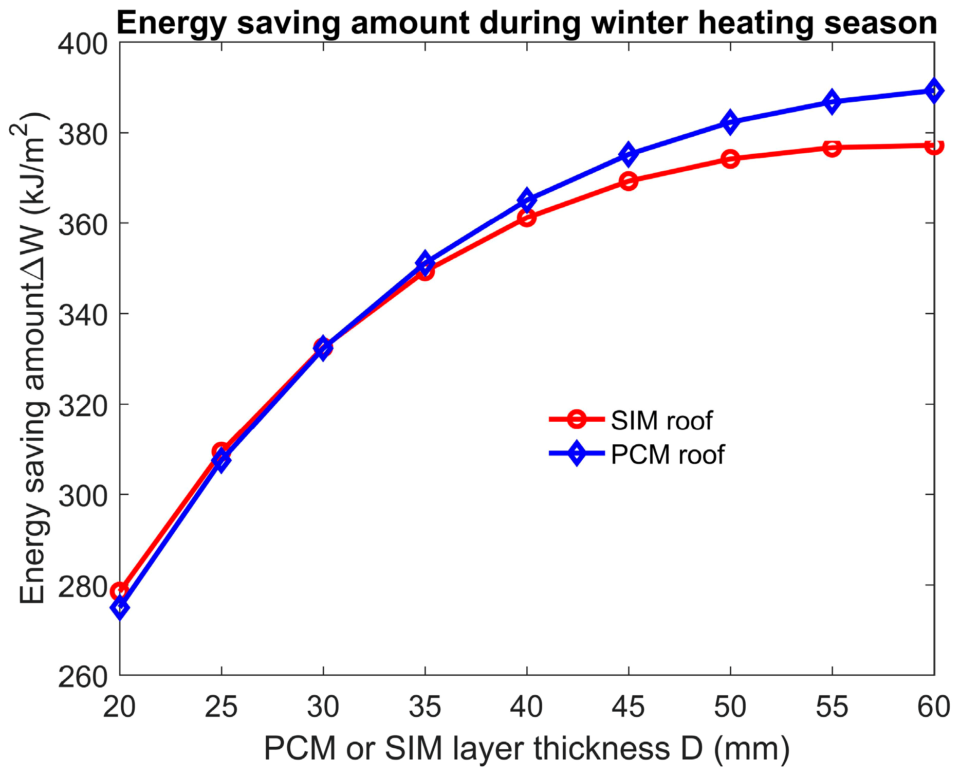
In order to evaluate the comprehensive incremental benefit of a green roof building during the life cycle in a hot summer and cold winter region of China, the energy saving amount of a PCM roof and a SIM roof during the winter AC heating season should also be investigated. When the PCM layer with a melting temperature was inserted into the green building roof, it was kept in the solid state without melting and solidification processes in Hanzhong city during the winter AC heating time. As a result, the PCM layer did not have the capability of modulating the temperature change inside the roof with latent heat and its function was similar to the sensible insulation material with a low thermal conductivity. As the thermal conductivities of paraffin (PCM) and perlite (SIM) used in this work were similar, the energy saving amounts of a PCM roof and SIM roof were almost the same when the layer thickness, , was less than
as shown in Figure 11. However, the specific heat, , of perlite is much larger than that of paraffin. When the thicknesses of a PCM roof and a SIM roof were large, the interior surface temperature rise inside the SIM perlite roof was much slower than that inside the PCM paraffin roof during the daytime under the influence of solar radiation. Hence, as displayed in Figure 11, it costs more energy for heating the room of a SIM roof using the air conditioner than that of a PCM roof.
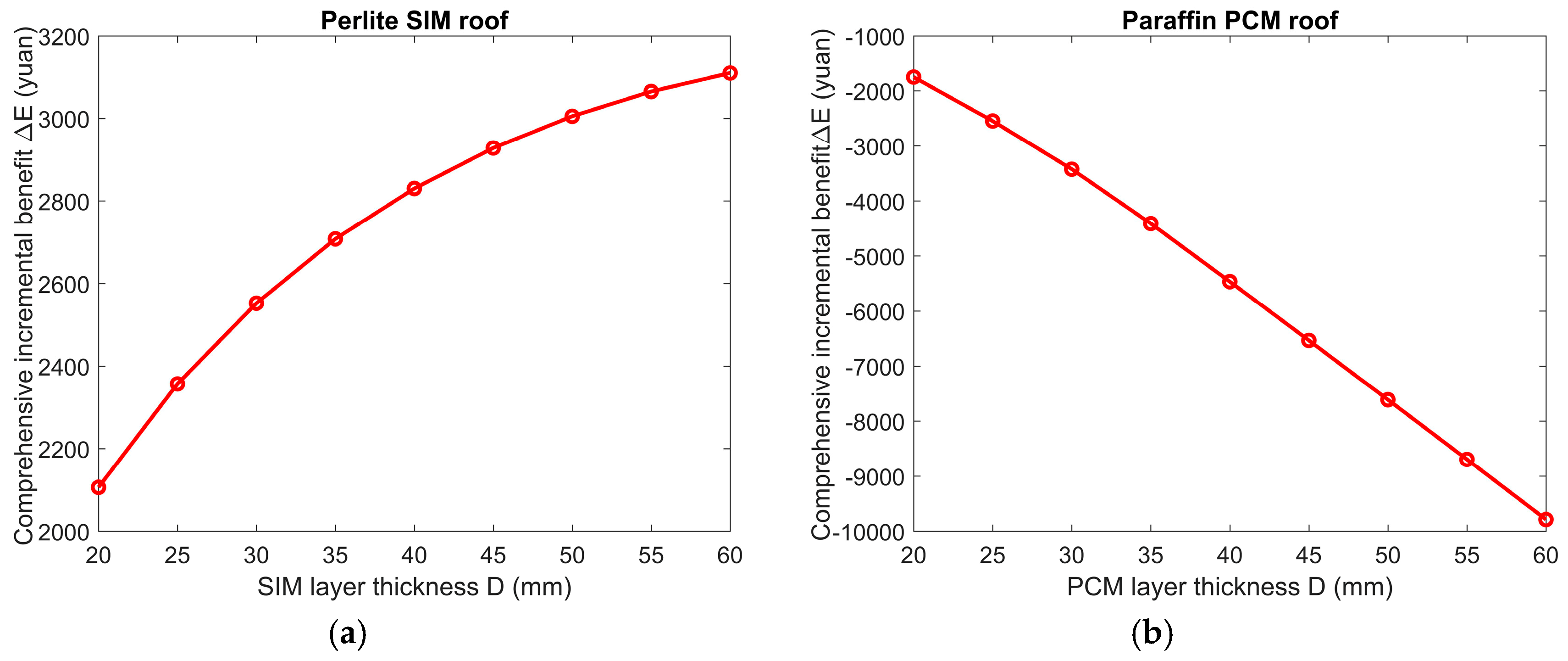
From the above discussions, due to the effect of latent heat, the PCM layer could modulate the temperature inside the building roof and improve the thermal comfort in the room and its energy saving capability was also better than the SIM roof if the appropriate PCM melting temperature and PCM layer thickness were chosen. However, besides the energy saving capability of green building roofs, its incremental cost in the construction period and the incremental benefit during the operational period are significant in practical engineering. The comprehensive incremental benefits of a paraffin PCM roof and a perlite SIM roof during life cycle with different PCM or SIM layer thicknesses are shown in Figure 12. The data indicate that the perlite SIM roof has a positive comprehensive incremental benefit for all the different SIM layer thicknesses. When the SIM layer with a thickness of was used, the SIM roof achieved the maximum comprehensive incremental benefit of . On the contrary, the comprehensive incremental benefit of a paraffin PCM roof was always negative, which indicates that the paraffin PCM roof could not have an economic benefit so that it is not proper for the practical engineering application at the current stage. The reason for the huge difference between the comprehensive incremental benefit of a paraffin PCM roof and a perlite SIM roof was that the material price of paraffin is 24.14 times more than that of perlite as shown in Table 1. In this case, developing cheap PCMs with stable chemical properties is a key scientific bottleneck for wide engineering applications of PCM envelope building in recent future.
5. Conclusions
In this paper, an enthalpy-based multiple-relaxation-time (MRT) lattice Boltzmann method (LBM) was developed with GPU acceleration to investigate the conjugate heat transfer and solid-liquid phase change inside the PCM roof. To demonstrate the advantage of a PCM roof with latent heat properties for improving the building’s thermal comfort, the energy saving characteristics of a PCM roof and a SIM roof under different conditions were compared. It was found that the latent heat of PCM had a trade-off effect on the energy saving characteristics of a building’s roof. Under this circumstance, an optimum PCM melting temperature for the PCM roof exists to achieve the maximum energy saving amount. Besides, the PCM or SIM layer thickness also had obvious effects on the thermal performance of the PCM or SIM roof. The energy saving amount of the SIM roof increased linearly with the increasing SIM layer thickness due to the enhanced thermal resistance. However, the increasing rate for the PCM roof energy saving amount decreased with the increment of the PCM layer thickness because of the trade-off influences of latent heat during the daytime and nighttime. In general, a PCM roof could exhibit a better thermal performance than the SIM roof for reducing energy consumption when the appropriate melting temperature and layer thickness are chosen. Unfortunately, due to the high price of PCMs, the comprehensive incremental benefit of a PCM roof is much lower than that of a SIM roof. To make the wide application of PCM envelope building in practical engineering, the PCMs with a low price and stable chemical properties should be developed in future scientific research.
Author Contributions
Conceptualization, B.S. and Q.R.; Methodology, X.D.; Validation, X.D.; Formal Analysis, X.D.; Investigation, X.D.; Writing-Original Draft Preparation, X.D.; Supervision, B.S.; Funding Acquisition, B.S. and Q.R.
Funding
This research was funded by the National Natural Science Foundation of China (No. 51806168) and China Post-doctoral Science Foundation (No. 2017M623169).
Conflicts of Interest
The authors declare no conflict of interest.
References
- Erdem, C.; Young, C.H.; Saffa, B.R. Performance investigation of heat insulation solar glass for low-carbon buildings. Energy Convers. Manag. 2014, 88, 834–841. [Google Scholar]
- Kong, X.; Lu, S.; Li, Y.; Huang, J.; Liu, S. Numerical study on the thermal performance of building wall and roof incorporating phase change material panel for passive cooling application. Energy Build. 2014, 81, 404–415. [Google Scholar] [CrossRef]
- Li, D.; Zheng, Y.; Liu, C.; Wu, G. Numerical analysis on thermal performance of roof contained PCM of a single residential building. Energy Convers. Manag. 2015, 100, 147–156. [Google Scholar] [CrossRef]
- Baetens, R.; Jelle, B.P.; Gustavsen, A. Phase change materials for building applications: A state-of-the-art review. Energy Build. 2010, 42, 1361–1368. [Google Scholar] [Green Version]
- Zhou, D.; Zhao, C.Y.; Tian, Y. Review on thermal energy storage with phase change materials (PCMs) in building applications. Appl. Energy 2012, 92, 593–605. [Google Scholar] [Green Version]
- Akeiber, H.; Nejat, P.; Majid, M.Z.A.; Wahid, M.A.; Jomehzadeh, F.; Famileh, I.Z.; Calautit, J.K.; Hughes, B.R.; Zaki, S.A. A review on phase change material (PCM) for sustainable passive cooling in building envelopes. Renew. Sustain. Energy Rev. 2016, 60, 1470–1497. [Google Scholar] [CrossRef]
- Al-Saadi, S.N.; Zhai, Z.J. Modeling phase change materials embedded in building enclosure: A review. Renew. Sustain. Energy Rev. 2013, 21, 659–673. [Google Scholar] [CrossRef]
- Izquierdo-Barrientos, M.A.; Belmonte, J.F.; Rodríguez-Sánchez, D.; Molina, A.E.; Almendros-Ibáñez, J.A. A numerical study of external building walls containing phase change materials (PCMs). Appl. Therm. Eng. 2012, 47, 73–85. [Google Scholar] [CrossRef]
- Zwanzig, S.D.; Lian, Y.; Brehob, E.G. Numerical simulation of phase change material composite wallboard in a multi-layered building envelope. Energy Convers. Manag. 2013, 69, 27–40. [Google Scholar] [CrossRef]
- Jin, X.; Medina, M.A.; Zhang, X. Numerical analysis for the optimal location of a thin PCM layer in frame walls. Appl. Therm. Eng. 2016, 103, 1057–1063. [Google Scholar] [CrossRef] [Green Version]
- Xie, J.; Wang, W.; Liu, J.; Pan, S. Thermal performance analysis of PCM wallboards for building application base on numerical simulation. Sol. Energy 2018, 162, 533–540. [Google Scholar] [CrossRef]
- Tokuç, A.; Başaran, T.; Yesügey, S.C. An experimental and numerical investigation on the use of phase change materials in building elements: The case of a flat roof in Istanbul. Energy Build. 2015, 102, 91–104. [Google Scholar] [CrossRef] [Green Version]
- Liu, C.; Zhou, Y.; Li, D.; Meng, F.; Zheng, Y.; Liu, X. Numerical analysis on thermal performance of a PCM-filled double glazing roof. Energy Build. 2016, 125, 267–275. [Google Scholar] [CrossRef]
- Chen, S.; Doolen, G.D. Lattice Boltzmann method for fluid flows. Annu. Rev. Fluid Mech. 1998, 30, 329–364. [Google Scholar] [CrossRef]
- Aidun, C.K.; Clausen, J.R. Lattice-Boltzmann method for complex flows. Annu. Rev. Fluid Mech. 2010, 42, 439–472. [Google Scholar] [CrossRef]
- Miller, W. The lattice Boltzmann method: A new tool for numerical simulation of the interaction of growth kinetics and melt flow. J. Cryst. Growth 2001, 230, 263–269. [Google Scholar] [CrossRef]
- Rasin, I.; Miller, W.; Succi, S. Phase-field lattice kinetic scheme for the numerical simulation of dendritic growth. Phys. Rev. E 2005, 72, 066705. [Google Scholar] [CrossRef] [PubMed]
- Huang, R.; Wu, H. An immersed boundary-thermal lattice Boltzmann method for solid-liquid phase change. J. Comput. Phys. 2014, 277, 305–319. [Google Scholar] [CrossRef]
- Jiaung, W.S.; Ho, J.R.; Kuo, C.P. Lattice Boltzmann method for the heat conduction problem with phase change. Numer. Heat Transf. Part B Fundam. 2001, 39, 167–187. [Google Scholar]
- Eshraghi, M.; Felicelli, S.D. An implicit lattice Boltzmann model for heat conduction with phase change. Int. J. Heat Mass Transf. 2012, 55, 2420–2428. [Google Scholar] [CrossRef]
- Huang, R.; Wu, H.; Cheng, P. A new lattice Boltzmann model for solid-liquid phase change. Int. J. Heat Mass Transf. 2013, 59, 295–301. [Google Scholar] [CrossRef]
- Huang, R.; Wu, H. Phase interface effects in the total enthalpy-based lattice Boltzmann model for solid-liquid phase change. J. Comput. Phys. 2015, 294, 346–362. [Google Scholar] [CrossRef]
- Li, D.; Ren, Q.; Tong, Z.X.; He, Y.L. Lattice Boltzmann models for axisymmetric solid-liquid phase change. Int. J. Heat Mass Transf. 2017, 112, 795–804. [Google Scholar] [CrossRef]
- Li, D.; Tong, Z.X.; Ren, Q.; He, Y.L.; Tao, W.Q. Three-dimensional lattice Boltzmann models for solid-liquid phase change. Int. J. Heat Mass Transf. 2017, 115, 1334–1347. [Google Scholar] [CrossRef]
- Ren, Q.; Chan, C.L. Numerical study of double-diffusive convection in a vertical cavity with Soret and Dufour effects by lattice Boltzmann method on GPU. Int. J. Heat Mass Transf. 2016, 93, 538–553. [Google Scholar] [CrossRef]
- Ren, Q.; Meng, F.; Guo, P. A comparative study of PCM melting process in a heat pipe-assisted LHTES unit enhanced with nanoparticles and metal foams by immersed boundary-lattice Boltzmann method at pore-scale. Int. J. Heat Mass Transf. 2018, 121, 1214–1228. [Google Scholar] [CrossRef]
- Ren, Q. Investigation of pumping mechanism for non-Newtonian blood flow with AC electrothermal forces in a microchannel by hybrid boundary element method and immersed boundary-lattice Boltzmann method. Electrophoresis 2018, 39, 1329–1338. [Google Scholar] [CrossRef] [PubMed]
- Ren, Q.; He, Y.L.; Su, K.Z.; Chan, C.L. Investigation of the effect of metal foam chracteristics on the PCM melting performance in a latent heat thermal energy storage unit by pore-scale lattice Boltzmann modelling. Numer. Heat Transf. Part A Appl. 2017, 72, 745–764. [Google Scholar] [CrossRef]
- Ren, Q. Bioparticle delivery in physiological conductivity solution using AC electrokinetic micropump with castellated electrodes. J. Phys. D Appl. Phys. 2018. [Google Scholar] [CrossRef]
- Ren, Q.; Meng, F.; Chan, C.L. Cell transport and suspension in high conductivity electrothermal flow with negative dielectrophoresis by immersed boundary-lattice Boltzmann method. Int. J. Heat Mass Transf. 2019, 128, 1129–1244. [Google Scholar] [CrossRef]
- Ren, Q.; Chan, C.L. Natural convection with an array of solid obstacles in an enclosure by lattice Boltzmann method on a CUDA computation platform. Int. J. Heat Mass Transf. 2016, 93, 273–285. [Google Scholar] [CrossRef]
- Ren, Q.; Chan, C.L. GPU accelerated numerical study of PCM melting process in an enclosure with internal fins using lattice Boltzmann method. Int. J. Heat Mass Transf. 2016, 100, 522–535. [Google Scholar] [CrossRef]
- Jany, P.; Bejan, A. Scaling theory of melting with natural convection in an enclosure. Int. J. Heat Mass Transf. 1988, 31, 1221–1235. [Google Scholar] [CrossRef]
- Li, J.; Tian, Z. Incremental cost-benefit of life cycle green buildings. J. Eng. Manag. 2011, 5, 004. [Google Scholar]
- Ballim, Y. A numerical model and associated calorimeter for predicting temperature profiles in mass concrete. Cem. Concr. Compos. 2004, 26, 695–703. [Google Scholar] [CrossRef]
Figure 1.
CUDA code calibration for conjugate heat transfer and solid-liquid phase change.

Figure 2.
The temperature variation of Hanzhong city.

Figure 3.
Iteration process of the roof temperature during the computation.

Figure 4.
Heat flux magnitude of different types of roofs during the summer AC cooling time.

Figure 5.
The PCM roof and SIM roof temperature distribution during the summer AC cooling time.

Figure 6.
The effect of the melting temperature on the PCM roof energy saving amount.

Figure 7.
The PCM layer average liquid fraction during the summer cooling season at different melting temperatures.
Figure 7.
The PCM layer average liquid fraction during the summer cooling season at different melting temperatures.

Figure 8.
The PCM roof interior surface temperature during the summer cooling season at different melting temperatures.
Figure 8.
The PCM roof interior surface temperature during the summer cooling season at different melting temperatures.

Figure 9.
The effect of layer thickness on the energy saving amount of PCM or SIM roofs during the summer cooling season.
Figure 9.
The effect of layer thickness on the energy saving amount of PCM or SIM roofs during the summer cooling season.

Figure 10.
The PCM layer average liquid fraction during the summer cooling season with different layer thicknesses.
Figure 10.
The PCM layer average liquid fraction during the summer cooling season with different layer thicknesses.

Figure 11.
The effect of layer thickness on the energy saving amount of PCM or SIM roofs during the winter heating season.
Figure 11.
The effect of layer thickness on the energy saving amount of PCM or SIM roofs during the winter heating season.

Figure 12.
The comprehensive incremental benefit of a SIM roof and a PCM roof during the life cycle.
Figure 12.
The comprehensive incremental benefit of a SIM roof and a PCM roof during the life cycle.


Table 1.
Thermophysical properties and prices of materials in a building’s roof (Data resource: China Chemical Engineering Website).
Table 1.
Thermophysical properties and prices of materials in a building’s roof (Data resource: China Chemical Engineering Website).
| Material | ||||
|---|---|---|---|---|
| Cement | ||||
| Concrete | - | |||
| Paraffin | ||||
| Perlite | 350 | |||
| Lime |
© 2018 by the authors. Licensee MDPI, Basel, Switzerland. This article is an open access article distributed under the terms and conditions of the Creative Commons Attribution (CC BY) license (http://creativecommons.org/licenses/by/4.0/).
Share and Cite
MDPI and ACS Style
Shao, B.; Du, X.; Ren, Q. Numerical Investigation of Energy Saving Characteristic in Building Roof Coupled with PCM Using Lattice Boltzmann Method with Economic Analysis. Appl. Sci. 2018, 8, 1739. https://doi.org/10.3390/app8101739
AMA Style
Shao B, Du X, Ren Q. Numerical Investigation of Energy Saving Characteristic in Building Roof Coupled with PCM Using Lattice Boltzmann Method with Economic Analysis. Applied Sciences. 2018; 8(10):1739. https://doi.org/10.3390/app8101739
Chicago/Turabian StyleShao, Bilin, Xingxuan Du, and Qinlong Ren. 2018. "Numerical Investigation of Energy Saving Characteristic in Building Roof Coupled with PCM Using Lattice Boltzmann Method with Economic Analysis" Applied Sciences 8, no. 10: 1739. https://doi.org/10.3390/app8101739
Note that from the first issue of 2016, this journal uses article numbers instead of page numbers. See further details here.