A Weighted Turbo Equalized Multi-Band Underwater Wireless Acoustic Communications


1
Department of Radio Communication Engineering, Korea Maritime and Ocean University, Busan 606-791, Korea
2
Agency for Defense Development, P.O. Box 18, Jinhae-gu, Changwon-si, Gyengsangnam-do 51678, Korea
*
Author to whom correspondence should be addressed.
Appl. Sci. 2018, 8(10), 1711; https://doi.org/10.3390/app8101711
Submission received: 24 August 2018
/
Revised: 17 September 2018
/
Accepted: 18 September 2018
/
Published: 20 September 2018
(This article belongs to the Special Issue Recent Advances on Wireless Acoustic Sensor Networks (WASN))
Abstract
:The multi-band UWAS (Underwater Wireless Acoustic Sensor) communication techniques are effective in terms of performance and throughput efficiency because they can overcome selective frequency fading by allocating the same data to different frequency bands, in an environment of rapidly changing channel transfer characteristic. However, the multi-band configuration may have a performance worse than the single-band one because performance degradation in one particular band affects the output from all the other bands. This problem can be solved by using a receiving end that analyzes the error rates of each band, sets threshold values and allocates the lower weights to the inferior bands. There are many methods of setting threshold values. In this paper, we proposed an algorithm to set the threshold value by using the preamble error rates, which are known data that have to be transmitted and received. In addition, we have analyzed the efficiency of multi-band transmission scheme in the UWAS communication by applying 1~4 number of multi-bands, using turbo pi codes, with a coding rate of 1/3. We evaluated the performance of the proposed multi-bands transmission model in real underwater environments. Experimental results showed that the performance increased as the number of multiple bands increased. Furthermore, the performance of multi-band was improved when the proposed threshold algorithm was applied.
1. Introduction
In the past, underwater acoustic was utilized for military purpose such as submarine communications and for low-probability detection by third parties. Nowadays, underwater acoustic is considered to be one of the most challenging environments for data communications, such as control of autonomous underwater vehicles (AUV), and undersea command and control. The performance of UWAS (Underwater Wireless Acoustic Sensor) communication depends on factors such as propagation loss (according to the distance of acoustic signals), interference signal (caused by multi-path propagation), background noise, and Doppler effects (which are related to moving sound sources or sea surface roughness) [1,2,3]. Additionally, the increase in propagation distance decreases the bandwidth, which results in lower efficiency of data propagation. In the UWAS communication environment, multi-path propagation characteristics, or the Doppler-spread, affect the communication performances according to the spatiotemporal changes, including seabed, sea level, and water depth. Accordingly, channel coding and modem technologies are essential in designing a system that can overcome this challenge [4,5].
As a UWAS channel has time-varying characteristics, the multi-band communication technology [6,7,8], which allocates the same data to different frequency bands, has been recently highlighted because it overcomes the frequency-selective fading that occurs due to the underwater multi-path and the Doppler spread [9,10,11]. In other words, the multi-band communication technology overcomes various problems of underwater channel environments and extends the propagation distances, thereby, improving both the performance and the propagation efficiency. However, as long-distance communications use a narrow frequency band, the multi-band communication is based on a limited range of available frequencies. For military submarine applications, UWAS systems are required to remain undetected, be highly reliable, and require long-range communication. The goal of the multi-band underwater communication is to successfully transmit data in various underwater channel environments and extended propagation distances.
The research project of EUROPA “UUV Covert Acoustic Communications” tested, at a sea trial, using eight sub-bands with turbo coding techniques, at a data rate of 75 bps, had a range of up to 50 km [12]. In the multi-band transmission and reception structure of the reference [12], the turbo coded 5670 bits of each band and the preamble 2880 bits were divided into 45 and then the divided preamble bits and coded bits were sequentially arranged to form a single packet, which was iteratively propagated to each band. However, the multi-band configuration may have worse performance than the single-band one. It is because the performance degradation in a particular band affects the output from the entire bands, which is input into an encoder, thereby decreasing the overall performance. This problem can be solved through a receiving end that analyzes error rates of each band, sets threshold values and allocates lower weights to inferior bands. There are many methods of setting threshold values. This paper proposed to set threshold values by utilizing the preamble error rates, which are known data to be transmitted and received. In the receiver sides, after compensating frequency and phase offset in each band, iterative turbo equalizer is used in the system. The equalizer and turbo decoder are connected through the interleaving functions and de-interleaving that update each other’s information recursively. The interleaved output is canceled a posteriori from the proceeding received signal. Interleaving helps receiver convergence.
This paper analyzed the efficiency of multi-band acoustic propagation in UWAS communication. For the analysis, an underwater experiment was conducted by using a turbo pi code with 1/3 coding rate [13,14,15] and applying up to four bands. The experimental results showed that, as the number of multi-bands increased, the performance was improved. In addition, when four bands were used, the threshold values based on the preamble error rate achieved the best performance.
2. The Multi-Band Underwater Wireless Acoustic Sensor (UWAS) Communication
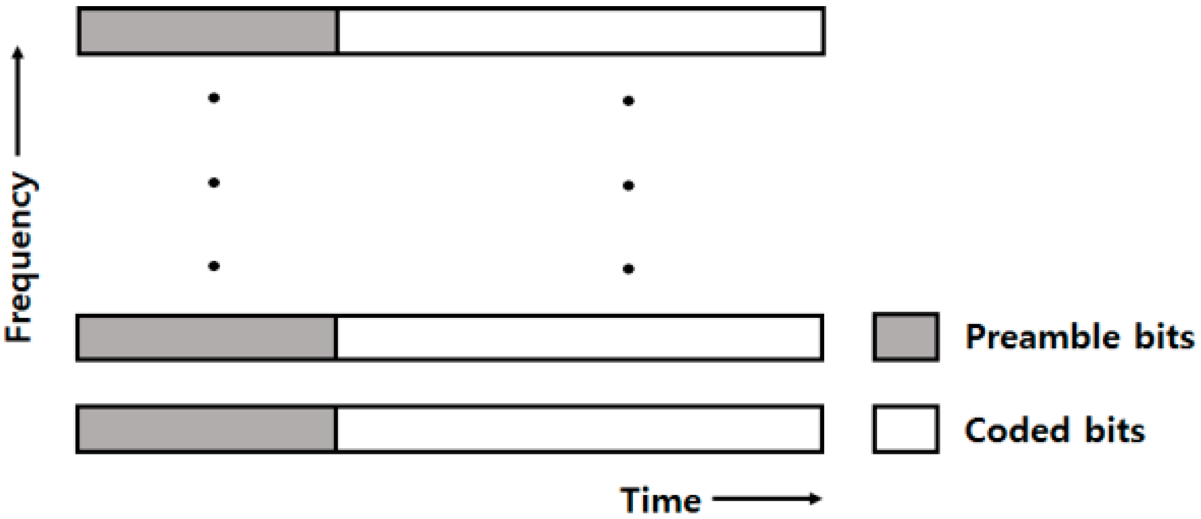
The multi-band acoustic propagation method uses frequency-selective fading to modulate signals that are to be transmitted into different frequencies, by dividing the same coded bit string in parallel. As shown in Figure 1, when coded bits are divided into each block and a preamble bit is input for synchronous acquisition, a single packet is created. Each packet, consisting of bits, is reorganized as packets, and then different frequencies, that is, different bands, are used to combine and propagate the modulated signals.
The packet structure is shown in Figure 1. This paper generated a single packet consisting of coded and preamble bits. Besides, the same packets were configured for multi-band acoustic propagations and different frequencies were used to add up and propagate the modulated signals.
2.1. Transmitter and Receiver Structure of the Multi-Band Underwater Communication
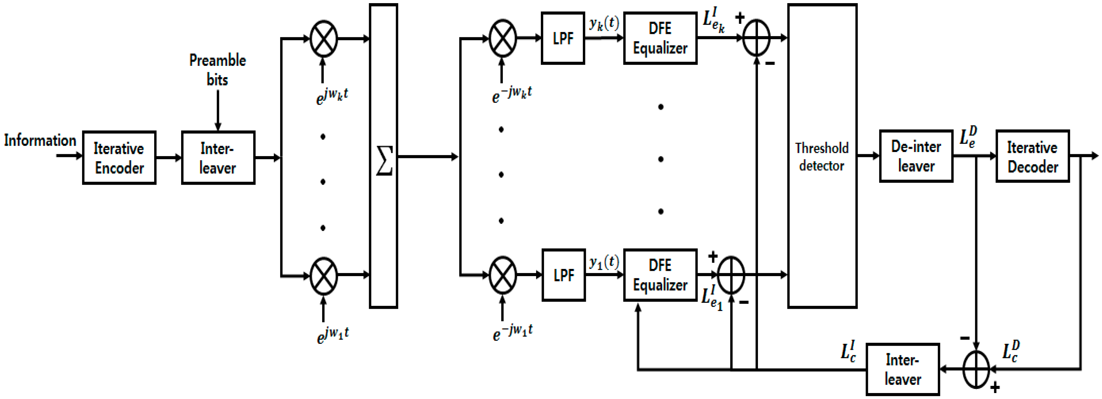
Based on the packet shown in Figure 1, the multi-band transceiver structure is modeled, as shown in Figure 2. After bits have passed through the channel coding at the transmission unit of Figure 2, coded bits are created. Signals that have passed through an iterative encoder and an interleaver, to change a burst error to a random error. After the interleaver, preamble bits, that is, are input for synchronous acquisition. The Data bit string with bits, which is configured by the input of , can be expressed by Equation (1).
Multi-band signal can be expressed by Equation (2).
The transmission signal is propagated, after different bands are multiplied by , is modulated for each band and the modulated signals for bands are added up.
The received signal is expressed by Equation (3).
represents the -th multi-path among the total multi-paths. represents the channel response coefficient in the path , and represents the Gaussian noise. The receiver signal is demodulated for different bands and the output signal of the -th band, which had passed through the LPF and the equalizer, was referred to as . Here, the input signal of the decoder can be expressed by Equation (4).
As for the signal received, a matched filter is used to divide each frequency and acquire the corresponding information. Then, a DFE (Decision Feedback Equalizer) removes the multi-path interference from each band and a threshold value is determined, by which the performance of the encoder is judged [16,17]. After the threshold detection, weighting factor, , for the -th band is assigned. In this manner, the data of a band, which comes close to the error decoding performance limit of the decoder, are decoded. The external input is the extrinsic information of the decoder. The estimated extrinsic information of at decoder output is given by
In the iterative turbo equalization method, equalizer and decoder are connected through the interleaving and de-interleaving functions that update each other’s information, recursively. The interleaved output is canceled, a posteriori, from the proceeding received signal. The interleaving helps the receiver convergence. Its extrinsic value calculates the post-probability which is error correction terms. The re-interleaving of the computed value, as , is added to the received signal of each band, and input to the DFE. is the correction factor in order to compensate for the errors. As the number of iteration of turbo equalization increases, the updated error correction approaches the original signal which is to be transmitted, thereby, improving the BER (Bit Error Ratio) performance [18,19].
2.2. Threshold Detection Algorithm
In some channel environments, a multi-band configuration shows a performance inferior to that of a single-band one. This is because the performance degradation in a particular band affects the output from all the bands, which is then input into an encoder, thereby, decreasing the overall performance. This problem can be solved by using a receiving end that analyzes the error rates of each band, sets the threshold values, and allocates the lower weights to the inferior bands.
There are two conventional methods of setting the threshold values [20,21]. The first is the ESNR (Effective Signal to Noise Ratio) estimation. This method uses a pilot signal or preamble data, which are already known between the receiving and transmitting ends, to estimate a receiving SNR. The relation between the estimated SNR (Signal to Noise Ratio) and the un-coded error rate of a channel coding/decoding algorithm is utilized to set a threshold value that satisfies the QEF (Quasi-Error-Free) condition of the channel-coding algorithm.
The second one is the PES (Post-Equalization SNR) estimation. Like the ESNR method, a threshold value is set which can satisfy the QEF condition of a channel-coding algorithm. To set such a threshold value, the PES method measures an error element (which is the difference of the output between an equalizer and a received signal) at the equalizer, which applies LMS (Least Mean Square) or RLS (Recursive Least Square) types to the receiving end [22,23]. However, since the threshold values, determined by this method, do not depend on noise power but on interference due to multi-path, they may be inaccurate in a real system with various multi-paths.
The threshold-setting algorithm, proposed in this study, utilizes the preamble data that are already known to both the transmitter and the receiver. This algorithm sets a threshold value by measuring the error rate of the preamble data and predicting the data performance, at the payload section. The conventional underwater communication methods use the preamble data as the training symbol of an equalizer, to remove the effects of multi-path and synchronous acquisition of frequency, and the phase of the payload. However, since the performance of payload data can also be predicted based on the error rate of the preamble data, information can be provided to the decoding unit of payload data. In a poor-channel environment like that of a multi-path, numerous preamble data are allocated, and the error rates of these data are also related to that of the payload. Accordingly, the error rate of the un-coded preamble is used to predict the error rate of the payload, and to set a threshold value that can satisfy the QEF condition, after decoding the payload.
3. Experimental Conditions and Parameters
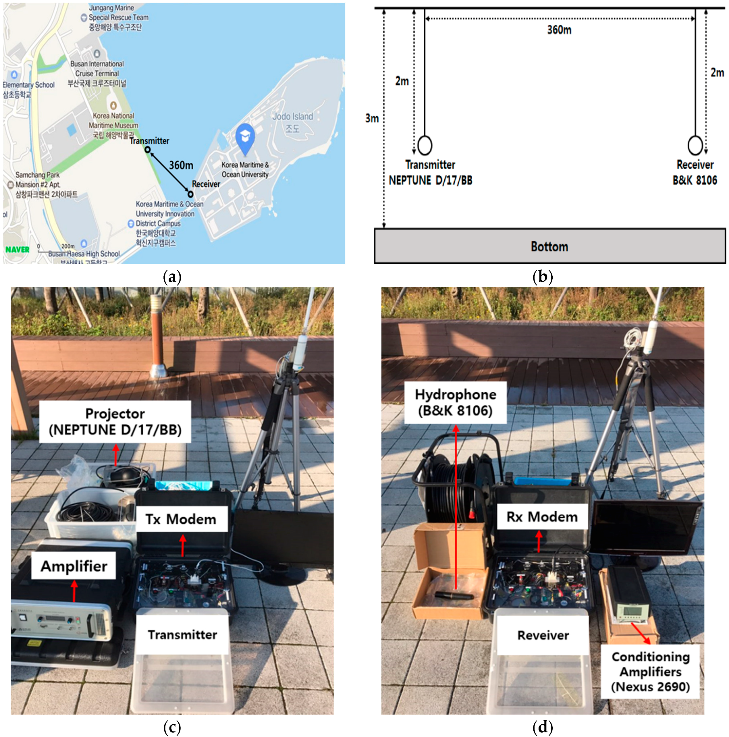
The actual underwater test was conducted in the same environment, as shown in Figure 3. The experiment was conducted, at sea, in front of the Korea Maritime and Ocean University, Korea, in March 2018, as shown in Figure 3a. The experimental setup schematic is shown in Figure 3b. The water depth was approximately 3 m. The hydrophone was at 2 m, below the water surface, and the horizontal range from the transmitter was 360 m. We used NEPTUNE D/17/BB transmitter and a B&K 8106 receiver. A photo of the measurement equipment-setup is shown in Figure 3c,d.
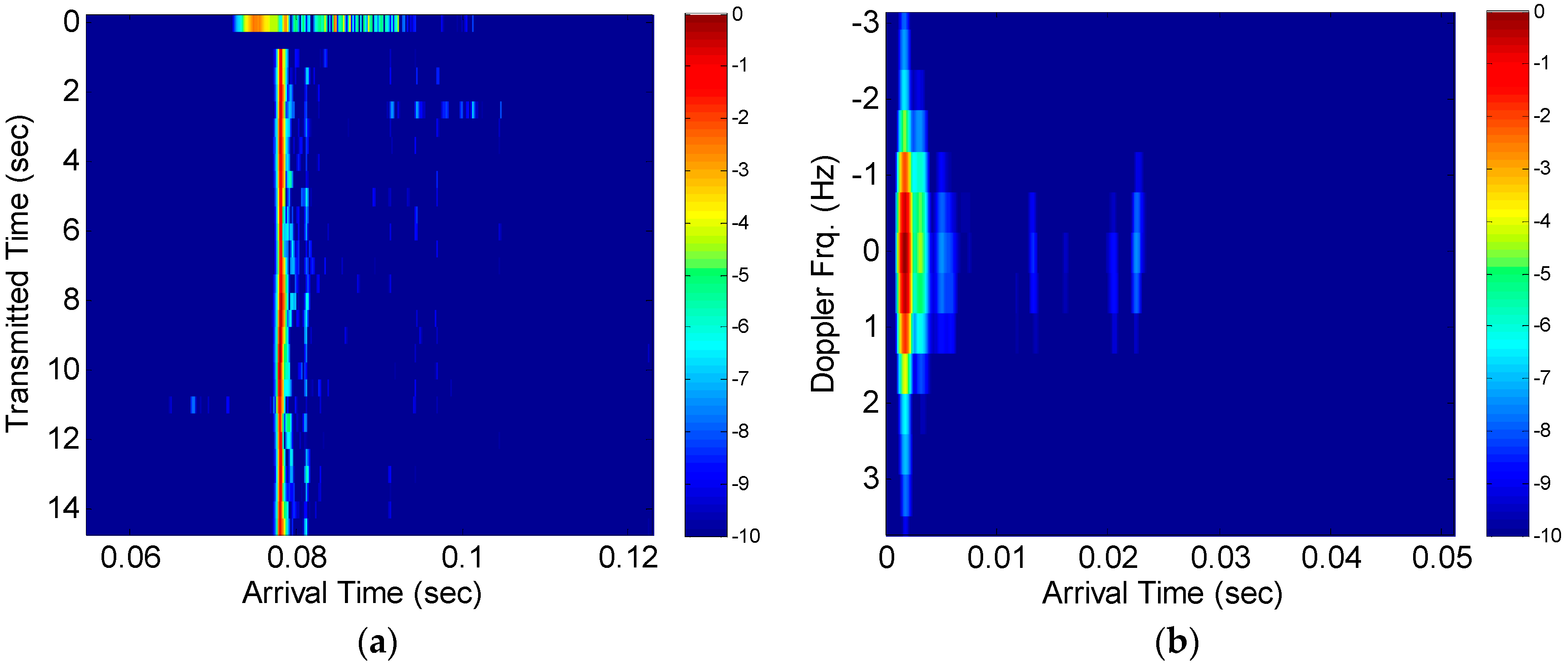
In Figure 4a, the UWAS channel response is shown during a 0.02 s interval. This response was measured by using an LFM (Linear Frequency Modulation) signal with a bandwidth of 2 kHz. The channel gains fluctuated for the secondary and third arrivals. This sparse channel was affected by a multi-path propagation, by reflection from the surface and the bottom. Figure 4b shows the Doppler-spreading for the different arrival times of the LFM signal; a tiny Doppler spreading in the range of −1 Hz to 1 Hz had occurred.
This study conducted an underwater experiment where the parameters shown in Table 1 were used to increase the number of bands.
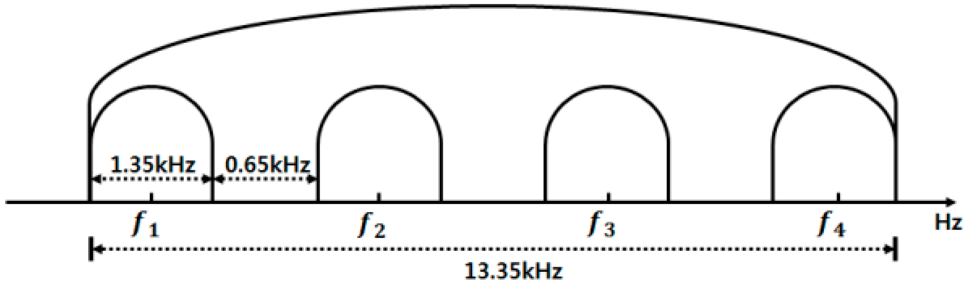
As presented in Table 1, there was a total of 592 bits, consisting of 256 preamble bits and 336 coded bits. QPSK (Quadrature Phase Shift Keying) modulation was applied to form 296 symbols. The SRRC (Square Root Raised Cosine) filter with the roll-off factor of 0.35 was applied as the filters of the receiving and the transmitting units. The inner iteration of the turbo decoder was five times. The total iteration between the turbo decoder and the DFE was six times. The transmission rate was 1 kbps. The center frequencies of each band were 12 kHz, 16 kHz, 20 kHz, and 24 kHz, respectively, and the sampling frequency was 192 kHz. When four multi-bands were used, the center frequency was allocated, as shown in Figure 5.
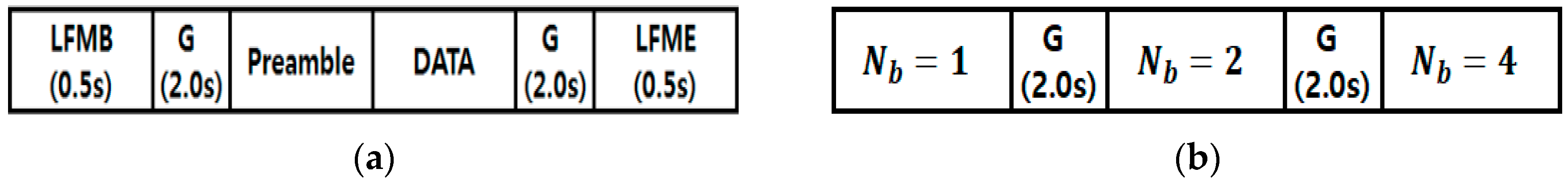
The transmission signal had a bandwidth of 1.35 kHz. To prevent the inference of adjacent bands, a guard band of 0.65 kHz was allocated between each band. When the four multi-bands were used, the total bandwidth was 13.35 kHz. Figure 6 illustrates the packet structure of the transmission signal.
Figure 6a shows the packet structures, inside each band. As is clear from Figure 6, a single packet was composed of LFMB (LFM Begin) signal, for notifying the beginning of transmission for 0.5 s, the silence section for 2 s, the preamble bit and the transmission data, another silence section for 2 s, and the final LFME (LFM End) signal, for notifying the end of the signal, for 0.5 s. Figure 6b presents the packet structure of the transmission signal in the case of . The packet structure of each of the bands, shown in Figure 6a, was located at , , , in Figure 6b. The silence section for 2 s was applied between each band to form the packet structure of a multi-band transmission signal. The silence was designed to be long enough to avoid the inter-packet interference during the transmission of data. The preamble data were used to achieve the accurate synchronous acquisition of received signals and to estimate the multi-paths, in a DFE.
4. Experimental Result
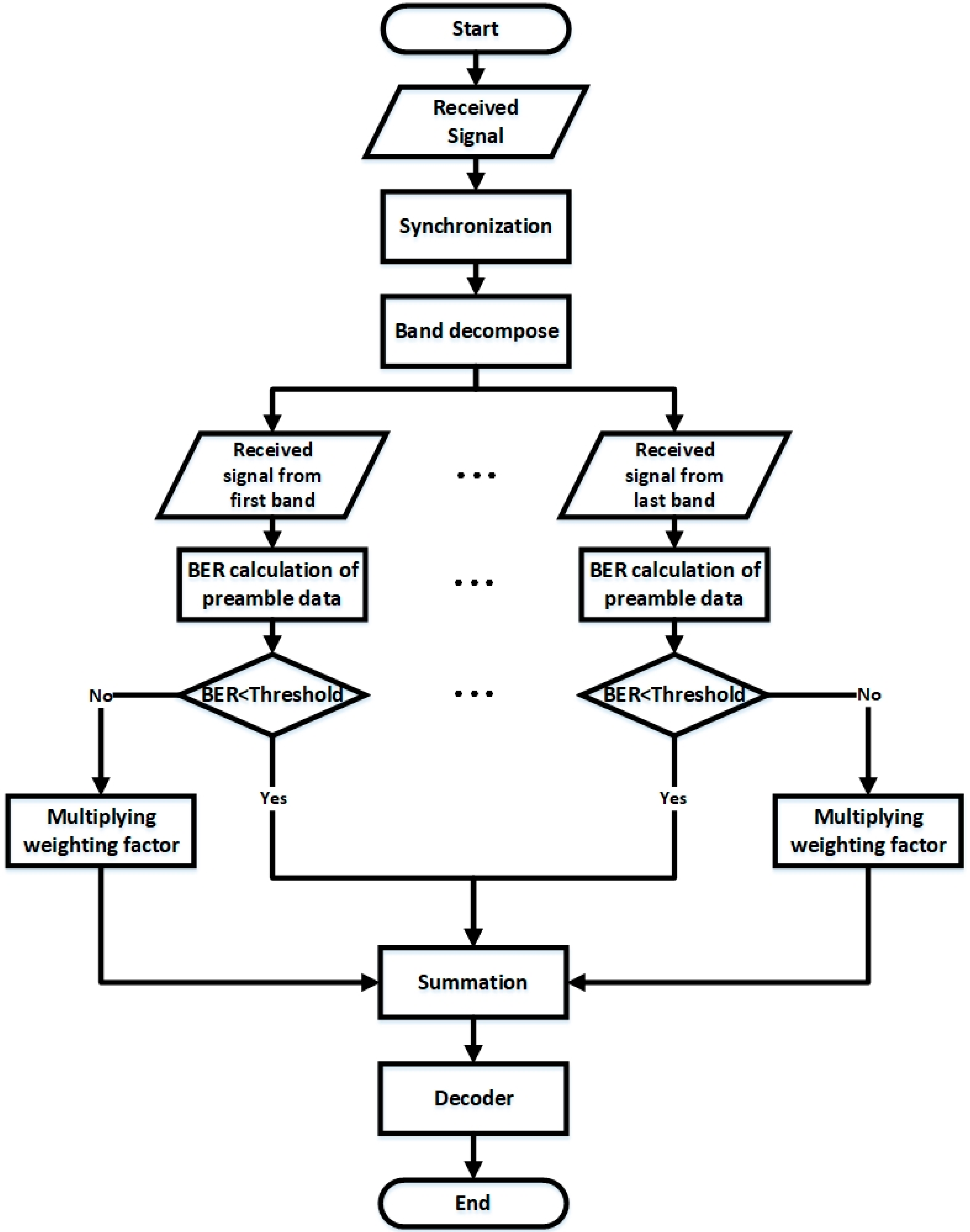
To prove the efficiency of the proposed algorithm, a flowchart of the performance evaluation has been depicted in Figure 7.
After receiving the distorted signals induced by Doppler, multi-paths, and other factors, multi-band signals were divided into a single band of , by a band-pass filter number. Synchronizations including Doppler and phase compensation were performed, based on the preamble data which were known to the transmitter and the receiver. It also acquired the beginning of data fields. After synchronization, we calculated the BER of each band, using the compensated preamble data. To apply the proposed threshold algorithm, if the calculated BER of each band was lower than the threshold, the demodulated data of that band was passed to the summation block, else, it was multiplied by the weighting factor and passed on to the summation block.
Based on Figure 7, the underwater experiment was performed by using the packet structure of Figure 6b. Table 2 presents the average error rates of data that were transmitted, repetitively, for five times.
As shown in Table 2, when the number of bands increased from 1 to 4, the performance improved. When four multi-bands were used and the total iteration number of 6 was applied between the equalizer and the decoder, all of the data were decoded without error. The error rates of preamble data used in each band were analyzed. It turned out that, when the number of bands increased, the error rate of the preamble had both improved and degraded. The four multi-band worsened the error rate of preamble data of band. We have tried to re-transmit these same, four, multi-band signals, after several minutes (denotes 4*). The performance was worse than the single and double band ones, in this case, because the performance in one particular band affected the output from the entire range of bands. To improve the performance, the proposed threshold-setting algorithm was applied based on the preamble error rates. Table 3 presents the results of this application.
In order to improve the BER performance, it was very important to decide the weighting value for each frequency band. The relationship between the BER of the un-coded preamble sequence and that of the coded data field depended on what kind of coding methods and coding rates were used. Generally, BER of un-coded preamble sequence had under a 10−1, BER of the coded data field with a guarantee for the QEF region, in the case of turbo pi codes with rates of 1/3. In the case of = 4 and = 4*, different weighting values were applied, for each specific frequency band. In order to find the optimal weighting value for each frequency band, based on their relationship, we assigned different weighting values to each frequency band, in the range of 0.1 to 1. Since the four bands ( = 4) showed poor error rates for the preamble data of band, the threshold value of the data was set to 0.1 to minimize the impact on the entire data. Consequently, when the total iteration number of turbo equalization was 1, all of the data could be decoded without error. Similar to that of = 4*, when the total iteration number of turbo equalization was 2, all of the data could be decoded without error.
5. Conclusions
For improving the performance in UWAS communications, multi-band techniques, and turbo equalization models have been used, in recent years. The multi-band communication technology is effective in performance and processing efficiency because it can overcome selective frequency fading, by allocating the same data to different frequency bands, in an environment that has a rapidly changing UWA channel transmission characteristic. In others, at the receiver side, we resorted to powerful turbo equalization algorithms that iteratively exchanged probabilistic information between the DFE and the turbo decoder, thereby, reducing the error rates significantly. We have analyzed the efficiency of multi-band transmission schemes in the UWAS communication, by applying 1~4 number of multi-bands, using a turbo pi code with a coding rate of 1/3. This was carried out in an actual underwater experiment which was conducted at the sea, in front of the Korea Maritime and Ocean University, Korea, in March 2018. Experimental results showed that, in general, the performance increased as the number of multiple bands and iterations of turbo equalization increased. However, a multi-band configuration can have poorer performance than a single-band, or double-band configuration. This problem could be solved by using a receiving end that analyzed the error rates of each band, set the threshold values, and allocated the lower weights to the inferior bands. In this paper, we proposed an algorithm to set the threshold value using the preamble error rate which was known data that had to be transmitted and received, based on the relationship between the BER of un-coded preamble sequence and the coded data field. We confirmed that when the total iteration number of turbo equalization was 1 or 2, all of the data could be decoded without any error. Based on the experimental results, multi-bands with a weighted turbo-equalized algorithm is a useful technology for performance enhancement, in the environment of UWAS communications.
For future studies, based on the proposed algorithm, we will apply it to the multicarrier OFDM system to compensate for the multi-path effect and increase the throughput. Finally, it will be applied to long-range UWAS communications that will further increase the distance between the transceivers.
Author Contributions
Conceived and designed the experiment, H.-S.L., C.-U.B. and J.-W.J.; Analyzed the experimental data, H.-S.L., C.-U.B. and W.-J.K.; Wrote the paper, H.-S.L.; Revised the paper and offered useful suggestion to write, C.-U.B., and J.-W.J.
Funding
This research was funded by the Agency for Defense Development grant number [UD170022DD].
Conflicts of Interest
The authors declare no conflicts of interest.
References
- Stojanovic, M.; Beaujean, P.-P.J. Acoustic Communication. In Springer Handbook of Ocean Engineering; Dhanak, M.R., Xiros, N.I., Eds.; Springer International Publishing: Berlin, Germany, 2016; pp. 359–386. [Google Scholar]
- Jiang, R.; Cao, S.; Xue, C.; Tang, L. Modeling and analyzing of underwater acoustic channels with curvilinear boundaries in Shallow Ocean. In Proceedings of the 2017 IEEE International Conference on Signal Processing Communications and Computing (ICSPCC), Xiamen, China, 22–25 October 2017; pp. 1–6. [Google Scholar] [CrossRef]
- Zhang, X.; Cui, J.H.; Das, S.; Gerla, M.; Chitre, M. Underwater wireless communications and networks: Theory and application: Part 1 [Guest Editorial]. IEEE Commun. Mag. 2015, 53, 40–41. [Google Scholar] [CrossRef]
- Kilfoyle, D.B.; Baggeroer, A.B. The state of the art in underwater acoustic telemetry. IEEE J. Ocean. Eng. 2000, 25, 4–27. [Google Scholar] [CrossRef]
- Diamant, R.; Lampe, L. Adaptive error-correction coding scheme for underwater acoustic communication networks. IEEE J. Ocean. Eng. 2015, 40, 104–114. [Google Scholar] [CrossRef]
- He, Q.; Wang, S.; Zhang, W. Low-complexity MMSE iterative equalization for multiband OFDM systems in underwater acoustic channels. In Proceedings of the 2017 IEEE International Conference on Communication Software and Networks (ICCSN), Guangzhou, China, 6–8 May 2017; pp. 492–497. [Google Scholar] [CrossRef]
- Wang, Y.; Zeng, Z.; Li, Y.; Zhang, J.; Jin, S. Multicarrier spread spectrum communication scheme for cruising sensor network in confined underwater space. Int. J. Distrib. Sens. Netw. 2014, 10, 165749. [Google Scholar] [CrossRef]
- Esmaiel, H.; Jiang, D. Review Article: Multicarrier Communication for Underwater Acoustic Channel. Int. J. Commun. Netw. Syst. Sci. 2013, 6, 361–376. [Google Scholar] [CrossRef]
- Zhou, Y.; Song, A.; Tong, F.; Kastner, R. Distributed compressed sensing based channel estimation for underwater acoustic multiband transmissions. J. Acoust. Soc. Am. 2018, 143, 3985–3996. [Google Scholar] [CrossRef] [PubMed]
- Qu, F.; Wang, Z.; Yang, L.; Wu, Z. A journey toward modeling and resolving doppler in underwater acoustic communications. IEEE Commun. Mag. 2016, 54, 49–55. [Google Scholar] [CrossRef]
- Yang, Z.; Zheng, Y.R. Iterative channel estimation and turbo equalization for multiple-input multiple-output underwater acoustic communications. IEEE J. Ocean. Eng. 2016, 41, 232–242. [Google Scholar] [CrossRef]
- Van Walree, P.A.; Leus, G. Robust Underwater Telemetry with Adaptive Turbo Multiband Equalization. IEEE J. Ocean. Eng. 2009, 34, 645–655. [Google Scholar] [CrossRef]
- Vasudevan, K. Digital Communications and Signal. Processing, 3rd ed.; Universities Press: Hyderabad, India, 2017; pp. 1–461. [Google Scholar]
- Ďurček, V.; Michal, K.; Milan, D. Turbo-principle-based decoding in LDPC and turbo codes. Carpath. J. Electron. Comput. Eng. 2017, 10, 21–25. [Google Scholar]
- Douillard, C.; Berrou, C. Turbo Code with Rate-m/(m+1) Constituent Convolutional Codes. IEEE Trans. Commun. 2005, 53, 1630–1638. [Google Scholar] [CrossRef]
- Salz, J. Optimum mean-square decision feedback equalization. Bell Syst. Tech. J. 1973, 52, 1341–1373. [Google Scholar] [CrossRef]
- He, C.; Jing, L.; Xi, R.; Li, Q.; Zhang, Q. Improving Passive Time Reversal Underwater Acoustic Communications Using Subarray Processing. Sensors 2017, 17, 937. [Google Scholar] [CrossRef]
- Baek, C.U.; Jung, J.W. High throughput receiver structure for underwater communication. Int. J. Distrib. Sens. Netw. 2015, 11, 481576. [Google Scholar] [CrossRef]
- Zheng, Y.R.; Wu, J.; Xiao, C. Turbo equalization for single-carrier underwater acoustic communications. IEEE Commun. Mag. 2015, 53, 79–87. [Google Scholar] [CrossRef]
- Wan, L.; Zhou, H.; Xu, X.; Huang, Y.; Zhou, S.; Shi, Z.; Cui, J.H. Adaptive Modulation and Coding for Underwater Acoustic OFDM. IEEE J. Ocean. Eng. 2015, 40, 327–336. [Google Scholar] [CrossRef]
- Baek, C.U.; Jung, J.W.; Do, D.W. Study on the Structure of an Efficient Receiver for Covert Underwater Communication Using Direct Sequence Spread Spectrum. Appl. Sci. 2018, 8, 58. [Google Scholar] [CrossRef]
- Ayvaz, E.N.; Meryem, M.; Ali, Ö. A fast start-up modified LMS algorithm. In Proceedings of the 2018 26th Signal Processing and Communications Applications Conference (SIU), Izmir, Turkey, 2–5 May 2018; pp. 1–4. [Google Scholar] [CrossRef]
- Djigan, V.I.; Shakhtarin, B.I.; Likhoedenko, K.P.; Zhurakovskiy, V.N. Multichannel stabilized fast RLS algorithm for nonstationary signal processing. In Proceedings of the 2017 IEEE East-West Design & Test Symposium (EWDTS), Novi Sad, Serbia, 27 September–2 October 2017; pp. 1–7. [Google Scholar] [CrossRef]
Figure 1.
Packet structure for multi-band transmission.

Figure 2.
Transceiver structure of multi-band communications.

Figure 3.
Illustration of the sea trial: (a) Area map of the sea trials, (b) experimental setup schematic, (c) transmission equipment, (d) receiver equipment.
Figure 3.
Illustration of the sea trial: (a) Area map of the sea trials, (b) experimental setup schematic, (c) transmission equipment, (d) receiver equipment.

Figure 4.
Underwater experimental environment: (a) CIR (Channel Impulse Response); (b) scattering function.
Figure 4.
Underwater experimental environment: (a) CIR (Channel Impulse Response); (b) scattering function.

Figure 5.
Frequency division.

Figure 6.
Transmission signal packet structure: (a) Individual band packet structure; (b) multi-band packet structure.
Figure 6.
Transmission signal packet structure: (a) Individual band packet structure; (b) multi-band packet structure.

Figure 7.
Flowchart for the performance evaluation procedure.


Table 1.
Experimental parameters.
| Source | 112 bits |
| Preamble bit | 256 bits |
| Number of inner iteration (Turbo decoder internal iteration) | 5 |
| Number of total iteration (Iteration between turbo decoder and DFE) | 6 |
| Channel coding | Turbo Pi code |
| Coding rate | 1/3 |
| Modulation | QPSK |
| Packet size | 296 symbols |
| Equalizer | LMS DFE |
| Number of bands () | 1~4 |
| Center Frequency of each Band | = 12 kHz = 16 kHz = 20 kHz = 24 kHz |
| Number of samples () | 384 |
| Sampling frequency | 192 kHz |
| Bit rate | 1 kbps |
| Distance | 360 m |
| Water depth | 3 m |
| Depth | Transmitter: 2 m, Receiver: 2 m |
Table 2.
The Bit Error Ratio (BER) performance of Experimental results.
| Preamble BER | Number of Iterations of Turbo Equalization | |||||||
|---|---|---|---|---|---|---|---|---|
| 1 | 2 | 3 | 4 | 5 | 6 | |||
| 1 | ||||||||
| 2 | ||||||||
| 4 | 0 | |||||||
| 4* | ||||||||
Table 3.
Experimental results for preamble error rate-based threshold-setting algorithm.
| Preamble BER | Weighting | Total Number of Iterations | |||||||
|---|---|---|---|---|---|---|---|---|---|
| 1 | 2 | 3 | 4 | 5 | 6 | ||||
| 4 | 0 | 0 | 0 | 0 | 0 | 0 | |||
| 4* | 0 | 0 | 0 | 0 | 0 | ||||
© 2018 by the authors. Licensee MDPI, Basel, Switzerland. This article is an open access article distributed under the terms and conditions of the Creative Commons Attribution (CC BY) license (http://creativecommons.org/licenses/by/4.0/).
Share and Cite
MDPI and ACS Style
Lee, H.-S.; Baek, C.-U.; Jung, J.-W.; Kim, W.-J. A Weighted Turbo Equalized Multi-Band Underwater Wireless Acoustic Communications. Appl. Sci. 2018, 8, 1711. https://doi.org/10.3390/app8101711
AMA Style
Lee H-S, Baek C-U, Jung J-W, Kim W-J. A Weighted Turbo Equalized Multi-Band Underwater Wireless Acoustic Communications. Applied Sciences. 2018; 8(10):1711. https://doi.org/10.3390/app8101711
Chicago/Turabian StyleLee, Hui-Su, Chang-Uk Baek, Ji-Won Jung, and Wan-Jin Kim. 2018. "A Weighted Turbo Equalized Multi-Band Underwater Wireless Acoustic Communications" Applied Sciences 8, no. 10: 1711. https://doi.org/10.3390/app8101711
Note that from the first issue of 2016, this journal uses article numbers instead of page numbers. See further details here.