Abstract
In this work, a vibro-acoustic numerical and experimental analysis was carried out for the chain cover of a low powered four-cylinder four-stroke diesel engine, belonging to the FPT (FCA Power Train) family called SDE (Small Diesel Engine). By applying a methodology used in the acoustic optimization of new FPT engine components, firstly a finite element model (FEM) of the engine was defined, then a vibration analysis was performed for the whole engine (modal analysis), and finally a forced response analysis was developed for the only chain cover (separated from the overall engine). The boundary conditions applied to the chain cover were the accelerations experimentally measured by accelerometers located at the points of connection among chain cover, head cover, and crankcase. Subsequently, a boundary element (BE) model of the only chain cover was realized to determine the chain cover noise emission, starting from the previously calculated structural vibrations. The numerical vibro-acoustic outcomes were compared with those experimentally observed, obtaining a good correlation. All the information thus obtained allowed the identification of those critical areas, in terms of noise generation, in which to undertake necessary improvements.
1. Introduction
The new more stringent environmental laws in the automotive industry induced original equipment manufacturers (OEMs) and their suppliers and partners to address their efforts towards eco-friendly vehicle development, keeping low noise emissions and high passenger comfort levels. This is because—especially for premium cars—the interior acoustics play an important role for the drive comfort and drivers’ subjective perception of quality, which in turn influences the customer’s satisfaction and furthermore the purchase decision.
Currently, research and development is focusing strongly on multi-material applications for lightweight bodies by combining aluminum, magnesium, high-strength steels, Carbon Fiber Reinforced Polymer (CFRP), and organic sheets. Such materials will help to meet future requirements for lower weight, higher safety, and increased strength. However, lightweight materials are easily activated from a vibrational point of view (lightweight structures exhibit lower mass damping effects on vibrations), making them noisier. In order to design an improved lightweight vehicle body with suitable vibration and acoustics properties, the structural dynamics, vibrating behavior, sound transmission, and radiating performances must be examined in detail (e.g., some aspects of the plastic timing chain cover performances are presented in [1]). With reference to the powertrain, a reduction of noise emission can be obtained by optimizing cover structures (e.g., stiffening them or adding damping material).
Besides combustion noise, the noise generated by mechanical contacts of the moving and vibrating parts in an engine contributes to the overall engine noise. Depending on the engine operating condition, this mechanical noise may become the dominant part [2].
In order to improve the lifetime and reliability performances of the timing drive systems used in the automotive industry, the engines are often equipped with chain drives that become—with their vibrations—possible sources of disturbing noise. An early assessment of possible negative acoustical effects of the chain drive by the excitation of surrounding structures can significantly reduce the costs for prototyping and successive changes in the layout of the chain drive and engine.
The main inner excitation mechanism in the chain drive is the polygonal action, which means that a chain engaging on a sprocket forms a polygon rather than a circle due to the discretization of the sprocket teeth which couples with chain rollers. Since the polygonal effect occurs with the meshing frequency, the excited vibrations are basically narrow-banded and can finally be evaluated as an annoying whine-noise (the typical noise excited by polygonal chain drive action is named chain whine or meshing noise). The so-called polygon frequency depends on the number of teeth and the rotational speed of the sprocket. In general, the polygon frequency lies between some 100 and some 1000 Hz [3].
Commonly, only a few elastic structures (e.g., shafts) are considered in dynamic chain drive simulations. To consider the fully elastic behavior of arbitrary complex structures of chain drive components and the surrounding structure, a possible approach combines the multibody representation of the chain with an elastic Finite Element (FE) structure [4,5].
The main parameters that influence the system behavior and hence the acoustic performance of the model are:
- stiffness and damping of chain, guides, shafts/sprockets, bearings, and surrounding structure;
- inertias of chain, sprockets, plunger (tensioner), and tensioning guide;
- friction between chain–sprocket, chain–guides, chain link–sprocket;
- behavior of tensioner: damping (leakage, ventilation), and stiffness (oil, spring).
Another problem of the timing system equipped with chain is the elongation due to wear, responsible for an increase of noise due to impact and vibrations.
An integrated experimental and analytical modeling approach aimed at examining the impact noise characteristics of automotive-type timing chain drive systems was presented in [6], where a comparative study between various system parameters and operating conditions was provided.
An acoustic model relating the dynamic response of rollers and corresponding induced sound pressure levels is developed in [7], where the acceleration response of each chain roller for the noise level prediction of a chain drive under varying operating conditions was studied by a FEM (finite element method) approach.
Timing chain systems were modeled in [8] by a theoretical approach considering mass viscoelastic contact characteristics of each link or tooth separately.
A new roller chain sprocket tooth geometry for engine camshaft drives was studied in [9], having as a target the reduction of noise levels during meshing. Experimental tests were carried out to compare the noise levels of the asymmetrical sprocket tooth profile to that of a standard ISO sprocket tooth profile.
Experimental studies of timing chain vibration aimed at avoiding acoustically critical excitations were carried out in [10].
The modeling of the entire timing drive system containing a bushing chain drive, camshafts, and all connected single valve train was presented in [11], where the primary dynamics of the chain drive and the forces which are transferred to the engine’s structure were assessed.
The torsional oscillations of engine camshafts induced by valve train loads were studied in [12]: they can cause significant tension fluctuation in the timing chain with corresponding increase in the chain transverse vibrations; this in turn causes an undesirable impact noise from the chain or sprocket meshing process.
In this work, the use of acoustic boundary elements and structural finite elements is aimed at the prediction of the radiation of structural noise from a side cover. A comparison is made between numerical results and experimental measurements, and a discussion is provided for the practical application of these modeling methods to side cover design. As a matter of fact, a computational method to allow reproducing the actual performance of a component for a car engine from a vibro-acoustic point of view was developed.
The vibro-acoustic numerical and experimental analysis was carried out for the chain cover of a low-powered four-cylinder four-stroke diesel engine (Figure 1a), belonging to the FPT (Fiat Power Train) family called SDE (Small Diesel Engine).
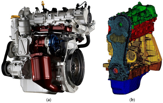
Figure 1.
(a) Fiat Power Train (FPT) Small Diesel Engine (SDE); (b) Finite element model (FEM) model of the engine.
By applying a methodology used in the acoustic optimization of new FPT engine components, firstly an FEM approach was applied for a modal analysis of the overall engine and also for a forced response analysis of the only chain cover. For the latter, the applied boundary conditions were the accelerations experimentally measured by accelerometers located at the points of connection among chain cover, head cover, and crankcase. Subsequently, a boundary element model of the only chain cover was realized to determine the chain cover noise emission, starting from the previously calculated vibrations [13]. The numerical vibro-acoustic outcomes were compared with those experimentally observed.
All the information thus obtained allowed the identification of those critical areas—in terms of noise generation—on which to undertake necessary improvements.
The modelling and computation were carried out with the support of the Hypermesh [14] and Abaqus [15] codes for the FEM modelling and modal analysis, and SIEMENS-LMS/Virtual Lab [16] for the BEM (boundary element method) modelling and vibro-acoustic analysis. In particular, Hypermesh code was used for the FEM mesh generation. The aforementioned software suites were selected being those in use in FPT at the time the work was performed.
2. Description of the Methodology
A vibro-acoustic analysis for a chain cover of a four-stroke four-cylinder diesel engine was performed through an FEM–BEM coupled approach. Such a hybrid approach—selected as an alternative to an FEM–FEM approach—is particularly advantageous when considering a free field acoustic emission, because with BEM it suffices to model the vibrating finite boundary, being null the contribution of integrals evaluated on the infinite boundary (Sommerfeld condition). Moreover, even for closed-domain acoustic emission problems, there can be computational advantages by coupling FEM and BEM approaches [17].
In [17], the reader can find detailed explanations about the way in which the interface between FEM and BEM approaches is realized (e.g., with reference to mapping of results from the FE-mesh to the BE-mesh with corresponding interpolation errors caused by such a data transfer process).
The vibration analysis is executed using FEM, whereas BEM is adopted for the simulation of the free field acoustic emission because it is more computationally efficient than FEM (BEM does not need to model the remote boundary at infinity as provided by the Sommerfeld radiation condition). A free field FE-based acoustic simulation would also be possible, but special FEM elements (infinite finite elements) would be necessary in this case.
The interface between the programs is realized by automatic data exchange tools available in the Virtual Lab environment following a theoretical approach detailed in [17] and synthetically reported in Section 4.
The BE approach combined with the acoustic transfer vector (ATV) technique in principle allows the acoustic emission to be evaluated in a shorter computational time when considering different engine regimes and various stiffening configurations.
Having to map a vibrational scenario from a refined FEM mesh to a coarse BEM mesh, some minor interpolation errors are introduced by the interfacing process.
Components showing a direct structural interaction with the chain cover were explicitly included in the FEM model: tappet cover, head, crankcase, sub-crankcase with bearing caps, and oil pan.
The FEM overall model (Figure 1b) consisted of 546,155 linear elements with a size of 6 mm and 507,978 nodes, whereas the chain cover was modelled by using quadratic elements with a size of 3 mm.
The overall FEM engine model is only adopted for a free-free modal analysis from which to extract the chain cover modal basis.
The modal analysis basis of the chain cover was extracted, leveraging on the results provided by the modal analysis of the overall engine. Afterwards, applying the vibrational excitations experimentally measured at the bolted connections between the chain cover and the engine block, a modal-based forced response analysis was performed for the chain cover.
The interface between chain cover and engine block was modelled using tie constraints everywhere except for the connection bolts where rigid elements (RBE2) are used. Equipment for the experimental vibrational measurements was available and consequently exploited to get a realistic assessment of the vibrational input to the chain cover.
The vibration numerical results were compared with corresponding experimental measurements.
The BEM model (Figure 2) was based on a discretization involving the component surface (outer “skin” of the component) and consisted of 1300 surface linear elements and 1385 nodes.
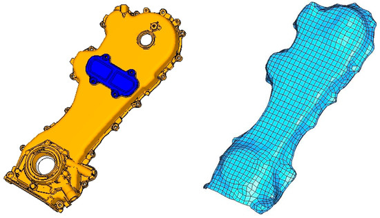
Figure 2.
Boundary element method (BEM) model of the chain cover.
The objective of this work was the evaluation of noise emission from the sole chain cover: in this respect, the BEM discretization was only applied to the component under examination.
The environmental acoustic pressure distribution was calculated by the BEM model, and then compared with the related experimental acquisitions.
3. Acoustic Analysis
A BEM analysis was carried out to provide the acoustic emission of the chain cover. It is important to underline that the acoustic calculation evaluates the noise emission solely due to structurally transmitted excitation vibrations (structural born noise). The airborne noise and that emitted by other sources is not taken into account in any way.
The BEM analysis was performed, resorting to the indirect BEM [18] (quantities at the surface are jump of pressure and jump of normal velocity) with a variational approach for the numerical resolution [19,20].
The acoustic calculation is performed on a modal basis and involves different stages [17]:
- creation of a BEM mesh;
- calculation of the ATVs;
- introduction of experimentally-measured vibration velocities on the BEM mesh;
- calculation of the sound pressure and sound power.
As mentioned, the BEM mesh represents the mesh of the component surface.
The ATVs [21] are transfer functions allowing the calculation of the sound pressure in the chain cover surrounding environment, starting from the structure vibration.
The ATVs depend on the geometry and impedance of the vibrating surface, the microphones position, the frequency, and the physical properties of the domain in which the sound propagates (temperature and density).
The calculation of the ATVs is independent from the vibration result, and consequently, it does not depend on the loading conditions and damping values used in the structural calculation.
If the vibrating surface is divided into a discrete number of elements, the relationship between their normal velocities and the sound pressure in multiple domain points can be expressed as follows:
where is the column vector containing the acoustic pressure in the different points of interest, is the transfer vectors matrix, and is the column vector containing the normal velocities of vibrating elements (as obtained by experimental measurements).
In particular, ATV is the output of a BEM problem solution, and represents the transfer function relating the vibration velocity in a node of the structure to the sound measured in a point of the acoustic domain.
The aforementioned computational processes represent a quite easy tool for the acoustic calculation. In fact, once the mesh of the component has been defined, it turns to the ATVs computation.
The ATVs’ independence from the structural modal response entails a remarkable advantage in terms of computational times reduction, since any further modification to the component—which does not require a variation of its outer surface (acoustic emission side)—can be processed without the need for an ex-novo ATVs computation.
ATVs would only change if the external (emission side) chain cover design changed, whereas they would not be affected by structural changes on the remaining part of engine or changes in the excitations.
The main interest of this work stands in the assessment of chain cover emission in order to optimize its shape. The idea is to apply ribs on the chain cover internal side in order to stiffen it and correspondingly reduce the acoustic emission versus variable engine regimes.
The boundaries of the BE model enclose a domain; to avoid the presence of anomalous peaks in correspondence of the eigenfrequencies of such enclosed acoustic cavity, a specific impedance was assigned to the internal surface of the elements (and therefore to the material), equal to that of air—that is, 416.5 Rayl (kg∙s−1∙m−2).
Having placed the microphone in the chain cover near field, it is reasonable to assume that the contribution from parts other than the chain cover to the recorded sound pressure level turns out to be negligible.
4. Experimental Data
The vibrations transmitted by the engine running at 850 rpm were measured by placing 17 unidirectional accelerometers in correspondence with the attachment points of the chain cover to the rest of the engine (Figure 3), and placing a unidirectional accelerometer (for this kind of application, piezoelectric accelerometers perform pretty well) on top of the cover (Figure 4). Moreover, a microphone was placed in proximity of the cover (near-field microphone) (Figure 5). A microphone array was avoided because, due to its extension, it would be sensible to noise coming from parts other than the chain cover.
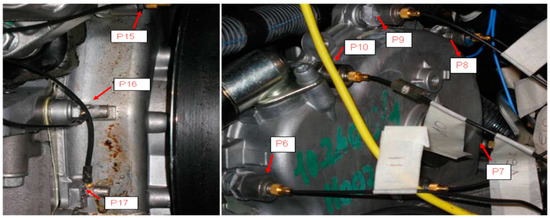
Figure 3.
Accelerometers placed in proximity to the connecting pins between the chain cover and the rest of the engine.
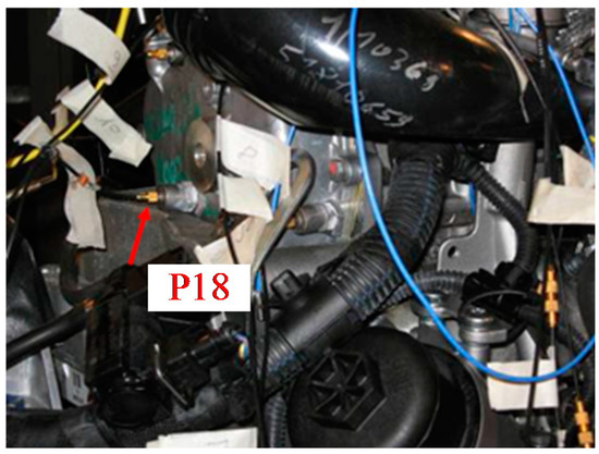
Figure 4.
Accelerometer placed on the chain cover.
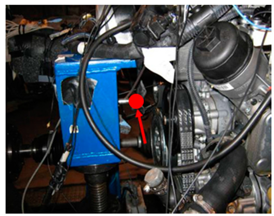
Figure 5.
Near-field microphone.
The standard ISO 3745 recommends the use of one microphone at the distribution side, one at the exhaust, one at the inlet, one for the timing of valves, and another one for gears. Being only interested in the (near-field) distribution emission, only the corresponding microphone was arranged.
The accelerometers placed on the fasteners detect the excitations acting on the cover in terms of local imposed accelerations; the latter are subsequently integrated by the code for vibro-acoustic assessment in order to obtain a profile of vibrational velocities (boundary conditions for the acoustic analysis). The accelerometer placed on the cover surface detects the vibration response of the chain cover, to be compared with the numerical vibration response. The near-field microphone—due to its short distance from the cover—essentially measures the sound pressure generated by the cover vibration phenomenon.
5. Vibro-Acoustic Validation
The experimental data allow the values of the excitation input for the BEM computational model to be obtained, to be introduced in the form of velocities at the attachment points of the chain cover (Figure 6).
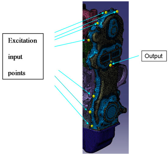
Figure 6.
Vibro-acoustic model for the vibration analysis.
In the model for the numerical vibration analysis, 17 nodes in which the measured accelerations are converted into velocities were inserted at the attachment points between the cover and the engine. Moreover, in addition to the selected position for the accelerometer placed on the chain cover, also a node constituting the point in which the forced response is detected is taken into consideration (Figure 6).
The code for vibro-acoustic assessment allows the determination of the forced vibration response of the narrow-band model in the frequency range 1–4000 Hz (this is the frequency range of interest).
The relevant modes of the chain cover are in the range 1–3 kHz, and the excitation is mainly related to the engine regime that is generally lower than 4 kHz (e.g., the relevant combustion frequencies are much lower, being in a range lower than 200 Hz). Consequently, there is no interest to go further with the maximum frequency of considered eigenmodes. On the other hand, a further acoustic and structural mesh refinement would be needed to operate at higher frequencies.
It can be observed how the behavior of the numerical and experimental curves are consistent with each other (Figure 7).
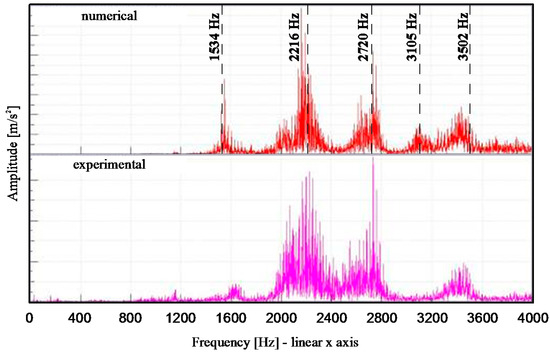
Figure 7.
Narrow-band numerical (up) and experimental (down) comparison of the acceleration at the measurement point.
For the numerical acoustic analysis, a virtual microphone was placed in the position where the experimental outcomes are measured (Figure 8). The narrow-band sound pressure in the range 1–4000 Hz was first obtained, and then compared with data experimentally acquired, showing a satisfactory correlation (Figure 9).
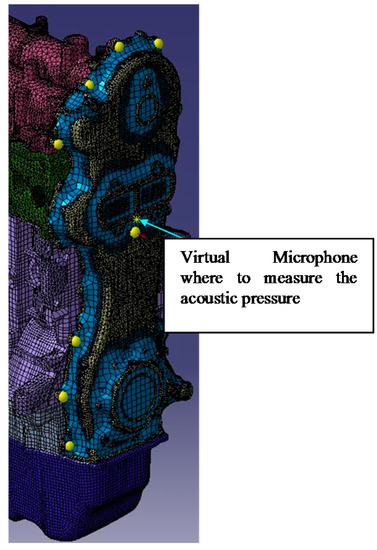
Figure 8.
Vibro-acoustic model for the acoustic analysis.
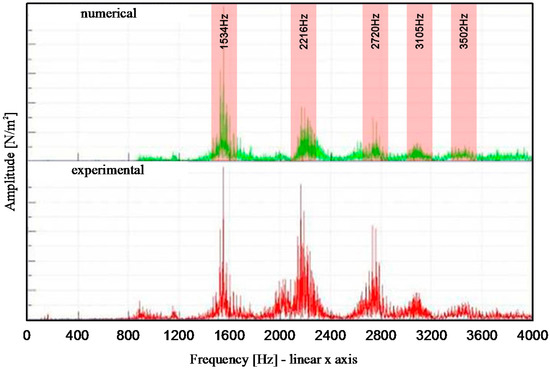
Figure 9.
Narrow-band numerical (up) and experimental (down) comparison of the sound pressure magnitude.
The dominant frequency of 3200 Hz is missing in the numerical result: one possible reason could be related to the approximation inherent to the assumption of a uniform modal damping (3–5%) in the whole frequency range.
The results related to the sound pressure allowed the resonant frequencies to be identified, and therefore the corresponding resonant modes for which the noise emission of the chain cover is maximum (Figure 9).
Once the resonant frequencies and modes are known (Table 1), for each mode, the areas of the cover exhibiting higher emissions are visible (Figure 10).

Table 1.
Critical modes.
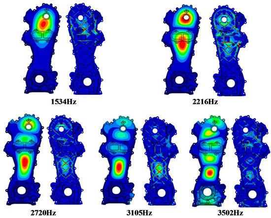
Figure 10.
Chain cover eigenmodes.
The obtained information can be used during the component design/development phase, in order to reduce its noise emissions.
6. Conclusions
In this work, a computational model for the vibro-acoustic analysis of the chain cover of a car diesel engine was developed.
The numerical results were compared with the experimental measurements, showing a good correlation.
The component noise emission was evaluated by isolating the highest-emission areas and correlating them with the local cover modes.
This method represents a valid tool to be used in the project design phase for the optimization of the acoustic transparency of the engine components, since it allows the implementation of appropriate changes without the need for prototypes, considerably reducing the development costs and times.
Author Contributions
A.P. and M.P. conceived, designed and performed the experiments; E.A. and R.S. analyzed the data and wrote the paper.
Conflicts of Interest
The authors declare that there is no conflict of interest regarding the publication of this paper.
References
- Oh, K.; Han, W.; Jang, J.; Tho, Y.; Kim, H.H. Design for Nvh Performance and Weight Reduction in Plastic Timing Chain Cover Application; SAE Technical Paper 2014-01-1043; SAE International: Warrendale, PA, USA, 2014. [Google Scholar]
- Priebsch, H.H.; Herbst, H.; Offner, G.; Sopouch, M. Numerical simulation and verification of mechanical noise generation in combustion engines. In Proceedings of the ISMA2002 Conference, Leuven, Belgium, 16–18 September 2002. [Google Scholar]
- Howlett, M.; Ausserhofer, N.; Shoeffmann, W.; Truffinet, C.; Zurk, A. Chain versus belt—System comparison of future driving times. Int. J. Automot. Eng. 2016, 7, 135–141. [Google Scholar]
- Siano, D.; Citarella, R. Elastic Multi Body Simulation of a Multi-Cylinder Engine. Open Mech. Eng. J. 2014, 8, 157–169. [Google Scholar] [CrossRef]
- Armentani, E.; Sbarbati, F.; Perrella, M.; Citarella, R. Dynamic analysis of a car engine valve train system. Int. J. Veh. Noise Vib. 2016, 12, 229–240. [Google Scholar] [CrossRef]
- Liu, S.P.; Dent, A.M.; Thornton, J.W.; Trethewey, K.W.; Wang, K.W.; Hayek, S.I.; Chen, F.H.K. Experimental Evaluation of Automotive Timing Chain Drive Impact Noise; SAE Technical Paper 951239; SAE International: Warrendale, PA, USA, 1995. [Google Scholar]
- Zheng, H.; Wang, Y.Y.; Liu, G.R.; Lam, K.Y.; Quek, K.P.; Ito, T.; Noguchi, Y. Efficient modelling and prediction of meshing noise from chain drives. J. Sound Vib. 2001, 245, 133–150. [Google Scholar] [CrossRef]
- Sopouch, M.; Hellinger, W.; Priebsch, H.H. Prediction of vibro acoustic excitation due to the timing chains of reciprocating engines. Proc. Inst. Mech. Eng. K 2003, 217, 225–240. [Google Scholar]
- Young, J.D.; Marshek, K. Camshaft Roller Chain Drive with Reduced Meshing Impact Noise Levels. In Proceedings of the SAE Noise and Vibration Conference, Traverse City, MI, USA, 5–9 May 2003. [Google Scholar]
- Calvo, J.A.; Diaz, V.; Roman, J.L.S.; Ramirez, M. Controlling the timing chain noise in diesel engines. Int. J. Veh. Noise Vib. 2006, 2, 75–90. [Google Scholar] [CrossRef]
- Sopouch, M.; Hellinger, W.; Priebsch, H. Simulation of Engine's Structure Borne Noise Excitation Due to the Timing Chain Drive; SAE Technical Paper 2002-01-0451; SAE International: Warrendale, PA, USA, 2002. [Google Scholar]
- Wang, K. Vibration Analysis of Engine Timing Chain Drives with Camshaft Torsional Excitations; SAE Technical Paper 911063; SAE International: Warrendale, PA, USA, 1991. [Google Scholar]
- Armentani, E.; Trapani, R.; Citarella, R.; Parente, A.; Pirelli, M. FEM-BEM Numerical Procedure for Insertion Loss Assessment of an Engine Beauty Cover. Open Mech. Eng. J. 2013, 7, 27–34. [Google Scholar] [CrossRef]
- Altair Engineering. Hypermesh User Manual; Altair Engineering: Troy, MI, USA, 2011. [Google Scholar]
- Dassault Systèmes Simulia Corporation. Abaqus Analysis User’s Manual; Version 6.12.1; SIMULIA: Providence, RI, USA, 2011. [Google Scholar]
- SIEMENS-LMS Virtual Lab. User Manual; SIEMENS-LMS Virtual Lab: Plano, TX, USA, 2011. [Google Scholar]
- Citarella, R.; Federico, L.; Cicatiello, A. Modal acoustic transfer vector approach in a FEM–BEM vibro-acoustic analysis. Eng. Anal. Bound. Elem. 2007, 31, 248–258. [Google Scholar] [CrossRef]
- Citarella, R.; Landi, M. Acoustic analysis of an exhaust manifold by Indirect Boundary Element Method. Open Mech. Eng. J. 2011, 5, 138–151. [Google Scholar] [CrossRef]
- Von Estorff, O.; Coyette, J.-P.; Migeot, J.-L. Governing formulations of the BEM in acoustics. In Boundary Elements in Acoustics—Advances and Applications; von Estorff, O., Ed.; WIT Press: Southampton, UK, 2000. [Google Scholar]
- Migeot, J.-L.; Meerbergen, K.; Lecomte, C.; Coyette, J.-P. Practical implementation issues of acoustic BEM. In Boundary Elements in Acoustics—Advances and Applications; von Estorff, O., Ed.; WIT Press: Southampton, UK, 2000. [Google Scholar]
- Gérard, F.; Tournour, M.; el Masri, N.; Cremers, L.; Felice, M.; Selmane, A. Acoustic Transfer Vectors for Numerical Modeling of Engine Noise. Sound Vib. Mag. 2002, 36, 20–25. [Google Scholar]
© 2017 by the authors. Licensee MDPI, Basel, Switzerland. This article is an open access article distributed under the terms and conditions of the Creative Commons Attribution (CC BY) license (http://creativecommons.org/licenses/by/4.0/).