
Intensified Pozzolanic Reaction on Kaolinite Clay-Based Mortar

Abstract
:1. Introduction
2. Experimental
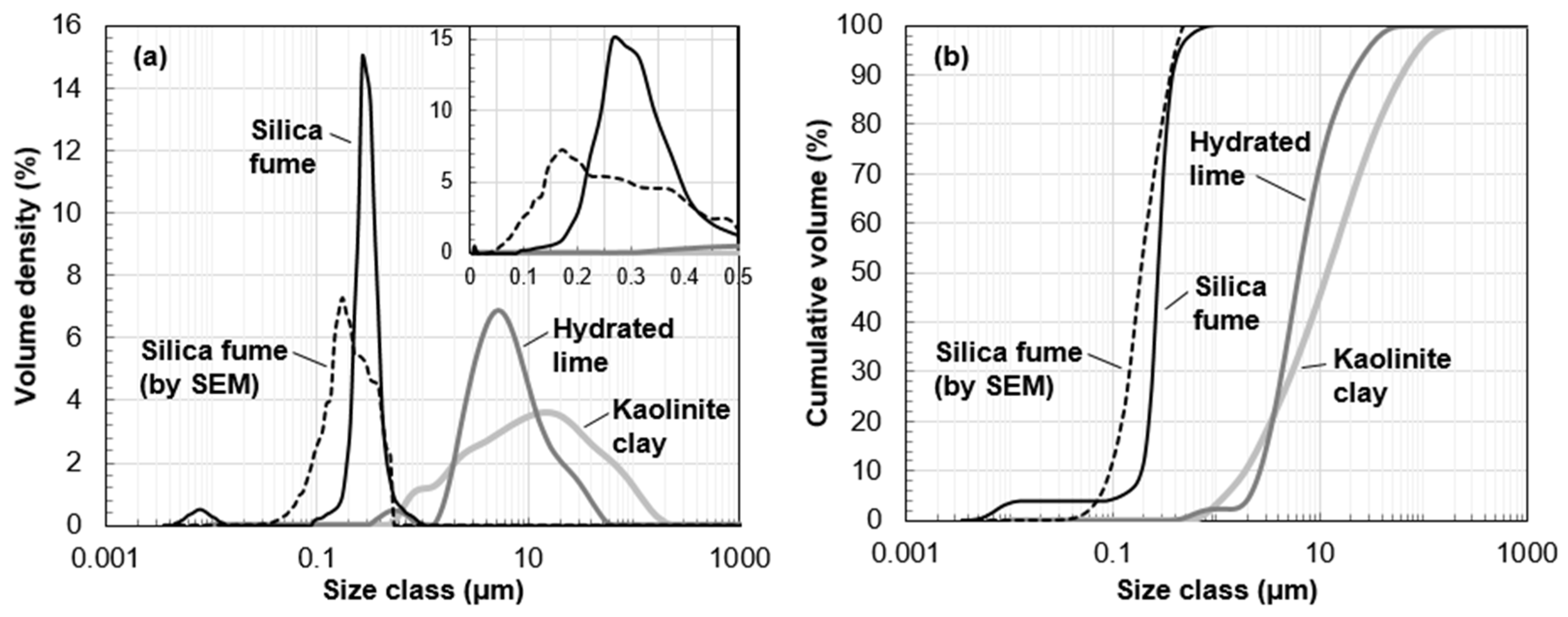
2.1. Materials
2.2. Mix Proportion
2.3. Specimen Preparation
2.4. Test Method
3. Results and Discussion
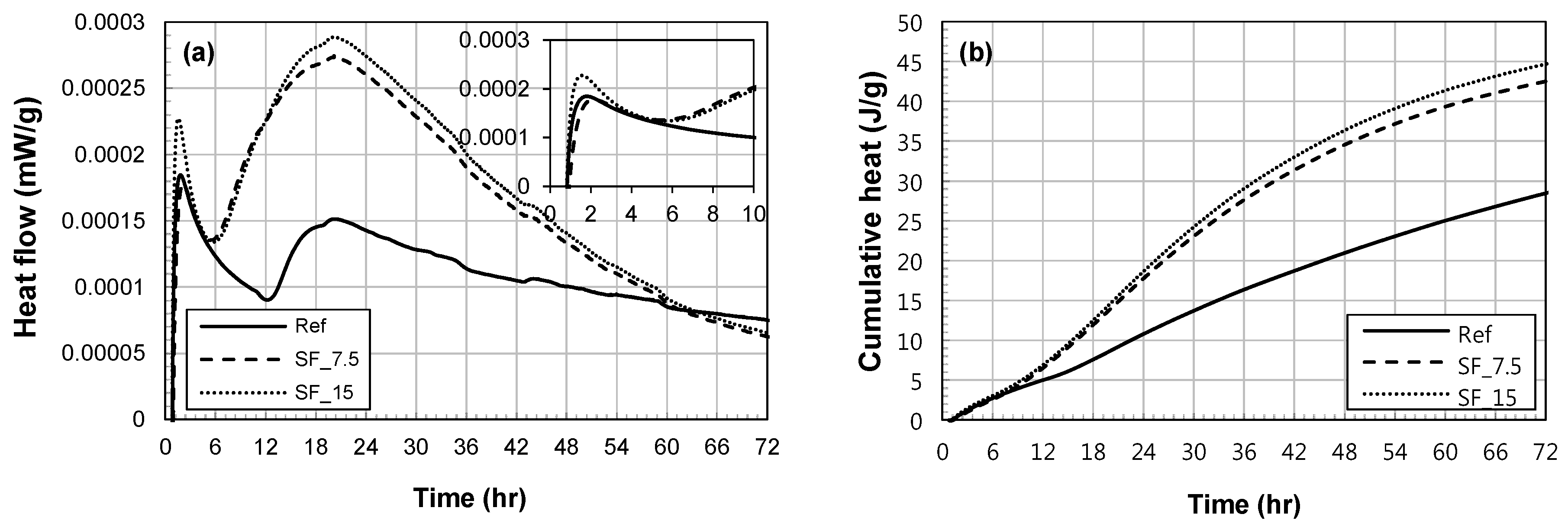
3.1. Heat of Hydration
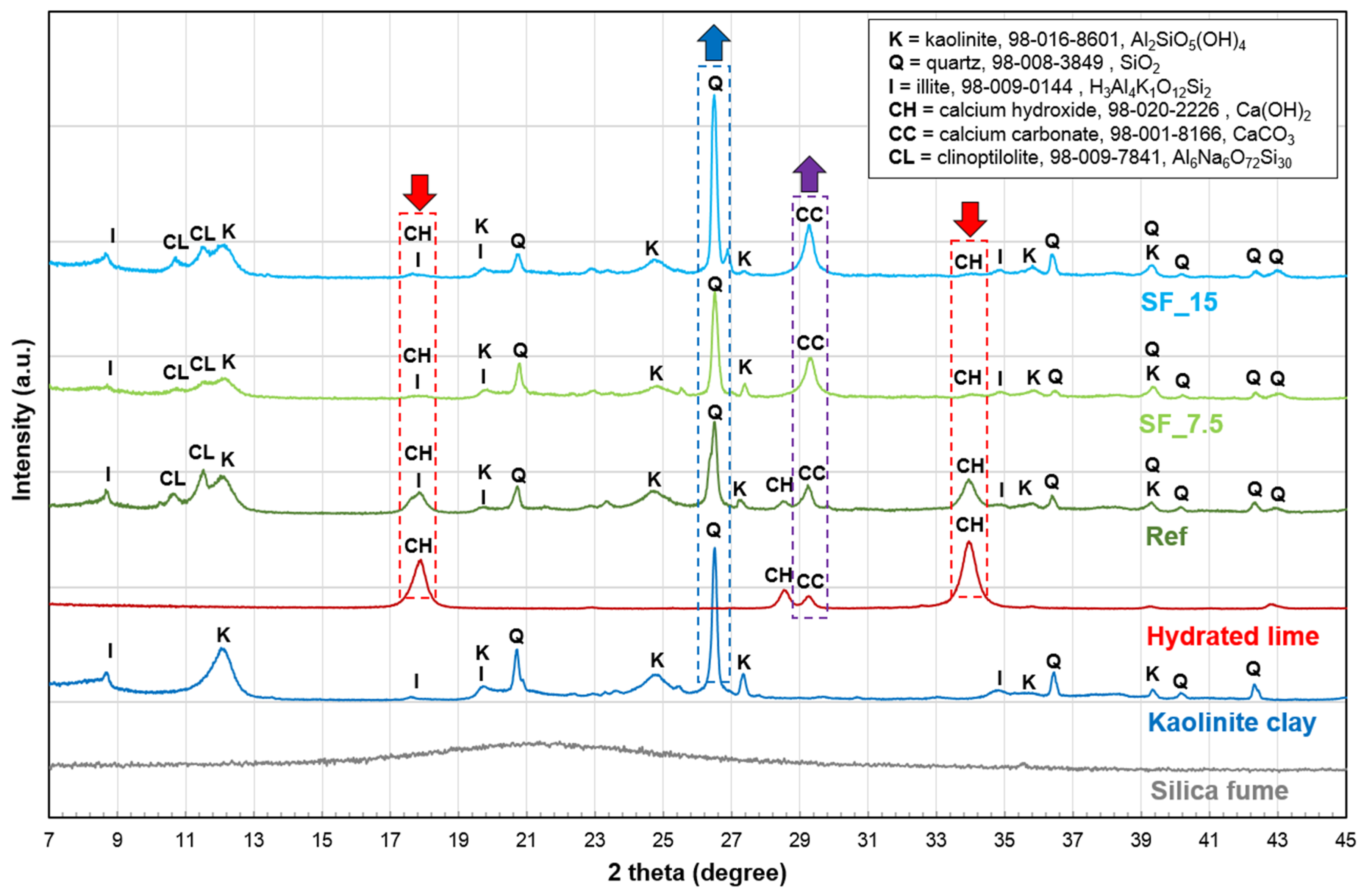
3.2. XRD Analysis
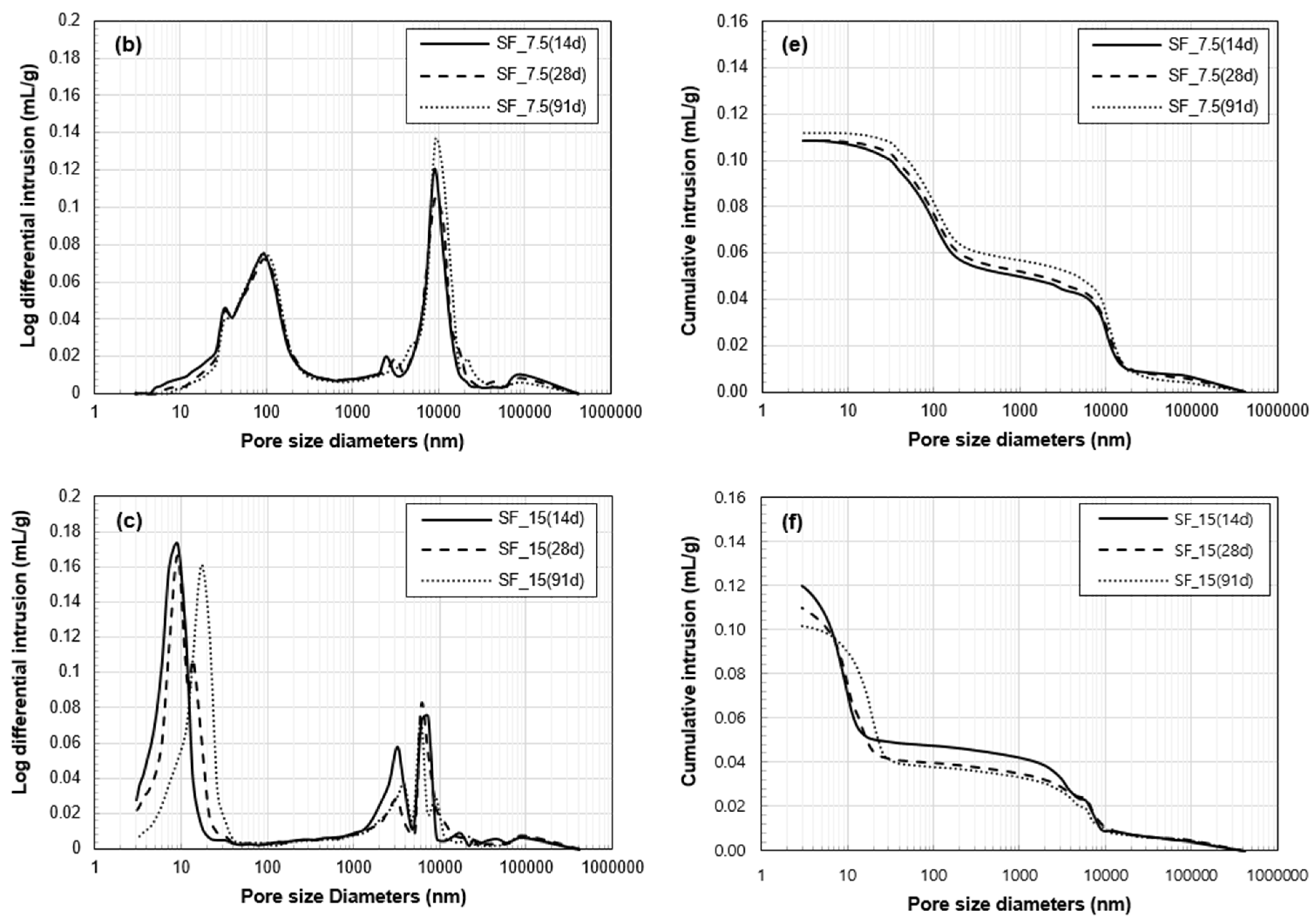
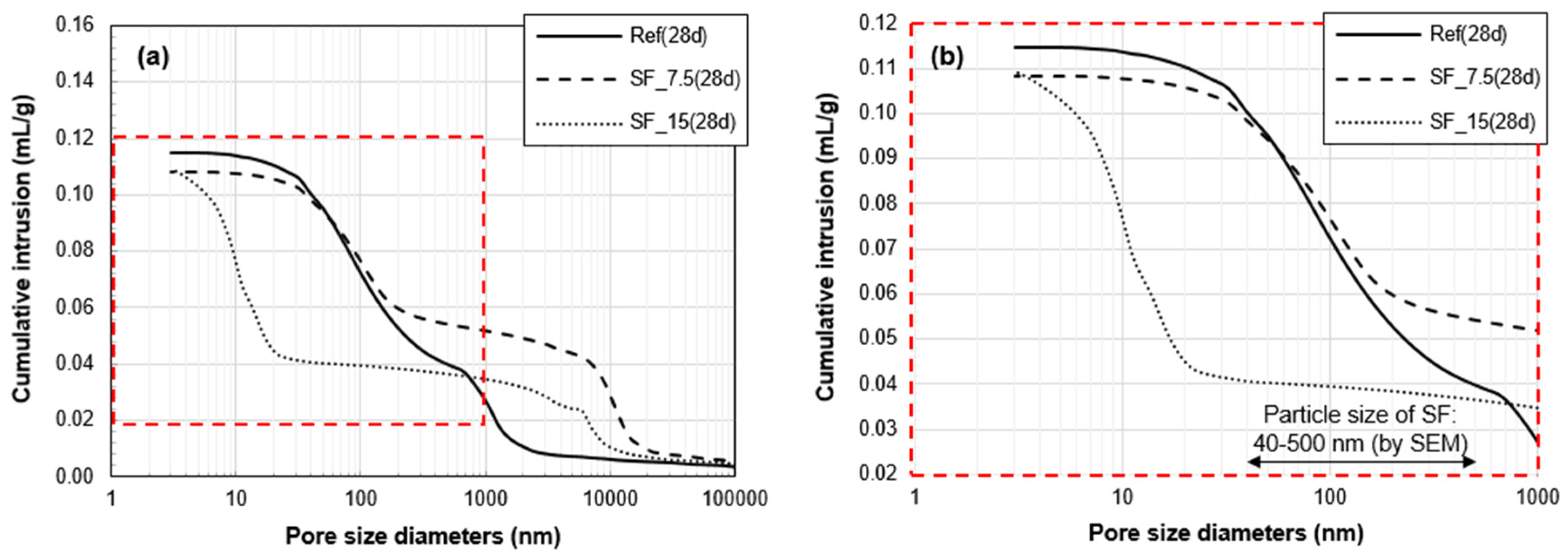
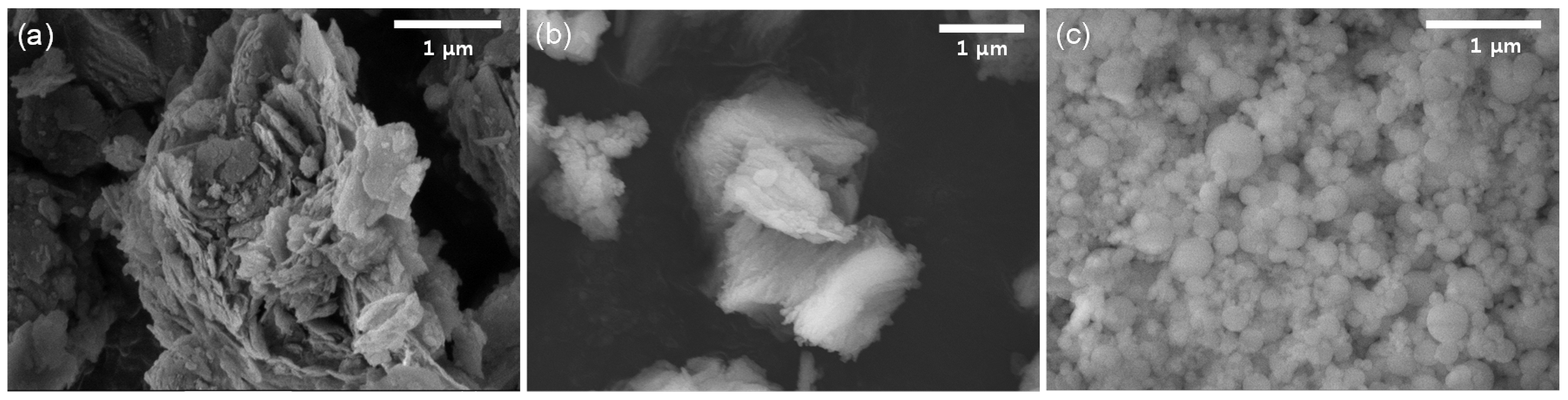
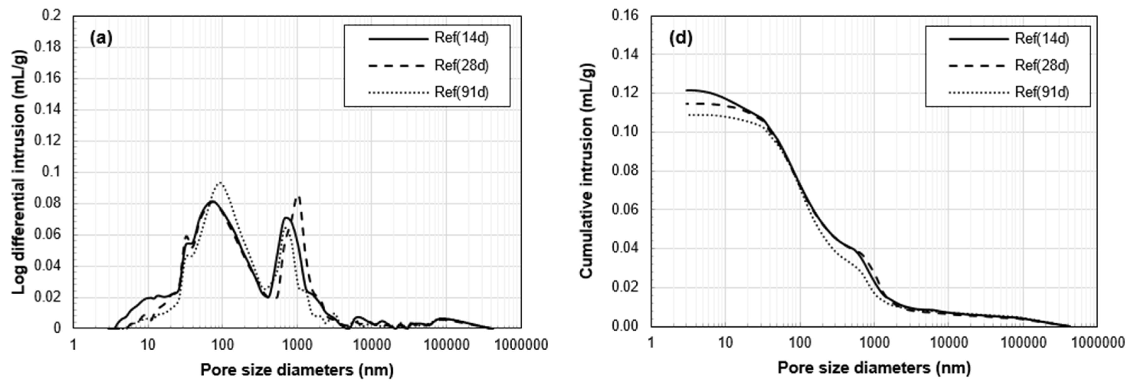
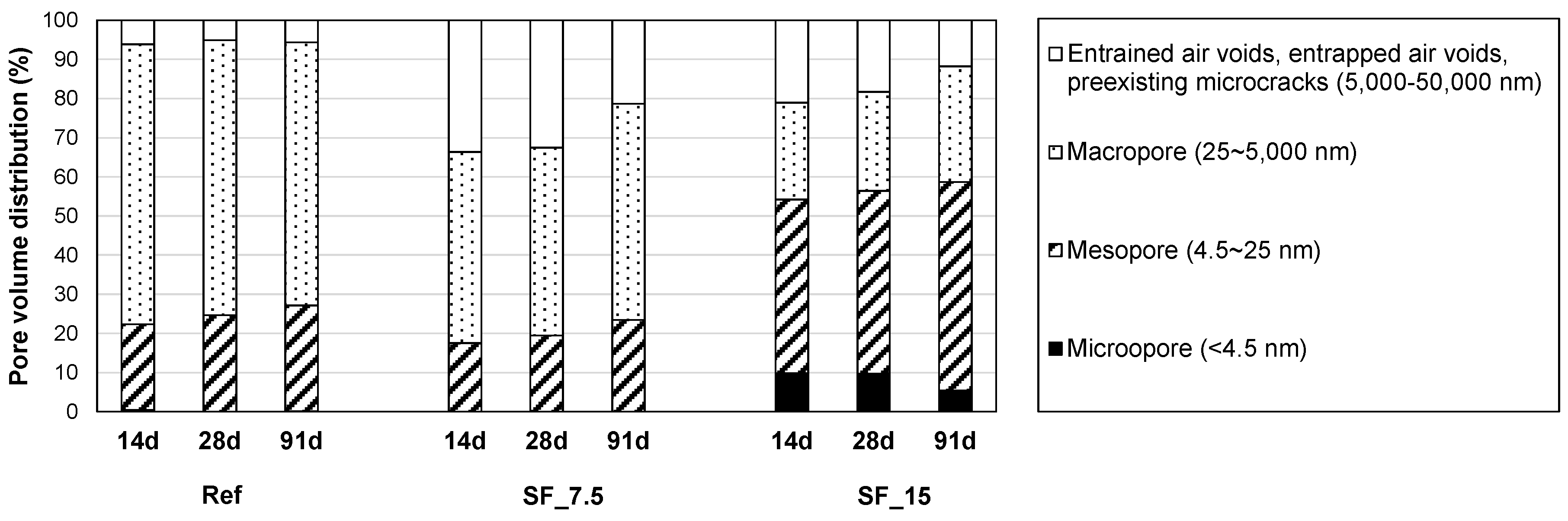
3.3. Porosity Analysis
3.4. Compressive Strength
3.5. Investigation on Strength Reduction
4. Conclusions
- (1)
- In the heat of hydration test, all samples showed two main peaks regardless of SF addition. SF addition increased the hydration heat emission. The interesting result is that the cumulative hydration heat of SF_15 was only 5% higher than that of SF_7.5, although SF content in SF_15 was almost twice than that in SF_7.5. This result reveals that the excessive addition of SF has no chemical effect on the hydration reaction.
- (2)
- The XRD analysis showed that the mortar cured for 28 days contains quartz, kaolinite, illite, remaining calcium hydroxide, calcium carbonate, and clinoptilolite. Unlike Ref, calcium hydroxide was barely detected in two SF samples (SF_7.5 and SF_15), i.e., it was mostly consumed by the intended pozzolanic reaction between hydrated lime and SF. Thus, the intensified hydration reaction that was confirmed by the hydration heat test, was attributed to the intended pozzolanic reaction by adding two mineral admixtures.
- (3)
- The total pore volume of the two samples with SF was lower than that of Ref. Between the two samples with SF, the proportion of the pores, whose size range is similar with that of SF particles, was significantly lower in SF_15 than SF_7.5. This verifies the physical filling effect provided by excessive (unreacted) SF particles. However, in the pore size distribution of SF_15, the first peak was changed from 9 to 17 nm between 28 and 91 days. This change can be related to the long-term strength reduction in a fine pore structure of SF_15.
- (4)
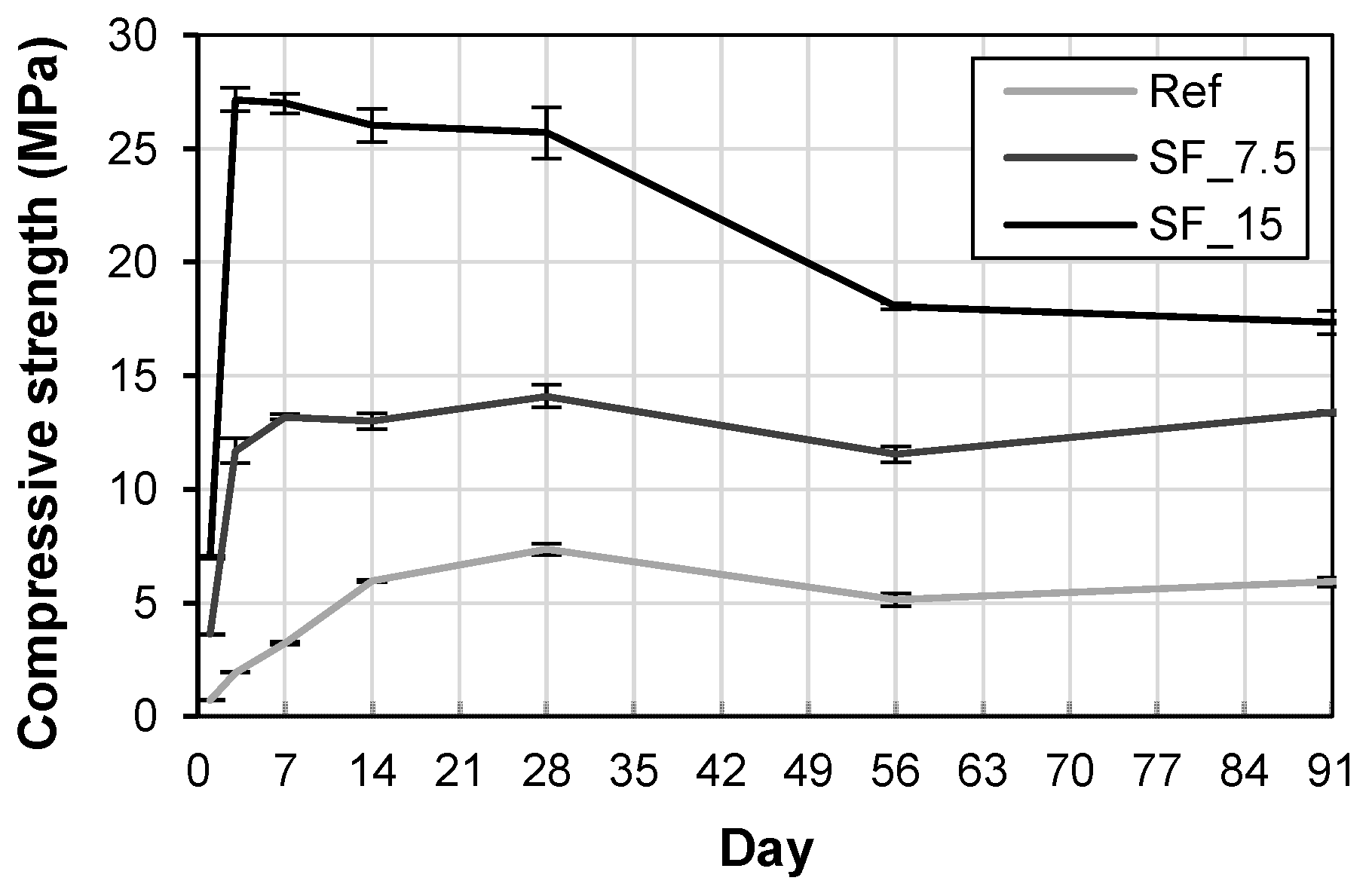
- The compressive strength of the mortar was increased with SF addition. The main contribution was the intended pozzolanic reaction, but the filling effect also contributed to the strength gain as well. Based on the compressive strength, it was confirmed that the developed kaolinite clay-based mortar with SF has sufficient mechanical properties as a structural material.
- (5)
- However, there is an optimal SF to binder ratio in the developed mortar. Excessive SF addition resulted in the degradation of long-term compressive strength. Considering price competitiveness and long-term strength, a SF to binder ratio of 7.5%, rather than 15%, is suitable. However, it should be noted that this optimum amount of SF can be different depending on the binder selection (i.e., the ratio of kaolinite clay and calcium hydroxide). The investigated mix design herein can be further expanded to develop other sustainable structural materials, such as natural minerals with low reactivity or waste materials with nonbinding properties.
Acknowledgments
Author Contributions
Conflicts of Interest
References
- Torgal, F.P.; Miraldo, S.; Labrincha, J.; De Brito, J. An overview on concrete carbonation in the context of eco-efficient construction: Evaluation, use of SCMs and/or RAC. Constr. Build. Mater. 2012, 36, 141–150. [Google Scholar] [CrossRef]
- Yang, K.H.; Hwang, H.Z.; Lee, S. Effects of water-binder ratio and fine aggregate–total aggregate ratio on the properties of Hwangtoh-based alkali-activated concrete. J. Mater. Civ. Eng. 2010, 22, 887–896. [Google Scholar] [CrossRef]
- Ahmed, A.M. Physical properties of geopolymer concrete incorporating silica fume and ground granulated blast-furnace slag. Int. J. Sci. Res. 2015, 4, 2415–2419. [Google Scholar]
- Yang, K.H.; Hwang, H.Z.; Kim, S.Y.; Song, J.K. Development of a cementless mortar using hwangtoh binder. Build. Environ. 2007, 42, 3717–3725. [Google Scholar] [CrossRef]
- Atiş, C.D. Heat evolution of high-volume fly ash concrete. Cem. Concr. Res. 2002, 32, 751–756. [Google Scholar] [CrossRef]
- Li, G. Properties of high-volume fly ash concrete incorporating nano-SiO2. Cem. Concr. Res. 2004, 34, 1043–1049. [Google Scholar] [CrossRef]
- Sobolev, K. Mechano-chemical modification of cement with high volumes of blast furnace slag. Cem. Concr. Compos. 2005, 27, 848–853. [Google Scholar] [CrossRef]
- Adam, A.; Molyneaux, T.; Patnaikuni, I.; Law, D. Strength, sorptivity and carbonation of geopolymer concrete. In Challenges, Opportunities and Solutions in Structural Engineering and Construction; CRC Press: Boca Raton, FL, USA, 2010; pp. 563–568. [Google Scholar]
- Monteiro, P.J.; Clodic, L.; Battocchio, F.; Kanitpanyacharoen, W.; Chae, S.R.; Ha, J.; Wenk, H.R. Incorporating carbon sequestration materials in civil infrastructure: A micro and mano-structural analysis. Cem. Concr. Compos. 2013, 40, 14–20. [Google Scholar] [CrossRef]
- Menéndez, G.; Bonavetti, V.; Irassar, E.F. Strength development of ternary blended cement with limestone filler and blast-furnace slag. Cem. Concr. Compos. 2003, 25, 61–67. [Google Scholar] [CrossRef]
- Poppe, A.M.; De Schutter, G. Cement hydration in the presence of high filler contents. Cem. Concr. Res. 2005, 35, 2290–2299. [Google Scholar] [CrossRef]
- Pelletier-Chaignat, L.; Winnefeld, F.; Lothenbach, B.; Müller, C.J. Beneficial use of limestone filler with calcium sulphoaluminate cement. Constr. Build. Mater. 2012, 26, 619–627. [Google Scholar] [CrossRef]
- Aqel, M.; Panesar, D.K. Hydration kinetics and compressive strength of steam-cured cement pastes and mortars containing limestone filler. Constr. Build. Mater. 2016, 113, 359–368. [Google Scholar] [CrossRef]
- Lothenbach, B.; Scrivener, K.; Hooton, R.D. Supplementary cementitious materials. Cem. Concr. Res. 2001, 41, 1244–1256. [Google Scholar] [CrossRef]
- Kwon, Y.H.; Kang, S.H.; Hong, S.G.; Moon, J. Acceleration of intended pozzolanic reaction under initial thermal treatment for developing cementless fly ash based mortar. Materials 2017, 10, 225. [Google Scholar] [CrossRef]
- Jeong, Y.; Park, H.; Jun, Y.; Jeong, J.H.; Oh, J.E. Influence of slag characteristics on strength development and reaction products in a CaO-activated slag system. Cem. Concr. Compos. 2016, 72, 155–167. [Google Scholar] [CrossRef]
- Neto, A.A.M.; Cincotto, M.A.; Repette, W. Drying and autogenous shrinkage of pastes and mortars with activated slag cement. Cem. Concr. Res. 2008, 38, 565–574. [Google Scholar] [CrossRef]
- Zhang, W.; Hama, Y.; Na, S.H. Drying shrinkage and microstructure characteristics of mortar incorporating ground granulated blast furnace slag and shrinkage reducing admixture. Constr. Build. Mater. 2015, 93, 267–277. [Google Scholar] [CrossRef]
- Bilim, C.; Karahan, O.; Atiş, C.D.; İlkentapar, S. Influence of admixtures on the properties of alkali-activated slag mortars subjected to different curing conditions. Mater. Des. 2013, 44, 540–547. [Google Scholar] [CrossRef]
- Nežerka, V.; Slížková, Z.; Tesárek, P.; Plachý, T.; Frankeová, D.; Petráňová, V. Comprehensive study on mechanical properties of lime-based pastes with additions of metakaolin and brick dust. Cem. Concr. Res. 2014, 64, 17–29. [Google Scholar] [CrossRef]
- Papadakis, V.G.; Tsimas, S. Supplementary cementing materials in concrete: Part I: Efficiency and design. Cem. Concr. Res. 2002, 32, 1525–1532. [Google Scholar] [CrossRef]
- Siddique, R.; Klaus, J. Influence of metakaolin on the properties of mortar and concrete: A review. Appl. Clay Sci. 2009, 43, 392–400. [Google Scholar] [CrossRef]
- Kim, B.J.; Yi, C.; Kang, K.I. Development of alkali-activated binder using hwangtoh without calcination. Constr. Build. Mater. 2014, 58, 206–213. [Google Scholar] [CrossRef]
- Malhotra, V.M. Introduction: Sustainable development and concrete technology. Concr. Int. 2002, 24, 7. [Google Scholar]
- Go, S.S.; Lee, H.C.; Lee, J.Y.; Kim, J.H.; Chung, C.W. Experimental investigation of mortars using activated Hwangtoh. Constr. Build. Mater. 2009, 23, 1438–1445. [Google Scholar] [CrossRef]
- Go, S.S.; Chung, C.W.; Struble, L.J.; Lee, H.C. Pozzolanic activity of Hwangtoh clay. Constr. Build. Mater. 2010, 24, 2638–2645. [Google Scholar] [CrossRef]
- Hwang, H.Z.; Kang, N.Y. Preliminary study on traditional earth construction technique use of lime. J. Korea Inst. Ecol. Archit. Environ. 2010, 10, 3–8. [Google Scholar]
- Administration, C.H. Cultural Heritage Repair Standard Specification; Design DNA: Daejeon, Korea, 2014; p. 380. [Google Scholar]
- Ahn, J.C. A Fundamental Study in the Properties of the Loess Mortar Mixed with Lime (Samwhato). Master’s Thesis, Dong-A University, Pusan, Korea, 1997. [Google Scholar]
- Hwang, H.Z. A Study on the Method of Activating Kaoline and the Mortar & Concrete Mixed with Active-Kaoline. Ph.D. Thesis, Seoul National University, Seoul, Korea, 1997. [Google Scholar]
- Wang, S.D.; Pu, X.C.; Scrivener, K.L.; Pratt, P.L. Alkali-activated slag cement and concrete: A review of properties and problems. Adv. Cem. Res. 1995, 7, 93–102. [Google Scholar] [CrossRef]
- Kim, M.S.; Jun, Y.; Lee, C.; Oh, J.E. Use of CaO as an activator for producing a price-competitive non-cement structural binder using ground granulated blast furnace slag. Cem. Concr. Res. 2013, 54, 208–214. [Google Scholar] [CrossRef]
- Khater, H.M. Effect of silica fume on the characterization of the geopolymer materials. Int. J. Adv. Struct. Eng. 2013, 5, 1–10. [Google Scholar] [CrossRef]
- Malhotra, V.M.; Mehta, P.K. Pozzolanic and Cementitious Materials; Gordon and Breach Publishers: Amsterdam, The Netherlands, 1996; Volume 1. [Google Scholar]
- Diamond, S.; Sahu, S. Densified silica fume: Particle sizes and dispersion in concrete. Mater. Struct. 2006, 39, 849–859. [Google Scholar] [CrossRef]
- Cement-Test Methods-Determination of Strength; ISO 679:2009; International Organization for Standardization: Geneva, Switzerland, 2009; p. 29.
- Standard Practice for Mechanical Mixing of Hydraulic Cement Pastes and Mortars of Plastic Consistency; ASTM C305; Annual Book of ASTM; American Society for Testing and Materials (ASTM): West Conshohocken, PA, USA, 2014; p. 3.
- Belsky, A.; Hellenbrandt, M.; Karen, V.L.; Luksch, P. New developments in the Inorganic Crystal Structure Database (ICSD): Accessibility in support of materials research and design. Acta Crystallogr. Sect. B 2002, 58, 364–369. [Google Scholar] [CrossRef]
- Standard Test Method for Compressive Strength of Hydraulic Cement Mortars (Using 2-in or [50-Mm] Cube Specimens); ASTM C109/C109M; Annual Book of ASTM; American Society for Testing and Materials (ASTM): West Conshohocken, PA, USA, 2013; p. 10.
- Gameiro, A.; Silva, A.S.; Faria, P.; Grilo, J.; Branco, T.; Veiga, R.; Velosa, A. Physical and chemical assessment of lime–metakaolin mortars: Influence of binder: Aggregate ratio. Cem. Concr. Compos. 2014, 45, 264–271. [Google Scholar] [CrossRef]
- Fernández, J.M.; Duran, A.; Navarro-Blasco, I.; Lanas, J.; Sirera, R.; Alvarez, J.I. Influence of nanosilica and a polycarboxylate ether superplasticizer on the performance of lime mortars. Cem. Concr. Res. 2013, 43, 12–24. [Google Scholar] [CrossRef]
- Bhattacharyya, K.G.; Gupta, S.S. Adsorption of a few heavy metals on natural and modified kaolinite and montmorillonite: A review. Adv. Colloid Interface Sci. 2008, 140, 114–131. [Google Scholar] [CrossRef] [PubMed]
- Khan, M.I.; Lynsdale, C.J. Strength, permeability, and carbonation of high-performance concrete. Cem. Concr. Res. 2002, 32, 121–131. [Google Scholar] [CrossRef]
- Skjolsvold, O. Carbonation depths of concrete with and without condensed silica fume. Spec. Publ. 1986, 91, 1031–1048. [Google Scholar]
- Collins, F.; Sanjayan, J.G. Effect of pore size distribution on drying shrinking of alkali-activated slag concrete. Cem. Concr. Res. 2002, 30, 1401–1406. [Google Scholar] [CrossRef]
- Wu, Z.; Shi, C.; Khayat, K.H. Influence of silica fume content on microstructure development and bond to steel fiber in ultra-high strength cement-based materials (UHSC). Cem. Concr. Compos. 2016, 71, 97–109. [Google Scholar] [CrossRef]
- Mehta, P.; Monteiro, P.J. Concrete, Microstructure, Properties and Materials; McGraw-Hill Publishing: London, UK, 2006. [Google Scholar]
- Lura, P.; Jensen, O.M.; van Breugel, K. Autogenous shrinkage in high-performance cement paste: An evaluation of basic mechanisms. Cem. Concr. Res. 2003, 33, 223–232. [Google Scholar] [CrossRef]
- Lura, P.; Durand, F.; Loukili, A.; Kovler, K.; Jensen, O.M. Compressive strength of cement pastes and mortars with superabsorbent polymers. In Proceedings of the International RILEM Conference on Volume Changes of Hardening Concrete: Testing and Mitigation, Lyngby, Denmark, 20–23 August 2006. [Google Scholar]
- Rao, G.A. Long-term drying shrinkage of mortar—Influence of silica fume and size of fine aggregate. Cem. Concr. Res. 2001, 31, 171–175. [Google Scholar] [CrossRef]


| Chemical Composition | SiO2 | Al2O3 | TiO2 | Fe2O3 | MgO | CaO | Na2O | K2O | MnO | P2O5 | LOI 1 | Total |
|---|---|---|---|---|---|---|---|---|---|---|---|---|
| Kaolinite clay | 55.34 | 22.33 | 1.04 | 8.43 | 0.52 | 1.46 | 0.10 | 2.49 | 0.07 | 0.10 | 8.02 | 99.91 |
| Hydrated lime | 0.57 | 0.54 | 0.01 | 0.14 | 1.12 | 74.51 | 0.01 | 0.12 | 0.004 | 0.01 | 23.00 | 100.03 |
| Silica fume | 96.90 | 0.29 | 0.01 | 0.15 | 0.18 | 1.54 | 0.16 | 0.64 | 0.03 | 0.05 | 0.02 | 99.97 |
| Sample Name | Water/Binder | Total Binder (%) | SF/Binder | Superplasticizer/Binder | Fine Aggregate/Binder |
|---|---|---|---|---|---|
| Kaolinite Clay/Hydrated Lime | |||||
| Ref | 0.4 | 70:30 | 0 | 0.06 | 3 |
| SF_7.5 | 0.075 | ||||
| SF_15 | 0.15 |
© 2017 by the authors. Licensee MDPI, Basel, Switzerland. This article is an open access article distributed under the terms and conditions of the Creative Commons Attribution (CC BY) license (http://creativecommons.org/licenses/by/4.0/).
Share and Cite
Kwon, Y.-H.; Kang, S.-H.; Hong, S.-G.; Moon, J. Intensified Pozzolanic Reaction on Kaolinite Clay-Based Mortar. Appl. Sci. 2017, 7, 522. https://doi.org/10.3390/app7050522
Kwon Y-H, Kang S-H, Hong S-G, Moon J. Intensified Pozzolanic Reaction on Kaolinite Clay-Based Mortar. Applied Sciences. 2017; 7(5):522. https://doi.org/10.3390/app7050522
Chicago/Turabian StyleKwon, Yang-Hee, Sung-Hoon Kang, Sung-Gul Hong, and Juhyuk Moon. 2017. "Intensified Pozzolanic Reaction on Kaolinite Clay-Based Mortar" Applied Sciences 7, no. 5: 522. https://doi.org/10.3390/app7050522
APA StyleKwon, Y.-H., Kang, S.-H., Hong, S.-G., & Moon, J. (2017). Intensified Pozzolanic Reaction on Kaolinite Clay-Based Mortar. Applied Sciences, 7(5), 522. https://doi.org/10.3390/app7050522